CN212711640U - Automatic feeding machine for printing plate - Google Patents
Automatic feeding machine for printing plate Download PDFInfo
- Publication number
- CN212711640U CN212711640U CN202021360262.6U CN202021360262U CN212711640U CN 212711640 U CN212711640 U CN 212711640U CN 202021360262 U CN202021360262 U CN 202021360262U CN 212711640 U CN212711640 U CN 212711640U
- Authority
- CN
- China
- Prior art keywords
- moving
- plate
- rotating shaft
- frame
- guide
- Prior art date
- Legal status (The legal status is an assumption and is not a legal conclusion. Google has not performed a legal analysis and makes no representation as to the accuracy of the status listed.)
- Active
Links
Images



Landscapes
- Sheets, Magazines, And Separation Thereof (AREA)
Abstract
The application relates to an automatic feeding machine for a printing plate, which relates to the field of exposure machines and comprises a horizontally arranged discharging platform and a guide frame which is obliquely arranged towards one side of a feeding hole, wherein one end of the guide frame is fixedly connected to one side, close to the feeding hole of the exposure machine, of the discharging platform; the guide frame is provided with a suction device, the suction device comprises a moving frame, the moving frame is rotatably connected with a fixed plate, the bottom of the fixed plate is connected with a moving plate in a sliding manner, the moving plate is provided with a plurality of negative pressure tubes perpendicular to the moving plate, the bottom of each negative pressure tube is communicated with a sucker, one end of each negative pressure tube, which is far away from the sucker, is communicated with a vacuum generator, and one end of the vacuum generator, which is far away from the negative pressure tubes, is communicated with an air source; the guide frame is provided with a moving device for driving the moving frame to slide along the length direction of the guide frame, the moving frame is provided with a turnover device for turning over the fixed plate, and the fixed plate is provided with a lifting device for driving the moving plate to lift. This application has the effect of using manpower sparingly.
Description
Technical Field
The application relates to the field of exposure machines, in particular to an automatic printing plate feeding machine.
Background
At present, a printing plate is a printing screen plate, and in the manufacturing step of the printing screen plate, a photosensitive resist is coated on the screen plate, then an exposure negative film is covered on the screen plate coated with the photosensitive resist, and finally the screen plate enters an exposure machine through a feed inlet which is obliquely arranged on the exposure machine, and a printing grid path is formed on the screen plate after the screen plate is exposed.
In the prior art, reference may be made to a chinese utility model patent with an authorized publication number of CN208547808U, which discloses a separated exposure device for a tension-adjustable printing screen, comprising a track, a mobile station, an exposure table, an exposure film, a fine adjustment mechanism, a support plate and a tensioning mechanism; the tensioning mechanism comprises a tensioning screw rod, a tensioning nut and a tensioning sleeve; two sides of the upper end of the exposure platform are respectively and vertically provided with a tensioning screw, a tensioning nut is arranged on the tensioning screw in a threaded manner, and the lower end of a tensioning sleeve is sleeved at the upper end of the tensioning screw in a sliding manner; the tensioning nut is positioned below the tensioning sleeve; the tensioning nut drives the tensioning sleeve to move upwards; the tensioning sleeve upwards supports and presses two sides of the exposure negative film.
With respect to the related art among the above, the inventors consider that the following drawbacks exist: before the exposure negative film is exposed, the exposure machine needs to manually place the printing plate into the exposure machine, which wastes manpower.
SUMMERY OF THE UTILITY MODEL
In order to use manpower sparingly, this application provides a printing plate automatic feeding machine.
The application provides a seal board automatic feeding machine adopts following technical scheme:
an automatic feeding machine for printing plates comprises a horizontally arranged discharging platform and a guide frame which is obliquely arranged towards one side of a feeding hole, wherein one end of the guide frame is fixedly connected to one side, close to the feeding hole of an exposure machine, of the discharging platform; the guide frame is provided with a suction device, the suction device comprises a moving frame, the moving frame is rotatably connected with a fixed plate, the bottom of the fixed plate is connected with a moving plate in a sliding manner, the moving plate is provided with a plurality of negative pressure tubes perpendicular to the moving plate, the bottom of each negative pressure tube is communicated with a sucker, one end, far away from the sucker, of each negative pressure tube is communicated with a vacuum generator, and one end, far away from the negative pressure tube, of the vacuum generator is communicated with an air source; be provided with on the leading truck and be used for the drive to remove the mobile device that the frame slided along leading truck length direction, remove and install the turning device who is used for the upset fixed plate on the frame, be provided with the elevating gear who is used for driving the movable plate lift on the fixed plate.
By adopting the technical scheme, when the printing plates are stacked on the discharging table, the moving frame is moved to the position above the printing plates through the moving device, the fixed plate is rotated through the turnover device, when the air suction port of the sucking disc is positioned right above the printing plates, the moving plate is lowered through the lifting device, at the moment, the vacuum generator is started, the sucking disc generates suction under the action of the air source and the negative pressure pipe, and the printing plates are adsorbed on the sucking disc; then, the moving plate is lifted through the lifting device, then the moving frame is driven by the moving device to move from the bottom to the top of the guide frame, and meanwhile, the sucker is perpendicular to the inclined surface of the feed port of the exposure machine through the overturning device; when the moving plate rises to the top of the guide frame, the vacuum generator is closed at the moment, the printing plate is separated from the action of the sucker and finally falls into the feed inlet of the exposure machine, and the steps are repeated, so that the automatic feeding function is realized, and the labor is saved.
Preferably, the lifting device comprises a first rotating shaft, a driving assembly and two groups of lifting assemblies; the first rotating shaft is rotatably connected to the top of the fixing plate, the axis of the first rotating shaft is arranged along the length direction of the fixing plate, and the driving assembly is used for driving the first rotating shaft to rotate; each group of lifting assemblies comprises a rack and a first gear, each first gear is sleeved and fixed on the first rotating shaft, one end of each rack is fixed at the top of the movable plate, a sliding groove used for enabling one end, far away from the movable plate, of each rack to move in the direction perpendicular to the axial direction of the first rotating shaft is formed in the fixed plate, and the first gears are meshed with the racks at the same side.
Through adopting above-mentioned technical scheme, rotate through the first axis of rotation of drive assembly drive, first axis of rotation rotates and drives two first gear rotations, and two first gear rotations drive two racks lift, and two racks lift drive movable plate lifts.
Preferably, the driving assembly comprises a brake motor, a second gear and a third gear; the brake motor is horizontally arranged at the top of the fixing plate, the second gear is sleeved and fixed on an output shaft of the brake motor, the third gear is sleeved and fixed on the first rotating shaft, and the second gear is meshed with the third gear.
Through adopting above-mentioned technical scheme, start brake motor, brake motor's output shaft rotates and drives the second gear rotation, and the rotation of second gear drives the rotation of third gear, and the rotation of third gear drives first axis of rotation and rotates.
Preferably, a plurality of first guide rods are fixedly connected to the top of the moving plate vertically, one end, far away from the moving plate, of each first guide rod penetrates through the fixed plate and is fixedly connected with a stop block, and each first guide rod is connected to the fixed plate in a sliding mode along the length direction parallel to the rack.
Through adopting above-mentioned technical scheme, first guide arm has the effect of direction to the movable plate to can reduce the movable plate and take place the skew possibility in the in-process of going up and down.
Preferably, the turnover device comprises two second rotating shafts, one end of each second rotating shaft is rotatably connected to one end of the movable frame, and the other end of each second rotating shaft is fixedly connected to one end of the fixed plate; the turnover device also comprises a first belt transmission mechanism for driving the second rotating shaft to rotate.
Through adopting above-mentioned technical scheme, drive the second axis of rotation through first area drive mechanism and rotate, the second axis of rotation rotates the drive fixed plate and rotates.
Preferably, the moving device comprises a third rotating shaft arranged along the width direction of the guide frame, the third rotating shaft is rotatably connected to the top of the guide frame, and both ends of the third rotating shaft are respectively sleeved and fixed with a first belt wheel; two ends of the bottom of the guide frame are respectively and rotatably connected with a second belt wheel, a first belt is arranged on the first belt wheel and the second belt wheel which are positioned on the same side, and the first belt is used for enabling the first belt wheel and the second belt wheel which are positioned on the same side to be linked; two ends of the movable frame are respectively fixedly connected with the two first belts, and a second belt transmission mechanism for driving a third rotating shaft to rotate is arranged at the top of the fixed frame; the moving device further comprises a guide assembly for guiding the moving frame.
Through adopting above-mentioned technical scheme, make the third axis of rotation take place to rotate through second drive mechanism, the third axis of rotation rotates and drives two first pulleys and rotate simultaneously, and two first pulleys rotate simultaneously and drive first belt and rotate, combine the guide effect of direction subassembly, and first belt rotates and drives and remove the frame and remove.
Preferably, the guide assembly comprises two second guide rods, wherein two ends of each second guide rod are fixedly connected to the top and the bottom of the guide frame respectively, each second guide rod penetrates through one end of the movable frame, and the movable frame is connected to the second guide rods in a sliding mode along the length direction of the mounting frame.
Through adopting above-mentioned technical scheme, the second guide arm has the effect of direction to moving the frame to can reduce the moving frame and take place the possibility of skew at the in-process that moves along the length direction of mounting bracket.
Preferably, the second belt transmission mechanism includes a driving motor horizontally mounted on one side of the top of the guiding frame, a third belt wheel sleeved and fixedly connected to an output shaft of the driving motor, a fourth belt wheel sleeved and fixedly connected to the third rotating shaft, and a second belt for linking the third belt wheel and the fourth belt wheel.
By adopting the technical scheme, the driving motor is started, the output shaft of the driving motor rotates to drive the third belt wheel to rotate, the third belt wheel rotates to drive the second belt wheel to rotate, the second belt wheel rotates to drive the fourth belt wheel to rotate, and the fourth belt wheel rotates to drive the third rotating shaft to rotate.
In summary, the present application includes at least one of the following beneficial technical effects:
1. when the printing plates are stacked on the material placing table, the moving frame is moved to the position above the printing plates through the moving device, meanwhile, the fixed plate is rotated through the overturning device, when the air suction port of the sucking disc is positioned right above the printing plates, the moving plate is lowered through the lifting device, at the moment, the vacuum generator is started, under the action of the air source and the negative pressure pipe, the sucking disc generates suction, and the printing plates are adsorbed on the sucking disc; then, the moving plate is lifted through the lifting device, then the moving frame is driven by the moving device to move from the bottom to the top of the guide frame, and meanwhile, the sucker is perpendicular to the inclined surface of the feed port of the exposure machine through the overturning device; when the moving plate rises to the top of the guide frame, the vacuum generator is closed at the moment, the printing plate is separated from the action of the sucker and finally falls into the feed port of the exposure machine, and the steps are repeated, so that the automatic feeding function is realized, and the labor is saved;
2. the driving assembly drives the first rotating shaft to rotate, the first rotating shaft rotates to drive the two first gears to rotate, the two first gears rotate to drive the two racks to lift, and the two racks lift to drive the moving plate to lift;
3. the first guide rod has a guiding function on the moving plate, so that the possibility of deviation of the moving plate in the lifting process can be reduced.
Drawings
Fig. 1 is a schematic overall structure diagram of the application embodiment.
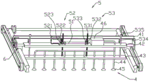
Fig. 2 is a schematic structural diagram of a suction device and a lifting device according to an embodiment of the present application.
Fig. 3 is a schematic structural diagram of the turning device according to the embodiment of the application.
Fig. 4 is a schematic structural diagram of a mobile device according to an embodiment of the present application.
Description of reference numerals: 1. a discharge table; 2. a guide frame; 3. a feed port of the exposure machine; 4. a suction device; 41. a movable frame; 42. a fixing plate; 43. moving the plate; 44. a negative pressure tube; 45. a suction cup; 46. a vacuum generator; 5. a lifting device; 51. a first rotating shaft; 52. a drive assembly; 521. braking the motor; 522. a second gear; 523. a third gear; 53. a lifting assembly; 531. a rack; 532. a first gear; 533. a chute; 534. a first guide bar; 535. a stopper; 6. a turning device; 61. a second rotating shaft; 62. a first belt drive mechanism; 7. a mobile device; 71. a third rotating shaft; 72. a first pulley; 73. a second pulley; 74. a first belt; 75. a second belt drive mechanism; 751. a drive motor; 752. a third belt pulley; 753. a fourth pulley; 754. a second belt; 76. a guide assembly; 761. a second guide bar; 8. and (7) printing a plate.
Detailed Description
The present application is described in further detail below with reference to figures 1-4.
The embodiment of the application discloses seal board automatic feeding machine. Referring to fig. 1, the automatic plate feeder includes a horizontally disposed discharge table 1 and a guide frame 2 obliquely disposed toward a side of a feed port 3 of the exposure machine, and a suction device 4 is installed on the guide frame 2 in order to suck the printing plates 8 stacked on the discharge table 1.
Referring to fig. 2, the suction device 4 includes a moving frame 41, a fixed plate 42 is rotatably connected to the moving frame 41 through a bearing, a moving plate 43 is slidably connected to the bottom of the fixed plate 42, a plurality of negative pressure tubes 44 perpendicular to the moving plate 43 are mounted on the moving plate 43, a suction cup 45 is communicated with the bottom of each negative pressure tube 44, a vacuum generator 46 is communicated with one end of each negative pressure tube 44 far from the suction cup 45, and an air source is communicated with one end of the vacuum generator 46 far from the negative pressure tube 44; referring to fig. 1, a moving device 7 for driving the moving frame 41 to slide along the length direction of the guide frame 2 is provided on the guide frame 2, an overturning device 6 for overturning the fixed plate 42 is mounted on the moving frame 41, and a lifting device 5 for driving the moving plate 43 to lift is provided on the fixed plate 42.
When the printing plate 8 is stacked on the material placing table 1, the moving frame 41 is moved to the upper side of the printing plate 8 through the moving device 7, meanwhile, the fixed plate 42 is rotated through the overturning device 6, when the suction port of the suction cup 45 is positioned right above the printing plate 8, the moving plate 43 is lowered through the lifting device 5, at the moment, the vacuum generator 46 is started, under the action of the air source and the negative pressure pipe 44, the suction cup 45 generates suction, and the printing plate 8 is adsorbed on the suction cup 45; then the moving plate 43 is lifted by the lifting device 5, then the moving frame 41 is driven by the moving device 7 to move from the bottom to the top of the guide frame 2, and meanwhile the suction cup 45 is perpendicular to the inclined surface of the feed inlet 3 of the exposure machine by the overturning device 6; when the moving plate 43 rises to the top of the guide frame 2, the vacuum generator 46 is turned off, the printing plate 8 is separated from the action of the suction cup 45 and finally falls into the feed port 3 of the exposure machine, and the steps are repeated, so that the function of automatic feeding is realized, and the labor is saved.
Referring to fig. 2, the lifting device 5 includes a first rotating shaft 51, a driving assembly 52, and two sets of lifting assemblies 53; the first rotating shaft 51 is rotatably connected to the top of the fixed plate 42 through a bearing, and the axis of the first rotating shaft 51 is arranged along the length direction of the fixed plate 42; the driving assembly 52 includes a brake motor 521, a second gear 522 and a third gear 523; the brake motor 521 is horizontally arranged at the top of the fixed plate 42, the second gear 522 is fixedly sleeved on the output shaft of the brake motor 521, the third gear 523 is fixedly sleeved on the side wall of the first rotating shaft 51, and the second gear 522 is meshed with the third gear 523; each group of lifting assemblies 53 comprises a rack 531 and a first gear 532, each first gear 532 is sleeved and fixed on the side wall of the first rotating shaft 51, one end of each rack 531 is fixed on the top of the moving plate 43, a chute 533 used for enabling one end of the rack 531, which is far away from the moving plate 43, to move along the direction vertical to the axial direction of the first rotating shaft 51 is arranged on the fixed plate 42, and the first gear 532 on the same side is meshed with the rack 531; a plurality of first guide rods 534 are vertically and fixedly connected to the top of the moving plate 43, one end of each first guide rod 534, which is far away from the moving plate 43, penetrates through the fixed plate 42 and is fixedly connected with a stopper 535, and each first guide rod 534 is slidably connected to the fixed plate 42 along the length direction of the rack 531.
The brake motor 521 is started, the output shaft of the brake motor 521 rotates to drive the second gear 522 to rotate, the second gear 522 rotates to drive the third gear 523 to rotate, the third gear 523 rotates to drive the first rotating shaft 51 to rotate, the first rotating shaft 51 rotates to drive the two first gears 532 to rotate, the two first gears 532 rotate to drive the two racks 531 to lift, and the two racks 531 lift to drive the moving plate 43 to lift.
Referring to fig. 3, the turnover device 6 includes two second rotating shafts 61, one end of each second rotating shaft 61 is rotatably connected to one end of the moving frame 41 through a bearing, and the other end of each second rotating shaft 61 is fixedly connected to one end of the fixed plate 42; the turning device 6 further comprises a first belt transmission mechanism 62 for driving the second rotating shaft 61 to rotate. The second rotating shaft 61 is driven to rotate by the first belt transmission mechanism 62, and the fixed plate 42 is driven to rotate by the second rotating shaft 61.
Referring to fig. 4, the moving device 7 includes a third rotating shaft 71 disposed along the width direction of the guide frame 2, the third rotating shaft 71 is rotatably connected to the top of the guide frame 2 through a bearing, and a first pulley 72 is fixed to both ends of the third rotating shaft 71; two ends of the bottom of the guide frame 2 are respectively and rotatably connected with a second belt wheel 73 through bearings, a first belt 74 is arranged on the first belt wheel 72 and the second belt wheel 73 which are positioned on the same side, and the first belt 74 is used for enabling the first belt wheel 72 and the second belt wheel 73 which are positioned on the same side to be linked; the two ends of the moving frame 41 are respectively fixedly connected with the two first belts 74, the top of the guide frame 2 is provided with a second belt transmission mechanism 75 for driving the third rotating shaft 71 to rotate, the second belt transmission mechanism 75 comprises a driving motor 751 horizontally installed on one side of the top of the guide frame 2, a third belt wheel 752 fixedly connected to the output shaft of the driving motor 751 in a sleeved mode, a fourth belt wheel 753 fixedly connected to the third rotating shaft 71 in a sleeved mode, and a second belt 754 for linking the third belt wheel 752 with the fourth belt wheel 753; the moving device 7 further includes a guide assembly 76 for guiding the moving frame 41, the guide assembly 76 includes two second guide bars 761, two ends of each second guide bar 761 are respectively and fixedly connected to the top and the bottom of the guiding frame 2, each second guide bar 761 penetrates through one end of the moving frame 41, and the moving frame 41 is connected to the second guide bars 761 in a sliding manner along the length direction of the guiding frame 2.
The driving motor 751 is started, an output shaft of the driving motor 751 rotates to drive the third belt pulley 752 to rotate, the third belt pulley 752 rotates to drive the second belt 754 to rotate, the second belt 754 rotates to drive the fourth belt pulley 753 to rotate, and the fourth belt pulley 753 rotates to drive the third rotating shaft 71 to rotate. The third rotating shaft 71 rotates to drive the two first belt wheels 72 to rotate simultaneously, the two first belt wheels 72 rotate simultaneously to drive the first belt 74 to rotate, and the first belt 74 rotates to drive the moving frame 41 to move by combining the guiding function of the second guide bar 761.
The implementation principle of the automatic feeding machine for the printing plate in the embodiment of the application is as follows: when the printing plate 8 is stacked on the material placing table 1, the moving frame 41 is moved to the upper side of the printing plate 8 through the moving device 7, meanwhile, the fixed plate 42 is rotated through the overturning device 6, when the suction port of the suction cup 45 is positioned right above the printing plate 8, the moving plate 43 is lowered through the lifting device 5, at the moment, the vacuum generator 46 is started, under the action of the air source and the negative pressure pipe 44, negative pressure is generated at two ends of the suction cup 45, and the printing plate 8 is adsorbed on the suction cup 45; then the moving plate 43 is lifted by the lifting device 5, the moving frame 41 is driven by the moving device 7 to move from the bottom to the top of the guide frame 2, and the sucking disc 45 is perpendicular to the inclined surface of the feed inlet 3 of the exposure machine by the overturning device 6; when the moving plate 43 rises to the top of the guide frame 2, the vacuum generator 46 is turned off, the printing plate 8 is separated from the action of the suction cup 45 and finally falls onto the feed port 3 of the exposure machine, so that the automatic feeding function is realized, and the labor is saved.
The above embodiments are preferred embodiments of the present application, and the protection scope of the present application is not limited by the above embodiments, so: all equivalent changes made according to the structure, shape and principle of the present application shall be covered by the protection scope of the present application.
Claims (8)
1. The utility model provides a printing plate automatic feeding machine which characterized in that: the device comprises a horizontally arranged discharging platform (1) and a guide frame (2) which is obliquely arranged towards one side of a feed port (3) of the exposure machine, wherein one end of the guide frame (2) is fixedly connected to one side, close to the feed port (3) of the exposure machine, of the discharging platform (1); the guide frame (2) is provided with a suction device (4), the suction device (4) comprises a moving frame (41), a fixed plate (42) is connected to the moving frame (41) in a rotating mode, a moving plate (43) is connected to the bottom of the fixed plate (42) in a sliding mode, a plurality of negative pressure tubes (44) perpendicular to the moving plate (43) are mounted on the moving plate (43), the bottom of each negative pressure tube (44) is communicated with a sucking disc (45), one end, far away from the sucking disc (45), of each negative pressure tube (44) is communicated with a vacuum generator (46), and one end, far away from the negative pressure tubes (44), of each vacuum generator (46) is communicated with an air source; be provided with on leading truck (2) and be used for the drive to remove moving rack (41) and follow the mobile device (7) that leading truck (2) length direction slided, install turning device (6) that are used for upset fixed plate (42) on removing rack (41), be provided with elevating gear (5) that are used for driving movable plate (43) to go up and down on fixed plate (42).
2. An automatic printing plate feeder according to claim 1, characterized in that: the lifting device (5) comprises a first rotating shaft (51), a driving assembly (52) and two groups of lifting assemblies (53); the first rotating shaft (51) is rotatably connected to the top of the fixing plate (42), the axis of the first rotating shaft (51) is arranged along the length direction of the fixing plate (42), and the driving assembly (52) is used for driving the first rotating shaft (51) to rotate; every group lifting unit (53) includes rack (531) and first gear (532), every on first gear (532) cover was established and is fixed in first axis of rotation (51), every the top of movable plate (43) is fixed in to the one end of rack (531), offer on fixed plate (42) and be used for supplying rack (531) to keep away from the spout (533) that the one end of movable plate (43) removed along the axial direction of perpendicular to first axis of rotation (51), be in the homonymy first gear (532) meshes with rack (531).
3. An automatic printing plate feeder according to claim 2, characterized in that: the drive assembly (52) comprises a brake motor (521), a second gear (522) and a third gear (523); the brake motor (521) is horizontally arranged at the top of the fixing plate (42), the second gear (522) is fixedly sleeved on an output shaft of the brake motor (521), the third gear (523) is fixedly sleeved on the first rotating shaft (51), and the second gear (522) is meshed with the third gear (523).
4. An automatic printing plate feeder according to claim 2, characterized in that: the top of the moving plate (43) is vertically and fixedly connected with a plurality of first guide rods (534), one end, far away from the moving plate (43), of each first guide rod (534) penetrates through the fixed plate (42) to be arranged and is fixedly connected with a stop block (535), and each first guide rod (534) is connected to the fixed plate (42) in a sliding mode along the length direction of the rack (531).
5. An automatic printing plate feeder according to claim 1, characterized in that: the turnover device (6) comprises two second rotating shafts (61), one end of each second rotating shaft (61) is rotatably connected to one end of the movable frame (41), and the other end of each second rotating shaft (61) is fixedly connected to one end of the fixed plate (42); the overturning device (6) further comprises a first belt transmission mechanism (62) for driving the second rotating shaft (61) to rotate.
6. An automatic printing plate feeder according to claim 1, characterized in that: the moving device (7) comprises a third rotating shaft (71) arranged along the width direction of the guide frame (2), the third rotating shaft (71) is rotatably connected to the top of the guide frame (2), and two ends of the third rotating shaft (71) are respectively sleeved and fixed with a first belt wheel (72); two ends of the bottom of the guide frame (2) are respectively and rotatably connected with a second belt wheel (73), a first belt (74) is arranged on the first belt wheel (72) and the second belt wheel (73) which are positioned on the same side, and the first belt (74) is used for enabling the first belt wheel (72) and the second belt wheel (73) which are positioned on the same side to be linked; two ends of the moving frame (41) are respectively and fixedly connected with the two first belts (74), and a second belt transmission mechanism (75) for driving a third rotating shaft (71) to rotate is arranged at the top of the guide frame (2); the moving device (7) further comprises a guide assembly (76) for guiding the moving frame (41).
7. An automatic printing plate feeder according to claim 6, characterized in that: guide assembly (76) include two second guide arms (761), every the both ends of second guide arm (761) rigid coupling respectively in the top and the bottom of leading truck (2), every second guide arm (761) run through the one end setting that removes frame (41), remove frame (41) and slide along the length direction of leading truck (2) and connect in second guide arm (761).
8. An automatic printing plate feeder according to claim 6, characterized in that: the second belt transmission mechanism (75) comprises a driving motor (751) horizontally arranged on one side of the top of the guide frame (2), a third belt wheel (752) fixedly sleeved on an output shaft of the driving motor (751), a fourth belt wheel (753) fixedly sleeved on the third rotating shaft (71) and a second belt (754) for enabling the third belt wheel (752) and the fourth belt wheel (753) to be linked.
Priority Applications (1)
| Application Number | Priority Date | Filing Date | Title |
|---|---|---|---|
| CN202021360262.6U CN212711640U (en) | 2020-07-13 | 2020-07-13 | Automatic feeding machine for printing plate |
Applications Claiming Priority (1)
| Application Number | Priority Date | Filing Date | Title |
|---|---|---|---|
| CN202021360262.6U CN212711640U (en) | 2020-07-13 | 2020-07-13 | Automatic feeding machine for printing plate |
Publications (1)
| Publication Number | Publication Date |
|---|---|
| CN212711640U true CN212711640U (en) | 2021-03-16 |
Family
ID=74983071
Family Applications (1)
| Application Number | Title | Priority Date | Filing Date |
|---|---|---|---|
| CN202021360262.6U Active CN212711640U (en) | 2020-07-13 | 2020-07-13 | Automatic feeding machine for printing plate |
Country Status (1)
| Country | Link |
|---|---|
| CN (1) | CN212711640U (en) |
Cited By (1)
| Publication number | Priority date | Publication date | Assignee | Title |
|---|---|---|---|---|
| CN117622868A (en) * | 2023-12-13 | 2024-03-01 | 山东基舜节能建材有限公司 | Base plate loading attachment of compound heat preservation wallboard production line |
-
2020
- 2020-07-13 CN CN202021360262.6U patent/CN212711640U/en active Active
Cited By (1)
| Publication number | Priority date | Publication date | Assignee | Title |
|---|---|---|---|---|
| CN117622868A (en) * | 2023-12-13 | 2024-03-01 | 山东基舜节能建材有限公司 | Base plate loading attachment of compound heat preservation wallboard production line |
Similar Documents
| Publication | Publication Date | Title |
|---|---|---|
| CN111496570B (en) | Automatic cutting system for plates | |
| CN114354645A (en) | Automatic leveling and detecting equipment for backlight source shell | |
| CN115448026B (en) | A flip type embryo arrangement machine | |
| CN111434485A (en) | Full-automatic shaping card pasting machine | |
| CN212711640U (en) | Automatic feeding machine for printing plate | |
| CN209920618U (en) | Full-automatic shaping card pasting machine | |
| CN212433577U (en) | Efficient printing plate automatic feeding machine | |
| CN118579529B (en) | Loading attachment is used in PCB board exposure production | |
| CN106586585B (en) | Sorting and positioning feeder | |
| CN211768882U (en) | LCD liquid crystal glass production line | |
| CN113120565A (en) | Conveying device of towel printing machine | |
| CN220431787U (en) | Automatic conveying printer | |
| CN112061438A (en) | Sandbag Filling Machine | |
| CN216836280U (en) | A kind of propaganda color page printing equipment | |
| CN207901834U (en) | Level puts the screen printing platform and printing machine for drawing rule automatic aligning | |
| CN217123064U (en) | Light guide plate, lamp strip and frame of screen carry assembly quality | |
| CN218024235U (en) | Film stretching machine feeding device | |
| CN212021960U (en) | A fully automatic sheet screen printing machine | |
| CN215707497U (en) | Full-automatic floor veneer gluing machine | |
| CN114193129A (en) | Line avris subsides of cell-phone shell USB hole shutoff are flat pastes machine | |
| CN221850435U (en) | Circuit board drilling machine | |
| CN223354480U (en) | Paper laying machine capable of feeding materials in rotary pulling mode | |
| CN219274832U (en) | Metal plate frame bed for laser cutting bed | |
| CN223073298U (en) | A V-shaped tray recovery lifting and reversing conveying device | |
| CN221081670U (en) | Insert machine for semiconductor electronic part support |
Legal Events
| Date | Code | Title | Description |
|---|---|---|---|
| GR01 | Patent grant | ||
| GR01 | Patent grant |