JP2020154913A - Object detection devices and methods, traffic support servers, computer programs and sensor devices - Google Patents
Object detection devices and methods, traffic support servers, computer programs and sensor devices Download PDFInfo
- Publication number
- JP2020154913A JP2020154913A JP2019054105A JP2019054105A JP2020154913A JP 2020154913 A JP2020154913 A JP 2020154913A JP 2019054105 A JP2019054105 A JP 2019054105A JP 2019054105 A JP2019054105 A JP 2019054105A JP 2020154913 A JP2020154913 A JP 2020154913A
- Authority
- JP
- Japan
- Prior art keywords
- sensor
- area
- region
- range
- information
- Prior art date
- Legal status (The legal status is an assumption and is not a legal conclusion. Google has not performed a legal analysis and makes no representation as to the accuracy of the status listed.)
- Pending
Links
- 238000001514 detection method Methods 0.000 title claims abstract description 184
- 238000004590 computer program Methods 0.000 title claims description 18
- 238000000034 method Methods 0.000 title description 44
- 238000004458 analytical method Methods 0.000 claims abstract description 97
- 238000013507 mapping Methods 0.000 claims abstract description 21
- 230000005540 biological transmission Effects 0.000 claims description 18
- 230000004044 response Effects 0.000 claims description 17
- 230000033001 locomotion Effects 0.000 claims description 15
- 230000003044 adaptive effect Effects 0.000 claims description 13
- 230000006870 function Effects 0.000 claims description 12
- 238000004364 calculation method Methods 0.000 claims description 7
- 230000010354 integration Effects 0.000 claims description 4
- 238000007726 management method Methods 0.000 claims description 3
- 230000006978 adaptation Effects 0.000 claims description 2
- 238000010586 diagram Methods 0.000 abstract description 18
- 238000012545 processing Methods 0.000 description 53
- 230000008569 process Effects 0.000 description 33
- 238000013500 data storage Methods 0.000 description 13
- 238000004891 communication Methods 0.000 description 12
- 240000004050 Pentaglottis sempervirens Species 0.000 description 9
- 235000004522 Pentaglottis sempervirens Nutrition 0.000 description 9
- 238000013506 data mapping Methods 0.000 description 7
- 230000007423 decrease Effects 0.000 description 7
- 230000000694 effects Effects 0.000 description 4
- 239000004065 semiconductor Substances 0.000 description 3
- 230000008859 change Effects 0.000 description 2
- 230000001502 supplementing effect Effects 0.000 description 2
- 230000002238 attenuated effect Effects 0.000 description 1
- 230000006399 behavior Effects 0.000 description 1
- 230000000593 degrading effect Effects 0.000 description 1
- 230000003993 interaction Effects 0.000 description 1
- 239000004973 liquid crystal related substance Substances 0.000 description 1
- 238000005259 measurement Methods 0.000 description 1
- 230000007246 mechanism Effects 0.000 description 1
- 238000010295 mobile communication Methods 0.000 description 1
- 239000007787 solid Substances 0.000 description 1
- 230000000007 visual effect Effects 0.000 description 1
Images


Landscapes
- Optical Radar Systems And Details Thereof (AREA)
- Traffic Control Systems (AREA)
Abstract
【課題】複数のセンサを用い、各センサの性能以上に多くの動的物体を検知可能にする。【解決手段】物体検出装置は、第1及び第2のセンサの出力に基づき物体を検出する。各センサは、周囲の所定領域内にある物体までの距離を表すセンサデータを取得でき、所定領域は、当該センサによる検出の信頼度がしきい値より高い第1の領域と、しきい値以下の第2の領域とに区分される。この装置は、第1及び第2の領域を特定する情報を取得する領域情報取得部と、取得された情報に基づき、第1及び第2のセンサの各々の第1の領域と、第1及び第2のセンサの各々の第2の領域の重複領域とを統合して、統合検出範囲を特定する検出範囲適応装置と、第1及び第2のセンサから、各センサの検出範囲内のデータを取得し、統合検出範囲にマッピングするマッピング装置と、マッピングされたデータを解析して、統合検出範囲内にある物体を検出する解析装置とを含む。【選択図】図6PROBLEM TO BE SOLVED: To detect a large number of dynamic objects more than the performance of each sensor by using a plurality of sensors. An object detection device detects an object based on the outputs of first and second sensors. Each sensor can acquire sensor data representing the distance to an object in the surrounding predetermined area, and the predetermined area includes the first area where the reliability of detection by the sensor is higher than the threshold value and the first area below the threshold value. It is divided into the second area of. This device has an area information acquisition unit that acquires information that identifies the first and second areas, a first area of each of the first and second sensors based on the acquired information, and the first and second areas. Data within the detection range of each sensor is obtained from the detection range adapting device for specifying the integrated detection range by integrating the overlapping region of each second region of the second sensor and the first and second sensors. It includes a mapping device that acquires and maps to the integrated detection range, and an analysis device that analyzes the mapped data and detects an object within the integrated detection range. [Selection diagram] Fig. 6
Description
この開示は、物体検出装置及び方法、交通支援サーバ、コンピュータプログラム及びセンサ装置に関する。 This disclosure relates to object detection devices and methods, traffic support servers, computer programs and sensor devices.
車両を運行する際には、自車の動きだけではなく、他車の動きにも十分に注意する必要がある。車両に加えて、歩行者が存在している場合には特に注意が必要である。従来、図1に示すように、このような実空間50に存在する移動物体(以下、「動体」と呼ぶ。)を、LiDAR、カメラ等の多数のセンサで検知し、その属性(大人、子供、車両、二輪車等)を推定し、仮想空間上で予め準備された高精細な道路地図データを用いて交通状況俯瞰マップ52を作成する技術がある。
When operating a vehicle, it is necessary to pay sufficient attention not only to the movement of the own vehicle but also to the movement of other vehicles. Particular care should be taken when there are pedestrians in addition to the vehicle. Conventionally, as shown in FIG. 1, a moving object (hereinafter, referred to as a “moving object”) existing in such a
このような交通状況俯瞰マップ52を作成するためには、多数のセンサの出力であるセンサデータを、それらセンサが搭載されている車両、及び、路側に設けられたカメラ等のインフラセンサから収集する必要がある。そのために、第5世代移動通信システム(いわゆる「5G」)を用いることが考えられる。
In order to create such a traffic situation bird's-
さらに、交通状況俯瞰マップ52の信頼性を高めるために、収集したデータを統合する必要があるが、複数のセンサから収集したデータを統合するのは、各センサの位置及び速度、及びそれらセンサの性能に相違があるためにかなり難しい。複数のセンサから収集したデータを高い信頼性で統合する技術が後掲の特許文献1に開示されている。
Furthermore, in order to improve the reliability of the traffic situation bird's-
図2を参照して、特許文献1は、LiDARのように対象までの距離を測定するセンサである障害物センサからの情報、路側に設けられたカメラ、LiDARのようなインフラセンサから路車間無線機を介して得られた情報、及び他の自動車から車々間無線機を介して得られた情報について統合する方法を開示している。
With reference to FIG. 2,
図2に示す例では、障害物センサ、路車間無線機、車々間無線機で得られた情報に、それぞれ信頼度3、2、及び1を割当てる。ある位置において、上記各センサ及び無線から得た情報のいずれかに基づいてある物体が存在することを検知したとき、この信頼度を用いて以下のようにその物体の検知が信頼できるものかどうかを判定する。
In the example shown in FIG. 2,
すなわち、図2を参照して、あるセンサでその物体を検知したときに、そのセンサに対する検知結果として「1」を割当て、検知していないときには「0」を割当てる。この値と、そのセンサに割当てられている信頼度とを乗算して、全てのセンサについて合算する。その結果の値が大きいほど、その物体の検知の信頼度が高くなる。特許文献1では、このように異なるセンサの出力で同じ物体が検知されたことを「多重度」と呼んでいる。
That is, referring to FIG. 2, when the object is detected by a certain sensor, "1" is assigned as the detection result for the sensor, and "0" is assigned when the object is not detected. Multiply this value by the reliability assigned to that sensor and add up for all sensors. The larger the resulting value, the higher the reliability of detection of the object. In
例えば、ある物体について、障害物センサ、路車間無線機、及び車々間無線機のいずれでも検知したとき(多重度=3)には、その物体の検知の信頼度は3×1+2×1+1×1=6となる。これは図2の「ある車両1台に対する検知の可否」と書かれた部分の最も左側の列に対応する。また、障害物センサのみで物体を検知し、路車間無線機でも車々間無線機でも物体を検知できないとき(多重度=1)には、信頼度は3×1+2×0+1×0=3となる。これは図2の左から4列目に相当する。 For example, when an obstacle sensor, a road-to-vehicle radio, or an inter-vehicle radio detects an object (multiplicity = 3), the reliability of the detection of the object is 3 × 1 + 2 × 1 + 1 × 1 =. It becomes 6. This corresponds to the leftmost column of the portion of FIG. 2 labeled "Detectability for one vehicle". Further, when the object is detected only by the obstacle sensor and the object cannot be detected by either the road-to-vehicle radio or the vehicle-to-vehicle radio (multiplicity = 1), the reliability is 3 × 1 + 2 × 0 + 1 × 0 = 3. This corresponds to the fourth column from the left in FIG.
特許文献1では、こうして得られた信頼度の和の大きなものから高い信頼度を割当てる。図2に示す例ではこれをトータル信頼度と呼んでいる。特許文献1ではトータル信頼度が1である場合が最も信頼度が高く、トータル信頼度が大きくなるにしたがって信頼度が低くなるようになっている。
In
特許文献1に開示された発明では、各センサの検知結果を用いて物体の検知のトータル信頼度を定めている。そのため、検知できる物体の範囲は、結局のところ各センサの性能による制限を受けるという問題がある。複数のセンサを使って物体を検知する場合、各センサの性能以上の検知結果が得られれば、交通状況俯瞰マップを作製する上で好ましい。交通状況俯瞰マップで、単に各センサにより検知された物体を統合するだけではなく、各センサ単独では検知できない物体も検知できるようになれば、そうした情報を用いて充実した交通支援情報を生成し、交通の安全に役立てることができる。
In the invention disclosed in
それ故に本開示の目的は、複数のセンサを用い、各センサの性能以上に多くの動的物体を検知できる、物体検出装置及び方法、交通支援サーバ、コンピュータプログラム及びセンサ装置を提供することである。 Therefore, an object of the present disclosure is to provide an object detection device and method, a traffic support server, a computer program and a sensor device capable of detecting more dynamic objects than the performance of each sensor by using a plurality of sensors. ..
本開示の第1の局面に係る物体検出装置は、第1のセンサ及び第2のセンサの出力に基づき、物体を検出する物体検出装置であって、第1のセンサ及び第2のセンサの各々は、当該センサの周囲の所定領域内にある物体までの距離を表すセンサデータを取得可能であり、かつ、所定領域は、当該センサによる物体の検出の信頼度がしきい値より高い第1の領域と、信頼度がしきい値以下の第2の領域とに区分され、第1のセンサ及び第2のセンサの第1の領域及び第2の領域を特定するための情報を取得する領域情報取得部と、領域情報取得部により取得された情報に基づき、第1のセンサ及び第2のセンサの各々の第1の領域と、第1のセンサ及び第2のセンサの各々の第2の領域の重複領域とを統合することにより、適応的な統合検出範囲を特定する検出範囲適応装置と、第1のセンサ及び第2のセンサから、当該第1のセンサ及び第2のセンサがそれぞれ得た、各センサの検出範囲内のセンサデータを取得し、統合検出範囲にマッピングするマッピング装置と、マッピング装置により統合検出範囲にマッピングされたセンサデータを解析することにより、統合検出範囲内にある物体を検出する解析装置とを含む。 The object detection device according to the first aspect of the present disclosure is an object detection device that detects an object based on the outputs of the first sensor and the second sensor, and is each of the first sensor and the second sensor. Can acquire sensor data representing the distance to an object within a predetermined area around the sensor, and in the predetermined area, the reliability of detection of the object by the sensor is higher than the threshold value. Area information that is divided into a region and a second region whose reliability is equal to or lower than the threshold value, and acquires information for identifying the first region and the second region of the first sensor and the second sensor. Based on the information acquired by the acquisition unit and the area information acquisition unit, the first area of each of the first sensor and the second sensor, and the second area of each of the first sensor and the second sensor. The first sensor and the second sensor were obtained from the detection range adapting device for specifying the adaptive integrated detection range and the first sensor and the second sensor, respectively, by integrating the overlapping regions of the above. , By acquiring the sensor data within the detection range of each sensor and analyzing the mapping device that maps to the integrated detection range and the sensor data mapped to the integrated detection range by the mapping device, the object within the integrated detection range can be detected. Includes an analyzer to detect.
本開示の第2の局面に係る交通支援サーバは、所定の管理領域内に存在する物体を検出し解析するための、上記した物体検出装置と、当該物体検出装置による解析により得られる交通支援情報を管理領域内に存在する交通参加者に送信する送信装置とを含む。 The traffic support server according to the second aspect of the present disclosure is the above-mentioned object detection device for detecting and analyzing an object existing in a predetermined management area, and traffic support information obtained by analysis by the object detection device. Includes a transmitter that transmits the to traffic participants present in the control area.
本開示の第3の局面に係る物体検出方法は、第1のセンサ及び第2のセンサの出力に基づき、物体を検出する物体検出方法であって、第1のセンサ及び第2のセンサの各々は、当該センサの周囲の所定領域内にある物体までの距離を表すセンサデータを取得可能であり、かつ、所定領域は、物体の検出の信頼度がしきい値より高い第1の領域と、信頼度がしきい値以下の第2の領域とに区分され、第1のセンサ及び第2のセンサの第1の領域及び第2の領域を特定するための情報を第1のセンサ及び第2のセンサからそれぞれ取得するステップと、取得するステップにおいて取得された情報に基づき、第1のセンサ及び第2のセンサの各々の第1の領域と、第1のセンサ及び第2のセンサの第2の領域の重複領域とを統合することにより、適応的な統合検出範囲を特定するステップと、第1のセンサ及び第2のセンサから、第1のセンサ及び第2のセンサがそれぞれ得た、各センサの検出範囲からのセンサデータを取得し、統合検出範囲にマッピングするステップと、マッピングするステップにおいて統合検出範囲にマッピングされたセンサデータを解析することにより、統合検出範囲内にある物体を検出するステップとを含む。 The object detection method according to the third aspect of the present disclosure is an object detection method for detecting an object based on the outputs of the first sensor and the second sensor, and each of the first sensor and the second sensor. Can acquire sensor data representing the distance to an object within a predetermined area around the sensor, and the predetermined area includes a first area in which the reliability of detecting the object is higher than the threshold value. The reliability is divided into a second region below the threshold value, and information for identifying the first region and the second region of the first sensor and the second sensor is provided for the first sensor and the second sensor. Based on the step acquired from each of the sensors and the information acquired in the acquisition step, the first region of each of the first sensor and the second sensor, and the second of the first sensor and the second sensor. The steps of identifying an adaptive integrated detection range by integrating the overlapping regions of the regions and the first sensor and the second sensor obtained from the first sensor and the second sensor, respectively. Detect objects within the integrated detection range by acquiring sensor data from the sensor detection range and analyzing the sensor data mapped to the integrated detection range in the step of mapping to the integrated detection range and the step of mapping. Including steps.
本開示の第4の局面に係るコンピュータプログラムは、コンピュータを、第1のセンサ及び第2のセンサの出力に基づき、物体を検出する物体検出装置として機能させるコンピュータプログラムであって、第1のセンサ及び第2のセンサの各々は、当該センサの周囲の所定領域内にある物体までの距離を表すセンサデータを取得可能であり、かつ、所定領域は、当該センサによる物体の検出の信頼度がしきい値より高い第1の領域と、信頼度がしきい値以下の第2の領域とに区分され、コンピュータプログラムは、コンピュータを、第1のセンサ及び第2のセンサの第1の領域及び第2の領域を特定するための情報を取得する領域情報取得部と、領域情報取得部により取得された情報に基づき、第1のセンサ及び第2のセンサの各々の第1の領域と、第1のセンサ及び第2のセンサの各々の第2の領域の重複領域とを統合することにより、適応的な統合検出範囲を特定する検出範囲適応装置と、第1のセンサ及び第2のセンサから、当該第1のセンサ及び第2のセンサがそれぞれ得た、各センサの検出範囲内のセンサデータを取得し、統合検出範囲にマッピングするマッピング装置と、マッピング装置により統合検出範囲にマッピングされたセンサデータを解析することにより、統合検出範囲内にある物体を検出する解析装置として機能させる。 The computer program according to the fourth aspect of the present disclosure is a computer program that causes a computer to function as an object detection device that detects an object based on the outputs of the first sensor and the second sensor, and is a first sensor. Each of the second sensor and the second sensor can acquire sensor data representing the distance to an object within a predetermined area around the sensor, and the predetermined area has a reliability of detecting an object by the sensor. It is divided into a first region that is higher than the threshold value and a second region whose reliability is below the threshold value, and the computer program puts the computer into the first sensor and the first region and the second sensor of the second sensor. The area information acquisition unit that acquires information for specifying the second area, the first area of each of the first sensor and the second sensor based on the information acquired by the area information acquisition unit, and the first From the detection range adapting device that identifies the adaptive integrated detection range by integrating the overlapping region of the second region of each of the sensor and the second sensor, and from the first sensor and the second sensor. A mapping device that acquires sensor data within the detection range of each sensor obtained by the first sensor and the second sensor and maps them to the integrated detection range, and sensor data mapped to the integrated detection range by the mapping device. By analyzing the above, it functions as an analysis device that detects objects within the integrated detection range.
本開示の第5の局面に係るセンサ装置は、周囲の所定領域内にある物体までの距離を表すセンサデータを取得可能であり、かつ、所定領域は、当該センサによる物体の検出の信頼度がしきい値より高い第1の領域と、信頼度がしきい値以下の第2の領域とに区分されるセンサと、センサの第1の領域及び第2の領域を特定するための領域特定情報を記憶する領域特定情報記憶部と、領域特定情報記憶部に記憶された領域特定情報と、センサの存在する位置を示す位置データと、センサにより第1の領域及び第2の領域の双方から取得されたセンサデータとを所定のサーバに送信する送信装置とを含む。 The sensor device according to the fifth aspect of the present disclosure can acquire sensor data representing the distance to an object in a predetermined area around it, and the predetermined area has a reliability of detecting an object by the sensor. A sensor that is divided into a first region higher than the threshold value and a second region having a reliability lower than the threshold value, and region identification information for identifying the first region and the second region of the sensor. The area-specific information storage unit that stores the sensor, the area-specific information stored in the area-specific information storage unit, the position data indicating the position where the sensor exists, and the sensor obtains from both the first area and the second area. Includes a transmitter that transmits the sensor data to a predetermined server.
以上のようにこの開示によれば、複数のセンサを用い、各センサの性能以上に多くの動的物体を検知できる、物体検出装置及び方法、交通支援サーバ、コンピュータプログラム及びセンサ装置を提供することができる。 As described above, according to this disclosure, an object detection device and method, a traffic support server, a computer program, and a sensor device capable of detecting more dynamic objects than the performance of each sensor by using a plurality of sensors are provided. Can be done.
[本開示の実施の形態の説明]
以下の説明及び図面では、同一の部品には同一の参照番号を付してある。したがって、それらについての詳細な説明は繰返さない。なお、以下の実施の形態の少なくとも一部を任意に組合せても良い。
[Explanation of Embodiments of the present disclosure]
In the following description and drawings, the same parts are given the same reference numbers. Therefore, detailed explanations about them will not be repeated. In addition, at least a part of the following embodiments may be arbitrarily combined.
(1)本開示の第1の局面に係る物体検出装置は、第1のセンサ及び第2のセンサの出力に基づき、物体を検出する物体検出装置であって、第1のセンサ及び第2のセンサの各々は、当該センサの周囲の所定領域内にある物体までの距離を表すセンサデータを取得可能であり、かつ、所定領域は、当該センサによる物体の検出の信頼度がしきい値より高い第1の領域と、信頼度がしきい値以下の第2の領域とに区分され、第1のセンサ及び第2のセンサの第1の領域及び第2の領域を特定するための情報を取得する領域情報取得部と、領域情報取得部により取得された情報に基づき、第1のセンサ及び第2のセンサの各々の第1の領域と、第1のセンサ及び第2のセンサの各々の第2の領域の重複領域とを統合することにより、適応的な統合検出範囲を特定する検出範囲適応装置と、第1のセンサ及び第2のセンサから、当該第1のセンサ及び第2のセンサがそれぞれ得た、各センサの検出範囲内のセンサデータを取得し、統合検出範囲にマッピングするマッピング装置と、マッピング装置により統合検出範囲にマッピングされたセンサデータを解析することにより、統合検出範囲内にある物体を検出する解析装置とを含む。 (1) The object detection device according to the first aspect of the present disclosure is an object detection device that detects an object based on the outputs of the first sensor and the second sensor, and is the first sensor and the second sensor. Each of the sensors can acquire sensor data representing the distance to an object within a predetermined area around the sensor, and the reliability of detection of the object by the sensor is higher than the threshold value in the predetermined area. It is divided into a first region and a second region whose reliability is below the threshold value, and information for identifying the first region and the second region of the first sensor and the second sensor is acquired. Based on the area information acquisition unit and the information acquired by the area information acquisition unit, the first area of each of the first sensor and the second sensor, and the first of each of the first sensor and the second sensor. From the detection range adapting device that identifies the adaptive integrated detection range by integrating the overlapping regions of the two regions, and the first sensor and the second sensor, the first sensor and the second sensor By acquiring the sensor data within the detection range of each sensor and analyzing the mapping device that maps to the integrated detection range and the sensor data that is mapped to the integrated detection range by the mapping device, it is within the integrated detection range. Includes an analyzer that detects an object.
物体の検出の信頼性が低いために単独では物体検出に用いることができない第2の領域から得られた情報であっても、2つのセンサの第2の領域が重複する範囲を統合して統合検出範囲とすることにより、単独のセンサでは検出できない物体を検出できる可能性が高くなる。その結果、複数のセンサを用い、各センサの性能以上に多くの物体を検知できる。 Even if the information is obtained from the second region that cannot be used alone for object detection due to the low reliability of object detection, the range where the second regions of the two sensors overlap is integrated and integrated. By setting the detection range, there is a high possibility that an object that cannot be detected by a single sensor can be detected. As a result, a plurality of sensors can be used to detect more objects than the performance of each sensor.
(2)好ましくは、センサデータは、第1のセンサ及び第2のセンサの各々から周囲の所定領域内にある物体までの距離を表す点群データを含み、領域情報取得部は、第1のセンサの第1の領域と第2の領域とを特定する情報を取得する第1のセンサ情報取得部と、第2のセンサの第1の領域と第2の領域とを特定する情報を取得する第2のセンサ情報取得部とを含み、解析装置による解析後に統合検出範囲及び当該統合検出範囲にマッピングされた点群データをクリアするクリア部と、第1のセンサ情報取得部、第2のセンサ情報取得部、検出範囲適応装置、マッピング装置、解析装置、及びクリア部を所定時間ごとに繰返し動作させることにより、統合検出範囲内にある物体を所定時間ごとに継続的に検出する検出制御部とをさらに含む。 (2) Preferably, the sensor data includes point group data representing the distance from each of the first sensor and the second sensor to an object in a predetermined surrounding area, and the area information acquisition unit is the first. The first sensor information acquisition unit that acquires the information that identifies the first region and the second region of the sensor, and the information that identifies the first region and the second region of the second sensor are acquired. A clear unit that includes a second sensor information acquisition unit and clears the integrated detection range and the point group data mapped to the integrated detection range after analysis by the analyzer, a first sensor information acquisition unit, and a second sensor. By repeatedly operating the information acquisition unit, detection range adaptation device, mapping device, analysis device, and clear unit at predetermined time intervals, the detection control unit that continuously detects objects within the integrated detection range at predetermined time intervals. Including further.
2つのセンサの第2の領域の重複領域を各センサ単独で物体検出できる範囲と統合し、さらに所定時間ごとにそれら統合された範囲で物体を継続的に検出できる。その結果、複数のセンサを用い、単独のセンサでは検出できない物体を継続的に検出し追跡できる可能性が高くなる。 The overlapping region of the second region of the two sensors can be integrated with the range in which the object can be detected by each sensor alone, and the object can be continuously detected in the integrated range at predetermined time intervals. As a result, there is a high possibility that an object that cannot be detected by a single sensor can be continuously detected and tracked by using a plurality of sensors.
(3)より好ましくは、領域情報取得部は、第1のセンサ及び第2のセンサの各々について、当該センサの位置、第1の領域、及び第2の領域を特定する情報を取得するセンサ情報取得部を含む。 (3) More preferably, the area information acquisition unit acquires information for specifying the position of the sensor, the first area, and the second area for each of the first sensor and the second sensor. Includes acquisition section.
領域情報取得部が、第1のセンサ及び第2のセンサの各々について、第1及び第2の領域を特定する情報だけではなく、センサの位置を特定する情報も取得する。第1のセンサ及び第2のセンサの少なくとも一方が移動しているときにも、第1及び第2のセンサの第2の領域の重複領域に存在する物体を検出できる可能性が高くなる。その結果、複数のセンサを用い、各センサの性能以上に多くの動的物体を検知できる。 The area information acquisition unit acquires not only the information for specifying the first and second areas but also the information for specifying the position of the sensor for each of the first sensor and the second sensor. Even when at least one of the first sensor and the second sensor is moving, it is highly possible that an object existing in the overlapping region of the second region of the first and second sensors can be detected. As a result, a plurality of sensors can be used to detect more dynamic objects than the performance of each sensor.
(4)さらに好ましくは、領域情報取得部は、センサの識別情報ごとに、当該センサに関する第1の領域及び第2の領域を特定する領域特定情報を記憶する領域特定情報記憶装置と、第1のセンサ及び第2のセンサの各々から、当該センサの位置、及び当該センサの識別情報を取得するセンサ識別情報取得部と、第1のセンサ及び第2のセンサの各々について、領域特定情報記憶装置からセンサ識別情報取得部が取得した識別情報に対応する領域特定情報を読出し、センサ識別情報取得部が取得した当該センサの位置と当該領域特定情報とを用いて、当該センサの第1の領域及び第2の領域の範囲を算出する範囲算出装置とを含む。 (4) More preferably, the area information acquisition unit includes an area-specific information storage device that stores area-specific information that specifies the first area and the second area of the sensor for each identification information of the sensor, and a first. Area-specific information storage device for each of the sensor identification information acquisition unit that acquires the position of the sensor and the identification information of the sensor from each of the sensor and the second sensor, and each of the first sensor and the second sensor. The area identification information corresponding to the identification information acquired by the sensor identification information acquisition unit is read from, and the position of the sensor acquired by the sensor identification information acquisition unit and the area identification information are used to obtain the first area of the sensor and the area identification information. It includes a range calculation device for calculating the range of the second region.
センサ識別情報取得部は、各センサから第1の領域及び第2の領域の範囲を取得するのではなく、各センサの識別情報を取得する。領域特定情報記憶装置には、センサの識別情報ごとに、そのセンサの第1の領域及び第2の領域を特定する情報が記憶されている。範囲算出装置がセンサの識別情報をキーにして領域特定情報記憶装置からそのセンサの第1の領域及び第2の領域を特定する情報を読出すことにより、各センサの実際の第1の領域及び第2の領域の位置を特定できる。センサから第1の領域及び第2の領域情報を物体検出装置に送信しなくても、その識別情報を送るだけでセンサの第1の領域及び第2の領域を特定でき、効率的に2つのセンサの第2の領域の重複領域を特定できる。 The sensor identification information acquisition unit does not acquire the range of the first region and the second region from each sensor, but acquires the identification information of each sensor. The area-specific information storage device stores information for identifying the first region and the second region of the sensor for each identification information of the sensor. The range calculation device uses the identification information of the sensor as a key to read the information that identifies the first region and the second region of the sensor from the region identification information storage device, thereby reading the actual first region and the actual first region of each sensor. The position of the second region can be specified. Even if the sensor does not transmit the first region and the second region information to the object detection device, the first region and the second region of the sensor can be identified only by transmitting the identification information, and the two regions can be efficiently specified. The overlapping region of the second region of the sensor can be identified.
(5)好ましくは、領域情報取得部は、センサの識別情報ごとに、当該センサに関する物体検出精度を記憶する検出精度記憶装置と、第1のセンサ及び第2のセンサの各々から、当該センサの位置、及び当該センサの識別情報を取得するセンサ識別情報取得部と、第1のセンサ及び第2のセンサの各々について、検出精度記憶装置からセンサ識別情報取得部が取得した識別情報に対応する物体検出精度を読出す精度読出装置と、第1のセンサ及び第2のセンサの少なくとも一方の物体検出精度が所定のしきい値より大きいことに応答して、領域情報取得部により取得された情報に基づき、第1のセンサ及び第2のセンサの第1の領域と、第1のセンサ及び第2のセンサの第2の領域の重複領域とを統合することにより、統合検出範囲を特定する第1の統合範囲特定装置と、第1のセンサ及び第2のセンサの双方の物体検出精度がいずれも所定のしきい値以下であることに応答して、領域情報取得部により取得された情報に基づき、第1のセンサ及び第2のセンサの各々の第1の領域を統合することにより、統合検出範囲を特定する第2の統合範囲特定装置とを含む。 (5) Preferably, the area information acquisition unit uses the detection accuracy storage device that stores the object detection accuracy of the sensor for each identification information of the sensor, and the first sensor and the second sensor of the sensor. An object corresponding to the identification information acquired by the sensor identification information acquisition unit from the detection accuracy storage device for each of the position and the sensor identification information acquisition unit that acquires the identification information of the sensor, and the first sensor and the second sensor. The information acquired by the area information acquisition unit in response to the accuracy reading device that reads the detection accuracy and the object detection accuracy of at least one of the first sensor and the second sensor being larger than a predetermined threshold value. Based on the first, the integrated detection range is specified by integrating the first region of the first sensor and the second sensor and the overlapping region of the second region of the first sensor and the second sensor. Based on the information acquired by the area information acquisition unit in response to the object detection accuracy of both the integrated range specifying device and the first sensor and the second sensor being equal to or less than a predetermined threshold value. , A second integrated range specifying device that specifies an integrated detection range by integrating the first region of each of the first sensor and the second sensor.
第1のセンサ及び第2のセンサの少なくとも一方の物体検出精度が高い場合には、その第2の領域に存在する物体に関する検出情報を他のセンサからの情報で補完することにより、物体を検出できる可能性が高くなる。したがって、少なくとも一方のセンサの物体検出精度がしきい値より高い場合には、そのセンサの第2の領域と他のセンサの第2の領域とが重複した領域で双方のセンサから得た情報を統合することで、単独では検出できない物体を検出できる可能性が高くなる。一方、双方とも物体検出精度が低い場合には、2つのセンサの情報を統合したときに新たな物体が検出できる精度は、物体検出精度が高い場合と比較して相対的に低くなる。したがって、物体を検出できる可能性が高いときには統合検出範囲から物体を検出する処理をし、そうでない場合にはそうした処理をしないことにより、全体の処理速度を高く保ちながら、単独では検出できない物体を検出できる可能性を高くできる。 When the object detection accuracy of at least one of the first sensor and the second sensor is high, the object is detected by supplementing the detection information about the object existing in the second region with the information from the other sensor. There is a high possibility that it can be done. Therefore, when the object detection accuracy of at least one sensor is higher than the threshold value, the information obtained from both sensors is obtained in the region where the second region of that sensor and the second region of the other sensor overlap. By integrating, it is more likely that an object that cannot be detected by itself can be detected. On the other hand, when the object detection accuracy is low in both cases, the accuracy at which a new object can be detected when the information of the two sensors is integrated is relatively low as compared with the case where the object detection accuracy is high. Therefore, when there is a high possibility that an object can be detected, the process of detecting the object from the integrated detection range is performed, and when not, by not performing such a process, an object that cannot be detected by itself while maintaining a high overall processing speed can be detected. The possibility of detection can be increased.
(6)より好ましくは、第1のセンサ情報取得部はさらに、第1のセンサの移動速度を取得し、検出範囲適応装置は、第1のセンサの移動速度が所定のしきい値より大きいことに応答して、領域情報取得部により取得された情報に基づき、第1のセンサ及び第2のセンサの第1の領域と、第1のセンサ及び第2のセンサの第2の領域の重複領域とを統合することにより、統合検出範囲を特定する第1の統合範囲特定装置と、第1のセンサの移動速度が所定のしきい値以下であることに応答して、領域情報取得部により取得された情報に基づき、第1のセンサ及び第2のセンサの各々の第1の領域を統合することにより、統合検出範囲を特定する第2の統合範囲特定装置とを含む。 (6) More preferably, the first sensor information acquisition unit further acquires the moving speed of the first sensor, and the detection range adapting device has the moving speed of the first sensor larger than a predetermined threshold value. In response to, based on the information acquired by the region information acquisition unit, the overlapping region of the first region of the first sensor and the second sensor and the second region of the first sensor and the second sensor Acquired by the area information acquisition unit in response to the movement speed of the first integrated range specifying device that specifies the integrated detection range and the first sensor being equal to or less than a predetermined threshold value by integrating the above. It includes a second integrated range specifying device that specifies an integrated detection range by integrating the first region of each of the first sensor and the second sensor based on the information provided.
一方のセンサを搭載した物体が大きな速度で移動しているときには、そのセンサで検出できる物体だけではなく、その近傍のより多くの物体を検出できるようにすることが望ましい。そこで、そうした場合には、上記したようにそのセンサの第2の領域からの情報と、他のセンサの第2の領域からの情報とを統合していずれかのセンサ単独では検出できない物体を検出できる可能性を高めることが望ましい。一方、双方のセンサの移動速度が小さかったり、停止していたりする場合には、あえて第2の領域の重複領域を物体検出の範囲に統合しても、処理量が増大するのと比較して実際上の効果が得られる可能性が小さくなることが懸念される。そこで、センサの移動速度が大きいときは第2の領域の重複領域を物体検出の範囲に統合することにし、そうでないときは統合をしないようにすることで、処理量の増大をできるだけ抑えながら必要なときに必要な物体を検出できる。 When an object equipped with one of the sensors is moving at a high speed, it is desirable to be able to detect not only the object that can be detected by the sensor but also more objects in the vicinity thereof. Therefore, in such a case, as described above, the information from the second region of the sensor and the information from the second region of the other sensor are integrated to detect an object that cannot be detected by either sensor alone. It is desirable to increase the possibility of being able to do it. On the other hand, when the moving speeds of both sensors are low or stopped, even if the overlapping area of the second area is intentionally integrated into the object detection range, the processing amount increases as compared with that. There is concern that the possibility of obtaining a practical effect will be reduced. Therefore, when the moving speed of the sensor is high, the overlapping area of the second area is integrated into the object detection range, and when it is not, it is necessary to suppress the increase in the processing amount as much as possible. You can detect the object you need at any time.
(7)さらに好ましくは、検出範囲適応装置は、領域情報取得部により取得された情報に基づき、第1のセンサの第2の領域と、第2のセンサの第2の領域との重複領域を算出する重複領域算出部と、重複領域算出部により算出された重複領域の面積が所定のしきい値より大きいことに応答して、第1のセンサ及び第2のセンサの各々の第1の領域と、第1のセンサ及び第2のセンサの第2の領域の重複領域とを統合することにより、適応的な統合検出範囲を特定する第1の統合範囲特定装置と、重複領域の面積が所定のしきい値以下であることに応答して、第1のセンサ及び第2のセンサの各々の第1の領域を統合することにより、適応的な統合検出範囲を特定する第2の統合範囲特定装置とを含む。 (7) More preferably, the detection range adapting device sets the overlapping region of the second region of the first sensor and the second region of the second sensor based on the information acquired by the region information acquisition unit. The first area of each of the first sensor and the second sensor in response to the overlap area calculation unit to be calculated and the overlap area area calculated by the overlap area calculation unit being larger than a predetermined threshold value. By integrating the first sensor and the overlapping region of the second region of the second sensor, the area of the overlapping region is determined by the first integrated range specifying device that specifies the adaptive integrated detection range. Second integration range identification that identifies an adaptive integrated detection range by integrating the first region of each of the first and second sensors in response to being less than or equal to the threshold of Includes equipment.
第2の領域の重複領域の面積が小さいと、その領域から新たな物体が検出される可能性は小さくなる。一方、重複領域の面積が大きいと、その領域から新たな物体が検出される可能性が大きくなる。そこで、第2の領域の重複領域の面積がしきい値より大きいときに、その重複領域を物体検出の対象領域に統合し、そうでないときはそうした処理をしないことにより、処理量を抑え、検出速度を高く保ちながら、必要な物体が検出できる可能性を高めることができる。 If the area of the overlapping region of the second region is small, the possibility that a new object will be detected from that region is small. On the other hand, if the area of the overlapping region is large, the possibility that a new object will be detected from that region increases. Therefore, when the area of the overlapping area of the second area is larger than the threshold value, the overlapping area is integrated into the target area for object detection, and when not, such processing is not performed to suppress the processing amount and detect. It is possible to increase the possibility that the required object can be detected while keeping the speed high.
本開示の第2の局面に係る交通支援サーバは、所定の管理領域内に存在する物体を検出し解析するための、上記したいずれかの物体検出装置と、当該物体検出装置による解析により得られる交通支援情報を管理領域内に存在する交通参加者に送信する送信装置とを含む。 The traffic support server according to the second aspect of the present disclosure is obtained by any of the above-mentioned object detection devices for detecting and analyzing an object existing in a predetermined management area and analysis by the object detection device. It includes a transmitter that transmits traffic support information to traffic participants existing in the control area.
物体の検出の信頼性が低いために単独では物体検出に用いることができない第2の領域から得られた情報であっても、2つのセンサの第2の領域が重複する範囲を統合して統合検出範囲とすることにより、単独のセンサでは検出できない物体を検出できる可能性が高くなる。その結果、複数のセンサを用い、各センサの性能以上に多くの物体を検知できる。より多くの物体を検知した結果を用いて交通支援情報を生成し交通参加者に送信できるので、より安全な交通環境を提供できる。 Even if the information is obtained from the second region that cannot be used alone for object detection due to the low reliability of object detection, the range where the second regions of the two sensors overlap is integrated and integrated. By setting the detection range, there is a high possibility that an object that cannot be detected by a single sensor can be detected. As a result, a plurality of sensors can be used to detect more objects than the performance of each sensor. Since traffic support information can be generated using the results of detecting more objects and transmitted to traffic participants, a safer traffic environment can be provided.
(8)本開示の第3の局面に係る物体検出方法は、第1のセンサ及び第2のセンサの出力に基づき、物体を検出する物体検出方法であって、第1のセンサ及び第2のセンサの各々は、当該センサの周囲の所定領域内にある物体までの距離を表すセンサデータを取得可能であり、かつ、所定領域は、物体の検出の信頼度がしきい値より高い第1の領域と、信頼度がしきい値以下の第2の領域とに区分され、第1のセンサ及び第2のセンサの第1の領域及び第2の領域を特定するための情報を第1のセンサ及び第2のセンサからそれぞれ取得するステップと、取得するステップにおいて取得された情報に基づき、第1のセンサ及び第2のセンサの各々の第1の領域と、第1のセンサ及び第2のセンサの第2の領域の重複領域とを統合することにより、適応的な統合検出範囲を特定するステップと、第1のセンサ及び第2のセンサから、第1のセンサ及び第2のセンサがそれぞれ得た、各センサの検出範囲からのセンサデータを取得し、統合検出範囲にマッピングするステップと、マッピングするステップにおいて統合検出範囲にマッピングされたセンサデータを解析することにより、統合検出範囲内にある物体を検出するステップとを含む。 (8) The object detection method according to the third aspect of the present disclosure is an object detection method for detecting an object based on the outputs of the first sensor and the second sensor, and is the first sensor and the second sensor. Each of the sensors can acquire sensor data representing the distance to an object within a predetermined area around the sensor, and in the predetermined area, the reliability of detecting the object is higher than the threshold value. The first sensor is divided into a region and a second region whose reliability is equal to or lower than the threshold value, and information for identifying the first region and the second region of the first sensor and the second sensor is obtained. Based on the step acquired from the first sensor and the second sensor, and the information acquired in the acquisition step, the first region of each of the first sensor and the second sensor, and the first sensor and the second sensor. The first sensor and the second sensor are obtained from the first sensor and the second sensor, respectively, in the step of identifying the adaptive integrated detection range by integrating the overlapping region of the second region of the above. In addition, by acquiring sensor data from the detection range of each sensor and mapping it to the integrated detection range and analyzing the sensor data mapped to the integrated detection range in the mapping step, an object within the integrated detection range Includes steps to detect.
物体の検出の信頼性が低いために単独では物体検出に用いることができない第2の領域から得られた情報であっても、2つのセンサの第2の領域が重複する範囲を統合して統合検出範囲とすることにより、単独のセンサでは検出できない物体を検出できる可能性が高くなる。その結果、複数のセンサを用い、各センサの性能以上に多くの物体を検知できる。 Even if the information is obtained from the second region that cannot be used alone for object detection due to the low reliability of object detection, the range where the second regions of the two sensors overlap is integrated and integrated. By setting the detection range, there is a high possibility that an object that cannot be detected by a single sensor can be detected. As a result, a plurality of sensors can be used to detect more objects than the performance of each sensor.
(9)本開示の第4の局面に係るコンピュータプログラムは、コンピュータを、第1のセンサ及び第2のセンサの出力に基づき、物体を検出する物体検出装置として機能させるコンピュータプログラムであって、第1のセンサ及び第2のセンサの各々は、当該センサの周囲の所定領域内にある物体までの距離を表すセンサデータを取得可能であり、かつ、所定領域は、当該センサによる物体の検出の信頼度がしきい値より高い第1の領域と、信頼度がしきい値以下の第2の領域とに区分され、コンピュータプログラムは、コンピュータを、第1のセンサ及び第2のセンサの第1の領域及び第2の領域を特定するための情報を取得する領域情報取得部と、領域情報取得部により取得された情報に基づき、第1のセンサ及び第2のセンサの各々の第1の領域と、第1のセンサ及び第2のセンサの各々の第2の領域の重複領域とを統合することにより、適応的な統合検出範囲を特定する検出範囲適応装置と、第1のセンサ及び第2のセンサから、当該第1のセンサ及び第2のセンサがそれぞれ得た、各センサの検出範囲内のセンサデータを取得し、統合検出範囲にマッピングするマッピング装置と、マッピング装置により統合検出範囲にマッピングされたセンサデータを解析することにより、統合検出範囲内にある物体を検出する解析装置として機能させる。 (9) The computer program according to the fourth aspect of the present disclosure is a computer program that causes a computer to function as an object detection device that detects an object based on the outputs of the first sensor and the second sensor. Each of the first sensor and the second sensor can acquire sensor data representing the distance to an object within a predetermined area around the sensor, and the predetermined area is a reliable detection of the object by the sensor. It is divided into a first region where the degree is higher than the threshold and a second region where the reliability is below the threshold, and the computer program puts the computer on the first sensor and the first sensor of the second sensor. The area information acquisition unit that acquires information for identifying the area and the second area, and the first area of each of the first sensor and the second sensor based on the information acquired by the area information acquisition unit. , A detection range adapting device that identifies an adaptive integrated detection range by integrating the overlapping region of the second region of each of the first sensor and the second sensor, and the first sensor and the second sensor. From the sensor, the sensor data within the detection range of each sensor obtained by the first sensor and the second sensor is acquired, and the mapping device maps to the integrated detection range, and the mapping device maps to the integrated detection range. By analyzing the sensor data, it functions as an analysis device that detects objects within the integrated detection range.
物体の検出の信頼性が低いために単独では物体検出に用いることができない第2の領域から得られた情報であっても、2つのセンサの第2の領域が重複する範囲を統合して統合検出範囲とすることにより、単独のセンサでは検出できない物体を検出できる可能性が高くなる。その結果、複数のセンサを用い、各センサの性能以上に多くの物体を検知できる。 Even if the information is obtained from the second region that cannot be used alone for object detection due to the low reliability of object detection, the range where the second regions of the two sensors overlap is integrated and integrated. By setting the detection range, there is a high possibility that an object that cannot be detected by a single sensor can be detected. As a result, a plurality of sensors can be used to detect more objects than the performance of each sensor.
(10)本開示の第5の局面に係るセンサ装置は、周囲の所定領域内にある物体までの距離を表すセンサデータを取得可能であり、かつ、所定領域は、当該センサによる物体の検出の信頼度がしきい値より高い第1の領域と、信頼度がしきい値以下の第2の領域とに区分されるセンサと、センサの第1の領域及び第2の領域を特定するための領域特定情報を記憶する領域特定情報記憶部と、領域特定情報記憶部に記憶された領域特定情報と、センサにより第1の領域及び第2の領域の双方から取得されたセンサデータとを所定のサーバに送信する送信装置とを含む。 (10) The sensor device according to the fifth aspect of the present disclosure can acquire sensor data representing the distance to an object in a predetermined area around the sensor, and the predetermined area is the detection of the object by the sensor. To identify a sensor that is divided into a first region whose reliability is higher than the threshold value and a second region whose reliability is lower than the threshold value, and a first region and a second region of the sensor. The area-specific information storage unit that stores the area-specific information, the area-specific information stored in the area-specific information storage unit, and the sensor data acquired from both the first area and the second area by the sensor are predetermined. Includes a transmitter that sends to the server.
(11)送信装置は、センサの存在する位置を示す位置データもサーバに送信する。 (11) The transmission device also transmits position data indicating the position where the sensor exists to the server.
[実施の形態の詳細な説明]
<第1の実施の形態>
〈構成〉
《全体構成》
図3にこの発明に係る交通支援システムの概略構成図を示す。図3を参照して、この交通支援システムは、特許文献1に記載のものと同様、車両82及び車両84、並びにインフラセンサ80、歩行者が持つ携帯電話機等と、これらと基地局72を介して通信し、交通状況俯瞰マップ52を構築し維持する処理を行う交通支援サーバであるエッジサーバ70とを含む。車両82及び車両84はいずれも、周囲をスキャンし、周囲に存在する物体までの距離を検出する測距センサであるLiDAR(Light Detection and Ranging)92及び94をそれぞれ搭載している。この実施の形態では、固定された位置にあるインフラセンサ80もまたLiDARを含む。インフラセンサ80のLiDARは常に周囲をスキャンし、周囲の物体までの距離を検出している。
[Detailed description of the embodiment]
<First Embodiment>
<Constitution>
"overall structure"
FIG. 3 shows a schematic configuration diagram of the traffic support system according to the present invention. With reference to FIG. 3, this traffic support system, like the one described in
図4を参照して、この実施の形態で使用するLiDARは、1又は複数のレーザ光のパルスで周囲をメカニカルな機構でスキャンし、周囲の物体に反射したレーザ光を受光するまでの時間により周囲の物体までの距離を測定する。その測定は非常に精密に行えるが、レーザ光を使用するために環境の影響を受けやすいという問題がある。特にセンサから物体までの距離が長いと反射して戻ってくるレーザ光は減衰し、物体の一部からの反射光しか測定できないという問題がある。なお、典型的なLiDARでは上下に配列された複数のレーザからレーザ光のパルスを発射しながら周囲をスキャンする。そのため、得られる反射光もパルス状となり、得られるデータは点群となる。 With reference to FIG. 4, the LiDAR used in this embodiment scans the surroundings with one or more pulses of laser light by a mechanical mechanism, depending on the time until the laser light reflected by the surrounding object is received. Measure the distance to surrounding objects. Although the measurement can be performed very precisely, there is a problem that it is easily affected by the environment because it uses a laser beam. In particular, if the distance from the sensor to the object is long, the reflected laser light is attenuated, and there is a problem that only the reflected light from a part of the object can be measured. In a typical LiDAR, the surroundings are scanned while emitting laser beam pulses from a plurality of lasers arranged one above the other. Therefore, the obtained reflected light is also pulsed, and the obtained data is a point cloud.
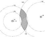
図4を参照して、これをLiDAR94とインフラセンサ80について考える。ここでは、レーザ光が到達可能で、光が戻ってくることがある範囲を伝搬範囲といい、伝搬範囲内で物体までの距離を高い信頼性で測定できる範囲を解析範囲という。伝搬範囲は解析範囲の外側領域であり、解析範囲を含まない。図4に示すように、LiDAR94は、LiDAR94を中心とする円形の領域である伝搬範囲104と、同じくLiDAR94を中心とする伝搬範囲104よりも小さな半径の円形である解析範囲106とを持つ。インフラセンサ80のLiDARは、インフラセンサ80を中心とする円形の伝搬範囲100と、インフラセンサ80を中心とし伝搬範囲100よりも小さな半径の円形の解析範囲102とを持つ。図4に示す例では、伝搬範囲100及び解析範囲102はそれぞれ伝搬範囲104及び解析範囲106より大きいが、伝搬範囲及び解析範囲はセンサごとに異なるので図4に示す例には限らない。
This will be considered for the
なお、図3に示すように車両84がインフラセンサ80に向かって走行している場合、車両84がインフラセンサ80に十分に近くなると、図4の斜線領域で示すように、伝搬範囲100と伝搬範囲104の重複領域であって解析範囲106にも解析範囲102にも含まれない部分(この明細書では、この領域108を、伝搬範囲のみが重複している領域という意味で重複領域という。)が生じる。エッジサーバ70による解析では、図5に示すように解析範囲106及び解析範囲102内の物体から得られた点群データのみを解析して物体の検出を行うため、解析範囲106内又は解析範囲102内にある物体は検出できるが、図5において点線で示すように、伝搬範囲104内にある物体、伝搬範囲100内にある物体、及び重複領域108内にある物体は検出されない。
When the
しかし、前述したとおり、重複領域108内の物体からでもLiDAR94に反射光が帰ってくる場合もあるし、同様にインフラセンサ80に反射光が帰ってくる場合もある。LiDAR94及びインフラセンサ80は、これら信頼性の低い点群データは廃棄する。したがってこれら反射光から得られる点群データはエッジサーバ70では使用されない。しかし、両者は同じ領域に存在する物体からの反射光を受光しているので、LiDAR94が重複領域108内の物体から受光した反射光と、インフラセンサ80が重複領域108内の物体から受光した反射光とを総合して解析すれば、図6に示すように重複領域108内に存在する物体も検出できる可能性がある。この実施の形態では、こうした考え方によりLiDAR94及びインフラセンサ80からはそれぞれ伝搬範囲104及び伝搬範囲100内の物体から得られた点群データもエッジサーバ70に送信する。この明細書では、図6に示すように車両に搭載されたセンサとインフラセンサとの点群データを統合して処理することが可能な領域(重複領域108)が生ずるような位置(センサから一定距離内の位置)に車両が存在することを「(車両が)インフラ協調エリア内に存在している」という。すなわち、車両センサがインフラ協調エリア内に存在する場合には、センサによる物体の検出範囲を適応的に広げることで単独のセンサでは検出できない物体も検出できる可能性を高くする。
However, as described above, the reflected light may be returned to the
エッジサーバ70は、これら点群データの中で、解析範囲106内の点群データ及び解析範囲102内の点群データと、重複領域108内の点群データとを統合して点群データの解析を行い物体の検出を行う。
Among these point cloud data, the
なお、図5及び図6に示すグリッド130は、エッジサーバ70が点群データの解析の際に使用するものである。この実施の形態では、LiDAR94及びインフラセンサ80からそれぞれの位置データと、伝搬範囲104及び解析範囲106、並びに伝搬範囲100及び解析範囲102に関する情報をそれぞれ受信し、伝搬範囲104及び伝搬範囲100を包含する最小のグリッドを形成する。グリッドにより区画される矩形をここではセルという。エッジサーバ70は各セルにLiDAR94及びインフラセンサ80から受信した点群データをマッピングしてデータの解析を行う。
The
なお、グリッドは様々な方法で形成できる。この実施の形態では、予め所定の大きさのセルである広さの領域をグリッド化しておき、伝搬範囲104及び伝搬範囲100に関する情報を受けた時点でそれらを包含する最小のグリッドを選択するものとする。
The grid can be formed by various methods. In this embodiment, a region having a size that is a cell of a predetermined size is gridded in advance, and when information about the
《車両側の設備》
図7を参照して、車両84は、LiDAR94、車載カメラ142、及びミリ波レーダ140等の各種のセンサ、及びこれらセンサからセンサデータを収集しエッジサーバ70に無線通信により送信するための車載装置146と、を含む。
《Vehicle side equipment》
With reference to FIG. 7, the
図8を参照して、車載装置146は実質的にはコンピュータ160を含むプロセッサであって、マイクロプロセッサ180、マイクロプロセッサ180とコンピュータ160内の各部との間のデータ及び命令の伝送経路となるバス190とを含む。コンピュータ160はさらに、いずれもバス190に接続されたROM(Read−Only Memory)182、RAM(Random Access Memory)184、ハードディスク又はSSD(Solid State Drive)等からなる不揮発性の補助記憶装置186、無線通信により外部との通信を提供する無線通信部188、入出力インターフェイス(I/F)192及びユーザとの音声によるインタラクションを提供するための音声処理I/F194とを含む。
With reference to FIG. 8, the in-
車載装置146はさらに、バス190に接続されたタッチパネル164、液晶等のモニタ162、及び入出力I/F192に接続された車両の制御のための各種アクチュエータ166及びLiDAR94等の各種センサ168と、音声処理I/F194に接続されたスピーカ及びマイク170と、バス190に接続され、USBメモリ172が装着可能で、コンピュータ160の各部とUSBメモリ172との間のデータの授受を行う半導体メモリドライブ196とを含む。ROM182にはコンピュータ160の起動プログラム等が記憶されている。RAM184はマイクロプロセッサ180による処理の際に様々な変数を記憶するための作業領域として使用される。
The in-
図9に、車載装置146のマイクロプロセッサ180が実行する、センサデータのエッジサーバ70へのアップロード機能を実現するプログラムの制御構造を示す。このプログラムは、補助記憶装置186に記憶されており、車載装置146が起動するとRAM184にロードされ、マイクロプロセッサ180により実行される。図9を参照して、このプログラムは、起動後、アップロードのタイミングか否かを判定するステップ210と、ステップ210の判定でアップロードのタイミングではないと判定されたときに所定時間だけ待機し、所定時間経過後に制御をステップ210に戻すステップ212と、ステップ210においてアップロードのタイミングであると判定されたことに応答して、センサデータである点群データと、センサ情報とをエッジサーバ70にアップロードし、制御をステップ210に戻すステップ214とを含む。この明細書において、センサ情報とは、センサの位置を示す情報(位置情報)、センサの伝搬範囲104及び解析範囲106を示す情報のことをいう。なお、センサデータには現在時刻を示す情報(時刻情報)も含まれる。アップロードされるセンサデータとしてはLiDAR94が検出した点群データ以外にも、車載カメラ142による画像データ、ミリ波レーダ140による検出データ等があるが、これらの動作サイクルは互いに異なっているため、図9のステップ214ではLiDAR94による点群データのみをエッジサーバ70にアップロードし、他のセンサデータは別のタイミングでエッジサーバ70にアップロードするものとする。
FIG. 9 shows a control structure of a program executed by the
図9に制御構造を示すプログラムにより、所定時間ごとにLiDAR94の点群データがエッジサーバ70に送信される。
The program showing the control structure in FIG. 9 transmits the point cloud data of LiDAR94 to the
《インフラセンサ80》
インフラセンサ80の構成を図10に示す。図10を参照して、このインフラセンサ80は、カメラ232及びLiDAR234と、カメラ232からの画像データ及びLiDAR234からの点群データを、LiDAR234の位置情報とともにエッジサーバ70に送信するためのインフラセンサ情報送信装置230とを含む。
<<
The configuration of the
図11に、インフラセンサ情報送信装置230のハードウェア構成を示す。図11を参照して、インフラセンサ情報送信装置230も実質的にはコンピュータ250を含むプロセッサである。コンピュータ250は、マイクロプロセッサ280と、マイクロプロセッサ280及びコンピュータ250内の各機能部との間のデータ及び命令の経路となるバス290とを含む。コンピュータ250はさらに、いずれもバス290に接続された、ROM282と、RAM284と、ハードディスク又はSSD等からなる不揮発性の補助記憶装置286と、無線通信により外部との通信を提供する無線通信部288と、入出力I/F292とを含む。
FIG. 11 shows the hardware configuration of the infrastructure sensor
インフラセンサ情報送信装置230はさらに、入出力I/F292に接続された、カメラ232及びLiDAR234を含む各種センサ252を含む。
The infrastructure
図12に、インフラセンサ情報送信装置230がセンサデータをエッジサーバ70にアップロードするよう、マイクロプロセッサ280を機能させるためのコンピュータプログラムの制御構造を示す。このプログラムは、補助記憶装置286に記憶されており、インフラセンサ情報送信装置230が起動すると補助記憶装置286からRAM284にロードされマイクロプロセッサ280により実行される。
FIG. 12 shows a control structure of a computer program for operating the
図12を参照して、このプログラムは、インフラセンサ情報送信装置230の起動後、アップロードのタイミングか否かを判定するステップ310と、ステップ310の判定でアップロードのタイミングではないと判定されたときに所定時間だけ待機し、所定時間経過後に制御をステップ310に戻すステップ312と、ステップ310においてアップロードのタイミングであると判定されたことに応答して、LiDAR234のセンサデータである点群データと、LiDAR234の位置情報、LiDAR234の伝搬範囲100及び解析範囲102を示すセンサ情報をエッジサーバ70にアップロードし、制御をステップ310に戻すステップ314とを含む。なお、ここでもステップ314でエッジサーバ70にアップロードされるのは、センサデータの中でLiDAR234からの点群データのみであり、カメラ232による画像データは別のプログラムで別のタイミングでエッジサーバ70に送信される。ここでもセンサデータには現在時刻を示す情報が含まれる。
With reference to FIG. 12, when this program starts the infrastructure sensor
図12に制御構造を示すプログラムにより、所定時間ごとにLiDAR234の点群データがエッジサーバ70に送信される。
The program showing the control structure in FIG. 12 transmits the point cloud data of LiDAR234 to the
《エッジサーバ70》
―機能的構成―
図13を参照して、エッジサーバ70は、インフラセンサ80及びLiDAR94等からセンサ情報及びセンサデータを、車両及びインフラセンサからそれぞれの位置情報を、それぞれ受信する受信処理部340と、受信処理部340が受信した信号の中で、LiDAR等から受信した点群データ等の受信データを一時記憶するための受信データ記憶部342と、受信データ記憶部342に記憶された受信データの中の各センサの伝搬範囲及び解析範囲についての情報を用いてグリッドマップを作成し初期化するグリッドマップ作成部344と、グリッドマップ作成部344により作成されたグリッドマップの各セルに関する情報を記憶するグリッドマップ記憶部346とを含む。グリッドマップとは、地上のある地域をグリッドに分割したもののことをいう。ある地域を包括的に含むグリッドマップをグローバルグリッドと呼ぶ。グローバルグリッドは複数のセルに分割される。各セルは基本的には正方形であり、その一辺は所望の解像度にあわせた大きさに決められる。交通支援に使用されるグリッドは、例えば一辺が30cmのセルからなる。通常、グローバルグリッドの各辺は経度線及び緯度線に並行になるように選択される。
<<
-Functional configuration-
With reference to FIG. 13, the
エッジサーバ70はさらに、グリッドマップ作成部344により作成されたグリッドの各セルの中で、解析の対象となるセルのリストを記憶するための対象セルリスト記憶部350と、所定時間ごとに、受信データ記憶部342に記憶された点群データを読出し、その位置データにしたがって各点群データをグリッドマップの各セルにマッピングする点群データマッピング部348と、対象セルリスト記憶部350を参照して、グリッドマップ記憶部346に記憶されたグリッドマップの各セルの中で、解析処理の対象となるセルを判定する対象セル判定部352とを含む。
The
エッジサーバ70はさらに、対象セル判定部352により対象セルと判定されたセルの点群データのみをグリッドマップ記憶部346から読出して解析し、処理対象(解析範囲106、解析範囲102、及び重複領域108を統合した範囲の動体)を検出する処理を行う動体検出部354と、動体検出部354により検出された動体に関するデータを記憶する検出動体記憶部356とを含む。
Further, the
グリッドマップ記憶部346はグリッドマップ作成部344及び点群データマッピング部348により一定時間ごとに作り変えられるので、動体検出部354による解析結果は、各タイミングでの動体の位置等となる。しかし過去の一定時間に算出された解析結果もそれぞれ履歴として検出動体記憶部356に蓄積され記憶されている。
Since the grid
エッジサーバ70はさらに、検出動体記憶部356に記憶されている現在及び過去の動体の位置データを解析して動体を追跡する動体追跡部358と、動体追跡部358による解析結果を記憶する解析結果記憶部360と、検出動体記憶部356に記憶されているデータに基づいて各動体の属性を検出する属性検出部362と、属性検出部362により検出された各動体の属性を記憶する解析結果記憶部364と、解析結果記憶部360に記憶されている動体の位置に関するデータと解析結果記憶部364に記憶されている各動体の属性とを統合する統合処理部366と、統合処理部366により統合された解析結果を記憶する解析結果記憶部368とを含む。
The
エッジサーバ70はさらに、受信処理部340が各車両から受信した信号に基づいて、管理対象の車両の位置、速度及び移動方向等からなる車両情報を得るための車両追跡部380と、車両追跡部380により解析された各車両の位置、速度及び移動方向等の車両情報を記憶するための車両情報記憶部382とを含む。エッジサーバ70はさらに、解析結果記憶部368に記憶された各動体の位置、属性、及び動き等に関する動体情報と、車両情報記憶部382とを照合し、統合後の動体情報において子供、スマートフォンを見ながら歩行する歩行者等のような、危険と思われる属性を持つ動的物体、道路上の事故車両、故障車両、落下物等についての情報等の交通支援のための情報を、当該物体から所定範囲内に位置する車両に対して報知する等の処理を行う情報送信部390と、情報送信部390による情報報知のための信号を無線通信により対象車両に送信するための送信処理部392とを含む。なお、図13では送信処理部392は受信処理部340とは別の機能ブロックとなっているが、受信処理部340及び送信処理部392は同じハードウェアを使用してもよい。
The
―ハードウェア構成―
エッジサーバ70は、この実施の形態では、コンピュータハードウェア及び当該コンピュータハードウェア上で実行されるコンピュータプログラムにより実現される。図14はエッジサーバ70のためのコンピュータハードウェアのブロック図を示す。図14を参照して、エッジサーバ70は、インターネット450に接続されるコンピュータ440と、いずれもコンピュータ440に接続されたモニタ442、キーボード446及びマウス448とを含む。モニタ442はタッチパネルでもよく、キーボード446及びマウス448は、モニタ442上でソフトウェアにより実現されてもよい。
-Hardware configuration-
In this embodiment, the
コンピュータ440はマイクロプロセッサ460と、マイクロプロセッサ460とコンピュータ440内の各部との間のデータ及び命令の伝送経路となるバス474とを含む。コンピュータ440はさらに、いずれもバス474に接続された、並列処理により大量のデータを高速に処理可能なGPU(Graphical Processing Unit)462、ROM464、RAM468、ハードディスク又はSSD等からなる不揮発性の補助記憶装置470、DVD(Digital Versatile Disc)452が装着可能なDVDドライブ472、インターネット450への接続を提供するネットワークI/F476、及び無線通信により外部との通信を提供する無線通信部478を含む。
The
―エッジサーバ70を実現するプログラムの構成―
図15に、エッジサーバ70においてLiDARからの点群データを統合する処理を実現するプログラムの構成をフローチャート形式で示す。このプログラムは、グリッドマップを作り直すタイミングに合わせ、交通状況俯瞰マップを作成するプログラムと並列に、一定時間間隔で繰返し動作する。図15を参照して、このプログラムは、処理対象となっている車両がインフラ協調エリアを走行中か否かを判定し、判定にしたがって制御の流れを分岐させるステップ500を含む。ステップ500の判定が否定であればステップ506に進み、LiDAR94からの点群データとインフラセンサ80からの点群データとを別々に、従来と同様の手法を用いて解析しプログラムの実行を終了する。
-Program configuration to realize the edge server 70-
FIG. 15 shows the configuration of a program that realizes the process of integrating the point cloud data from LiDAR in the
このプログラムはさらに、ステップ500の判定が肯定であることに応答して、車両センサとインフラセンサとの共通グリッドマップを作成し最適化するステップ502と、ステップ502により作成されたグリッドマップを使用してセンサデータを解析し、解析後のデータを使用して各車両に対して情報を送信して処理を終了するステップ504とを含む。
The program also uses the grid map created by
図16に、図15のステップ502で実行されるプログラムの詳細なフローチャートを示す。図16を参照して、このプログラムは、車両センサ及びインフラセンサの各々の伝搬範囲及び解析範囲を図13に示す受信データ記憶部342から読出すステップ550と、ステップ550で読出したデータに基づき、予め準備されたグローバルなグリッドの中で車両センサ及びインフラセンサの両方の伝搬範囲を包含する最小のグリッドを決定することで統合グリッドを生成するステップ552と、ステップ552で生成された統合グリッドの各セルに対応する要素を持つ配列を生成するステップ554と、統合処理の対象となる対象セルのリストを初期化するステップ556とを含む。
FIG. 16 shows a detailed flowchart of the program executed in
このプログラムはさらに、図13に示す受信データ記憶部342に記憶されている各点群データの各々について、以下の処理560を実行するステップ558を含む。
The program further includes step 558 for executing the following
処理560は、処理対象となっている点群データを、その位置データに基づいてステップ552で生成されたグリッドのいずれかにマッピングするステップ570と、ステップ570で点群データがマッピングされたグリッドのセルを表す情報を対象セルのリストに追加するステップ572とを含む。ステップ570では、各点群データを、その位置を含むグリッドセルにマッピングする。ステップ572のリストは、既にリスト内に存在するセルが再度追加されたときには新たなセルを追加することはしない形式のものが好ましい。
The
このプログラムはさらに、ステップ558に続き、ステップ572で作成された処理対象セルのリスト内の各セルについて、以下の処理564を実行するステップ562を含む。
The program further includes, following step 558,
処理564は、処理対象となっているセルがインフラセンサの解析範囲内か否かを判定し、判定にしたがって制御の流れを分岐させるステップ580と、ステップ580の判定結果が否定であるときに、処理対象となっているセルが車両センサの解析範囲内か否かを判定し、判定にしたがって制御の流れを分岐させるステップ582と、ステップ582の判定が否定のときに、処理対象となっているセルがインフラセンサの伝搬範囲内か否かを判定し、判定にしたがって制御の流れを分岐させるステップ584と、ステップ584の判定が肯定であることに応答して、処理対象となっているセルが車両センサの伝搬範囲内か否かを判定し、判定にしたがって制御の流れを分岐させるステップ586と、ステップ584の判定結果が否定のとき、及びステップ586の判定が否定のときに、処理対象のセルを対象セルのリストから削除し処理564を終了するステップ588とを含む。ステップ580の判定が肯定のとき、ステップ582の判定が肯定のとき、ステップ584の判定が肯定でかつステップ586の判定が肯定のときには、処理対象セルのリストに対する処理はせず処理564の処理を終了する。
The
すなわち、処理対象のセルがインフラセンサの解析範囲内にあるか、車両センサの解析範囲内にあるとき、及び、処理対象のセルがインフラセンサの伝搬範囲内にあり、かつ、車両センサの伝搬範囲内にもあるとき、すなわち両者の重複した範囲にあるときには、そのセルについては解析の処理対象とする。それ以外のときには処理対象とはしない。 That is, when the cell to be processed is within the analysis range of the infrastructure sensor or within the analysis range of the vehicle sensor, and the cell to be processed is within the propagation range of the infrastructure sensor and the propagation range of the vehicle sensor. When it is also inside, that is, when it is in the overlapping range of both, the cell is processed for analysis. In other cases, it is not processed.
このような構成をとることにより、以下のような効果が生じる。すなわち、統合グリッドの大きさは伝搬範囲と比較して大きく、含まれるセルの数も多い。そのため、統合グリッド内の全てのセルについて、処理対象とすべきか否かを判定していると、処理に要する時間が長くなるおそれがある。それに対しこの実施の形態では、点群データがあるセルにマッピングされるたびに、そのセルを示すデータを対象セルのリストに追加する。さらに、対象セルの中でも上記した条件を充足しないセルは削除される。点群データを解析するときには、処理対象セルのリストにあるセルだけを処理対象とすればよい。この処理対象セルのリストは統合グリッド全体に含まれるセルの数以下であり、多くの場合にはかなり少なくなることが見込まれる。したがって、統合グリッドにマッピングされた点群データに対する解析処理を短時間で終了させることができる。 By adopting such a configuration, the following effects are produced. That is, the size of the integrated grid is large compared to the propagation range, and the number of cells included is also large. Therefore, if it is determined whether or not all the cells in the integrated grid should be processed, the time required for processing may become long. On the other hand, in this embodiment, every time the point cloud data is mapped to a certain cell, the data indicating the cell is added to the list of target cells. Further, among the target cells, cells that do not satisfy the above conditions are deleted. When analyzing the point cloud data, only the cells in the list of cells to be processed need to be processed. This list of cells to be processed is less than or equal to the number of cells contained in the entire integration grid, and is expected to be considerably smaller in many cases. Therefore, the analysis process for the point cloud data mapped to the integrated grid can be completed in a short time.
〈動作〉
上記したシステムは以下のように動作する。図3を参照して、車両84はLiDAR94により得られた伝搬範囲の点群データを全てエッジサーバ70に送信する(図9)。同様にインフラセンサ80もLiDARの伝搬範囲から得られた点群データを全てエッジサーバ70に送信する(図12)。
<motion>
The above system operates as follows. With reference to FIG. 3, the
車両84がインフラセンサ80から離れた位置(インフラ協調エリア外)にある場合、図4の重複領域108のような領域は生じない。図15を参照して、この場合、受信データ記憶部342(図13)がこれらデータを受信した後、ステップ502及びステップ504の処理は行われない。図13に示すグリッドマップ作成部344は車両84とインフラセンサ80との双方について別々にグリッドマップを作成する。動体検出部354はこのグリッドマップを使用して動体検出を行う。検出された動体に関する情報は検出動体記憶部356に記憶され、動体追跡部358が各動体を追跡し、属性検出部362が各動体の属性を検出する。これら情報はそれぞれ解析結果記憶部360及び解析結果記憶部364に記憶された後、統合処理部366により統合され解析結果記憶部368に記憶される。一方、エッジサーバ70は受信処理部340を介して車両情報を受信し、車両追跡部380が各車両を追跡する。各車両の位置等に関する情報は車両情報記憶部382に記憶される。情報送信部390は解析結果記憶部368に記憶された解析結果に基づいて作成した交通支援の情報を、車両情報記憶部382に記憶された各車両に向けて送信処理部392を介して送信する。
When the
一方、図3を参照して、車両が十分にインフラセンサ80に近づき、インフラ協調エリアに進入したとする。この場合、図4に示すようにLiDAR94の伝搬範囲104とインフラセンサ80の伝搬範囲100との間に重複領域108が生ずる。
On the other hand, with reference to FIG. 3, it is assumed that the vehicle has sufficiently approached the
この場合、図15に示すプログラムでステップ500の判定が肯定となり、ステップ502が実行される。
In this case, in the program shown in FIG. 15, the determination in
図13を参照して、グリッドマップ作成部344は車両84のLiDAR94及びインフラセンサ80のLiDARの伝搬範囲及び解析範囲を受信データ記憶部342から読出す(図16のステップ550)。続いてグリッドマップ作成部344はグリッドマップ記憶部346に記憶されている前回作成したグリッドマップをクリアし、新たなグリッドマップを作成してグリッドマップ記憶部346に記憶させる(図16のステップ552)。このグリッドマップは、グリッドマップ作成部344が予め記憶しているグローバルグリッドマップから、LiDAR94の伝搬範囲とインフラセンサ80のLiDARの伝搬範囲とを包含する最も小さな矩形からなる部分的なグリッドマップを特定することで作成される。さらにグリッドマップ作成部344はグリッドマップ記憶部346内に、グリッドマップの各セルを要素とする二次元配列を作成する(図16のステップ554)。さらにグリッドマップ作成部344は、対象セルリスト記憶部350に記憶された対象セルのリストを初期化する(図16のステップ556)。この初期化は、要素が何もないリストを生成することに相当する。
With reference to FIG. 13, the grid
点群データマッピング部348は、受信データ記憶部342に記憶されている点群データを読出す(図16のステップ558)。点群データマッピング部348は、読出した各点群データを、それらの位置に基づいてグリッドマップの各セルにマッピングし、対応する配列要素に記憶させる(図16のステップ570)。同時に点群データマッピング部348は、ある配列要素に点群データをマッピングしたときには、その配列要素を特定する情報を対象セルリスト記憶部350に追加する(図16のステップ572)。対象セルリスト記憶部350は、このセルを記憶する。ただし、対象セルリスト記憶部350は、既にリスト内にあるセルの追加要求があった場合にはその要求を無視する。
The point cloud
この処理をすることにより、LiDAR94からの点群データ及びインフラセンサ80からの点群データが全てグリッドマップ上にマッピングされる。
By performing this processing, all the point cloud data from the
ステップ558の処理560が全て完了すると、図13に示す対象セル判定部352が、グリッドマップ記憶部346に記憶されているグリッドマップの中で、どのセルを処理対象とすべきかについて対象セルリスト記憶部350を参照して以下のように判定する。
When all the
すなわち、図16を参照して、ステップ552において、対象セルリスト記憶部350に記憶された対象セルリスト内の各セルについて、まずそのセルがインフラセンサ80の解析範囲内にあるか否かを判定する。判定結果が肯定ならこのセルは処理対象となる。判定結果が否定なら制御はステップ582に進む。
That is, with reference to FIG. 16, in
ステップ582では、セルは車両センサであるLiDAR94の解析範囲内か否かを判定する。判定が肯定ならこのセルは処理対象となる。判定が否定なら制御はステップ584に進む。
In
ステップ584ではセルがインフラセンサ80の伝搬範囲内か否かが判定される。判定が肯定なら制御はステップ586に進み、さらにセルがLiDAR94の伝搬範囲内か否かが判定される。ステップ586の判定が肯定ならこのセルは処理対象となる。ステップ584での判定が否定の場合、及びステップ586での判定が否定の場合には、セルを処理対象セルのリストから削除する。
In
すなわち、セルがインフラセンサ80の解析範囲内にあるか、LiDAR94の解析範囲内にあるか、又はセルがインフラセンサ80の伝搬範囲内にあってかつLiDAR94の伝搬範囲内にある場合にはそのセルは処理対象となり、それ以外のセルは処理対象から除外される。
That is, if the cell is within the analysis range of the
このようにすることで、点群データに対する解析では、対象セルリスト内のセルのみを処理対象とすればよく、グリッドマップ内の全セルを処理対象とする必要がなくなる。その結果、点群データに対する処理が速くなるという効果が生じる。 By doing so, in the analysis of the point cloud data, only the cells in the target cell list need to be processed, and it is not necessary to process all the cells in the grid map. As a result, there is an effect that the processing for the point cloud data becomes faster.
動体検出部354は、グリッドマップ記憶部346に記憶されているグリッドマップのセルの中で、対象セルリスト記憶部350に記憶されたリスト内のセルの点群データのみを解析対象として解析を行い、動体を検出する。検出された動体に関する情報は検出動体記憶部356に記憶される。以下の処理は車両がインフラ協調エリア外にある場合と同じである。
The
以上のようにこの実施の形態に係る交通支援システムによれば、LiDAR94及びインフラセンサ80の伝搬範囲内の点群データという、従来は使用されていなかったデータを使用して動体の検出を行うことができる。従来は検出されていなかった動体を検出できる可能性が高くなり、より充実した交通支援情報を交通参加者に対して提供できる。また、グリッドマップにマッピングされた点群データの中で、LiDAR94の伝搬範囲とインフラセンサ80の伝搬範囲との重複領域から検出された点群データのみを処理対象とする。そのため、伝搬範囲まで処理対象を広げても処理時間が大きく増加することはなく、従来と同じ周期で繰返すことが可能であり、より充実した交通支援情報を提供できる。
As described above, according to the traffic support system according to this embodiment, the moving object is detected by using the point cloud data within the propagation range of the
なお、インフラセンサ80は固定した位置に設けられている。したがって、インフラセンサ80の位置並びに伝搬範囲及び解析範囲に関する情報が予め分かっている場合には、エッジサーバ70にその情報を記憶しておけばよい。例えばインフラセンサ80の位置にエッジサーバ70を設置するような場合が考えられる。
The
<第2の実施の形態>
〈構成〉
上記第1の実施の形態に係る交通支援システムでは、LiDAR94の伝搬範囲とインフラセンサ80の伝搬範囲とが多少とも重複していればインフラ協調処理を行っている。しかし、この開示の実施の形態はそのような形態には限定されない。重複領域がごく小さい場合には、重複領域の点群データを用いても有効な情報が得られない可能性が高い。そもそも重複領域から点群データが得られない可能性もある。そこで、LiDAR94の伝搬範囲とインフラセンサ80の伝搬範囲との重複領域の面積があるしきい値より大きい場合に限ってインフラ協調処理を行う事が考えられる。第2の実施の形態に係る交通支援システムはそのようなシステムである。
<Second Embodiment>
<Constitution>
In the traffic support system according to the first embodiment, if the propagation range of the
この実施の形態に係るシステムでは、図13の対象セル判定部352を実現するプログラムが第1の実施の形態のものとは異なっている。そのプログラムの制御構造を図17にフローチャート形式で示す。図17に示すフローチャートが図16に示すものと異なっているのは、図16のステップ562に替えて、対象セルリスト内の各セルについて処理602を実行するステップ600を含む点である。
In the system according to this embodiment, the program for realizing the target
処理602が図16に示す処理564と異なるのは、ステップ582の判定が否定となったとき、ステップ584の前に、伝搬範囲の重複領域の面積がしきい値より大きいか否かを判定し、判定が肯定のときに制御をステップ584に進め、それ以外のときには制御をステップ588に進めるステップ610を含む点である。それ以外の点では図17の処理602は図16の処理564と同一であり、図17の全体フローチャートは図16の全体フローチャートと同一である。
The
〈動作〉
この第2の実施の形態に係る交通支援システムでは、図17の処理602に示すように、対象セルリスト内のセルがインフラセンサ80の解析範囲内になく(ステップ580でNO)、かつそのセルがLiDAR94の解析範囲内にもない場合(ステップ582でNO)には、インフラセンサ80の伝搬範囲とLiDAR94の伝搬範囲との重複領域の面積がしきい値より大きいか否かが判定される。重複領域の面積がしきい値以下であれば(ステップ610の判定がNO)重複領域を含め、伝搬領域内の点群データは処理対象とされない。重複領域の面積がしきい値より大きいときのみ、重複領域内の点群データが処理対象となる。
<motion>
In the traffic support system according to the second embodiment, as shown in the
以上のようにこの第2の実施の形態によれば、LiDAR94とインフラセンサ80の伝搬範囲の重複領域の面積がしきい値より大きくなければ、重複領域から得られた点群データは動体検出のための解析対象とならない。重複領域の点群データから有効な情報が得られる可能性が高いときのみ、重複領域から得られた点群データを処理対象とするので、交通支援情報の品質を落とさず、処理を高速化できる。
As described above, according to the second embodiment, if the area of the overlapping region of the propagation range of the
なお、この実施の形態では伝搬範囲の重複領域の面積がしきい値より大きい場合にのみ伝搬範囲の重複領域内にあるセルを解析の処理対象としている。しかしこの開示の実施の形態はそのような形態には限定されない。例えば、図17のステップ584において、2つのセンサの少なくとも一方の検出精度がしきい値より高いと判定されたときに、伝搬範囲の重複領域を解析の処理対象としてもよい。このために必要な構成は次の第3の実施の形態の構成と類似しているのでここでは詳細は述べない。
In this embodiment, the cells in the overlapping area of the propagation range are targeted for analysis only when the area of the overlapping area of the propagation range is larger than the threshold value. However, the embodiments of this disclosure are not limited to such embodiments. For example, in
このように少なくとも一方のセンサの検出精度が高いときには、伝搬範囲の情報についても、多少の情報を補完することで正しい物体の検出を行うことができる可能性が高い。そうした場合に、他のセンサの伝搬範囲の重複領域の情報を使用することで、単独では検出できない物体を検出できる可能性が高くなる。 When the detection accuracy of at least one of the sensors is high as described above, it is highly possible that the correct object can be detected by supplementing some information with respect to the information of the propagation range. In such a case, by using the information of the overlapping region of the propagation range of other sensors, it is highly possible that an object that cannot be detected by itself can be detected.
<第3の実施の形態>
〈構成〉
第1の実施の形態では、エッジサーバ70はインフラセンサ80及び車両84のLiDAR94の双方からセンサの伝搬範囲及び解析範囲に関する情報を受信している。しかしこの開示の実施の形態はそのような形態には限定されない。予めエッジサーバ70にセンサごとに伝搬範囲及び解析範囲に関する情報をセンサの識別情報とともに記憶しておき、各センサからはそのセンサの識別情報を受信するようにしてもよい。この第3の実施の形態に係るエッジサーバ630はそのような機能を持つ。
<Third embodiment>
<Constitution>
In the first embodiment, the
図18に、第3の実施の形態に係るエッジサーバ630の機能ブロック図を示す。図18を参照して、このエッジサーバ630が図13に示すエッジサーバ70と異なるのは、センサの伝搬範囲及び解析範囲に関する情報をセンサの識別情報(品番等)と関連付けて記憶したセンサ情報記憶部640、及び受信データ記憶部342からLiDAR94及びインフラセンサ80のセンサ識別情報を読出し、センサ情報記憶部640からそれらの伝搬範囲及び解析範囲に関する情報を読出すセンサ情報読出部642を新たに含むことと、図13のグリッドマップ作成部344に替えて、センサ情報読出部642の出力する各センサの伝搬範囲及び解析範囲に関する情報を用いてグリッドマップ記憶部346にグリッドマップを作成するグリッドマップ作成部646を含むこととである。その他の点ではエッジサーバ630は図13に示すエッジサーバ70と同一である。
FIG. 18 shows a functional block diagram of the
〈動作〉
この第3の実施の形態に係るエッジサーバ630では、最初にグリッドマップを作成するときの動作のみが第1の実施の形態のエッジサーバ70と異なる。すなわち、受信処理部340はLiDAR94及びインフラセンサ80からそれぞれの点群データ及び位置データとともに、センサの識別情報を受信しいずれも受信データ記憶部342に格納する。センサ情報読出部642は、グリッドマップ作成のタイミングになると受信データ記憶部342から各センサの識別情報を読出し、各識別情報をキーにセンサ情報記憶部640から各センサの伝搬範囲及び解析範囲に関する情報を読出す。グリッドマップ作成部646はセンサ情報読出部642が読出した各センサの伝搬範囲及び解析範囲に関する情報と、受信データ記憶部342に格納されている各センサの位置データとを用いて、グリッドマップ記憶部346内のグリッドマップを作成しなおす。このグリッドマップの作成方法は第1の実施の形態のグリッドマップ作成部344によるものと同一である。
<motion>
The
この実施の形態に係るエッジサーバ630では、各センサから伝搬範囲及び解析範囲に関する情報を受信せず、各センサの識別情報を受信するだけでその伝搬範囲及び解析範囲を特定できる。その結果、各センサから送信する情報を削減しながら第1の実施の形態と同様、より有効な交通支援情報を提供できる。
The
なおセンサ情報記憶部640はエッジサーバ630の内部に存在する必要はない。センサ情報記憶部640を外部のサーバに保存し、外部からその識別情報をキーに伝搬範囲と解析範囲とがセンサごとに読出すことができるのであれば、それを利用しても良い。識別情報としては、センサの品番だけでもよいし、センサのメーカとメーカごとのセンサの品番とをあわせて用いることもできる。
The sensor
なお、第2の実施の形態の末尾で述べたように、センサごとの物体検出精度に基づいて重複領域を解析対象とするか否かを決定するシステムの場合には、図18に示す構成において、センサ情報記憶部640にセンサの物体検出精度を記憶させておき、センサ情報読出部642によりその精度を読出すようにすればよい。
As described at the end of the second embodiment, in the case of a system that determines whether or not the overlapping region is to be analyzed based on the object detection accuracy of each sensor, the configuration shown in FIG. 18 is used. The sensor
<第4の実施の形態>
〈構成〉
上記第2の実施の形態では、LiDAR94及びインフラセンサ80の伝搬範囲の重複領域の面積がしきい値より大きいときに重複領域内の点群データを動体解析の対象としている。しかしこの開示の実施の形態はそのような形態には限定されない。LiDAR94を搭載した車両84の速度がしきい値より大きいときのみ、LiDAR94の伝搬範囲とインフラセンサ80の伝搬範囲との重複領域の点群データを動体解析の対象としてもよい。第4の実施の形態はそのような実施の形態である。なお、この実施の形態では、2つのセンサが一定の速さ以上の速さで互いに近づいているときのみ伝搬範囲の重複領域を解析の対象とする。
<Fourth Embodiment>
<Constitution>
In the second embodiment, when the area of the overlapping region of the propagation range of the
図19は、第1の実施の形態に係る図16に示すものに替えて、この第4の実施の形態に係るエッジサーバで実行されるプログラムのフローチャートである。図19に示すフローチャートが図16に示すフローチャートと異なるのは、図16のステップ562に替えて、対象セルリスト内の各セルに対して処理670を実行するステップ660を含む点である。その他の点では図19に示すフローチャートは図16に示すものと同一である。
FIG. 19 is a flowchart of a program executed by the edge server according to the fourth embodiment instead of the one shown in FIG. 16 according to the first embodiment. The flowchart shown in FIG. 19 differs from the flowchart shown in FIG. 16 in that it includes
一方、処理670が図16の処理564と異なるのは、ステップ582の判定が否定のとき、ステップ584の前に、LiDAR94とインフラセンサ80との間の距離の減少速度が所定のしきい値(>0)より大きいか否かを判定し、判定が肯定であるときには制御をステップ584に、判定が否定であるときには制御をステップ588に、それぞれ分岐させるステップ680を含む点である。その他の点では処理670は図16に示す処理564と同一である。
On the other hand, the
〈動作〉
この第4の実施の形態に係る交通支援システムでは、図19の処理670に示すように、対象セルリスト内のセルがインフラセンサ80の解析範囲内になく(ステップ580でNO)、かつそのセルがLiDAR94の解析範囲内にもない場合(ステップ582でNO)には、LiDAR94とインフラセンサ80の間の距離の減少速度が正のしきい値より大きいか否かが判定される。この減少速度がしきい値以下であれば(ステップ680の判定がNO)重複領域を含め、伝搬領域内の点群データは処理対象とされない。センサ間の距離の減少速度がしきい値より大きいときのみ、重複領域内の点群データが処理対象となる。
<motion>
In the traffic support system according to the fourth embodiment, as shown in the
この第4の実施の形態によれば、LiDAR94とインフラセンサ80の間の距離の減少速度がしきい値より大きくなければ、重複領域から得られた点群データは動体検出のための解析対象とならない。LiDAR94とインフラセンサ80の間の距離の減少速度がしきい値より大きいということは、インフラセンサ80が固定されていることを前提とすれば、LiDAR94がインフラセンサ80に近づいており、かつその速度がしきい値より大きいことを意味する。こうした場合には、LiDAR94を搭載した車両84に、より充実した交通支援情報を提供することが可能になる。一方、ステップ680の条件が充足されないときには、重複領域の点群データを処理対象としないので、解析処理に要する時間を短縮化できる。その結果、センサの伝搬範囲の重複領域から得られた点群データを用いてより詳細な交通支援情報を提供でき、さらに、そのように詳細な交通支援情報が不要な場合には処理を高速化できるという効果がある。
According to this fourth embodiment, if the rate of decrease in the distance between the
[コンピュータによる実現]
本開示の上記実施の形態に係る交通支援システムで使用される車載装置146、インフラセンサ情報送信装置230、エッジサーバ70、630等は、図8、図11及び図14に示すように、コンピュータハードウェアと、そのコンピュータハードウェア内のマイクロプロセッサにより実行されるプログラムとにより実現される。これらプログラムの構成の中で、この発明に関係するものについては図9、図12、図15〜図17及び図19に示したとおりである。これらプログラムを、図8に示す補助記憶装置186、図11に示す補助記憶装置286、及び図14に示す補助記憶装置470に記憶しておき、実行時には図8に示すRAM184、図11に示すRAM284、及び図14に示すRAM468にそれぞれロードし、図8に示すマイクロプロセッサ180、図11に示すマイクロプロセッサ280、及び図14に示すマイクロプロセッサ460に実行させることにより、上記した各実施の形態に係る交通支援システムを実現できる。
[Realization by computer]
The in-
これらのプログラムは、コンピュータに上記各実施形態に係る車載装置146、インフラセンサ情報送信装置230、エッジサーバ70及び630等として動作を行わせる複数の命令を含む。この動作を行わせるのに必要な基本的機能のいくつかはコンピュータ上で動作するオペレーティングシステム(OS)若しくはサードパーティのプログラム、又は各コンピュータにインストールされる各種ツールキットのモジュールにより提供される。したがって、このプログラムはこの実施形態のシステム及び方法を実現するのに必要な機能全てを必ずしも含まなくてよい。このプログラムは、命令の中で、所望の結果が得られるように制御されたやり方で適切な機能又は「プログラミング・ツール・キット」を呼出すことにより、上記した車載装置146、インフラセンサ情報送信装置230、エッジサーバ70及び630等並びにその構成要素としての動作を実行する命令のみを含んでいればよい。コンピュータの動作は周知であるので、ここでは繰返さない。なお、図14に示すGPU462は並列処理を行うことが可能であり、多くの動体検出のための処理を同時並列的に実行する際に有効に機能する。
These programs include a plurality of instructions for causing the computer to operate as the in-
上記実施の形態では、センサの伝搬範囲と解析範囲とがセンサごとに固定されたものとして説明した。しかしこの開示の実施の形態はそのような形態には限定されない。例えばLiDAR等の場合、レーザ光を使用する関係上、周囲の環境によって検出精度がしきい値以上となる距離が変動する可能性がある。例えば物体から反射してくる光の強さを測定することでその距離の変動をある程度検知できる。そうした場合には、各センサでその変動に合わせて伝搬範囲と解析範囲とを動的に変更することも可能である。そうした場合にも、上記した実施の形態の中で、センサから伝搬範囲及び解析範囲に関する情報を受け取るシステムでは、それら変動にあわせて解析対象の範囲を変化させることが可能である。 In the above embodiment, it has been described that the propagation range and the analysis range of the sensor are fixed for each sensor. However, the embodiments of this disclosure are not limited to such embodiments. For example, in the case of LiDAR or the like, since the laser beam is used, the distance at which the detection accuracy becomes equal to or higher than the threshold value may vary depending on the surrounding environment. For example, by measuring the intensity of light reflected from an object, fluctuations in the distance can be detected to some extent. In such a case, it is possible for each sensor to dynamically change the propagation range and the analysis range according to the fluctuation. Even in such a case, in the above-described embodiment, in the system that receives information on the propagation range and the analysis range from the sensor, it is possible to change the range of the analysis target according to these fluctuations.
さらに、上記実施の形態では、2つのセンサの一方が動体に設置され、他方が路側に設置されているものとして説明した。しかしこの開示の実施形態はそのような形態には限定されない。例えば双方のセンサがいずれも動体に設置されている場合でもよい。この場合には、双方のセンサからエッジサーバに位置情報を送信することが必要である。また、双方のセンサとも固定されている場合でもこの開示は適用できる。この場合には、双方のセンサの位置が固定され、伝搬範囲及び解析範囲も予めわかるので、これらの情報を予めエッジサーバに記憶させておけば、センサからエッジサーバには点群データと時刻情報のみを送信すればよい。 Further, in the above embodiment, it has been described that one of the two sensors is installed on the moving body and the other is installed on the roadside. However, the embodiments of this disclosure are not limited to such embodiments. For example, both sensors may be installed on a moving object. In this case, it is necessary to transmit the position information from both sensors to the edge server. Also, this disclosure is applicable even when both sensors are fixed. In this case, the positions of both sensors are fixed, and the propagation range and analysis range are known in advance. Therefore, if these information are stored in the edge server in advance, the point cloud data and time information can be stored from the sensor to the edge server. You only have to send.
また上記実施の形態では、サーバが装置全体を回転させて周囲をスキャンする機械式LiDARであるものとして説明した。しかしこの開示の実施形態はそのような形態には限定されない。LiDARとしてはこのような方式のものに限らず、ポリゴンミラーを用いてレーザ光で周囲をスキャンするもの、MEMS(Micro Electro Mechanical Systems)ミラーを使用してスキャンするもの、レーザを2次元的に配置した2次元アレーによるもの、単一のレーザ光の発射方向を電子的に偏向させることで2次元的に空間をスキャンするもの、及びそれらを複数個組み合わせるもの等、任意のものを用いることができる。同様に、近赤外線ではなく、ミリ波のパルスを用いるミリ波レーダについてもこの発明を適用できる。原理的にはテラヘルツ波によるレーダを用いても良い。また、上記実施の形態では、対象となるセンサデータは点群データであるものとした。しかしこの開示の実施形態はそのような形態には限定されない。 Further, in the above embodiment, it has been described that the server is a mechanical LiDAR that rotates the entire device and scans the surroundings. However, the embodiments of this disclosure are not limited to such embodiments. LiDAR is not limited to this type, but one that scans the surroundings with a laser beam using a polygon mirror, one that scans using a MEMS (Micro Electro Mechanical Systems) mirror, and one in which a laser is arranged two-dimensionally. Any one can be used, such as a two-dimensional array, one that scans the space two-dimensionally by electronically deflecting the emission direction of a single laser beam, and one that combines a plurality of them. .. Similarly, the present invention can be applied to millimeter wave radars that use millimeter wave pulses instead of near infrared rays. In principle, a radar using a terahertz wave may be used. Further, in the above embodiment, the target sensor data is assumed to be point cloud data. However, the embodiments of this disclosure are not limited to such embodiments.
上記交通支援システムにおける各装置は、図8、図11及び図14に示すように、マイクロプロセッサ、ROM、RAM等を含んで構成されるコンピュータを備える。マイクロプロセッサ等の演算処理部は、図12、図15から図17及び図19に示すような、シーケンス図またはフローチャートの各ステップの一部または全部を含むコンピュータプログラムを、ROM、RAM等の記憶部からそれぞれ読み出して実行する。これら複数の装置のコンピュータプログラムは、それぞれ、外部のサーバ装置等からインストールすることができる。また、これら複数の装置のコンピュータプログラムは、それぞれ、CD−ROM、DVD−ROM、半導体メモリ等の記録媒体に格納された状態で流通する。 As shown in FIGS. 8, 11 and 14, each device in the traffic support system includes a computer including a microprocessor, a ROM, a RAM, and the like. An arithmetic processing unit such as a microprocessor stores a computer program including a part or all of each step of a sequence diagram or a flowchart as shown in FIGS. 12, 15 to 17 and 19 in a storage unit such as a ROM or RAM. Read from each and execute. The computer programs of these plurality of devices can be installed from an external server device or the like. Further, the computer programs of these plurality of devices are distributed in a state of being stored in a recording medium such as a CD-ROM, a DVD-ROM, or a semiconductor memory, respectively.
今回開示された実施の形態は単に例示であって、この発明が上記した実施の形態のみに制限されるわけではない。この開示の範囲は、発明の詳細な説明の記載を参酌した上で、特許請求の範囲の各請求項によって示され、そこに記載された文言と均等の意味及び範囲内での全ての変更を含む。 The embodiments disclosed this time are merely examples, and the present invention is not limited to the above-described embodiments. The scope of this disclosure is indicated by each claim of the claims, taking into account the description of the detailed description of the invention, and all changes within the meaning and scope equivalent to the wording described therein. Including.
50 実空間
52 交通状況俯瞰マップ
70、630 エッジサーバ
72 基地局
80 インフラセンサ
82、84 車両
92、94、234 LiDAR
100、104 伝搬範囲
102、106 解析範囲
108 重複領域
130 グリッド
140 ミリ波レーダ
142 車載カメラ
146 車載装置
160、250、440 コンピュータ
162、442 モニタ
164 タッチパネル
166 各種アクチュエータ
168、252 各種センサ
170 スピーカ及びマイク
172 USBメモリ
180、280、460 マイクロプロセッサ
182、282、464 ROM
184、284、468 RAM
186、286、470 補助記憶装置
188、288、478 無線通信部
190、290、474 バス
192、292 入出力I/F
194 音声処理I/F
196 半導体メモリドライブ
210、212、214、310、312、314、500、502、504、506、550、552、554、556、558、562、570、572、580、582、584、586、588、600、610、660、680 ステップ
230 インフラセンサ情報送信装置
232 カメラ
340 受信処理部
342 受信データ記憶部
344、646 グリッドマップ作成部
346 グリッドマップ記憶部
348 点群データマッピング部
350 対象セルリスト記憶部
352 対象セル判定部
354 動体検出部
356 検出動体記憶部
358 動体追跡部
360、364、368 解析結果記憶部
362 属性検出部
366 統合処理部
380 車両追跡部
382 車両情報記憶部
390 情報送信部
392 送信処理部
446 キーボード
448 マウス
450 インターネット
452 DVD
462 GPU
472 DVDドライブ
476 ネットワークI/F
560、564、602、670 処理
640 センサ情報記憶部
642 センサ情報読出部
50
100, 104
184, 284, 468 RAM
186, 286, 470
194 Speech processing I / F
196 Semiconductor memory drives 210, 212, 214, 310, 312, 314, 500, 502, 504, 506, 550, 552, 554, 556, 558, 562, 570, 57, 580, 582, 584, 586, 588, 600, 610, 660, 680
462 GPU
472
560, 564, 602, 670
Claims (12)
前記第1のセンサ及び前記第2のセンサの各々は、当該センサの周囲の所定領域内にある物体までの距離を表すセンサデータを取得可能であり、かつ、前記所定領域は、当該センサによる物体の検出の信頼度がしきい値より高い第1の領域と、信頼度が前記しきい値以下の第2の領域とに区分され、
前記第1のセンサ及び前記第2のセンサの前記第1の領域及び前記第2の領域を特定するための情報を取得する領域情報取得部と、
前記領域情報取得部により取得された前記情報に基づき、前記第1のセンサ及び前記第2のセンサの各々の前記第1の領域と、前記第1のセンサ及び前記第2のセンサの各々の前記第2の領域の重複領域とを統合することにより、適応的な統合検出範囲を特定する検出範囲適応装置と、
前記第1のセンサ及び前記第2のセンサから、当該第1のセンサ及び前記第2のセンサがそれぞれ得た、各センサの検出範囲内のセンサデータを取得し、前記統合検出範囲にマッピングするマッピング装置と、
前記マッピング装置により前記統合検出範囲にマッピングされたセンサデータを解析することにより、前記統合検出範囲内にある物体を検出する解析装置とを含む、物体検出装置。 An object detection device that detects an object based on the outputs of the first sensor and the second sensor.
Each of the first sensor and the second sensor can acquire sensor data representing a distance to an object in a predetermined area around the sensor, and the predetermined area is an object by the sensor. It is divided into a first region where the reliability of detection is higher than the threshold value and a second region where the reliability is lower than the threshold value.
A region information acquisition unit that acquires information for identifying the first region and the second region of the first sensor and the second sensor, and
Based on the information acquired by the area information acquisition unit, the first area of each of the first sensor and the second sensor, and the said of each of the first sensor and the second sensor. A detection range adaptor that identifies an adaptive integrated detection range by integrating with the overlapping area of the second region.
Mapping that acquires sensor data within the detection range of each sensor obtained by the first sensor and the second sensor from the first sensor and the second sensor, and maps them to the integrated detection range. With the device
An object detection device including an analysis device that detects an object within the integrated detection range by analyzing sensor data mapped to the integrated detection range by the mapping device.
前記領域情報取得部は、
前記第1のセンサの前記第1の領域と前記第2の領域とを特定する情報を取得する第1のセンサ情報取得部と、
前記第2のセンサの前記第1の領域と前記第2の領域とを特定する情報を取得する第2のセンサ情報取得部とを含み、
前記解析装置による解析後に前記統合検出範囲及び当該統合検出範囲にマッピングされた点群データをクリアするクリア部と、
前記第1のセンサ情報取得部、前記第2のセンサ情報取得部、前記検出範囲適応装置、前記マッピング装置、前記解析装置、及び前記クリア部を所定時間ごとに繰返し動作させることにより、前記統合検出範囲内にある物体を前記所定時間ごとに継続的に検出する検出制御部とをさらに含む、請求項1に記載の物体検出装置。 The sensor data includes point cloud data representing the distance from each of the first sensor and the second sensor to an object in a predetermined surrounding area.
The area information acquisition unit
A first sensor information acquisition unit that acquires information that identifies the first region and the second region of the first sensor, and
Includes a second sensor information acquisition unit that acquires information that identifies the first region and the second region of the second sensor.
A clear unit that clears the integrated detection range and the point cloud data mapped to the integrated detection range after analysis by the analysis device.
The integrated detection is performed by repeatedly operating the first sensor information acquisition unit, the second sensor information acquisition unit, the detection range adaptation device, the mapping device, the analysis device, and the clear unit at predetermined time intervals. The object detection device according to claim 1, further comprising a detection control unit that continuously detects an object within the range at predetermined time intervals.
センサの識別情報ごとに、当該センサに関する前記第1の領域及び前記第2の領域を特定する領域特定情報を記憶する領域特定情報記憶装置と、
前記第1のセンサ及び前記第2のセンサの各々から、当該センサの位置、及び当該センサの識別情報を取得するセンサ識別情報取得部と、
前記第1のセンサ及び前記第2のセンサの各々について、前記領域特定情報記憶装置から前記センサ識別情報取得部が取得した識別情報に対応する領域特定情報を読出し、前記センサ識別情報取得部が取得した当該センサの位置と当該領域特定情報とを用いて、当該センサの前記第1の領域及び前記第2の領域の範囲を算出する範囲算出装置とを含む、請求項1又は請求項2に記載の物体検出装置。 The area information acquisition unit
An area-specific information storage device that stores area-specific information that specifies the first area and the second area related to the sensor for each sensor identification information.
A sensor identification information acquisition unit that acquires the position of the sensor and the identification information of the sensor from each of the first sensor and the second sensor.
For each of the first sensor and the second sensor, the area identification information corresponding to the identification information acquired by the sensor identification information acquisition unit is read from the area identification information storage device, and the sensor identification information acquisition unit acquires the area identification information. The first or second aspect of the invention, which includes a range calculation device for calculating the range of the first region and the second region of the sensor by using the position of the sensor and the region identification information. Object detection device.
センサの識別情報ごとに、当該センサに関する物体検出精度を記憶する検出精度記憶装置と、
前記第1のセンサ及び前記第2のセンサの各々から、当該センサの位置、及び当該センサの識別情報を取得するセンサ識別情報取得部と、
前記第1のセンサ及び前記第2のセンサの各々について、前記検出精度記憶装置から前記センサ識別情報取得部が取得した識別情報に対応する物体検出精度を読出す精度読出装置と、
前記第1のセンサ及び前記第2のセンサの少なくとも一方の物体検出精度が所定のしきい値より大きいことに応答して、前記領域情報取得部により取得された前記情報に基づき、前記第1のセンサ及び前記第2のセンサの前記第1の領域と、前記第1のセンサ及び前記第2のセンサの前記第2の領域の重複領域とを統合することにより、前記統合検出範囲を特定する第1の統合範囲特定装置と、
前記第1のセンサ及び前記第2のセンサの双方の物体検出精度がいずれも前記所定のしきい値以下であることに応答して、前記領域情報取得部により取得された前記情報に基づき、前記第1のセンサ及び前記第2のセンサの各々の前記第1の領域を統合することにより、前記統合検出範囲を特定する第2の統合範囲特定装置とを含む、請求項1又は請求項2に記載の物体検出装置。 The area information acquisition unit
A detection accuracy storage device that stores the object detection accuracy of the sensor for each sensor identification information,
A sensor identification information acquisition unit that acquires the position of the sensor and the identification information of the sensor from each of the first sensor and the second sensor.
An accuracy reading device that reads the object detection accuracy corresponding to the identification information acquired by the sensor identification information acquisition unit from the detection accuracy storage device for each of the first sensor and the second sensor.
The first sensor is based on the information acquired by the area information acquisition unit in response to the object detection accuracy of at least one of the first sensor and the second sensor being greater than a predetermined threshold value. The integrated detection range is specified by integrating the first region of the sensor and the second sensor with the overlapping region of the second region of the first sensor and the second sensor. 1 integrated range identification device and
Based on the information acquired by the area information acquisition unit in response to the object detection accuracy of both the first sensor and the second sensor being equal to or less than the predetermined threshold value, the said The first or second aspect of the present invention includes a second integrated range specifying device that specifies the integrated detection range by integrating the first region of each of the first sensor and the second sensor. The object detection device described.
前記検出範囲適応装置は、
前記第1のセンサの移動速度が所定のしきい値より大きいことに応答して、前記領域情報取得部により取得された前記情報に基づき、前記第1のセンサ及び前記第2のセンサの前記第1の領域と、前記第1のセンサ及び前記第2のセンサの前記第2の領域の重複領域とを統合することにより、前記統合検出範囲を特定する第1の統合範囲特定装置と、
前記第1のセンサの移動速度が前記所定のしきい値以下であることに応答して、前記領域情報取得部により取得された前記情報に基づき、前記第1のセンサ及び前記第2のセンサの各々の前記第1の領域を統合することにより、前記統合検出範囲を特定する第2の統合範囲特定装置とを含む、請求項2に記載の物体検出装置。 The first sensor information acquisition unit further acquires the moving speed of the first sensor.
The detection range adapting device is
In response to the movement speed of the first sensor being greater than a predetermined threshold value, the first sensor and the second sensor of the first sensor and the second sensor are based on the information acquired by the area information acquisition unit. A first integrated range specifying device that specifies the integrated detection range by integrating the region 1 and the overlapping region of the second region of the first sensor and the second sensor.
In response to the movement speed of the first sensor being equal to or less than the predetermined threshold value, the first sensor and the second sensor are based on the information acquired by the region information acquisition unit. The object detection device according to claim 2, further comprising a second integrated range specifying device that specifies the integrated detection range by integrating each of the first areas.
前記領域情報取得部により取得された前記情報に基づき、前記第1のセンサの前記第2の領域と、前記第2のセンサの前記第2の領域との重複領域を算出する重複領域算出部と、
前記重複領域算出部により算出された前記重複領域の面積が所定のしきい値より大きいことに応答して、前記第1のセンサ及び前記第2のセンサの各々の前記第1の領域と、前記第1のセンサ及び前記第2のセンサの前記第2の領域の重複領域とを統合することにより、適応的な統合検出範囲を特定する第1の統合範囲特定装置と、
前記重複領域の面積が前記所定のしきい値以下であることに応答して、前記第1のセンサ及び前記第2のセンサの各々の前記第1の領域を統合することにより、適応的な統合検出範囲を特定する第2の統合範囲特定装置とを含む、請求項1〜請求項4のいずれか1項に記載の物体検出装置。 The detection range adapting device is
An overlapping area calculation unit that calculates an overlapping area between the second area of the first sensor and the second area of the second sensor based on the information acquired by the area information acquisition unit. ,
In response to the area of the overlapping region calculated by the overlapping region calculation unit being larger than a predetermined threshold value, the first region of each of the first sensor and the second sensor, and the said. A first integrated range identification device that identifies an adaptive integrated detection range by integrating the first sensor and the overlapping area of the second area of the second sensor.
Adaptive integration by integrating the first region of each of the first sensor and the second sensor in response that the area of the overlapping region is less than or equal to the predetermined threshold. The object detection device according to any one of claims 1 to 4, which includes a second integrated range identification device for specifying a detection range.
当該物体検出装置による解析により得られる交通支援情報を前記管理領域内に存在する交通参加者に送信する送信装置とを含む、交通支援サーバ。 The object detection device according to any one of claims 1 to 7, for detecting and analyzing an object existing in a predetermined control area.
A traffic support server including a transmission device that transmits traffic support information obtained by analysis by the object detection device to traffic participants existing in the management area.
前記第1のセンサ及び前記第2のセンサの各々は、当該センサの周囲の所定領域内にある物体までの距離を表すセンサデータを取得可能であり、かつ、前記所定領域は、物体の検出の信頼度がしきい値より高い第1の領域と、信頼度が前記しきい値以下の第2の領域とに区分され、
前記第1のセンサ及び前記第2のセンサの前記第1の領域及び前記第2の領域を特定するための情報を前記第1のセンサ及び前記第2のセンサからそれぞれ取得するステップと、
前記取得するステップにおいて取得された前記情報に基づき、前記第1のセンサ及び前記第2のセンサの各々の前記第1の領域と、前記第1のセンサ及び前記第2のセンサの前記第2の領域の重複領域とを統合することにより、適応的な統合検出範囲を特定するステップと、
前記第1のセンサ及び前記第2のセンサから、前記第1のセンサ及び前記第2のセンサがそれぞれ得た、各センサの検出範囲からのセンサデータを取得し、前記統合検出範囲にマッピングするステップと、
前記マッピングするステップにおいて前記統合検出範囲にマッピングされたセンサデータを解析することにより、前記統合検出範囲内にある物体を検出するステップとを含む、物体検出方法。 An object detection method for detecting an object based on the outputs of the first sensor and the second sensor.
Each of the first sensor and the second sensor can acquire sensor data representing a distance to an object within a predetermined area around the sensor, and the predetermined area is for detecting an object. It is divided into a first region whose reliability is higher than the threshold value and a second region whose reliability is lower than the threshold value.
A step of acquiring information for identifying the first region and the second region of the first sensor and the second sensor from the first sensor and the second sensor, respectively.
Based on the information acquired in the acquisition step, the first region of each of the first sensor and the second sensor, and the second of the first sensor and the second sensor. Steps to identify adaptive integrated detection ranges by integrating with overlapping regions of the region,
A step of acquiring sensor data from the detection range of each sensor obtained by the first sensor and the second sensor from the first sensor and the second sensor, and mapping them to the integrated detection range. When,
An object detection method including a step of detecting an object within the integrated detection range by analyzing sensor data mapped to the integrated detection range in the mapping step.
前記第1のセンサ及び前記第2のセンサの各々は、当該センサの周囲の所定領域内にある物体までの距離を表すセンサデータを取得可能であり、かつ、前記所定領域は、当該センサによる物体の検出の信頼度がしきい値より高い第1の領域と、信頼度が前記しきい値以下の第2の領域とに区分され、
前記コンピュータプログラムは、コンピュータを、
前記第1のセンサ及び前記第2のセンサの前記第1の領域及び前記第2の領域を特定するための情報を取得する領域情報取得部と、
前記領域情報取得部により取得された前記情報に基づき、前記第1のセンサ及び前記第2のセンサの各々の前記第1の領域と、前記第1のセンサ及び前記第2のセンサの各々の前記第2の領域の重複領域とを統合することにより、適応的な統合検出範囲を特定する検出範囲適応装置と、
前記第1のセンサ及び前記第2のセンサから、当該第1のセンサ及び前記第2のセンサがそれぞれ得た、各センサの検出範囲内のセンサデータを取得し、前記統合検出範囲にマッピングするマッピング装置と、
前記マッピング装置により前記統合検出範囲にマッピングされたセンサデータを解析することにより、前記統合検出範囲内にある物体を検出する解析装置として機能させる、コンピュータプログラム。 A computer program that causes a computer to function as an object detection device that detects an object based on the outputs of the first sensor and the second sensor.
Each of the first sensor and the second sensor can acquire sensor data representing a distance to an object in a predetermined area around the sensor, and the predetermined area is an object by the sensor. It is divided into a first region where the reliability of detection is higher than the threshold value and a second region where the reliability is lower than the threshold value.
The computer program is a computer
A region information acquisition unit that acquires information for identifying the first region and the second region of the first sensor and the second sensor, and
Based on the information acquired by the area information acquisition unit, the first area of each of the first sensor and the second sensor, and the said of each of the first sensor and the second sensor. A detection range adaptor that identifies an adaptive integrated detection range by integrating with the overlapping area of the second region.
Mapping that acquires sensor data within the detection range of each sensor obtained by the first sensor and the second sensor from the first sensor and the second sensor, and maps them to the integrated detection range. With the device
A computer program that functions as an analysis device that detects an object within the integrated detection range by analyzing sensor data mapped to the integrated detection range by the mapping device.
前記センサの前記第1の領域及び前記第2の領域を特定するための領域特定情報を記憶する領域特定情報記憶部と、
前記領域特定情報記憶部に記憶された前記領域特定情報と、前記センサにより前記第1の領域及び前記第2の領域の双方から取得されたセンサデータとを所定のサーバに送信する送信装置とを含む、センサ装置。 It is possible to acquire sensor data representing the distance to an object in a predetermined surrounding area, and the predetermined area is reliable with a first area in which the reliability of detection of the object by the sensor is higher than the threshold value. A sensor whose degree is divided into a second region below the threshold value,
An area-specific information storage unit that stores area-specific information for specifying the first area and the second area of the sensor, and
A transmission device that transmits the area identification information stored in the area identification information storage unit and the sensor data acquired by the sensor from both the first area and the second area to a predetermined server. Including sensor device.
Priority Applications (1)
| Application Number | Priority Date | Filing Date | Title |
|---|---|---|---|
| JP2019054105A JP2020154913A (en) | 2019-03-22 | 2019-03-22 | Object detection devices and methods, traffic support servers, computer programs and sensor devices |
Applications Claiming Priority (1)
| Application Number | Priority Date | Filing Date | Title |
|---|---|---|---|
| JP2019054105A JP2020154913A (en) | 2019-03-22 | 2019-03-22 | Object detection devices and methods, traffic support servers, computer programs and sensor devices |
Publications (1)
| Publication Number | Publication Date |
|---|---|
| JP2020154913A true JP2020154913A (en) | 2020-09-24 |
Family
ID=72559387
Family Applications (1)
| Application Number | Title | Priority Date | Filing Date |
|---|---|---|---|
| JP2019054105A Pending JP2020154913A (en) | 2019-03-22 | 2019-03-22 | Object detection devices and methods, traffic support servers, computer programs and sensor devices |
Country Status (1)
| Country | Link |
|---|---|
| JP (1) | JP2020154913A (en) |
Cited By (3)
| Publication number | Priority date | Publication date | Assignee | Title |
|---|---|---|---|---|
| JP2021193562A (en) * | 2020-06-05 | 2021-12-23 | フォルクスヴァーゲン アクチエンゲゼルシャフトVolkswagen Aktiengesellschaft | Vehicle, method, computer program, and device for merging object information about one or more objects around vehicle |
| WO2022059486A1 (en) | 2020-09-15 | 2022-03-24 | 三井化学株式会社 | Powder cosmetic and cosmetic composition |
| CN115981173A (en) * | 2022-12-05 | 2023-04-18 | 歌尔股份有限公司 | Device control method, terminal device, and storage medium |
-
2019
- 2019-03-22 JP JP2019054105A patent/JP2020154913A/en active Pending
Cited By (5)
| Publication number | Priority date | Publication date | Assignee | Title |
|---|---|---|---|---|
| JP2021193562A (en) * | 2020-06-05 | 2021-12-23 | フォルクスヴァーゲン アクチエンゲゼルシャフトVolkswagen Aktiengesellschaft | Vehicle, method, computer program, and device for merging object information about one or more objects around vehicle |
| JP7150938B2 (en) | 2020-06-05 | 2022-10-11 | フォルクスヴァーゲン アクチエンゲゼルシャフト | Vehicle, method, computer program and apparatus for merging object information about one or more objects in vehicle surroundings |
| US12087157B2 (en) | 2020-06-05 | 2024-09-10 | Volkswagen Aktiengesellschaft | Vehicle, method, computer program and device for merging object information about one or more objects in the surroundings of a vehicle |
| WO2022059486A1 (en) | 2020-09-15 | 2022-03-24 | 三井化学株式会社 | Powder cosmetic and cosmetic composition |
| CN115981173A (en) * | 2022-12-05 | 2023-04-18 | 歌尔股份有限公司 | Device control method, terminal device, and storage medium |
Similar Documents
| Publication | Publication Date | Title |
|---|---|---|
| EP3812793B1 (en) | Information processing method, system and equipment, and computer storage medium | |
| US11016500B2 (en) | Simulation-based method to evaluate perception requirement for autonomous driving vehicles | |
| CN108427123B (en) | LIDAR device and method for operating a LIDAR device | |
| US10551840B2 (en) | Planning driven perception system for autonomous driving vehicles | |
| US10031526B1 (en) | Vision-based driving scenario generator for autonomous driving simulation | |
| US10262234B2 (en) | Automatically collecting training data for object recognition with 3D lidar and localization | |
| US10520319B2 (en) | Data driven map updating system for autonomous driving vehicles | |
| US12222457B2 (en) | LIDAR system design to mitigate LIDAR cross-talk | |
| CN107015559B (en) | Probabilistic inference of target tracking using hash weighted integration and summation | |
| US11260880B2 (en) | Map-less and localization-less lane following method for autonomous driving of autonomous driving vehicles on highway | |
| JP2021051057A (en) | Method and apparatus for detecting ground point cloud point | |
| US10860868B2 (en) | Lane post-processing in an autonomous driving vehicle | |
| JP2022513866A (en) | Object classification using out-of-domain context | |
| US11971536B2 (en) | Dynamic matrix filter for vehicle image sensor | |
| US11221405B2 (en) | Extended perception based on radar communication of autonomous driving vehicles | |
| US10964048B2 (en) | Method and device for generating image for indicating object on periphery of vehicle | |
| JP2020154913A (en) | Object detection devices and methods, traffic support servers, computer programs and sensor devices | |
| US11372090B2 (en) | Light detection and range (LIDAR) device with SPAD and APD sensors for autonomous driving vehicles | |
| US11036225B2 (en) | Method for evaluating localization system of autonomous driving vehicles | |
| EP3906428B1 (en) | System, method, and components providing compressive active range sampling | |
| US11422260B2 (en) | Online lidar intensity normalization | |
| CN119068188A (en) | Dirt detection method and device for laser radar and autonomous driving vehicle | |
| HK40118847A (en) | Lidar contamination detection method, device, and autonomous vehicle | |
| KR20260039488A (en) | Vehicle electronic device and method for controlling vehicle using the same | |
| WO2022217522A1 (en) | Target sensing method and device, detection system, movable platform and storage medium |