JP2019526363A - Osteotome - Google Patents
Osteotome Download PDFInfo
- Publication number
- JP2019526363A JP2019526363A JP2019512712A JP2019512712A JP2019526363A JP 2019526363 A JP2019526363 A JP 2019526363A JP 2019512712 A JP2019512712 A JP 2019512712A JP 2019512712 A JP2019512712 A JP 2019512712A JP 2019526363 A JP2019526363 A JP 2019526363A
- Authority
- JP
- Japan
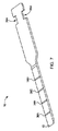
- Prior art keywords
- osteotome
- wing
- blade
- handle
- housing
- Prior art date
- Legal status (The legal status is an assumption and is not a legal conclusion. Google has not performed a legal analysis and makes no representation as to the accuracy of the status listed.)
- Granted
Links
Images




Classifications
-
- A—HUMAN NECESSITIES
- A61—MEDICAL OR VETERINARY SCIENCE; HYGIENE
- A61B—DIAGNOSIS; SURGERY; IDENTIFICATION
- A61B17/00—Surgical instruments, devices or methods
- A61B17/16—Instruments for performing osteoclasis; Drills or chisels for bones; Trepans
- A61B17/1604—Chisels; Rongeurs; Punches; Stamps
-
- A—HUMAN NECESSITIES
- A61—MEDICAL OR VETERINARY SCIENCE; HYGIENE
- A61B—DIAGNOSIS; SURGERY; IDENTIFICATION
- A61B17/00—Surgical instruments, devices or methods
- A61B17/56—Surgical instruments or methods for treatment of bones or joints; Devices specially adapted therefor
- A61B17/58—Surgical instruments or methods for treatment of bones or joints; Devices specially adapted therefor for osteosynthesis, e.g. bone plates, screws or setting implements
- A61B17/88—Osteosynthesis instruments; Methods or means for implanting or extracting internal or external fixation devices
- A61B17/92—Impactors or extractors, e.g. for removing intramedullary devices
-
- A—HUMAN NECESSITIES
- A61—MEDICAL OR VETERINARY SCIENCE; HYGIENE
- A61B—DIAGNOSIS; SURGERY; IDENTIFICATION
- A61B17/00—Surgical instruments, devices or methods
- A61B17/56—Surgical instruments or methods for treatment of bones or joints; Devices specially adapted therefor
- A61B17/58—Surgical instruments or methods for treatment of bones or joints; Devices specially adapted therefor for osteosynthesis, e.g. bone plates, screws or setting implements
- A61B17/88—Osteosynthesis instruments; Methods or means for implanting or extracting internal or external fixation devices
- A61B17/92—Impactors or extractors, e.g. for removing intramedullary devices
- A61B2017/922—Devices for impaction, impact element
-
- A—HUMAN NECESSITIES
- A61—MEDICAL OR VETERINARY SCIENCE; HYGIENE
- A61F—FILTERS IMPLANTABLE INTO BLOOD VESSELS; PROSTHESES; DEVICES PROVIDING PATENCY TO, OR PREVENTING COLLAPSING OF, TUBULAR STRUCTURES OF THE BODY, e.g. STENTS; ORTHOPAEDIC, NURSING OR CONTRACEPTIVE DEVICES; FOMENTATION; TREATMENT OR PROTECTION OF EYES OR EARS; BANDAGES, DRESSINGS OR ABSORBENT PADS; FIRST-AID KITS
- A61F2/00—Filters implantable into blood vessels; Prostheses, i.e. artificial substitutes or replacements for parts of the body; Appliances for connecting them with the body; Devices providing patency to, or preventing collapsing of, tubular structures of the body, e.g. stents
- A61F2/02—Prostheses implantable into the body
- A61F2/30—Joints
- A61F2/46—Special tools for implanting artificial joints
- A61F2/4603—Special tools for implanting artificial joints for insertion or extraction of endoprosthetic joints or of accessories thereof
- A61F2002/4619—Special tools for implanting artificial joints for insertion or extraction of endoprosthetic joints or of accessories thereof for extraction
Landscapes
- Health & Medical Sciences (AREA)
- Surgery (AREA)
- Life Sciences & Earth Sciences (AREA)
- Orthopedic Medicine & Surgery (AREA)
- Biomedical Technology (AREA)
- Nuclear Medicine, Radiotherapy & Molecular Imaging (AREA)
- Engineering & Computer Science (AREA)
- Heart & Thoracic Surgery (AREA)
- Medical Informatics (AREA)
- Molecular Biology (AREA)
- Animal Behavior & Ethology (AREA)
- General Health & Medical Sciences (AREA)
- Public Health (AREA)
- Veterinary Medicine (AREA)
- Oral & Maxillofacial Surgery (AREA)
- Dentistry (AREA)
- Surgical Instruments (AREA)
Abstract
医療装置インプラントを移植/引き抜くように構成されたオステオトームが提供される。オステオトームは、ハンドルと、ブレードを受容するためにハンドルの第1端部周りに設けられたブレード取り付けアセンブリと、第1端部の反対側のハンドルの第2端部周りに設けられたウイングアセンブリと、を有する。ウイングアセンブリは、さらに、ハンドルから外方に延出するウイングを有する。An osteotome configured to implant / withdraw a medical device implant is provided. The osteotome includes a handle, a blade mounting assembly provided around the first end of the handle for receiving the blade, and a wing assembly provided around the second end of the handle opposite the first end. Have. The wing assembly further has a wing extending outward from the handle.
Description
〔関連出願の相互参照〕
本出願は、ここにその全体を参考文献として合体させる2016年8月30日出願の米国仮出願第62/381381号の権利を主張するものである。
[Cross-reference of related applications]
This application claims the rights of US Provisional Application No. 62/381381, filed Aug. 30, 2016, which is hereby incorporated by reference in its entirety.
〔発明の背景〕
本開示の実施例は、一般に、医療装置インプラント引き抜きツールに関する。特に、本開示は、クイック解放可能なブレードとウイングアセンブリとを有するオステオトームに関する。
BACKGROUND OF THE INVENTION
Embodiments of the present disclosure generally relate to medical device implant extraction tools. In particular, the present disclosure relates to an osteotome having a quick releasable blade and a wing assembly.
インプラントを引き抜くときに、インプラントを骨から取り除くためまたは引き抜くために、オステオトームなどの医療装置インプラント引き抜きツールが利用される。オステオトームは、骨から医療インプラントを引き抜くために、骨の表面を成形したり骨を除去したりするために使用することが可能である。 When extracting the implant, a medical device implant extraction tool such as an osteotome is utilized to remove or extract the implant from the bone. The osteotome can be used to shape the bone surface or remove the bone in order to extract the medical implant from the bone.
従来のオステオトームは、その特定の構成により、その機能において限定されたものであり、結果としてインプラント引き抜きを容易にするための効果を損なっていた。したがって、医療装置インプラント引き抜き処置をよりよく補助するためのより効率的で経済的なオステオトームが未だ求められている。 The conventional osteotome is limited in its function due to its specific configuration, and as a result, the effect for facilitating the extraction of the implant is impaired. Therefore, there is still a need for a more efficient and economical osteotome to better assist the medical device implant extraction procedure.
本開示の実施例によれば、ハンドルと、ブレードを受容するべくハンドルの第1端部周りに設けられたブレード取り付けアセンブリと、第1端部の反対側のハンドルの第2端部周りに設けられたウイングアセンブリと、を有するオステオトームが提供される。ウイングアセンブリは、ハンドルから外方に延出するウイングを有する。 According to an embodiment of the present disclosure, a handle, a blade mounting assembly provided around the first end of the handle to receive the blade, and provided around the second end of the handle opposite the first end. And an osteotome having a structured wing assembly. The wing assembly has a wing extending outward from the handle.
実施例の一態様において、ウイングアセンブリは、ハンドルに揺動可能に取り付けられている。ウイングアセンブリは、さらに、ハウジングを有し、ウイングはハウジングに揺動可能に取り付けられている。ウイングアセンブリは、また、ハウジングに取り外し可能に取り付けられている。ハウジングは、当該ハウジングにウイングを受容するための凹部を有する。ウイングアセンブリは、さらに、ウイングを、ハンドルの長手軸心に対して固定位置に解放可能にロックするためのロック機構を有する。ロック機構は、ウイングから延出するデテントと、ハウジング周りの複数の対応するデテントと、を有する。デテントはタブであり、複数の対応するデテントはハウジング周りに周方向に配置された面取りエッジである。 In one aspect of the embodiment, the wing assembly is pivotally attached to the handle. The wing assembly further includes a housing, and the wing is swingably attached to the housing. The wing assembly is also removably attached to the housing. The housing has a recess for receiving a wing in the housing. The wing assembly further includes a locking mechanism for releasably locking the wing in a fixed position relative to the longitudinal axis of the handle. The locking mechanism has a detent extending from the wing and a plurality of corresponding detents around the housing. The detent is a tab and the corresponding detents are chamfered edges circumferentially arranged around the housing.
実施例の別態様において、ウイングはハンドルの長手軸心に対して垂直に延出するとともに、ハンドルの近位側端部に回転可能に固定されている。ウイングは、ハンドルに揺動可能に取り付けられた突出部材を有する。突出部材は、ハンドルと同軸である。突出部材は、ウイングをハウジングに固定するためのロック溝を有する。ロック溝は環状溝である。 In another aspect of the embodiment, the wing extends perpendicularly to the longitudinal axis of the handle and is rotatably fixed to the proximal end of the handle. The wing has a protruding member that is swingably attached to the handle. The protruding member is coaxial with the handle. The protruding member has a lock groove for fixing the wing to the housing. The lock groove is an annular groove.
実施例のさらに別の態様において、ブレード取り付けアセンブリは、ブレードを受容するためのハウジングと、ブレードをハウジングに解放可能に固定するためのロック機構とを有する。ハウジングは、ブレードを受容する凹部を有する。ロック機構はブレード側の一対のノッチに係合するための一対のデテントを有する。ロック機構は、ブレードを解放可能に固定するために、ロック位置と非ロック位置との間で移動する。オステオトームは、さらに、ロック機構をロック位置に向けて付勢する付勢部材を有する。付勢部材はバネである。 In yet another aspect of the embodiment, the blade mounting assembly has a housing for receiving the blade and a locking mechanism for releasably securing the blade to the housing. The housing has a recess for receiving the blade. The locking mechanism has a pair of detents for engaging the pair of notches on the blade side. The locking mechanism moves between a locked position and an unlocked position to releasably secure the blade. The osteotome further includes a biasing member that biases the lock mechanism toward the lock position. The biasing member is a spring.
実施例のさらに別の態様において、オステオトームは、さらに、ブレード取り付けアセンブリに解放可能に固定されるブレードを有する。ブレードは、このブレードをハンドルに対してアラインメントするための一対のノッチを有する。ブレードは、さらに、当該ブレード長さに沿って複数のインジケータを有する。ブレードは、さらに、斜角エッジを有する。 In yet another aspect of the embodiment, the osteotome further comprises a blade that is releasably secured to the blade mounting assembly. The blade has a pair of notches for aligning the blade with the handle. The blade further has a plurality of indicators along the blade length. The blade further has a beveled edge.
実施例のさらに別の態様において、ウイングは、ベースと、当該ベースから延出する延出部材と、当該延出部材から延出するインパクトプレートと、を有する。延出部材は、ハンドルの長手軸心に対して平行に延出する。インパクトプレートは、ハンドルの長手軸心から径方向外方に延出する。ウイングは、さらに、延出部材に揺動可能に取り付けられたガードを有する。ガードは、第1位置と第2位置との間で移動可能である。オステオトームは、さらに、ガードを固定位置に固定するためのロック部材を有する。 In yet another aspect of the embodiment, the wing includes a base, an extending member extending from the base, and an impact plate extending from the extending member. The extending member extends parallel to the longitudinal axis of the handle. The impact plate extends radially outward from the longitudinal axis of the handle. The wing further has a guard swingably attached to the extending member. The guard is movable between the first position and the second position. The osteotome further includes a locking member for fixing the guard in a fixed position.
本開示のその他の特徴および利点は、本開示の原理を例示的に図示する添付の図面を参照して、実施例に関する以下のより詳細な説明から明らかになるであろう。 Other features and advantages of the present disclosure will become apparent from the following more detailed description of the embodiments, taken in conjunction with the accompanying drawings which illustrate, by way of example, the principles of the disclosure.
以下の要約、さらに、本開示の実施例の以下の詳細説明は、添付の図面との関連において読まれることによってより良く理解されるであろう。本開示を図示する目的で、これらの図面には実施例が図示されている。ただし、本発明は、これらの厳密な構成と図示の装置構成とに限定されるものではない。 The following summary, as well as the following detailed description of embodiments of the present disclosure, will be better understood when read in conjunction with the appended drawings. For purposes of illustrating the present disclosure, examples are illustrated in these drawings. However, the present invention is not limited to these exact configurations and the illustrated apparatus configuration.
以下、添付の図面に図示されている本開示の種々の実施例について詳細に言及する。可能な場合は常に、図面全体を通じて、同じまたは類似の特徴構成に言及するために同じまたは類似の参照番号が使用される。なお、図面は簡略化されており、正確な縮尺で描かれたものではないことを銘記しなければならない。以下の説明において便宜上のみで、ある種の用語が使用されるが、これは非限定的なものである。上部、底部、右、左、上、下、対角方向などの方向の用語は、添付の図面との関連で使用される。用語「遠位側」は、体の中心から離れることを意味するものとする。用語「近位側」は、体の中心に近づく、または、「遠位側端部」から離間する、ことを意味するものとする。用語「内側」および「外側」は、それぞれ、指示された要素およびその指名された部分の幾何学的中心に向かう方向、およびそれから離間する方向を指す。図面の以下の説明との関連で使用されるそれらの方向に関する用語は、いかなるかたちにおいてもここに明示的には記載されていない本開示の範囲を限定するものと解釈されてはならない。さらに、本明細書に使用されている用語「a」は、「少なくとも一つ」を意味する。用語は、上に具体的に述べた単語、その派生形および類似の意味の単語を含む。 Reference will now be made in detail to various embodiments of the present disclosure that are illustrated in the accompanying drawings. Wherever possible, the same or similar reference numbers are used throughout the drawings to refer to the same or similar features. It should be noted that the drawings are simplified and are not drawn to scale. Certain terminology is used in the following description for convenience only and is not limiting. Directional terms such as top, bottom, right, left, top, bottom, diagonal are used in conjunction with the accompanying drawings. The term “distal” is intended to mean away from the center of the body. The term “proximal” shall mean approaching the center of the body or away from the “distal end”. The terms “inner” and “outer” refer to a direction toward and away from the geometric center of the indicated element and its designated portion, respectively. Terms for those orientations used in connection with the following description of the drawings should not be construed as limiting the scope of the present disclosure which is not expressly set forth herein in any way. Further, as used herein, the term “a” means “at least one”. The term includes the words specifically mentioned above, derivatives thereof and words of similar meaning.
ここで使用される「約」という用語は、持続時間などの量などの測定可能な値について言及する場合、それは、そのようなバリエーションが適切な場合、規定された値からの、±20%、±10%、±5%、±1%、または±0.1%、などのバリエーションを含むことを意味する。 As used herein, the term “about” refers to a measurable value, such as an amount such as duration, that is ± 20% from the specified value, if such variation is appropriate, It is meant to include variations such as ± 10%, ± 5%, ± 1%, or ± 0.1%.
本開示全体を通じて、本開示の様々な態様は範囲の形式で提供することができる。範囲の形式での記載は、単に便宜上および簡便性のためのものに過ぎず、実施例の範囲に対する硬直的な限定と解釈されてはならないことを銘記しなければならない。したがって、範囲の記載は、すべての可能な副範囲と、さらに、その範囲内での個々の数値とを開示したものとして解釈されるべきである。たとえば、1〜6などの範囲は、1〜3、1〜4、1〜5、2〜4、2〜6、3〜6、など、の副範囲と、さらに、たとえば、1、2、2.7、3、4、5、5.3および6などのその範囲内の個々の数字、を具体的に開示したものとして解釈されなければならない。これは、その範囲の幅に関わらず当てはまる。 Throughout this disclosure, various aspects of this disclosure can be provided in a range format. It should be noted that the description in range format is merely for convenience and convenience and should not be construed as an inflexible limitation on the scope of the examples. Accordingly, the description of a range should be construed as disclosing all possible subranges as well as individual numerical values within that range. For example, ranges such as 1 to 6 are subranges such as 1 to 3, 1 to 4, 1 to 5, 2 to 4, 2 to 6, 3 to 6, and further, for example, 1, 2, 2 Individual numbers within that range, such as 7, 3, 4, 5, 5.3 and 6, should be construed as specifically disclosing. This is true regardless of the width of the range.
さらに、本開示の実施例の記載される特徴、利点および特性は、単数または複数の実施例において任意の適当方法で組み合わせることが可能である。当業者はここでの記載から、特定の実施例の単数または複数の具体的特徴または利点無しで実施例を実施することが可能であることを認識するであろう。その他の場合において、本開示の全ての実施例に含まれないいくつかの実施例におけるその他の特徴および利点が認識されうる。 Furthermore, the described features, advantages, and characteristics of the embodiments of the present disclosure may be combined in any suitable manner in one or more embodiments. Those skilled in the art will appreciate from the description herein that embodiments can be practiced without the specific features or advantages of the particular embodiments. In other instances, other features and advantages may be recognized in some embodiments that are not included in all embodiments of the disclosure.
以下、本開示の対応が図示されている図面を参照すると、図1〜18は、一実施例によるオステオトーム10を図示している。オステオトーム10は、ハンドル12と、ブレード16を受容するべくハンドルの第1端部の周りに設けられたブレード取り付けアセンブリ14と、第1端部の反対側のハンドルの第2端部の周りに設けられたウイングアセンブリ18と、を有する。ウイングアセンブリ18は、ハンドル12から外方に延出するウイング20を有する。図1は、ハンドルから径方向外方に延出しているウイングを図示している。
Referring now to the drawings in which the correspondence of the present disclosure is illustrated, FIGS. 1-18 illustrate an
ハンドル12は、一般に、好ましくは剛直で、かつ、ユーザの手によって把持されるのに十分な大きさの長手部材である。図1に最も良く図示されているように、ハンドル12は、一般に、長手方向の中央軸心と実質的に円形の断面とを有する、実質的に筒状の部材である。ただし、ハンドル12は、六角形、多角形などの任意の断面形状、あるいは、意図される目的に適したその他の断面形状を備えることができる。ハンドル12は、また、互いに異なる断面直径を有する複数のハンドルセグメントから形成することも可能である。
The
一般に、ハンドル12は、直線状のものとして図示されているが、それは、前弯や、その他の曲げまたは湾曲形状を有することも可能である。ハンドル12は、その意図される目的に適した任意の所望の長さを有するものとすることができる。
In general, the
ハンドルは、ユーザがオステオトームを把持してそれを動かしやすくする把持部11を有する。図1に最も良く図示されているように、把持部11は、ハンドル12の第1端部(遠位側端部)または、ハンドルの第2端部(近位側端部)の近傍に配置することができる。把持部11は、指スロット、凹部、溝、またはテクスチュア構造などの、ユーザがオステオトームを把持しやすくすることが可能な任意の適当な形状のものとして構成することができる。
The handle has a grip 11 that makes it easy for the user to grip and move the osteotome. As best illustrated in FIG. 1, the gripper 11 is located near the first end (distal end) of the
図2〜6、12、および14〜16を参照すると、ブレード取り付けアセンブリ14は、マウント、すなわちブレード16を受容するハウジング32と、ブレード16をブレード取り付けアセンブリに対して解放可能に固定するためのロック機構34とを有する。ハウジング32は、凹部、すなわち、ブレード16をハウジング内に受容するためのスロット42を有する。好ましくは、スロット42は、ブレード16の形状とサイズとに対応する矩形スロットとして構成される。ただし、スロット42は、ブレードを受け入れ、ブレードを支持する剛性を補助するその意図される目的に適した任意の形状を有することができる。一態様において、ハウジング32は、それを通してブレードを受容するためのノーズ17を、ロック機構34に近接して有する。図5および6は、ブレード取り付けアセンブリ14のハウジング32の構造を図示している。
2-6, 12 and 14-16, the
図12および14は、ブレード16をブレード取り付けアセンブリ14に解放可能に固定するためのロック機構34の断面を図示している。ロック機構34は、ブレード16をオステオトーム10内に装着するためのロック機構34の背側端部に配置されたクイックリリースボタン40を有する。図15および16に図示されているように、ロック機構34は、さらに、ブレード16上の一対のノッチに係合するべく互いに離間した、一対の傾斜デテント(またはロックタブ)37A、37Bを有する。これら傾斜デテント対は、クイックリリースボタンと一体に形成されていてもよいし、あるいは、それに対してしっかりと接続されていてもよい。図16に図示されているように、ロックタブ37A、37Bは、一様に移動するように一体構造とされている。
12 and 14 illustrate a cross-section of a
本実施例の一態様により、ブレード取り付けアセンブリ14は、ハウジング32およびロック機構34に固定されるとともにこれらを包囲するスリーブ15を有している。スリーブ15は、ハウジング32およびロック機構34が、ブレード取り付けアセンブリ14に対してブレード16を固定するために実質的に平行な依存関係(entrusted relationship)で位置することを可能にする拘束力を提供する。ハウジング32およびスリーブ15は、クイックリリースボタン40がそれを通して通過することを可能にする開口部を有する。
According to one aspect of this embodiment, the
一実施例により、付勢部材46が、ロック機構34をロック位置に向けて、(図12に図示されているように)連続的に付勢している。図3、4、12、および14〜16のように構成されかつ図示されているように、付勢部材46は、ロック機構34のロックタブ37A、37Bのそれぞれの下方かつ近傍に配設されている。具体的には、付勢部材46は、ロックタブ37A、37Bの下側に対して位置固定されている。付勢部材46は、好ましくはコイルバネとして構成される。ただし、付勢部材は、エラストマ部材、時計バネ、または、意図される目的に適したその他の付勢部材として構成することも可能である。
According to one embodiment, the biasing
ロック機構34は、ブレードを解放可能に固定するために、ロックされたまたはロックする位置(図12)と、ロック解除位置(図16)との間を移動する。クイックリリースボタン40を押すと、ユーザは、ロック機構34に対して、ロック機構34をロック解除位置に向けて付勢するべく、ブレード16の長手軸心に対してこれを横断する方向に力を加える。ロック解除位置において、ブレード16は、ハウジング32のスロット42から出入り移動自由になる。ボタン40を放すと、ロック機構34は、付勢部材46によってロック位置へと付勢される。一対の傾斜デテント(またはロックタブ)37A、37Bは、ブレードのその後端部の通過を補助するべく前端部方向に傾斜している。
The
図7は、本開示のオステオトーム10に適用可能なブレード16の斜視図を示している。一態様において、ブレードは、ハンドルの遠位側端部に解放可能に固定されている。オステオトーム10は、様々な長さを有する種々のブレードを受容するように構成されている。ブレード16は、スロット42内に受け入れられるのに適した任意の厚みまたは任意の幅を備えたサイズおよび形状のものとすることができる。好ましくは、ブレード16は斜角エッジ19を有する。
FIG. 7 shows a perspective view of a
一実施例において、ブレード16の近位側端部は、ブレード16をブレード取り付けアセンブリ14に固定するための一対のノッチ36A、36Bを有する(図7)。具体的には、これらノッチ36A、36Bは、当該ブレードがオステオトーム10に取り付けられるときに、ロック機構34を介してブレードを位置ロックする。これらノッチ36A、36Bはまた、ブレードのハンドルに対するアラインメントを容易にする。
In one embodiment, the proximal end of
使用時において、ロック機構34のロックタブ37A、37Bは、それぞれ、ブレードを解放可能に固定するために、一対のノッチ36A、37Aに作動可能に係合する。ロックタブ37A、37Bは、付勢部材46によってロック位置へと付勢されているので、これらロックタブは、ブレードの各ノッチ36A、36Bに係合する。ロック位置(図12)において、ロックタブ37A、37Bは、ブレード16を位置固定するために、各ノッチ36A、36Bに係合するように構成されている。
In use, the locking
図7に図示されている実施例に一態様において、ブレード16は、処置において使用されるブレード16の深さを示すのに役立つ視覚的インジケータを提供するべく、ブレード16の長さに沿って複数のインジケータ38A〜Dを有している。
In one aspect to the embodiment illustrated in FIG. 7, the
図1〜4に図示されている実施例により、ウイングアセンブリ18は、マウント、すなわちハウジング22を有し、当該ハウジングにウイング20が揺動可能に取り付けられている。ウイング20は、ハンドル12に、ブレード取り付けアセンブリ14の反対側の、その第2端部周りで接続されている。図1〜4および8に図示されているように、ウイング20は、ハンドル12から外方に、好ましくは、ハウジング22から径方向外方に、延出している。一態様において、ウイングアセンブリ18は、ハンドルに揺動可能に取り付けられる。
1-4, the
図4、9、10、13、および14を参照すると、ハウジング22は、凹部、すなわち、ハウジング22にウイング20を受容するための開口部52を有している。具体的には、開口部52は、ウイング20の突出部材30(図11)を受容するように構成されている。開口部52は、突出部材30の断面直径よりも大きな断面直径を有する。図9および10は、ウイングアセンブリ18のハウジング22の構造を図示している。ハウジング22は、ウイングを複数の周方向位置周りで調節可能に固定するために、ハウジングの外面回りに周方向に位置する複数のデテント28を有する。
With reference to FIGS. 4, 9, 10, 13, and 14, the
一実施例により、ウイングは、図11に図示されているように構成される。ウイング20は、一般に、ハンマーなどの外科ツールからの衝撃力を受けるように構成された平坦な部材として形成されている。使用時において、ウイング20に対する衝撃力がブレード16に伝わる。たとえば、ウイング20の底表面23Aに対する衝撃力によってブレードには上向きの力または近位側に向けられた力が作用する。同様に、ウイング20の上表面23Bに対する衝撃力によって、たとえば、骨の部分を欠如する作業に関連する処理のために、ブレードには、下方または遠位側に向けられた力が作用する。
According to one embodiment, the wing is configured as illustrated in FIG. The
一般に、たとえば骨またはセメントを通して、オステオトーム10のブレード16を駆動するために、ウイング20の底表面23Aまたは上表面23Bに対して衝撃力を加えることができる。ウイングは、図1〜4、8、および11に最も良く図示されているように構成されるが、それに代えて、ウイング20に作用する力を受け取るおよび/またはその力をブレード16に伝えるために適した任意の形状のものとして構成することができる。作業時において、ウイング20は、オステオトーム10の長手軸心に対して実質的に平行な上方または下方の力を受けるように構成される。
In general, an impact force can be applied to the
たとえば、図8に、図示されているように、ウイング20は、ハンドル12およびハウジング22から外方に延出している。具体的には、ウイング20は、処置の間において隣接する柔らかい組織との干渉を避けながら、ウイング20に対して上向きまたは下向きの力を提供する、たとえばハンマーなどの外科ツールと、ハンドル12上のユーザの手との間にクリアランスを可能にするのに十分なサイズの延出長21を有している。好ましくは、延出長21は、約1.5インチ〜約3.5インチである(ただし、約1.5インチ未満あるいは約3.5インチ以上、たとえば、±0.1、0.2、0.3、0.4、0.5、1.0、2.0、3.0インチ、であってもよい)。
For example, as shown in FIG. 8, the
ウイング20は、さらに、ハンドル12への揺動可能取り付けのための突出部材30を有する。突出部材30は、好ましくは円筒軸として構成され、ウイング20をハウジング22に固定するために固定機構54に係合するための、円筒軸の長さに沿って位置するロック溝58を有する。一態様において、突出部材30は、ハンドル12と同心であり、ロック溝58は好ましくは環状溝である。
The
再び図1、13、および14を参照すると、ウイングアセンブリ18は、ウイング20をハウジング22に対して、当該ウイングがハウジングに解放可能に取り付けられるように解放可能に固定するための固定機構54を有する。図13および14は、ウイング20をハウジング22に対して解放可能に固定するための固定機構54の断面を図示している。固定機構54は、ウイング20をオステオトーム10に固定するために固定機構54の背側端部周りに位置するクイックリリースボタン50を有する。固定機構54は、さらに、突出部材30の環状ロック溝58に係合するためのロック開口部57を有する。このロック開口部57は、クイックリリースボタンと一体に形成してもよいし、それに対してしっかりと接続してもよい。
Referring again to FIGS. 1, 13, and 14, the
付勢部材56が、固定機構54をロック位置(図13に図示)に向けて連続的に付勢している。図3、4、13、および14のように構成され図示されているように、付勢部材56は、固定機構54の底部に隣接して配置されている。具体的には、付勢部材56は、固定機構54の下側に対して位置固定されている。付勢部材56は、好ましくはコイルバネとして構成される。ただし、当該付勢部材は、エラストマ部材、時計バネ、または、意図される目的に適したその他の付勢部材として構成することも可能である。
The urging
固定機構54は、ロックされたまたはロックする位置と、ロック解除位置との間を移動する。ウイングを解放するには、ユーザは、固定機構54をロック解除位置に向けて付勢するべく突出部材30の長手軸心に対して横断する方向に、クイックリリースボタン50を押すべく力を加える。ロック解除位置において、ウイング20の突出部材30は、ハウジング22の開口部52および固定機構54のロック開口部57から出入り移動自由になる。ボタン50を放すと、固定機構54は、付勢部材56によってロック位置へと付勢される。具体的には、ロック開口部57は突出部材30の環状ロック溝58に係合し、それによってウイング20はハウジング22に対して固定されるが、当該ハウジング周りでの回転は自由である。
The fixing
再び図1〜4および8を参照すると、ウイングアセンブリ18は、さらに、ウイング20を、ハンドルの長手軸心Aに対して固定位置に解放可能にロックするためのロック機構24を有する(図8)。ロック機構24は、デテント、好ましくはハウジング22(図9および10)周りの複数の対応するデテント28との係合用にウイング20(図8および11)から延出する一対のデテント26A、26Bを有する。好ましくは、これらデテント26A、26Bは、一対のロックタブ、すなわちロック突起部として構成され、複数の対応するデテント28は、ハウジング22の外周の周りに周方向に配置された複数の面取りエッジ、として構成される。デテント26A、26Bは、対応するデテント28の面取りエッジと適合するように、図1に最も良く図示されているように、対応して面取りされている。
1-4 and 8 again, the
図8に最もよく図示されているように、一対のデテント26A、26Bは、ロック機構23がロック位置にあるときに、複数の面とりエッジ28に選択的に係合するように構成されている。したがって、ウイング20は、ハンドル12の長手軸心に対して固定位置に解放可能に固定される。使用時において、クイックリリースボタン50を押すと、固定機構54がロック解除位置から移動してウイングが回転することを可能にし、それによって、対応する対のロックタブ26A、26Bが対応する面取りエッジ28から係合解除される。好適には、ウイング20は、ブレード16が移動不能のとき、たとえば患者の骨内に固定されているときに、回転可能である。
As best illustrated in FIG. 8, the pair of
ロック機構24は、一対のデテント、すなわち、ロックタブ26A、26Bを備えたものとして図示されているが、ロック機構24は、複数の面取りエッジ28のそれぞれに係合する追加のロックタブを備えることも可能であると理解される。たとえば、一態様において、ロックタブと面取りエッジとの数は等しい。ウイングを複数の位置の間で回転させるときのロックタブと面取りエッジとの間のフィットの確実性を増大または低減するために、ロックタブと面取りエッジとの異なる量の様々な組み合わせを利用することが可能であろう。また、たとえば、1、3、4、5、6、7、8、9、10、11、12またはそれ以上のロックタブまたは面取りエッジなどの、回転可能なウイングのための可能な位置の数を変化させるべく、面取りエッジの数を増大または減少させることも可能であろうと理解される。
Although the
図17および18に図示されているように別実施例によれば、ウイングは、延長ウイング60として構成することが可能である。この延長ウイング60は、当該延長ウイングをハウジングに揺動可能に取り付けるためのベース62と、ベース62から延出する延出部材64と、延出部材64から径方向外方に延出するインパクトプレート70と、を有する。一態様において、延出部材64は、ハンドル12の長手軸心に対して平行に延出する。さらに、インパクトプレート70は、ハンドル12の長手軸心から径方向外方に延出する。ウイング20と同様、延長ウイング60は、デテントと、好ましくは、ハウジングの外周の周りに周方向に位置する複数の面取りエッジに選択的に係合するための延長ウイングのベース62から延出する一対のデテントと、を有する。したがって、延長ウイング60は、ハンドルの長手軸心に対して固定位置に解放可能に固定可能である。
According to another embodiment as illustrated in FIGS. 17 and 18, the wing can be configured as an
使用時において、延長ウイング60は、ハンマーなどの外科ツールからの衝撃力を加えることを容易にする。具体的には、延長ウイング60の延出部材64は、インパクトプレートに対して上向きまたは下向きの力を提供するハンマーなどの外科ツールのための追加のクリアランスを可能にするべく、ベース62とインパクトプレート70との間の距離を延長する。オステオトーム10のブレード16を、たとえば骨やセメントを通して駆動するべく、インパクトプレート70の底表面66Aまたは上表面66Bに対して衝撃力を加えることができる。延長ウイング60は、処置中において外科ツールとの干渉を回避するべく、ハンドル12上のユーザの手がインパクトプレート70から離間することを可能にする。
In use, the
一態様において、延長ウイング60は、さらに、ハンドル12上のユーザの手に対する追加の保護を提供するべく、第1位置、すなわち退避位置(図17)と、第2位置、すなわち延長位置(図18)との間で移動可能な、延出部材64に揺動可能に取り付けられたガード68を有する。具体的には、ガード68は、ユーザの手が外科ツール(たとえばハンマー)に当たることから保護する。図17および18に図示されているように、ガード68は、処置中、退避位置と延出位置との間で調節可能に移動することができる。
In one aspect, the
別実施例において、延長ウイング60は、ガード68を延出位置(図18)にロックまたは固定するためのロック部材72を備えることができる。一態様において、ロック部材72は、クイックリリースボタンとして構成することができる。ロック部材72を解放すると、ガード68は、付勢部材によって退避位置(図17)に向けて付勢することができる。一般に、ロック部材72は、ガード68を固定位置に固定する。
In another embodiment, the
要約すると、本開示は、ハンドルと、当該ハンドルの近位側端部に回転可能に固定されたウイングと、ハンドルの遠位型端部に解放可能に固定されたブレードとを有するオステオトームを提供する。一態様において、ウイングはハンドルの長手軸心に対して実質的に垂直に延出する。 In summary, the present disclosure provides an osteotome having a handle, a wing rotatably secured to the proximal end of the handle, and a blade releasably secured to a distal end of the handle. . In one aspect, the wing extends substantially perpendicular to the longitudinal axis of the handle.
以上、実施例を参照して本開示を説明してきたが、当業者は、本開示の範囲から逸脱することなく、様々な改造を行ったりその要素を均等物で置換したりすることが可能であることを理解するであろう。さらに、その必須範囲から逸脱することなく、実施例の教示内容に対して、特定の状況または材料を適合させるために改変を行うことが可能である。したがって、これら実施例は開示した特定の態様に限定されるものではないことが理解され、添付の請求項によって定義される本開示の要旨および範囲内における改変をカバーすることが意図されている。 Although the present disclosure has been described with reference to the embodiments, those skilled in the art can make various modifications and replace the elements with equivalents without departing from the scope of the present disclosure. You will understand that there is. In addition, modifications may be made to adapt a particular situation or material to the teachings of the examples without departing from the essential scope thereof. Accordingly, it is understood that these examples are not intended to be limited to the particular embodiments disclosed and are intended to cover modifications within the spirit and scope of this disclosure as defined by the appended claims.
Claims (30)
ブレードを受容するべく前記ハンドルの第1端部周りに設けられたブレード取り付けアセンブリと、
前記第1端部の反対側の前記ハンドルの第2端部周りに設けられたウイングアセンブリであって、前記ハンドルから外方に延出するウイングを有するウイングアセンブリと、を備えるオステオトーム。 A handle,
A blade mounting assembly provided around a first end of the handle to receive a blade;
An osteotome comprising a wing assembly provided about a second end of the handle opposite the first end, the wing assembly having a wing extending outwardly from the handle.
前記ウイングは、前記ハウジングに揺動可能に取り付けられている請求項1に記載のオステオトーム。 The wing assembly further includes a housing;
The osteotome according to claim 1, wherein the wing is swingably attached to the housing.
ブレードを受容するハウジングと、
前記ブレードを前記ハウジングに解放可能に固定するためのロック機構と、を有する請求項1に記載のオステオトーム。 The blade mounting assembly further includes:
A housing for receiving the blade;
The osteotome according to claim 1, comprising a locking mechanism for releasably securing the blade to the housing.
ベースと、
前記ベースから延出する延出部材と、
前記延出部材から延出するインパクトプレートと、を有する請求項1に記載のオステオトーム。 The wing is
Base and
An extending member extending from the base;
The osteotome according to claim 1, further comprising an impact plate extending from the extending member.
Applications Claiming Priority (3)
| Application Number | Priority Date | Filing Date | Title |
|---|---|---|---|
| US201662381381P | 2016-08-30 | 2016-08-30 | |
| US62/381,381 | 2016-08-30 | ||
| PCT/US2017/049492 WO2018045105A1 (en) | 2016-08-30 | 2017-08-30 | Osteotome |
Publications (3)
| Publication Number | Publication Date |
|---|---|
| JP2019526363A true JP2019526363A (en) | 2019-09-19 |
| JP2019526363A5 JP2019526363A5 (en) | 2019-11-28 |
| JP6685064B2 JP6685064B2 (en) | 2020-04-22 |
Family
ID=61309271
Family Applications (1)
| Application Number | Title | Priority Date | Filing Date |
|---|---|---|---|
| JP2019512712A Active JP6685064B2 (en) | 2016-08-30 | 2017-08-30 | Osteotome |
Country Status (6)
| Country | Link |
|---|---|
| US (1) | US10959738B2 (en) |
| EP (2) | EP3506842B1 (en) |
| JP (1) | JP6685064B2 (en) |
| CN (1) | CN109640848B (en) |
| AU (3) | AU2017318574B2 (en) |
| WO (1) | WO2018045105A1 (en) |
Cited By (1)
| Publication number | Priority date | Publication date | Assignee | Title |
|---|---|---|---|---|
| JP2022549784A (en) * | 2019-09-30 | 2022-11-29 | シュクラ・メディカル | Implant extractor assembly and method of implant extraction |
Families Citing this family (12)
| Publication number | Priority date | Publication date | Assignee | Title |
|---|---|---|---|---|
| US12127749B1 (en) | 2016-12-05 | 2024-10-29 | Henry Schein, Inc. | Cement removal blade for osteotome |
| US12508035B2 (en) * | 2016-12-05 | 2025-12-30 | Henry Schein, Inc. | Scoring blade and method for bone cement removal from intramedullary canal |
| GB201815383D0 (en) * | 2018-09-21 | 2018-11-07 | Burcas Ltd | Surgical apparatus |
| US11109903B2 (en) * | 2019-01-15 | 2021-09-07 | Shukla Medical | Cannulated nail extractor |
| US11937862B2 (en) * | 2019-01-18 | 2024-03-26 | Shukla Medical | Striking assembly and surgical tool assembly |
| USD929589S1 (en) * | 2019-01-18 | 2021-08-31 | Shukla Medical | Surgical striking apparatus |
| US11684487B2 (en) * | 2019-10-01 | 2023-06-27 | Shukla Medical | Surgical hammer |
| EP4120931B1 (en) * | 2020-03-19 | 2024-10-16 | Smith & Nephew, Inc. | Bone punch instrument |
| US11440177B2 (en) * | 2020-03-30 | 2022-09-13 | Shukla Medical | Handle assembly for a surgical tool |
| US20220023071A1 (en) * | 2020-07-21 | 2022-01-27 | Shukla Medical | Handle assembly for a medical device instrument |
| CN113143392A (en) * | 2021-02-03 | 2021-07-23 | 四川康铭智能装备科技有限公司 | Medical minimally invasive osteotome |
| USD1059591S1 (en) | 2022-08-23 | 2025-01-28 | Q Surgical, Llc | Disposable osteotome |
Citations (4)
| Publication number | Priority date | Publication date | Assignee | Title |
|---|---|---|---|---|
| US4150675A (en) * | 1977-01-28 | 1979-04-24 | Comparetto John E | Osteotome and a method of surgically using same |
| JP2005246036A (en) * | 2001-08-27 | 2005-09-15 | Zimmer Technology Inc | Set of femoral augment, implant system and femoral augment for use with an artificial knee joint |
| US20100249785A1 (en) * | 2007-03-07 | 2010-09-30 | Andres Betts | Betts Osteotome |
| JP2013511351A (en) * | 2009-11-20 | 2013-04-04 | スミス アンド ネフュー インコーポレーテッド | Surgical instrument with double offset |
Family Cites Families (36)
| Publication number | Priority date | Publication date | Assignee | Title |
|---|---|---|---|---|
| USD337160S (en) | 1991-01-11 | 1993-07-06 | Stryker Corporation | Sagittal saw blade base |
| US5261922A (en) * | 1992-02-20 | 1993-11-16 | Hood Larry L | Improved ultrasonic knife |
| US5237985A (en) * | 1992-06-22 | 1993-08-24 | Crystal Wind, Inc. | Uterine retractor |
| US5683406A (en) | 1995-09-29 | 1997-11-04 | Maxilon Laboratories, Llc | Apparatus and method for harvesting bone |
| DE29606335U1 (en) | 1996-04-01 | 1996-07-04 | Nowak, Marcus, Dr., 14195 Berlin | Oral surgical instrument (osteotome) to create openings in the jaw bone for inserting implants |
| USD385164S (en) | 1996-06-20 | 1997-10-21 | Microaire Surgical Instruments | Saw blade hub |
| US6368324B1 (en) | 1999-09-24 | 2002-04-09 | Medtronic Xomed, Inc. | Powered surgical handpiece assemblies and handpiece adapter assemblies |
| USD466213S1 (en) | 2001-11-09 | 2002-11-26 | Ams Research Corporation | Surgical instrument |
| US7578820B2 (en) * | 2003-09-02 | 2009-08-25 | Moore Jeffrey D | Devices and techniques for a minimally invasive disc space preparation and implant insertion |
| USD503800S1 (en) | 2003-09-18 | 2005-04-05 | Maxilon Laboratories, Inc. | Surgical blade |
| USD536791S1 (en) | 2005-03-09 | 2007-02-13 | Brasseler Usa Medical Llc | Tool hub |
| USD554256S1 (en) | 2005-03-09 | 2007-10-30 | Brasseler Usa Medical Llc | Tool hub |
| WO2006098293A1 (en) | 2005-03-15 | 2006-09-21 | Atsushi Takahashi | Autologous bone collection device having enhanced suction efficiency |
| US7704254B2 (en) * | 2005-09-10 | 2010-04-27 | Stryker Corporation | Surgical sagittal saw with indexing head and toolless blade coupling assembly for actuating an oscillating tip saw blade |
| USD562981S1 (en) | 2006-06-15 | 2008-02-26 | Abbott Diabetes Care Inc. | Lancet |
| US8740912B2 (en) | 2008-02-27 | 2014-06-03 | Ilion Medical Llc | Tools for performing less invasive orthopedic joint procedures |
| WO2009137800A2 (en) | 2008-05-09 | 2009-11-12 | Angiodynamics, Inc. | Electroporation device and method |
| USD603231S1 (en) | 2008-05-30 | 2009-11-03 | Synvasive Technology, Inc. | Surgical saw blade hub |
| USD601869S1 (en) | 2008-09-12 | 2009-10-13 | Microaire Surgical Instruments, Inc. | Blade hub |
| US8486084B2 (en) * | 2009-06-24 | 2013-07-16 | Donald HUENE | Surgical slap hammer |
| USD699348S1 (en) | 2010-01-27 | 2014-02-11 | Orlando Morejon | Handle |
| US8421122B2 (en) | 2010-05-20 | 2013-04-16 | Cree, Inc. | High power gallium nitride field effect transistor switches |
| USD699342S1 (en) | 2011-03-09 | 2014-02-11 | Suzuken Company Limited | Injector |
| FR2978912A1 (en) | 2011-08-10 | 2013-02-15 | Tornier Inc | ANCILLARY EXTRACTION OF A PROSTHESIS |
| US8795284B2 (en) * | 2011-10-13 | 2014-08-05 | Musculoskeletal Transplant Foundation | Instrumentation for repair of meniscus tissue |
| US8556900B2 (en) * | 2011-12-01 | 2013-10-15 | Zimmer, Inc. | Surgical instrument for impacting and extracting a cutting instrument |
| US9498308B1 (en) | 2012-07-20 | 2016-11-22 | Pavel Krastev | Multi-functional osteotome and method of use for sinus lift procedure |
| CN203354613U (en) | 2013-07-22 | 2013-12-25 | 曹群 | Hooked cutting head of piezosurgery |
| USD742002S1 (en) | 2013-09-04 | 2015-10-27 | Mako Surgical Corp. | Surgical saw blade |
| JP5937283B1 (en) | 2014-08-22 | 2016-06-22 | オリンパス株式会社 | Tissue grasping device |
| USD745349S1 (en) | 2014-10-02 | 2015-12-15 | Irwin Industrial Tool Company | Saw blade tang |
| USD745350S1 (en) | 2014-10-02 | 2015-12-15 | Irwin Industrial Tool Company | Saw blade tang |
| USD778443S1 (en) | 2015-03-31 | 2017-02-07 | James Brannon | Bone coring trephine |
| CN205438451U (en) * | 2016-04-12 | 2016-08-10 | 青岛前湾集装箱码头有限责任公司 | Supplementary hand protector device of hand -held sinker |
| USD793556S1 (en) | 2016-04-20 | 2017-08-01 | Shukla Medical | Osteotome blade |
| USD802763S1 (en) | 2016-05-04 | 2017-11-14 | Shukla Medical | Osteotome |
-
2017
- 2017-08-30 EP EP17847515.8A patent/EP3506842B1/en active Active
- 2017-08-30 CN CN201780053156.8A patent/CN109640848B/en active Active
- 2017-08-30 US US16/325,328 patent/US10959738B2/en active Active
- 2017-08-30 EP EP21213522.2A patent/EP3984475A1/en not_active Withdrawn
- 2017-08-30 AU AU2017318574A patent/AU2017318574B2/en active Active
- 2017-08-30 WO PCT/US2017/049492 patent/WO2018045105A1/en not_active Ceased
- 2017-08-30 JP JP2019512712A patent/JP6685064B2/en active Active
-
2020
- 2020-06-24 AU AU2020204214A patent/AU2020204214B2/en active Active
- 2020-06-24 AU AU2020204213A patent/AU2020204213B2/en active Active
Patent Citations (4)
| Publication number | Priority date | Publication date | Assignee | Title |
|---|---|---|---|---|
| US4150675A (en) * | 1977-01-28 | 1979-04-24 | Comparetto John E | Osteotome and a method of surgically using same |
| JP2005246036A (en) * | 2001-08-27 | 2005-09-15 | Zimmer Technology Inc | Set of femoral augment, implant system and femoral augment for use with an artificial knee joint |
| US20100249785A1 (en) * | 2007-03-07 | 2010-09-30 | Andres Betts | Betts Osteotome |
| JP2013511351A (en) * | 2009-11-20 | 2013-04-04 | スミス アンド ネフュー インコーポレーテッド | Surgical instrument with double offset |
Cited By (2)
| Publication number | Priority date | Publication date | Assignee | Title |
|---|---|---|---|---|
| JP2022549784A (en) * | 2019-09-30 | 2022-11-29 | シュクラ・メディカル | Implant extractor assembly and method of implant extraction |
| JP7406852B2 (en) | 2019-09-30 | 2023-12-28 | シュクラ・メディカル | Implant extractor assembly and method of implant removal |
Also Published As
| Publication number | Publication date |
|---|---|
| US20190201008A1 (en) | 2019-07-04 |
| EP3984475A1 (en) | 2022-04-20 |
| US10959738B2 (en) | 2021-03-30 |
| AU2020204213A1 (en) | 2020-07-16 |
| CN109640848B (en) | 2022-07-15 |
| AU2017318574B2 (en) | 2020-04-02 |
| AU2020204214A1 (en) | 2020-07-16 |
| AU2017318574A1 (en) | 2019-03-14 |
| EP3506842A1 (en) | 2019-07-10 |
| WO2018045105A1 (en) | 2018-03-08 |
| CN109640848A (en) | 2019-04-16 |
| AU2020204213B2 (en) | 2021-12-09 |
| JP6685064B2 (en) | 2020-04-22 |
| EP3506842B1 (en) | 2022-02-09 |
| EP3506842A4 (en) | 2020-02-26 |
| AU2020204214B2 (en) | 2021-12-02 |
Similar Documents
| Publication | Publication Date | Title |
|---|---|---|
| JP2019526363A (en) | Osteotome | |
| JP5669733B2 (en) | Surgical excision instrument with an interlocking coupling located near the periphery | |
| US8202288B2 (en) | Angled tissue cutting instrument having variably positionable cutting window and indexing tool for use therewith | |
| CN102655736B (en) | Brush saw and protective cover thereof | |
| SE533851C2 (en) | Drilling tools for chip separating machining as well as loose stop and basic body for this | |
| JP2011523883A (en) | Micro saw blade for osteotomy surgical saw | |
| US20230301664A1 (en) | Multiple Connection Drive Shaft | |
| MX2011002535A (en) | Adjustable one way screw remover. | |
| EP3682820B1 (en) | Striking assembly and surgical tool assembly | |
| US20130152359A1 (en) | Rotary trimmer apparatus and related rotary head assembly | |
| KR102434214B1 (en) | Cannulated T-Handle Driver | |
| KR102118034B1 (en) | Surgical curette | |
| JP2019531770A (en) | Medical device having a cleaning gap in a closed area | |
| WO2017180602A1 (en) | Acetabular cup extractor | |
| US10617430B2 (en) | Surgical bur with a single cutting flute | |
| CN110167704A (en) | Blade Holders for Reciprocating Power Tools | |
| ITMI20080317A1 (en) | EQUIPMENT FOR SHARPENING IN PARTICULAR OF DRILLING POINTS. | |
| CN210204797U (en) | Screwdriver handle for craniomaxillofacial surgery | |
| CN209529265U (en) | Modified form surgical grasping forceps | |
| CN214213601U (en) | Screw locking device and screwdriver | |
| CN217660047U (en) | Surgical punch device | |
| KR20150003148U (en) | Earpick | |
| CN108836451B (en) | An orthopedic surgery trocar | |
| CN210330680U (en) | An orthopedic peeling knife | |
| EP3419788B1 (en) | Cutting tool key, cutting head key assembly and method of attaching cutting head to tool holder |
Legal Events
| Date | Code | Title | Description |
|---|---|---|---|
| A521 | Request for written amendment filed |
Free format text: JAPANESE INTERMEDIATE CODE: A523 Effective date: 20190712 |
|
| A521 | Request for written amendment filed |
Free format text: JAPANESE INTERMEDIATE CODE: A523 Effective date: 20191017 |
|
| A621 | Written request for application examination |
Free format text: JAPANESE INTERMEDIATE CODE: A621 Effective date: 20191017 |
|
| A871 | Explanation of circumstances concerning accelerated examination |
Free format text: JAPANESE INTERMEDIATE CODE: A871 Effective date: 20191017 |
|
| A975 | Report on accelerated examination |
Free format text: JAPANESE INTERMEDIATE CODE: A971005 Effective date: 20191107 |
|
| A131 | Notification of reasons for refusal |
Free format text: JAPANESE INTERMEDIATE CODE: A131 Effective date: 20191112 |
|
| A521 | Request for written amendment filed |
Free format text: JAPANESE INTERMEDIATE CODE: A523 Effective date: 20200207 |
|
| TRDD | Decision of grant or rejection written | ||
| A01 | Written decision to grant a patent or to grant a registration (utility model) |
Free format text: JAPANESE INTERMEDIATE CODE: A01 Effective date: 20200225 |
|
| A61 | First payment of annual fees (during grant procedure) |
Free format text: JAPANESE INTERMEDIATE CODE: A61 Effective date: 20200324 |
|
| R150 | Certificate of patent or registration of utility model |
Ref document number: 6685064 Country of ref document: JP Free format text: JAPANESE INTERMEDIATE CODE: R150 |
|
| R250 | Receipt of annual fees |
Free format text: JAPANESE INTERMEDIATE CODE: R250 |
|
| R250 | Receipt of annual fees |
Free format text: JAPANESE INTERMEDIATE CODE: R250 |
|
| R250 | Receipt of annual fees |
Free format text: JAPANESE INTERMEDIATE CODE: R250 |
|
| R250 | Receipt of annual fees |
Free format text: JAPANESE INTERMEDIATE CODE: R250 |