JP2019184703A - Light-emitting device, and charge control method and program thereof - Google Patents
Light-emitting device, and charge control method and program thereof Download PDFInfo
- Publication number
- JP2019184703A JP2019184703A JP2018072585A JP2018072585A JP2019184703A JP 2019184703 A JP2019184703 A JP 2019184703A JP 2018072585 A JP2018072585 A JP 2018072585A JP 2018072585 A JP2018072585 A JP 2018072585A JP 2019184703 A JP2019184703 A JP 2019184703A
- Authority
- JP
- Japan
- Prior art keywords
- charging
- level
- unit
- charge
- control
- Prior art date
- Legal status (The legal status is an assumption and is not a legal conclusion. Google has not performed a legal analysis and makes no representation as to the accuracy of the status listed.)
- Pending
Links
Images


Classifications
-
- H—ELECTRICITY
- H05—ELECTRIC TECHNIQUES NOT OTHERWISE PROVIDED FOR
- H05B—ELECTRIC HEATING; ELECTRIC LIGHT SOURCES NOT OTHERWISE PROVIDED FOR; CIRCUIT ARRANGEMENTS FOR ELECTRIC LIGHT SOURCES, IN GENERAL
- H05B41/00—Circuit arrangements or apparatus for igniting or operating discharge lamps
- H05B41/14—Circuit arrangements
- H05B41/30—Circuit arrangements in which the lamp is fed by pulses, e.g. flash lamp
- H05B41/32—Circuit arrangements in which the lamp is fed by pulses, e.g. flash lamp for single flash operation
- H05B41/325—Circuit arrangements in which the lamp is fed by pulses, e.g. flash lamp for single flash operation by measuring the incident light
-
- G—PHYSICS
- G03—PHOTOGRAPHY; CINEMATOGRAPHY; ANALOGOUS TECHNIQUES USING WAVES OTHER THAN OPTICAL WAVES; ELECTROGRAPHY; HOLOGRAPHY
- G03B—APPARATUS OR ARRANGEMENTS FOR TAKING PHOTOGRAPHS OR FOR PROJECTING OR VIEWING THEM; APPARATUS OR ARRANGEMENTS EMPLOYING ANALOGOUS TECHNIQUES USING WAVES OTHER THAN OPTICAL WAVES; ACCESSORIES THEREFOR
- G03B15/00—Special procedures for taking photographs; Apparatus therefor
- G03B15/02—Illuminating scene
- G03B15/03—Combinations of cameras with lighting apparatus; Flash units
- G03B15/05—Combinations of cameras with electronic flash apparatus; Electronic flash units
-
- H—ELECTRICITY
- H02—GENERATION; CONVERSION OR DISTRIBUTION OF ELECTRIC POWER
- H02J—ELECTRIC POWER NETWORKS; CIRCUIT ARRANGEMENTS OR SYSTEMS FOR SUPPLYING OR DISTRIBUTING ELECTRIC POWER; SYSTEMS FOR STORING ELECTRIC ENERGY
- H02J7/00—Circuit arrangements for charging or discharging batteries or for supplying loads from batteries
- H02J7/90—Regulation of charging or discharging current or voltage
-
- H—ELECTRICITY
- H04—ELECTRIC COMMUNICATION TECHNIQUE
- H04N—PICTORIAL COMMUNICATION, e.g. TELEVISION
- H04N23/00—Cameras or camera modules comprising electronic image sensors; Control thereof
- H04N23/70—Circuitry for compensating brightness variation in the scene
- H04N23/74—Circuitry for compensating brightness variation in the scene by influencing the scene brightness using illuminating means
-
- G—PHYSICS
- G03—PHOTOGRAPHY; CINEMATOGRAPHY; ANALOGOUS TECHNIQUES USING WAVES OTHER THAN OPTICAL WAVES; ELECTROGRAPHY; HOLOGRAPHY
- G03B—APPARATUS OR ARRANGEMENTS FOR TAKING PHOTOGRAPHS OR FOR PROJECTING OR VIEWING THEM; APPARATUS OR ARRANGEMENTS EMPLOYING ANALOGOUS TECHNIQUES USING WAVES OTHER THAN OPTICAL WAVES; ACCESSORIES THEREFOR
- G03B2215/00—Special procedures for taking photographs; Apparatus therefor
- G03B2215/05—Combinations of cameras with electronic flash units
- G03B2215/0564—Combinations of cameras with electronic flash units characterised by the type of light source
- G03B2215/0567—Solid-state light source, e.g. LED, laser
-
- H—ELECTRICITY
- H02—GENERATION; CONVERSION OR DISTRIBUTION OF ELECTRIC POWER
- H02J—ELECTRIC POWER NETWORKS; CIRCUIT ARRANGEMENTS OR SYSTEMS FOR SUPPLYING OR DISTRIBUTING ELECTRIC POWER; SYSTEMS FOR STORING ELECTRIC ENERGY
- H02J7/00—Circuit arrangements for charging or discharging batteries or for supplying loads from batteries
- H02J7/34—Parallel operation in networks using both storage and other DC sources, e.g. providing buffering
- H02J7/345—Parallel operation in networks using both storage and other DC sources, e.g. providing buffering using capacitors as storage or buffering devices
-
- H—ELECTRICITY
- H04—ELECTRIC COMMUNICATION TECHNIQUE
- H04N—PICTORIAL COMMUNICATION, e.g. TELEVISION
- H04N23/00—Cameras or camera modules comprising electronic image sensors; Control thereof
- H04N23/70—Circuitry for compensating brightness variation in the scene
- H04N23/71—Circuitry for evaluating the brightness variation
-
- H—ELECTRICITY
- H05—ELECTRIC TECHNIQUES NOT OTHERWISE PROVIDED FOR
- H05B—ELECTRIC HEATING; ELECTRIC LIGHT SOURCES NOT OTHERWISE PROVIDED FOR; CIRCUIT ARRANGEMENTS FOR ELECTRIC LIGHT SOURCES, IN GENERAL
- H05B45/00—Circuit arrangements for operating light-emitting diodes [LED]
- H05B45/10—Controlling the intensity of the light
Landscapes
- Engineering & Computer Science (AREA)
- Multimedia (AREA)
- Signal Processing (AREA)
- Physics & Mathematics (AREA)
- General Physics & Mathematics (AREA)
- Power Engineering (AREA)
- Stroboscope Apparatuses (AREA)
- Exposure Control For Cameras (AREA)
- Studio Devices (AREA)
Abstract
Description
本発明は、発光装置及びその充電制御方法並びにプログラムに関し、特に、ストロボを使った撮影に用いられる発光装置及びその充電制御方法並びにプログラムに関する。 The present invention relates to a light emitting device, a charging control method thereof, and a program, and more particularly, to a light emitting device used for photographing using a strobe, a charging control method thereof, and a program.
従来、暗いシーンや逆光シーンなどで撮影する場合に、ストロボを使った撮影がよく用いられる。 Conventionally, shooting using a strobe is often used when shooting in a dark scene or a backlight scene.
このストロボを使った撮影を行うか否かをカメラに自動判定させる機能もストロボ自動発光機能として知られている。 A function for automatically making a camera determine whether or not to perform shooting using a strobe is also known as a strobe automatic light emission function.
ストロボを使って撮影を行うには、ストロボの発光部に接続されたコンデンサーにその発光部の発光可能なレベルまで電荷を充電した後、その電荷を発光部に流れ込ませることにより発光部を発光させて行う。 To shoot using a strobe, charge the capacitor connected to the flash unit to the level where the flash unit can emit light, and then flow the charge into the flash unit to make it emit light. Do it.
ストロボの発光部による発光量はコンデンサーに充電された電荷量に比例するので、その電荷量はコンデンサーの電圧(以下「充電電圧」という)でもって監視している。すなわち、ストロボ発光の発光性能を最大に引き出せる充電電圧は、コンデンサーの耐圧電圧近傍となる電圧(以下、「フル充電レベル」という)となる。 Since the amount of light emitted by the light emitting portion of the strobe is proportional to the amount of charge charged in the capacitor, the amount of charge is monitored by the voltage of the capacitor (hereinafter referred to as “charge voltage”). That is, the charging voltage that can maximize the light emission performance of strobe light emission is a voltage that is close to the withstand voltage of the capacitor (hereinafter referred to as “full charge level”).
一方、ストロボの発光部による発光に最低限必要となる電圧(以下「発光可能レベル」という。)が存在する。 On the other hand, there is a voltage (hereinafter referred to as “light emission possible level”) that is at least required for light emission by the light emitting unit of the strobe.
従来は、コンデンサーへの充電は、撮影時にストロボの発光部による発光性能を最大限引き出せるように、常にフル充電レベルが維持されるように制御をしていた。 Conventionally, charging of the capacitor has been controlled so that the full charge level is always maintained so that the light emission performance of the light emitting part of the strobe can be maximized during shooting.
ただ、本来、フル充電レベルにしておきたいのは、レリーズスイッチが操作されて撮影指示の準備をしている時であって、カメラの起動後、レリーズスイッチに対する操作の待機中においてもフル充電レベルを維持しておくのは電力の無駄となる。 However, the full charge level is originally set when the release switch is operated to prepare for shooting instructions, and after the camera is started, the full charge level is maintained even when waiting for the release switch operation. It is a waste of power to maintain the power.
特に、ストロボ自動発光機能の動作中は、発光する/しないがカメラによる自動判定で決まるため、レリーズスイッチに対する操作の待機中に、常にフル充電レベルを維持しておくと、結果として余計な電力を使うことにもなる。 In particular, during operation of the flash automatic flash function, whether or not to emit light is determined by the automatic determination by the camera. Therefore, if the full charge level is always maintained while waiting for the operation of the release switch, excess power will be consumed as a result. It will also be used.
その一方、フル充電レベルとしてからコンデンサーへの充電をレリーズスイッチに対する操作があるまで行わないと、コンデンサーの電荷は自然放電していまい、ストロボを使っての撮影時に充電電圧が発光可能レベルを下回ってしまう場合もある。この場合、コンデンサーへの充電のためにレリーズタイムラグが発生してしまって撮影機会を逸してしまう。 On the other hand, if the capacitor is not charged until the release switch is operated after the full charge level is reached, the charge on the capacitor will not spontaneously discharge, and the charging voltage will fall below the light-emitting level when shooting with a flash. Sometimes it ends up. In this case, a release time lag occurs due to charging of the capacitor, and the photographing opportunity is missed.
特許文献1では、SW1オン中はストロボ発光に必要な電圧閾値ThHに充電電圧を保持し、それ以外の待機中は電圧閾値ThHより低い電圧閾値ThLに充電電圧を保持する。これにより、コンデンサーの耐久を向上しつつ、充電電圧が電圧閾値ThHになるまでの時間を短縮している。 In Patent Document 1, the charging voltage is held at the voltage threshold ThH required for strobe light emission when SW1 is on, and the charging voltage is held at the voltage threshold ThL lower than the voltage threshold ThH during other standby. This shortens the time until the charging voltage reaches the voltage threshold ThH while improving the durability of the capacitor.
しかしながら、特許文献1では、待機状態になるとコンデンサーの電荷を放電制御部により意図的に放電して、充電電圧を電圧閾値ThLとした後、充電制御部で充電電圧を電圧閾値ThLに保持するように制御している。また、電圧閾値ThLに充電電圧を保持するようにするのは、コンデンサーの耐久向上のためなので、電圧閾値ThLが必ずしも発光可能電圧の値以上となっているわけではない。 However, in Patent Document 1, in the standby state, the charge of the capacitor is intentionally discharged by the discharge control unit to set the charging voltage to the voltage threshold ThL, and then the charging control unit holds the charging voltage at the voltage threshold ThL. Is controlling. The reason why the charging voltage is held at the voltage threshold ThL is to improve the durability of the capacitor, and therefore the voltage threshold ThL is not necessarily equal to or greater than the value of the light emission possible voltage.
そのため、撮影時には、必ず充電電圧を電圧閾値ThLから電圧閾値ThHにまでストロボを再充電する必要があり、電池の消耗が大きいのと、余計な充電時間が必要になる。 Therefore, at the time of shooting, it is necessary to recharge the strobe from the voltage threshold value ThL to the voltage threshold value ThH, and when the battery is consumed significantly, extra charging time is required.
本発明は、充電部の充電による電池の消耗を軽減しつつ、撮影タイミングの逸失を抑えることができる発光装置及びその充電制御方法並びにプログラムを提供することである。 An object of the present invention is to provide a light-emitting device, a charging control method thereof, and a program that can suppress loss of photographing timing while reducing battery consumption due to charging of a charging unit.
本発明に係る発光装置は、撮像装置の制御部と通信する通信部、発光部、及び前記発光部を発光させるための電荷を充電する充電部を備える発光装置であって、前記充電部の充電電圧が目標とする第1のレベルより低い場合、前記充電電圧が前記第1のレベルになるまで前記充電部を充電する第一充電制御を行う第一充電制御手段、及び、前記充電電圧が前記第1のレベルより低い第2のレベルとなったときに前記充電電圧が前記第1のレベルになるまで前記充電部を充電する第二充電制御を行う第二充電制御手段を含む複数の充電制御手段と、前記撮像装置からの指示に応じて、前記複数の充電制御手段の1つに切り替える切替手段とを備えることを特徴とする。 A light-emitting device according to the present invention is a light-emitting device including a communication unit that communicates with a control unit of an imaging device, a light-emitting unit, and a charging unit that charges a charge for causing the light-emitting unit to emit light, and charging the charging unit When the voltage is lower than the target first level, first charge control means for performing first charge control for charging the charging unit until the charge voltage reaches the first level; and A plurality of charge controls including second charge control means for performing second charge control for charging the charging unit until the charge voltage becomes the first level when the second level is lower than the first level. And switching means for switching to one of the plurality of charge control means in response to an instruction from the imaging device.
本発明によれば、充電部の充電による電池の消耗を軽減しつつ、撮影タイミングの逸失を抑えることができる。 ADVANTAGE OF THE INVENTION According to this invention, the loss of imaging timing can be suppressed, reducing the consumption of the battery by charge of a charging part.
以下に、本発明の好ましい実施の形態を、添付の図面に基づいて説明する。 Preferred embodiments of the present invention will be described below with reference to the accompanying drawings.
(実施例1)
(カメラの基本構成)
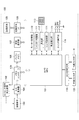
図1は、本発明の実施例1に係る発光装置としての外部ストロボ120が装着され、且つ同発光装置としての内蔵ストロボ119と一体となったデジタルカメラ(以下、単にカメラと称す)100の構成を示すブロック図である。
Example 1
(Basic camera configuration)
FIG. 1 shows a configuration of a digital camera (hereinafter simply referred to as a camera) 100 in which an
なお、図1に示すカメラ100の構成要素の1つ以上は、ASICやプログラマブルロジックアレイ(PLA)などのハードウェアによって実現されてもよい。また、CPUやMPU等のプログラマブルプロセッサがソフトウェアを実行することによって実現されてもよい。
Note that one or more of the components of the
また、ソフトウェアとハードウェアの組み合わせによって実現されてもよい。 Further, it may be realized by a combination of software and hardware.
したがって、以下の説明において、異なる構成要素が動作主体として記載されている場合であっても、同じハードウェアが主体として実現されうる。 Therefore, in the following description, even if different components are described as the operation subject, the same hardware can be realized as the subject.
カメラ100は、MPU101、撮像素子103、タイミング信号発生回路102、A/D変換器104、メモリコントローラ105、バッファメモリ106、画像表示部107、インターフェース108、及び記録媒体109を備える。
The
MPU101は、撮影シーケンスなどシステムを制御するためのカメラ100のマイクロコントローラである。撮像素子103は、被写体からの反射光を電気信号に変換するCCDやCMOS等により構成される。タイミング信号発生回路102は、撮像素子103を動作させるために必要なタイミング信号を発生する。
The MPU 101 is a microcontroller of the
A/D変換器104は、撮像素子103から読み出されたアナログ画像データをデジタル画像データに変換する。メモリコントローラ105は、バッファメモリ106に対するデータの読み書きやバッファメモリ106のリフレッシュ動作などを制御する。
The A /
画像表示部107は、バッファメモリ106に蓄えられた画像データを表示する。インターフェース108は、記録媒体109をカメラ100に接続するためのインターフェースである。記録媒体109は、メモリカードやハードディスクなどから構成される。
The
カメラ100は、さらにモーター制御部110、シャッター制御部111、測光部112、多分割測光センサ113、レンズ制御部114、焦点検出部115、スイッチ操作部116、及びストロボ制御部118を備える。
The
モーター制御部110は、露出動作時にMPU101からの信号に従って不図示のモーターを制御することにより、不図示のミラーのアップ・ダウンやシャッターのチャージを行う。
The
シャッター制御部111は、MPU101からの信号に従って、不図示のシャッターを制御して、撮像素子103の露出動作を制御する。
The
測光部112は、センサ領域を複数のエリアに分割し、各エリアで輝度を測光する多分割測光センサ113からの出力を、撮影の露出調節時において、輝度信号としてMPU101に出力する。MPU101は、この輝度信号をA/D変換器104により変換を行う。またこの変換結果に基づき、撮影の露出調節のための不図示の絞りの値Av(絞り値)や、シャッター制御部111で用いられる制御値Tv(シャッタースピード)、ISO(撮像素子103の感度)等の測光演算を行う。
The
また測光部112は同様に、外部ストロボ120、または内蔵ストロボ119にて被写体へ向けて予備(プリ)発光した時の輝度信号をMPU101に出力する。MPU101は、この輝度信号を変換することにより、実際に外部ストロボ120、または内蔵ストロボ119を用いてストロボ撮影するときのストロボ発光量(以下「メイン発光量」という。)の演算も行う。
Similarly, the
なお、MPU101は、多分割測光センサ113の出力でなく、撮像素子103で撮像した画像データを使って、上記測光演算やメイン発光量の演算を行うようにしてもよい。
Note that the
レンズ制御部114は、不図示のレンズマウント接点を介してMPU101と通信し、不図示のレンズ駆動モーター及びレンズ絞りモーターを動作させ、不図示のレンズの焦点調節と絞りを制御している。
The
焦点検出部115は、AF(オートフォーカス)のための被写体に対するデフォーカス量を検出する。
The
スイッチ操作部116は、不図示のレリーズスイッチ、電源スイッチ、その他のスイッチにより構成される。スイッチ操作部116は、これらのスイッチに対するユーザ操作を検知すると、その検知結果に応じて、スイッチ操作部116と接続するSW1、SW2、Power等のON/OFFを切り替える。また、スイッチ操作部116は、かかる検知が有った場合、SW1、SW2、Power等のON/OFFを示す検知信号をMPU101に送信する。ここで、SW1(撮影準備スイッチ)は、スイッチ操作部116がレリーズボタンへのユーザによる第1ストローク(半押し)を検知したときにONに切り替えられる。また、MPU101はSW1のONを示す検知信号がスイッチ操作部116から送信された場合、撮影準備に入る。具体的には、AF(測距)および測光を開始させる。また、SW2は、スイッチ操作部116がレリーズボタンへのユーザによる第2ストローク(全押し)を検知したときにONに切り替えられる。また、MPU101はSW2のONを示す検知信号がスイッチ操作部116から送信された場合、撮影を行う。具体的には、露出動作を開始させる。Powerは、スイッチ操作部116が電源スイッチをユーザがOFFからONに切り替えたことを検知したときにONに切り替わる。MPU101にはPowerのONを示す検知信号がスイッチ操作部116から送信されると共に電源が供給される。MPU101は、その後、スイッチ操作部116が備える、レリーズスイッチその他スイッチに対するユーザ操作を待ってこれに応じた制御を行う、撮影指示待機状態となる。
The
スイッチ操作部116において、SW1、SW2及びその他スイッチが、ON又はOFFに切り替わると、その旨を示す信号がスイッチ操作部116からMPU101に送信される。
In the
ストロボ制御部118は、発光パターン(プリ発光指示orメイン発光指示)や、メイン発光量等の発光処理や、内蔵ストロボ119と外部ストロボ120のどちらを使用するかの切り替え制御を行う。
The
また、内蔵ストロボ119及び外部ストロボ120との通信はストロボ制御部118を介して行う。
Further, communication with the built-in strobe 119 and the
尚、本実施例では、外部ストロボ120がカメラ100に装着されるだけでなく、内蔵ストロボ119がカメラ100に内蔵されているが、ストロボ撮影に使用する少なくとも一方のみがカメラ100と通信できる状態であればよい。
In the present embodiment, not only the
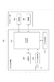
次に、外部ストロボ120の構成について図2で説明する。
Next, the configuration of the
外部ストロボ120は、ストロボ本体部とストロボヘッド部により構成される。ストロボ本体部には、マイクロコントローラ(以下「S−MPU」という。)201、表示部208、スイッチ操作部209、及びカメラ接続部210を備える。また、ストロボヘッド部には、充電部202及び発光部203を備える。
The
S−MPU201は、電源シーケンス、充電シーケンス、発光制御シーケンスなど外部ストロボ120を機能させるためのシステムを制御する。
The S-
充電部202は、不図示の昇圧回路によって充電されるメインコンデンサを備えており、メインコン電圧(以下、「充電電圧」という。)をS−MPU201に出力する。また、S−MPU201からの指示に応じて、メインコンデンサに充電した電荷を、ストロボ光を発光させるべく発光部203に流れ込ませる。
The charging
S−MPU201はこの充電電圧を不図示のA/D変換器により変換を行い、充電電圧が、単にストロボ光の発光が保証するレベル(以下「発光可能レベル」という。:第2のレベル)か、発光可能レベルより高い、ストロボ光の最大発光が可能なレベル(以下「フル充電レベル」という。:第1のレベル)かの判断などの演算を行う。この演算結果、及び図4で後述する充電制御により、メインコンデンサに充電した電荷を発光部203に流れ込ませる指示を充電部202に行う。ここで、本実施例においては、フル充電レベルとは、充電部202のメインコンデンサの耐圧電圧近傍を指す。
The S-
発光部203は、S−MPU201からの発光信号に従って、ストロボ光を発光する不図示のストロボ発光回路を備えている。
The
表示部208は、充電部202における充電の完了/未完了表示などを行う。具体的には、S−MPU201により充電電圧が発光可能レベルやフル充電レベルであると判断されると、不図示のLEDランプを点灯することによって、使用者にストロボ光が発光可能であることを通知する。
The
スイッチ操作部209は、不図示の1以上のボタン/スイッチにより構成され、これらのスイッチに対するユーザ操作を検知すると、その検知結果に応じて、スイッチ操作部209と接続するPower等のON/OFFを切り替える。また、スイッチ操作部209は、かかる検知があった場合、Power等のON/OFFを示す検知信号をS−MPU201に送信する。また、PowerがONとなった場合、S−MPU201に電源が供給される。
The
カメラ接続部210は、カメラ100に外部ストロボ120を装着するための接続部であり、且つ、カメラ100への装着中においては、S−MPU201がカメラ100のMPU101と通信するための通信部である。
The
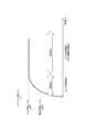
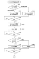
ここで、従来より一般的なストロボの充電制御(以下「第一充電制御」という。)について図3を使って説明する。 Here, conventional charge control of a strobe (hereinafter referred to as “first charge control”) will be described with reference to FIG.
MPU101はスイッチ操作部116からSW1のONを示す検知信号が送信されると、外部ストロボ120に対して、第一充電制御の指示を行う。
When the
この指示を受けたS−MPU201は、図3の期間3Aに示すように、充電電圧がフル充電レベルより低い場合、フル充電レベルになるまで充電部202を充電した後、図3の期間3Bに示すように、その充電電圧を維持し続ける制御を行う。
When the charging voltage is lower than the full charge level, the S-
本実施例では、S−MPU201は、充電部202に対する充電制御を、図4に示すように、第一充電制御及び第二充電制御を切り替えて行う(切替手段)。すなわち、SW1がONとなった場合、S−MPU201は、期間4Cに示すように、いつでもストロボ撮影ができ、且つ、発光性能を最大に引き出せるように前述した第一充電制御を行う。一方、カメラ100が撮影指示待機状態の場合、S−MPU201は、ストロボ発光に必要最低限の電圧が維持できるようにした第二充電制御を行う。具体的には、まず、期間4Aに示すように、充電電圧がフル充電レベルになるまで充電部202を充電した後、期間4Bに示すように、自然放電で充電電圧が発光可能レベルとなったときに、再度、フル充電レベルまで充電する。
In the present embodiment, the S-
図3や図4の期間3Aや期間4Aは、外部ストロボ120の充電部202が空の状態でS−MPU201によって初めて充電される場合の充電制御を表している。この場合は、第一充電制御、第二充電制御のどちらにおいても充電電圧がフル充電レベルになるまで充電部202の充電が行われる。
Periods 3A and 4A in FIG. 3 and FIG. 4 represent charging control when the charging
尚、充電部202のメインコンデンサの耐圧電圧近傍となるフル充電レベルを第一充電制御及び第二充電制御における目標とするレベルとしたがこれに限定されない。すなわち、発光可能レベルより高いレベルであり、ストロボ発光が最大となるレベルであれば、フル充電レベルより低いレベルを目標とするレベルとしてもよい。
Although the full charge level in the vicinity of the withstand voltage of the main capacitor of the charging
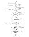
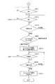
次に、第二充電制御を行う本実施例の充電制御処理について、図5A,5Bのフローチャートを用いて説明をする。 Next, the charge control process of the present embodiment for performing the second charge control will be described using the flowcharts of FIGS. 5A and 5B.
本処理は、カメラ100がスイッチ操作部116の電源スイッチの切り替えでPowerがオンされた後、ストロボ撮影モードに設定された状態で開始する。また、カメラ100には外部ストロボ120が装着されている。
This process starts when the
まず、ステップS501で、MPU101は、カメラ100が撮影待機状態であると判断し、ストロボ制御部118を介して、第二充電制御の指示を外部ストロボ120に行う。この指示に応じて、S−MPU201は、充電部202に対する第二充電制御を開始する。尚、ステップS501の第二充電制御の指示は、外部ストロボ120とMPU101との間での通信が可能となったと判定できるタイミングであれば、上記タイミングに限定されない。例えば、外部ストロボ120とMPU101とが通信可能な状態である場合にユーザがストロボ撮影モードをカメラ100においてONに切り替えた場合にステップS501の指示が行われるようにしてもよい。
First, in step S <b> 501, the
ステップS502では、ユーザによりレリーズスイッチが半押しされ、SW1がONとなるのを待ち、ONとなると、撮影準備に入ると共にステップS503に進み、MPU101は外部ストロボ120に第一充電制御の指示を行う。この指示に応じて、S−MPU201は、ステップS501の指示に応じて開始した充電部202に対する第二充電制御を第一充電制御に切り替える。
In step S502, the user waits for the release switch to be pressed halfway and SW1 to be turned on. When the switch is turned on, shooting preparation is started and the process proceeds to step S503, where the
ステップS504で、カメラ100は測光・測距を行い、ステップS505で、ユーザによりレリーズスイッチが全押しされ、SW2がONとなるのを待つ。SW2がONとなると、ステップS506に進む。
In step S504, the
ステップS506では、ステップS504の測光・測距結果に基づいて、外部ストロボ120を発光させたストロボ撮影を行うステップS507に進むか、外部ストロボ120を発光させないAE撮影を行うステップS509に進むかを判定する。
In step S506, based on the photometry / distance measurement result in step S504, it is determined whether the process proceeds to step S507 in which strobe shooting is performed with the
ステップS507でストロボ撮影した後は、ステップS508で外部ストロボ120にフル充電レベルまで再充電する指示を行い、ステップS510に進む。尚、図3に示す第一充電制御を実行するためのプログラムに基づきS−MPU201が動作しているため、この再充電の指示はなくても、外部ストロボ120においてフル充電レベルまでの再充電が行われる。一方、ステップS509でAE撮影した後は直接ステップS510に進む。
After the flash photography in step S507, the
その後、ステップS510,S511でSW2とSW1がそれぞれOFFとなると、ステップS512,S513では、再度ユーザによりレリーズスイッチが半押しされ、所定時間経過までにSW1がONとなるのを待つ。所定時間経過までに再度SW1がONとなった場合は(ステップS513で未経過、ステップS512でON)ステップS503に戻る。一方、再度SW1がONとなることなく所定時間が経過した場合は(ステップS512でOFF、ステップS513で経過)、撮影指示待機状態であると判断して、ステップS514に進む。 Thereafter, when SW2 and SW1 are turned off in steps S510 and S511, respectively, in steps S512 and S513, the release switch is half-pressed again by the user and waits for SW1 to be turned on until a predetermined time elapses. If SW1 is turned on again by the predetermined time (not passed in step S513, turned on in step S512), the process returns to step S503. On the other hand, if the predetermined time has elapsed without turning SW1 ON again (OFF in step S512, elapses in step S513), it is determined that the camera is in the shooting instruction standby state, and the process proceeds to step S514.
ステップS514では外部ストロボ120に第二充電制御の指示を行う。この指示に応じて、S−MPU201は、ステップS503の指示に応じて開始した充電部202に対する第一充電制御を第二充電制御に切り替える。
In step S514, the
その後、ステップS515,S516で更に所定時間経過までにレリーズスイッチ及び電源スイッチ以外のスイッチ操作部116が備える他のスイッチが操作された場合はステップS503に戻る。一方、他のスイッチが操作されることなく所定時間経過した場合、ステップS517に進む。
Thereafter, in step S515, S516, if another switch provided in the
ステップS517では外部ストロボ120に充電停止の指示を行って、本処理を終了する。
In step S517, the
なお、本実施例では、外部ストロボ120への充電制御処理について説明したが、内蔵ストロボ119への充電制御処理であっても良い。以下、本実施例の充電制御処理の対象を単にストロボという。
In the present embodiment, the charging control process for the
以上、図5A.5Bに示す本実施例における、ストロボへの充電制御処理によれば、カメラ100のMPU101からの指示に応じて、ストロボのS−MPU201が充電部202に対する充電制御を、第一充電制御及び第二充電制御の一方に切り替える。ここで、MPU101からの指示とは、カメラ100が撮影指示待機状態であると判断された場合においては(ステップS501,S514)、第二充電制御の指示である。また、SW1がONとなり、カメラ100が撮影準備に入った場合においては(ステップS503)、第一充電制御の指示である。これにより、撮影指示待機状態においてはS−MPU201は第二充電制御を行うため、ストロボ充電による電池の消耗を軽減できる。また、SW1がONとなった場合にはS−MPU201は第一充電制御を行うため、撮影タイミングの逸失を無くすことができる。
As described above, FIG. According to the charge control processing for the strobe in this embodiment shown in FIG. 5B, the S-
さらに、本発明ではフル充電レベルを、充電部202の耐圧電圧近傍に設定したが、ストロボ発光の発光性能を最大に引き出せる電圧であれば、フル充電レベルを耐圧電圧近傍よりも所定量低い電圧に設定しても良い。
Further, in the present invention, the full charge level is set in the vicinity of the withstand voltage of the charging
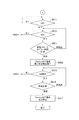
また、ストロボは、自動発光設定及び強制発光設定を含む複数の発光モードの1つに設定できるようにしてもよい(設定手段)。ここで、自動発光設定とは、ストロボの発光モードの設定が測光結果に応じて撮影時における発光/非発光を切り替える発光モードの設定を指す。また、強制発光設定とは、撮影時には必ず発光を行う発光モードの設定を指す。この場合、以下、図6A,6Bに示す、図5A,5Bの充電制御処理の変形例のように、ストロボが強制発光設定では、常に第一充電制御だけを行い、自動発光設定の時に第一充電制御と第二充電制御を切り替える。 The strobe may be set to one of a plurality of light emission modes including an automatic light emission setting and a forced light emission setting (setting unit). Here, the automatic flash setting refers to a flash mode setting in which the flash mode setting switches between flashing / non-flashing during shooting according to the photometric result. The forced light emission setting is a setting of a light emission mode in which light emission is always performed at the time of shooting. In this case, as shown in FIGS. 6A and 6B, the first charge control is always performed when the strobe is set to the forced flash setting, as in the modification of the charge control process of FIGS. 5A and 5B. Switching between charge control and second charge control.
図6A,6Bのフローチャートのうち、ステップS601〜S603のみが図5A,5Bのフローチャートと異なるので、以下ステップS601〜S603について説明する。それ以外のステップについては、図5A,5Bのフローチャートと同一であるので、同一のステップには同一のステップ番号を付し重複した説明は省略する。 6A and 6B, only steps S601 to S603 are different from the flowcharts of FIGS. 5A and 5B, so steps S601 to S603 will be described below. Since the other steps are the same as those in the flowcharts of FIGS. 5A and 5B, the same steps are denoted by the same step numbers and redundant description is omitted.
まず、MPU101は、本処理開始時においてカメラ100が撮影待機状態であると判断すると、ステップS601で自動発光設定なのか、強制発光設定なのかをストロボに問合せる。この問合せに応じて、S−MPU201は、設定されている発光モード設定をカメラ100に通知する(通知手段)。尚、カメラ100においてストロボにおいて現在設定されている発光モードが認識できる方法であれば、かかる問合せによる方法に限定されない。例えば、ストロボにおいて発光モードの設定が変更されたときに、ストロボからカメラ100に発光モードの設定を通知するようにしてもよい。
First, when the
この問合せの結果、自動発光設定ならステップS501に進み、第二充電制御の指示をストロボに行う。一方、強制発光設定ならステップS602に進み、第一充電制御の指示をストロボに行う。この指示に応じた充電制御を、S−MPU201は、充電部202に対して開始する。
As a result of the inquiry, if automatic light emission is set, the process proceeds to step S501 to instruct the second charging control to the strobe. On the other hand, if the forced light emission is set, the process proceeds to step S602, and the first charging control instruction is given to the strobe. The S-
その後、ステップS502〜S509の処理を行なう。その後、ステップS510,S511でSW2とSW1がそれぞれOFFとなった後、ステップS512,S513で再度SW1がONとなることなく所定時間が経過した場合、撮影指示待機状態であると判断して、ステップS603に進む。 Thereafter, the processes of steps S502 to S509 are performed. Thereafter, after SW2 and SW1 are turned off in steps S510 and S511, if a predetermined time has passed without SW1 being turned on again in steps S512 and S513, it is determined that the camera is in a shooting instruction standby state. The process proceeds to S603.
ステップS603では、ストロボの発光モードの設定を判定し、自動発光設定であれば、ステップS514に進み、ストロボに第二充電制御の指示をストロボに行う。ステップS602の指示に応じて充電部202に対して第一充電制御を行っている場合は、ステップS603の指示に応じて、S−MPU201は、充電部202に対する第一充電制御を第二充電制御に切り替える。一方、強制発光設定であれば、ステップS515に進む。尚、本変形例では、ステップS515,S516で更に所定時間経過までにレリーズスイッチ及び電源スイッチ以外のスイッチ操作部116が備える他のスイッチが操作された場合はステップS501に戻る。
In step S603, the setting of the flash mode of the strobe is determined. If the automatic flash setting is set, the process proceeds to step S514, and the second charge control instruction is given to the strobe. When the first charging control is performed on the
以降の処理については、図5のフローチャートと同じであるため説明は割愛する。 Since the subsequent processing is the same as the flowchart of FIG.
以上、図6A,6Bに示す本実施例におけるストロボへの充電制御処理の変形例によれば、MPU101は、カメラ100が撮影指示待機状態であると判断した場合、ストロボの発光モードの設定を判定する(ステップS601,S603)。この判定の結果に応じて第一充電制御の指示及び第二充電制御の指示の一方を行う。具体的ンは、自動発光設定であれば第二充電制御の指示をストロボに行い、強制発光設定であれば第一充電制御の指示をストロボに行う。これにより、カメラ100が撮影指示待機状態であって且つストロボが強制発光設定である場合、S−MPU201は第二充電制御を行うため、ストロボ充電による電池の消耗を軽減することができる。その一方、カメラ100が撮影指示待機状態であってもストロボが自動発光設定である場合は、S−MPU201は第一充電制御を行うため、撮影タイミングの逸失を確実に無くすことができる。
As described above, according to the modification of the flash charging control process in the present embodiment shown in FIGS. 6A and 6B, when the
また、前述した実施形態では、本発明を実施する撮像装置の一例としてレンズ交換式で光学ファインダのあるデジタルカメラとしてのカメラ100について説明したが、これに限定されるものではない。
In the above-described embodiment, the
例えば、光学ファインダのないデジタルカメラやレンズ一体型のデジタルカメラ、デジタルビデオカメラやスマートフォンなどの可搬デバイスやウェアラブル端末、セキュリティーカメラなど、デジタルカメラ以外の撮像装置を採用する構成であってもよい。 For example, an imaging apparatus other than a digital camera, such as a digital camera without an optical finder, a lens-integrated digital camera, a portable device such as a digital video camera or a smartphone, a wearable terminal, or a security camera may be employed.
(実施例2)
本実施例は、実施例1の図4に示すフル充電レベルと発光可能レベルの間に、スリープ時の充電停止レベル(第3のレベル)を設け、スリープ時は、発光可能レベルまでは自然放電して、スリープ時の充電停止レベルまで上昇を繰り返す点が異なる。
(Example 2)
In the present embodiment, a charge stop level (third level) at the time of sleep is provided between the full charge level shown in FIG. 4 of the first embodiment and the light emission possible level. And the point which repeats a rise to the charge stop level at the time of sleep differs.
よって、本実施例と実施例1は、図1,2に示すカメラ100及び外部ストロボ120の構成は同一であるため、同一の構成要素については同一の符号を付し、重複した説明は省略する。
Therefore, since the configuration of the
まず、本実施例2に係るストロボの充電制御(第三充電制御)について図7を使って説明する。 MPU101はスイッチ操作部116からのSW1のONを示す検知信号が送信されると、外部ストロボ120へ充電指示を行う。
First, strobe charge control (third charge control) according to the second embodiment will be described with reference to FIG. When the
この指示を受けたS−MPU201は、図3の期間3Aに示すように、充電電圧がフル充電レベルになるまで充電部202を充電した後、図3の期間3Bに示すように、その充電電圧を維持し続ける第一充電制御を行う。
Upon receiving this instruction, the S-
その後、レリーズスイッチ及び電源スイッチ以外のスイッチ操作部116が備える他のスイッチなどへのユーザ操作が所定時間行われなかった場合、MPU101は省電力モードに入る。この際、MPU101は、画像表示部107を消灯して、外部ストロボ120へ省電力モード指示を行う。
Thereafter, when a user operation is not performed for a predetermined time on other switches provided in the
省電力モード指示を受けたS−MPU201は、図7の期間7Bに示すような、発光可能レベルを下回らないように間欠にスリープ時の充電停止レベルまでの充電を行う第三充電制御を行う。
Receiving the power saving mode instruction, the S-
第三充電制御の方法の一例を以下に示す。 An example of the third charge control method is shown below.
まず、不図示の放電カーブに基づいて、充電電圧がフル充電レベルから発光可能レベルまで下降する時間Tаを算出し、次回起動時間Taとして設定し、S−MPU201の動作を停止させて、外部ストロボ120をスリープ状態とする。
First, based on a discharge curve (not shown), the time T a when the charging voltage falls from the full charge level to the light emission possible level is calculated, set as the next activation time Ta, the operation of the S-
スリープ状態となってから時間Taが経過した後、S−MPU201は起動して、充電電圧がスリープ時の充電停止レベルになるまで充電部202を充電する。
After the time Ta has elapsed since entering the sleep state, the S-
次に不図示の放電カーブに基づいて、充電電圧がスリープ時の充電停止レベルから発光可能レベルまで下降する時間Tbを算出し、次回起動時間Tbとして設定し、S−MPU201の動作を停止させて、外部ストロボ120を再度スリープ状態とする。再度のスリープ状態となってから時間Tbが経過した後、S−MPU201は起動して、スリープ状態となってから時間Taが経過した後以降に行った処理と同じ処理を以下の条件が発生するまで繰り返す。繰り返し処理を停止させる条件を以下に示す。
Next, based on a discharge curve (not shown), a time Tb in which the charging voltage falls from the charge stop level at the time of sleep to the light emission possible level is calculated, set as the next start time Tb, and the operation of the S-
1.MPU101からS−MPU201に指示があった場合
2.時間Tb後のS−MPU201の起動回数(充電部202への再充電回数)が所定回数以上となった場合
3.カメラ100から外部ストロボ120が取り外された場合
4.S−MPU201のスイッチ操作部209の電源スイッチがユーザによりOFFに切り替えられ、S−MPU201の電源供給が停止された場合
2〜4の条件を満たす場合は、充電停止制御を行い、S−MPU201の動作を停止させて、外部ストロボ120をスリープ状態とする。
1. When there is an instruction from the
1の条件を満たす場合は、S−MPU201は、その指示に応じた充電制御を行う。例えば、MPU101から第一充電制御の指示があった場合は、期間7Cに示すような、充電電圧がフル充電レベルになるまで充電部202を充電した後、その充電電圧を維持し続ける制御を行う。
When the condition 1 is satisfied, the S-
次に、この充電制御を行う本実施例の充電制御処理について、図8A,8Bのフローチャートを用いて説明をする。 Next, the charge control process of the present embodiment for performing this charge control will be described with reference to the flowcharts of FIGS. 8A and 8B.
本処理において、図5A,5Bのフローチャートで示す実施例1の充電制御処理と同一のステップについては、同一のステップ番号を付し、重複した説明は省略する。尚、本処理は、実施例1と異なり、ステップS501は実行せず、ステップS502から実行を開始する。 In this process, the same steps as those in the charge control process of the first embodiment shown in the flowcharts of FIGS. 5A and 5B are denoted by the same step numbers, and redundant description is omitted. Note that, unlike the first embodiment, this process does not execute step S501 and starts execution from step S502.
まず、ステップS502〜S509まで、実施例1の充電制御処理と同一の処理を行なう。その後、ステップS510,S511でSW2とSW1がそれぞれOFFとなった後、再度SW1がONとなることなく省電力モードタイマ時間が経過すると(ステップS512でOFF、ステップS801で経過)、ステップS802に進む。 First, from step S502 to S509, the same process as the charge control process of the first embodiment is performed. Thereafter, after SW2 and SW1 are turned off in steps S510 and S511, if the power saving mode timer time elapses without turning SW1 on again (OFF in step S512, elapses in step S801), the process proceeds to step S802. .
ステップS802では、画像表示部107を消灯してカメラ100を省電力モードに移行すると共に、外部ストロボ120に第三充電制御の指示を行う。
In step S <b> 802, the
以降の処理については、図5のフローチャートと同じであるため説明は割愛する。 Since the subsequent processing is the same as the flowchart of FIG.
以上、図8A,8Bに示す本実施例におけるストロボへの充電制御処理によれば、MPU101は、カメラ100を省電力モードに移行した場合(ステップS801)、外部ストロボ120に三充電制御の指示を行う(ステップS802)。これにより、カメラ100が省電力モードである場合においては、S−MPU201は第三充電制御を行うため、ストロボ充電による電池の消耗を確実に軽減することができる。
As described above, according to the strobe charging control process in the present embodiment shown in FIGS. 8A and 8B, when the
(その他の実施形態)
また本発明は、上述の実施形態の1以上の機能を実現するプログラムを、ネットワーク又は記憶媒体を介してシステム又は装置に供給し、そのシステム又は装置のコンピュータにおける1つ以上のプロセッサーがプログラムを読出し実行する処理でも実現できる。また、1以上の機能を実現する回路(例えば、ASIC)によっても実現できる。
(Other embodiments)
In addition, the present invention supplies a program that realizes one or more functions of the above-described embodiment to a system or apparatus via a network or a storage medium, and one or more processors in a computer of the system or apparatus read the program. It can also be realized by executing processing. It can also be realized by a circuit (for example, ASIC) that realizes one or more functions.
(その他の実施例)
本発明の目的は、前述した実施形態の機能を実現するソフトウェアのプログラムコードを記録した記憶媒体を、装置に供給することによっても、達成されることは言うまでもない。このとき、供給された装置の制御部を含むコンピュータ(またはCPUやMPU)は、記憶媒体に格納されたプログラムコードを読み出し実行する。
(Other examples)
It goes without saying that the object of the present invention can also be achieved by supplying a storage medium storing software program codes for realizing the functions of the above-described embodiments to the apparatus. At this time, the computer (or CPU or MPU) including the control unit of the supplied apparatus reads and executes the program code stored in the storage medium.
この場合、記憶媒体から読み出されたプログラムコード自体が前述した実施形態の機能を実現することになり、プログラムコード自体及びそのプログラムコードを記憶した記憶媒体は本発明を構成することになる。 In this case, the program code itself read from the storage medium realizes the functions of the above-described embodiments, and the program code itself and the storage medium storing the program code constitute the present invention.
プログラムコードを供給するための記憶媒体としては、例えば、フレキシブルディスク、ハードディスク、光ディスク、光磁気ディスク、CD−ROM、CD−R、磁気テープ、不揮発性のメモリカード、ROM等を用いることができる。 As a storage medium for supplying the program code, for example, a flexible disk, a hard disk, an optical disk, a magneto-optical disk, a CD-ROM, a CD-R, a magnetic tape, a nonvolatile memory card, a ROM, or the like can be used.
また、上述のプログラムコードの指示に基づき、装置上で稼動しているOS(基本システムやオペレーティングシステム)などが処理の一部又は全部を行い、その処理によって前述した実施形態の機能が実現される場合も含まれることは言うまでもない。 Further, the OS (basic system or operating system) running on the apparatus performs part or all of the processing based on the instruction of the program code described above, and the functions of the above-described embodiments are realized by the processing. Needless to say, cases are also included.
さらに、記憶媒体から読み出されたプログラムコードが、装置に挿入された機能拡張ボードやコンピュータに接続された機能拡張ユニットに備わるメモリに書込まれ、前述した実施形態の機能が実現される場合も含まれることは言うまでもない。このとき、そのプログラムコードの指示に基づき、その機能拡張ボードや機能拡張ユニットに備わるCPU等が実際の処理の一部又は全部を行う。 Further, the program code read from the storage medium may be written into a memory provided in a function expansion board inserted into the apparatus or a function expansion unit connected to the computer, and the functions of the above-described embodiments may be realized. Needless to say, it is included. At this time, based on the instruction of the program code, the CPU or the like provided in the function expansion board or function expansion unit performs part or all of the actual processing.
100 カメラ
101 MPU
103 撮像素子
116 スイッチ操作部
118 ストロボ制御部
119 内蔵ストロボ
120 外部ストロボ
201 S−MPU
202 充電部
203 発光部
210 カメラ接続部
100
103
202
Claims (10)
前記充電部の充電電圧が目標とする第1のレベルより低い場合、前記充電電圧が前記第1のレベルになるまで前記充電部を充電する第一充電制御を行う第一充電制御手段、及び、前記充電電圧が前記第1のレベルより低い第2のレベルとなったときに前記充電電圧が前記第1のレベルになるまで前記充電部を充電する第二充電制御を行う第二充電制御手段を含む複数の充電制御手段と、
前記撮像装置からの指示に応じて、前記複数の充電制御手段の1つに切り替える切替手段とを備えることを特徴とする発光装置。 A light emitting device including a communication unit that communicates with a control unit of an imaging device, a light emitting unit, and a charging unit that charges a charge for causing the light emitting unit to emit light,
First charging control means for performing first charging control for charging the charging unit until the charging voltage reaches the first level when the charging voltage of the charging unit is lower than a target first level; and Second charge control means for performing second charge control for charging the charging unit until the charge voltage becomes the first level when the charge voltage becomes a second level lower than the first level; Including a plurality of charging control means,
A light emitting device comprising: switching means for switching to one of the plurality of charge control means in response to an instruction from the imaging device.
前記撮像装置が撮影待機状態であると前記撮像装置において判断された場合、前記通知手段により通知された発光モードの設定に応じて、前記第一充電制御を行う指示及び前記第二充電制御を行う指示の一方が前記指示として行われることを特徴とする請求項1乃至3のいずれか1項に記載の発光装置。 A setting means for setting to one of a plurality of light emission modes, and a notification means for notifying the imaging apparatus of the setting of the light emission mode by the setting means,
When the imaging apparatus determines that the imaging apparatus is in a shooting standby state, the instruction to perform the first charging control and the second charging control are performed according to the setting of the light emission mode notified by the notification unit. 4. The light emitting device according to claim 1, wherein one of the instructions is given as the instruction.
前記撮像装置が省電力モードに移行したと前記撮像装置において判断された場合、前記指示として前記第三充電制御を行う指示が行われることを特徴とする請求項1乃至6のいずれか1項に記載の発光装置。 When the charging voltage reaches the second level, third charging control is performed to charge the charging unit until the charging voltage reaches a third level between the first and second levels. Further comprising three charge control means,
The instruction to perform the third charging control is performed as the instruction when the imaging apparatus determines that the imaging apparatus has shifted to the power saving mode. The light-emitting device of description.
前記充電部の充電電圧が目標とする第1のレベルより低い場合、前記充電電圧が前記第1のレベルになるまで前記充電部を充電する第一充電制御を行う第一充電制御ステップ、及び、前記充電電圧が前記第1のレベルより低い第2のレベルとなったときに前記充電電圧が前記第1のレベルになるまで前記充電部を充電する第二充電制御を行う第二充電制御ステップを含む複数の充電制御ステップと、
前記撮像装置からの指示に応じて、前記複数の充電制御ステップの1つに切り替える切替ステップとを有することを特徴とする充電制御方法。 A charge control method for a light emitting device including a communication unit that communicates with a control unit of an imaging device, a light emitting unit, and a charging unit that charges a charge for causing the light emitting unit to emit light,
A first charging control step of performing a first charging control for charging the charging unit until the charging voltage reaches the first level when the charging voltage of the charging unit is lower than a target first level; and A second charge control step of performing a second charge control for charging the charging unit until the charge voltage becomes the first level when the charge voltage becomes a second level lower than the first level; A plurality of charge control steps including:
And a switching step of switching to one of the plurality of charging control steps in response to an instruction from the imaging device.
Priority Applications (2)
| Application Number | Priority Date | Filing Date | Title |
|---|---|---|---|
| JP2018072585A JP2019184703A (en) | 2018-04-04 | 2018-04-04 | Light-emitting device, and charge control method and program thereof |
| US16/369,486 US20190313004A1 (en) | 2018-04-04 | 2019-03-29 | Light-emitting apparatus for shooting with flash, charging control method therefor, and storage medium |
Applications Claiming Priority (1)
| Application Number | Priority Date | Filing Date | Title |
|---|---|---|---|
| JP2018072585A JP2019184703A (en) | 2018-04-04 | 2018-04-04 | Light-emitting device, and charge control method and program thereof |
Publications (1)
| Publication Number | Publication Date |
|---|---|
| JP2019184703A true JP2019184703A (en) | 2019-10-24 |
Family
ID=68097561
Family Applications (1)
| Application Number | Title | Priority Date | Filing Date |
|---|---|---|---|
| JP2018072585A Pending JP2019184703A (en) | 2018-04-04 | 2018-04-04 | Light-emitting device, and charge control method and program thereof |
Country Status (2)
| Country | Link |
|---|---|
| US (1) | US20190313004A1 (en) |
| JP (1) | JP2019184703A (en) |
Families Citing this family (1)
| Publication number | Priority date | Publication date | Assignee | Title |
|---|---|---|---|---|
| CN113347367B (en) * | 2020-03-02 | 2022-07-19 | 浙江宇视科技有限公司 | Light supplement lamp, control method and device thereof, electronic equipment, medium and shooting system |
Family Cites Families (4)
| Publication number | Priority date | Publication date | Assignee | Title |
|---|---|---|---|---|
| JP2002344794A (en) * | 2001-05-18 | 2002-11-29 | Fuji Photo Film Co Ltd | Digital camera |
| JP3837739B2 (en) * | 2001-06-29 | 2006-10-25 | フジノン株式会社 | camera |
| JP6305091B2 (en) * | 2014-02-13 | 2018-04-04 | キヤノン株式会社 | LIGHT EMITTING DEVICE, ITS CONTROL METHOD, CONTROL PROGRAM, AND IMAGING DEVICE |
| JP6425413B2 (en) * | 2014-04-28 | 2018-11-21 | キヤノン株式会社 | Imaging device, control method, and program |
-
2018
- 2018-04-04 JP JP2018072585A patent/JP2019184703A/en active Pending
-
2019
- 2019-03-29 US US16/369,486 patent/US20190313004A1/en not_active Abandoned
Also Published As
| Publication number | Publication date |
|---|---|
| US20190313004A1 (en) | 2019-10-10 |
Similar Documents
| Publication | Publication Date | Title |
|---|---|---|
| EP1499111B1 (en) | Image sensiting apparatus, image processing apparatus, and control method thereof | |
| US8614766B1 (en) | Systems and methods for controlling a power state of a remote device using camera body backlighting control signaling | |
| US10511770B2 (en) | Accessory apparatus and recording medium storing control program for accessory apparatus | |
| US20120099847A1 (en) | Systems and Methods For Controlling A Photographic Modeling Light Using One or More Camera Body Control Signals | |
| US20170019597A1 (en) | Light-emission control apparatus and method for the same | |
| JP2008151975A (en) | Imaging device and program thereof | |
| JP6425413B2 (en) | Imaging device, control method, and program | |
| JP2019184703A (en) | Light-emitting device, and charge control method and program thereof | |
| US11310437B2 (en) | Control apparatus, control method, image capturing apparatus, and storage medium | |
| JP2023069272A (en) | Light emitting device, its control method and program | |
| JP4603836B2 (en) | Imaging apparatus, control method therefor, program, and recording medium | |
| US8467673B2 (en) | Imaging apparatus, camera system, and illumination apparatus | |
| JP7140565B2 (en) | IMAGING DEVICE, IMAGING SYSTEM, CONTROL METHOD, AND PROGRAM | |
| US8447180B2 (en) | Imaging apparatus | |
| JP5392206B2 (en) | Camera and camera system | |
| JP2005249960A (en) | Imaging device and method of using auxiliary light in imaging device | |
| JP5423747B2 (en) | Accessories, camera, accessory control program, and camera control program | |
| JP4586211B2 (en) | Imaging device | |
| JP6232690B2 (en) | Imaging apparatus, illumination control method, and program | |
| JP6452310B2 (en) | Imaging apparatus, control method, and program | |
| JP2024013937A (en) | Light emission control device, imaging system, control method and program for light emission device | |
| JP2006343646A (en) | Imaging device and flash device | |
| JP3799104B2 (en) | camera | |
| JP2008270987A (en) | Imaging apparatus and control method thereof | |
| JP4235882B2 (en) | Still camera and still camera control method |