JP2019060126A - building - Google Patents
building Download PDFInfo
- Publication number
- JP2019060126A JP2019060126A JP2017185264A JP2017185264A JP2019060126A JP 2019060126 A JP2019060126 A JP 2019060126A JP 2017185264 A JP2017185264 A JP 2017185264A JP 2017185264 A JP2017185264 A JP 2017185264A JP 2019060126 A JP2019060126 A JP 2019060126A
- Authority
- JP
- Japan
- Prior art keywords
- wall
- space
- hole
- vent
- building
- Prior art date
- Legal status (The legal status is an assumption and is not a legal conclusion. Google has not performed a legal analysis and makes no representation as to the accuracy of the status listed.)
- Granted
Links
Images


Landscapes
- Building Environments (AREA)
Abstract
【課題】被換気空間を換気するために外壁及び梁の各々に孔が設けられた建物において、外壁部及び梁の間で各孔の周辺に設置される部材同士の干渉を抑制する。【解決手段】階間に被換気空間を有する建物において、建物の外縁部に設けられた外壁部と、外壁部と並ぶように設けられた鉄骨梁と、被換気空間の換気を行うために外壁部に形成された通気孔と、鉄骨梁に形成されており被換気空間を換気する際の空気の通路において通気孔よりも被換気空間に近い位置に設けられた貫通孔と、外壁部と鉄骨梁との間で通気孔の屋内側の開口を囲むように設けられた囲い壁と、貫通孔に挿通されており一部分が貫通孔の屋外側の開口から突出しているスリーブと、が備えられ、外壁部と鉄骨梁が並ぶ方向と交差する方向において、通気孔及び貫通孔が異なる位置にある。【選択図】図7PROBLEM TO BE SOLVED: To suppress interference between members installed around each hole between an outer wall portion and a beam in a building in which a hole is provided in each of an outer wall and a beam for ventilating a ventilated space. SOLUTION: In a building having a ventilated space between floors, an outer wall portion provided on an outer edge portion of the building, a steel beam provided alongside the outer wall portion, and an outer wall for ventilating the ventilated space. Ventilation holes formed in the part, through holes formed in the steel beam and provided closer to the ventilated space than the ventilation holes in the air passage when ventilating the ventilated space, the outer wall part and the steel frame. It is provided with an enclosure wall provided between the beam and the vent to surround the indoor opening of the vent, and a sleeve that is inserted through the through hole and partly protrudes from the outdoor opening of the through hole. Ventilation holes and through holes are located at different positions in the direction in which the outer wall portion and the steel beam are lined up and intersect. [Selection diagram] FIG. 7
Description
本発明は、建物に係り、特に、被換気空間を有し、当該被換気空間を換気することが可能な建物に関する。 The present invention relates to a building, and more particularly to a building having a ventilated space and capable of ventilating the ventilated space.
建物の中には、屋根下及び階間等に被換気空間を有するものが存在する。その一例としては、特許文献1に記載の建物が挙げられる。特許文献1に記載の建物は、外壁材の上端を陸屋根の極力近付けつつ、屋根下空間の換気を確実に行うことが可能な構造を採用している。
Some buildings have a ventilated space under the roof and between floors. The building of
また、特許文献1に記載の建物では、外壁に通気孔を設けると共に、屋根材を支える梁に貫通孔を設けている。かかる構成において、建物の外側の空気が外壁の通気孔を通過した後に梁の貫通孔を通って屋根下空間内に入り込むことで、屋根下空間の換気が行われる。
Moreover, in the building described in
ところで、上記のように外壁及び梁の各々に換気用の孔(具体的には、通気孔及び貫通孔)が設けられている構成において、外壁及び梁の間のスペース内で各孔周辺に部品が設置される場合がある。例えば、外壁に設けられた通気孔の周辺(厳密には、通気孔の屋内側の開口周辺)には、雨水の屋内への入り込みを防ぐための部材が設けられる場合がある。また、梁に設けられた貫通孔には、筒状の部材が挿通される場合がある。
以上のように外壁及び梁の間のスペースにおいて各孔の辺に部品を設置する場合には、部品同士の干渉を避けながら適切に各部品を設置する必要がある。
By the way, in the configuration in which the ventilating holes (specifically, the vent holes and the through holes) are provided in each of the outer wall and the beam as described above, parts around each hole in the space between the outer wall and the beam May be installed. For example, around the vent provided in the outer wall (strictly, around the opening on the indoor side of the vent), a member may be provided to prevent rainwater from entering the indoor. Moreover, a cylindrical member may be penetrated by the through-hole provided in the beam.
As described above, in the case of installing components on the side of each hole in the space between the outer wall and the beam, it is necessary to properly install each component while avoiding interference between the components.
また、梁周りの耐火性能を確保するため、外壁及び梁の間のスペースに耐火材を設置することがある。かかる構成において、耐火材の位置がずれたり、耐火材が変形(厳密には膨出)したりすると、通気孔を通過した空気の通気経路が耐火材によって塞がれてしまい、結果として、被換気空間における換気が適切に行われなくなってしまう虞がある。 In addition, in order to secure fire resistance performance around the beam, a fireproof material may be installed in the space between the outer wall and the beam. In such a configuration, if the position of the refractory material is displaced or the refractory material is deformed (strictly bulging), the air passage of the air passing through the vent is blocked by the refractory material, and as a result, Ventilation in the ventilation space may not be properly performed.
そこで、本発明は、上記の課題に鑑みてなされたものであり、その目的とするところは、被換気空間を換気するために外壁部及び梁の各々に孔が設けられた建物として、外壁部及び梁の間で各孔周辺に設置される部品同士の干渉を抑制することが可能な建物を提供することである。
また、本発明の他の目的は、外壁部及び梁の間のスペースに耐火材を設置する場合に、通気孔を通過した空気の通気経路が耐火材によって塞がれる事態を回避することである。
Then, this invention is made in view of said subject, The place made into the objective is an outer wall part as a building in which the hole was provided in each of the outer wall part and the beam in order to ventilate a ventilated space. And providing a building capable of suppressing interference between parts installed around each hole between beams.
In addition, another object of the present invention is to avoid a situation in which a ventilation path of air passing through a vent is blocked by a refractory when installing the refractory in the space between the outer wall and the beam. .
前記課題は、本発明の建物であれば、被換気空間を有する建物であって、該建物の外縁部に設けられた外壁部と、該外壁部と並ぶように設けられた梁と、前記被換気空間の換気を行うために前記外壁部に形成された通気孔と、前記梁に形成されており、前記被換気空間を換気する際の空気の通路において前記通気孔よりも前記被換気空間に近い位置に設けられた貫通孔と、少なくとも一部分が前記外壁部と前記梁との間で前記通気孔と隣り合った第一部材と、少なくとも一部分が前記外壁部と前記梁との間で前記貫通孔と隣り合った第二部材と、を有し、前記外壁部と前記梁とが並ぶ方向と交差する方向において、前記通気孔及び前記貫通孔が異なる位置にあることにより解決される。 In the case of a building according to the present invention, the subject is a building having a ventilated space, and an outer wall provided at an outer edge of the building, a beam provided so as to line with the outer wall, and the cover A vent formed in the outer wall to ventilate a ventilated space, and a beam formed in the beam, and in a passage of air when ventilating the ventilated space, in the ventilated space rather than the vent. A through hole provided at a close position, a first member at least a part of which is adjacent to the vent between the outer wall and the beam, and at least a part of the through between the outer wall and the beam It is solved by having the second member adjacent to the hole, and the vent hole and the through hole being at different positions in a direction intersecting the direction in which the outer wall portion and the beam are arranged.
上述のように、本発明の建物では、被換気空間を換気するために外壁部及び梁の各々に孔(具体的には、通気孔及び貫通孔)が設けられている。また、外壁部及び梁の間には、各孔周辺に所定の部材(具体的には、第一部材及び第二部材)が設けられている。そして、通気孔及び貫通孔は、外壁部及び梁が並ぶ方向と交差する方向において異なる位置に設けられている。したがって、第一部材及び第二部材についても、外壁部及び梁が並ぶ方向と交差する方向において異なる位置に配置されていることになる。つまり、本発明の建物では、外壁部及び梁の間において、第一部材及び第二部材が互いにずれた位置に配置されている。この結果、外壁部及び梁の間において部材同士の干渉を避けつつ、第一部材及び第二部材の双方を適切に配置することが可能となる。 As mentioned above, in the building of the present invention, each of the outer wall and the beam is provided with a hole (specifically, a vent and a through hole) in order to ventilate the ventilated space. Further, predetermined members (specifically, a first member and a second member) are provided around the respective holes between the outer wall portion and the beam. The vent holes and the through holes are provided at different positions in a direction intersecting the direction in which the outer wall portion and the beam are arranged. Therefore, the first member and the second member are also disposed at different positions in the direction intersecting with the direction in which the outer wall portion and the beam are arranged. That is, in the building of the present invention, the first member and the second member are arranged at mutually offset positions between the outer wall portion and the beam. As a result, it is possible to properly arrange both the first member and the second member while avoiding interference between the members between the outer wall portion and the beam.
また、上記の建物において、前記第二部材は、前記貫通孔に挿通され、一部分が前記貫通孔の屋外側の開口から突出している筒状部材であり、前記筒状部材の内部と前記被換気空間が連通していると、好適である。
上記の構成では、第二部材である筒状部材が貫通孔に挿通される。通気孔を通過した空気は、筒状部材の内部を通ることで梁の貫通孔を通過して被換気空間内に導かれる。
In the above-mentioned building, the second member is a cylindrical member which is inserted into the through hole and a part thereof protrudes from the opening on the outdoor side of the through hole, and the inside of the cylindrical member and the ventilation It is preferred that the spaces communicate.
In the above configuration, the cylindrical member as the second member is inserted into the through hole. The air that has passed through the vent passes through the inside of the tubular member and is guided into the vented space through the through hole of the beam.
また、上記の建物において、前記第一部材は、前記通気孔の屋内側の開口を囲むように配置された囲い壁であり、該囲い壁によって囲まれた空間と前記建物の外側の空間とが、前記通気孔を介して連通していると、好適である。
上記の構成では、第一部材である囲い壁が通気孔の屋内側の開口を囲むように配置されている。これにより、建物の外側の空気が雨水や雪(以下、雨水等)と共に通気孔を通過したとしても、囲い壁によって、雨水等が更に屋内側に入り込むのを防止することが可能となる。
In the above-mentioned building, the first member is an enclosure wall arranged to surround the opening on the indoor side of the vent, and a space surrounded by the enclosure wall and a space outside the building are It is preferable that they communicate with each other through the vent holes.
In the above configuration, the enclosure wall, which is the first member, is disposed to surround the opening on the indoor side of the vent. As a result, even if the air outside the building passes through the vent together with rainwater and snow (hereinafter, rainwater and the like), the surrounding wall can prevent rainwater and the like from further entering the indoor side.
また、上記の建物において、前記外壁部と前記梁との間で、前記梁が有するウェブ部の屋外側の端面と隣り合うように設けられた耐火材と、前記外壁部と前記梁との間において、前記耐火材が設置される設置空間と、該設置空間よりも屋外側に位置する非設置空間とを仕切るために設けられた仕切壁と、を有すると、より好適である。
上記の構成では、外壁部と梁との間で、梁のウェブ部の屋外側端面と隣り合うように耐火材を設置した場合において、当該耐火材が設置される空間とそれ以外の空間(非設置空間)とが仕切壁によって仕切られる。これによって、非設置空間へ耐火材が入り込むのを防止することが可能となる。この結果、通気孔を通過した空気が外壁部と梁との間を移動する際に、その通気経路が耐火材によって塞がれる事態を回避することが可能となる。つまり、上記の構成によれば、外壁部及び梁の間において、換気用の空気(すなわち、通気孔を通過した空気)の通気経路を適切に確保することが可能となる。
In the above building, a refractory material provided between the outer wall and the beam so as to be adjacent to the end face on the outdoor side of the web portion of the beam, and between the outer wall and the beam In the above, it is more preferable to have an installation space in which the refractory material is installed, and a partition wall provided to partition a non-installation space located on the outdoor side of the installation space.
In the above configuration, when a refractory material is installed between the outer wall and the beam so as to be adjacent to the outdoor side end face of the web portion of the beam, the space where the refractory material is installed and the other space The installation space is separated by a partition wall. This makes it possible to prevent the refractory material from entering the non-installation space. As a result, when the air passing through the vent moves between the outer wall and the beam, it is possible to prevent the vent from being blocked by the refractory material. That is, according to the above configuration, it is possible to properly secure the ventilation path of the ventilation air (that is, the air that has passed through the vent hole) between the outer wall portion and the beam.
また、上記の建物において、前記仕切壁は、前記外壁部と前記梁との間で前記囲い壁と隣り合うように設けられ、前記非設置空間中、前記仕切壁と隣り合う空間と、前記囲い壁によって囲まれた空間とは、互いに連続しており、前記通気孔を通過した空気の通気経路をなしていると、さらに好適である。
上記の構成では、外壁部及び梁の間において、通気孔を通過した空気の通気経路が囲い壁及び仕切壁によって確保されることになる。
In the above building, the partition wall is provided between the outer wall portion and the beam so as to be adjacent to the enclosure wall, and the space adjacent to the partition wall in the non-installation space, and the enclosure It is more preferable that the space surrounded by the wall is continuous with each other, and forms an air flow path of the air passing through the air vent.
In the above configuration, the ventilation path of the air passing through the ventilation holes is secured by the surrounding wall and the partition wall between the outer wall portion and the beam.
また、上記の建物において、前記仕切壁には、第二の貫通孔が設けられており、前記貫通孔及び前記第二の貫通孔は、前記外壁部と前記梁とが並ぶ方向と交差する方向において同じ位置にあると、尚一層好適である。
上記の構成では、通気孔を通過した空気が非設置空間中、仕切壁と隣り合う空間内を移動し、第二の貫通孔を通過して梁の貫通孔に向かうようになる。これにより、通気孔を通過した空気は、外壁部及び梁の間において、梁の貫通孔に向けて移動するようになる。
In the above-mentioned building, the partition wall is provided with a second through hole, and the through hole and the second through hole intersect the direction in which the outer wall portion and the beam are arranged. It is even more preferable if they are at the same position.
In the above configuration, the air that has passed through the vent moves in the space adjacent to the partition wall in the non-installation space, passes through the second through hole, and travels to the through hole of the beam. Thus, the air having passed through the vent moves between the outer wall and the beam toward the through hole of the beam.
また、上記の建物において、前記通気孔及び前記貫通孔が前記梁の延出方向において異なる位置にあると、さらに好適である。
上記の構成では、通気孔及び貫通孔が梁の延出方向において異なる位置にあるので、通気孔を通過した空気は、外壁部及び梁の間において、梁の延出方向に沿って移動し、やがて梁の貫通孔を通過するようになる。以上の構成であれば、建物の外側の空気が通気孔を通過した後で、その空気の移動方向を変えることが可能となる。
Further, in the above-mentioned building, it is more preferable that the air vent and the through hole are at different positions in the extending direction of the beam.
In the above configuration, since the vent and the through hole are at different positions in the extending direction of the beam, the air passing through the vent moves along the extending direction of the beam between the outer wall portion and the beam; Eventually, it will pass through the through hole of the beam. With the above configuration, it is possible to change the moving direction of air after the air outside the building passes through the vent.
また、上記の建物において、前記外壁部は、屋外側で露出している面材と、該面材よりも屋内側に配置された水切部材と、を備え、前記通気孔は、前記面材に設けられた面材側通気孔と、前記水切部材に設けられた水切部材側通気孔を有し、前記第一部材は、前記水切部材の屋内側の表面に接するように設けられ、前記外壁部と前記梁とが並ぶ方向と交差する方向において、前記面材側通気孔及び前記水切部材側通気孔は、同じ位置にあると、尚更好適である。
上記の構成では、外壁部が面材と水切部材を有し、面材及び水切部材のそれぞれに通気孔が設けられている。そして、各通気孔(具体的には、面材側通気孔及び水切部材側通気孔)が、外壁部と梁とが並ぶ方向と交差する方向において同じ位置にある。これにより、被換気空間を換気するために建物の外側の空気を取り込む際に、空気が各通気孔をスムーズに通過するようになる。
Further, in the above-mentioned building, the outer wall portion includes a facing exposed on the outdoor side, and a drainage member disposed indoors more than the facing, and the air hole is formed on the facing. It has a face material side vent provided, and a draining member side vent provided in the draining member, and the first member is provided in contact with the surface on the indoor side of the draining member, the outer wall portion It is still more preferable that the face material side vent hole and the drainage member side vent hole are at the same position in the direction intersecting with the direction in which the beam and the beam are arranged.
In said structure, an outer wall part has a face material and a draining member, and a vent is provided in each of a facing and a draining member. And each ventilation hole (specifically, a face material side ventilation hole and a drainage member side ventilation hole) exists in the same position in the direction which intersects with the direction where an outer wall part and a beam are located in a line. This allows air to pass smoothly through each vent when taking in air outside the building to ventilate the ventilated space.
また、上記の建物において、前記被換気空間を区画するために前記被換気空間の直上位置に設けられ、前記梁によって支持される被支持体を備え、前記被支持体は、軽量気泡コンクリートによって構成されていると、一段と好適である。
上記の構成であれば、被換気空間を区画するために配置された被支持体が軽量気泡コンクリートであるため、その直下に位置する被換気空間を適宜換気する必要がある。このため、外壁部及び梁の間において換気用の空気(すなわち、通気孔を通過した空気)の通気経路を適切に確保するという本発明の効果が、より有意義なものとなる。
In the above-mentioned building, the above-mentioned building is provided with a supported body which is provided immediately above the ventilated space to partition the ventilated space, and is supported by the beam, and the supported body is made of lightweight cellular concrete. If done, it is more preferable.
If it is said structure, since the to-be-supported body arrange | positioned in order to partition a to-be-vented space is lightweight cellular concrete, it is necessary to ventilate the to-be-vented space located directly under it suitably. For this reason, the effect of the present invention of appropriately securing the ventilation path of the ventilation air (that is, the air which has passed through the vent hole) between the outer wall portion and the beam becomes more significant.
本発明によれば、被換気空間を換気するために外壁部及び梁の各々に孔が設けられた建物において、外壁部及び梁の間で各孔周辺に設置される部材同士の干渉を抑制することが可能となる。
また、本発明によれば、上記の建物において梁のウェブ部の屋外側端面と隣り合うように耐火材を設置した場合に、通気孔を通過した空気が外壁部と梁との間を移動する際の通気経路が、耐火材によって塞がれるのを回避することが可能となる。
According to the present invention, in a building in which a hole is provided in each of the outer wall and the beam to ventilate a ventilated space, interference between members installed around each hole between the outer wall and the beam is suppressed. It becomes possible.
Further, according to the present invention, when the refractory material is installed adjacent to the outdoor side end face of the web portion of the beam in the above-mentioned building, the air passing through the vent moves between the outer wall portion and the beam. It is possible to avoid that the ventilation passage at the time is blocked by the refractory material.
以下、本発明の一実施形態(以下、本実施形態)について図面を参照しながら説明する。ただし、以下に説明する実施形態は、本発明の理解を容易にするための一例に過ぎず、本発明を限定するものではない。すなわち、本発明は、その趣旨を逸脱することなく、変更、改良され得る。また、当然ながら、本発明にはその等価物が含まれ得る。 Hereinafter, an embodiment of the present invention (hereinafter, the present embodiment) will be described with reference to the drawings. However, the embodiments described below are merely examples for facilitating the understanding of the present invention, and do not limit the present invention. That is, the present invention can be modified and improved without departing from the spirit thereof. Also, of course, the present invention may include equivalents thereof.
なお、以下では、平面視で略矩形状の外形形状をなした建物Hを例に挙げて説明する。ただし、本発明は、建物の外形形状に拘わらず、屋根下及び階間の少なくとも一方に被換気空間を有する建物に適用可能である。 In addition, below, the building H which made the substantially rectangular external shape by planar view is mentioned as an example, and is demonstrated. However, the present invention is applicable to a building having a ventilated space in at least one of the roof and the floor regardless of the external shape of the building.
また、以下の説明中、「桁行方向」とは、建物Hの長手方向であり、後述する鉄骨梁2の延出方向に相当する。また、「梁間方向」とは、建物Hの短手方向である。また、「鉛直方向」とは、建物Hの上下方向である。なお、梁間方向は、本実施形態において、外壁部1及び鉄骨梁2が並ぶ方向に相当し、桁行方向及び鉛直方向は、外壁部1及び鉄骨梁2が並ぶ方向と交差する方向に相当する。
Moreover, in the following description, "the row direction" is the longitudinal direction of the building H, and corresponds to the extending direction of the
また、以下の説明中、「屋外側」とは、梁間方向において建物Hの外側に近い方を意味し、「屋内側」とは、梁間方向において屋外側とは反対側を意味する。 Moreover, in the following description, the "outside side" means the side near the outer side of the building H in the inter-beam direction, and the "indoor side" means the opposite side to the outdoor side in the inter-beam direction.
<<建物の基本構成>>
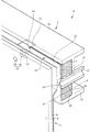
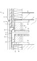
先ず、本実施形態に係る建物Hの基本構成について説明する。建物Hは、複数階建ての建物であり、各階の外縁部(換言すると、梁間方向における端部)には、図1〜図4に図示の外壁部1が設けられている。図1〜図4は、本実施形態に係る建物Hの外縁部を示す図であり、図1は、階間の外縁部を建物Hの外側から見た図であり、図2は、階間の外縁部を上方から見た図であり、図3は、階間の外縁部を図2のX−X面にて切断して見たときの図であり、図4は、階間の外縁部を図2のY−Y面にて切断して見たときの図である。なお、図1〜図3では、図示の都合上、一部の機器(例えば、後述の防火用ダンパ20)を簡略化して図示しており、また、図1では、一部の機器(例えば、フード21)の図示を省略している。
<< Basic Configuration of Building >>
First, the basic configuration of the building H according to the present embodiment will be described. The building H is a multi-storey building, and the
外壁部1は、図3及び図4に示すように、各階に配置された外壁パネル3と、上階の外壁パネル3と下階の外壁パネル3との間(すなわち、階間)に配置された面材4及び水切部材5と、を有する。面材4は、例えばサイディングボードによって構成されており、図2に示すように建物Hにおいて最も屋外側に配置されて露出している。水切部材5は、例えば金属板によって構成されており、図2に示すように面材4よりも屋内側で面材4と隣り合う位置に配置されている。
The
また、階間には、梁としての鉄骨梁2が設けられている。この鉄骨梁2は、H形鋼によって構成されており、建物Hの躯体中、胴差として機能する。具体的に説明すると、鉄骨梁2は、階間に設置されて上階の床を構成する部材、厳密には床パネル6を支持している。床パネル6は、オートクレーブ養生した軽量気泡コンクリート(Autoclaved Lightweight Concrete、以下、ALC)製のボード部材である。
Moreover, the
そして、床パネル6の直下位置には、比較的高さが低い空間(いわゆる床下懐であり、以下、階間空間V)が形成されている。換言すると、床パネル6は、階間空間Vを区画するために階間空間Vの直上位置に設けられ、被支持体として鉄骨梁2によって支持されている。なお、床パネル6は、図3に示すように、鉄骨梁2が有する上側のフランジ部2aの上端面に載置されることで、鉄骨梁2に支持されている。
Then, a space having a relatively low height (so-called under floor space, hereinafter referred to as inter-floor space V) is formed immediately below the
以上のように、階間の外縁部では、外壁部1と階間空間Vとの間で、鉄骨梁2が外壁部1と並ぶように配置されている。
As described above, at the outer edge between the floors, the
また、本実施形態の建物Hは、耐火仕様となっており、階間に設置された鉄骨梁2の周りには、所定の設置要領に則って耐火材7が設置されている。具体的に説明すると、耐火材7が、梁間方向において外壁部1と鉄骨梁2との間にて、鉄骨梁2が有するウェブ部2bの屋外側端面と隣り合うように設置されている。なお、本実施形態の耐火材7は、パネル状のロックウールからなり、図4に示すように、鉄骨梁2が有する上下一対のフランジ部2aの間に挟まれた状態で設置されている。すなわち、外壁部1と鉄骨梁2との間のスペースのうち、ウェブ部2bの屋外側端面と上下一対のフランジ部2aとによって囲まれる空間は、耐火材7が設置される設置空間S1に相当する。
Moreover, the building H of this embodiment is a fireproof specification, and the
なお、耐火材7の厚み(梁間方向における長さ)は、鉄骨梁2における各フランジ部2aの屋外側への張り出し量と同じ長さとなっている。したがって、耐火材7が設置空間S1に設置された状態において、耐火材7の屋外側の端位置は、フランジ部2aの屋外側の端位置と略揃っている。さらに、耐火材7は、鉄骨梁2の延出方向(すなわち、桁行方向)に沿って延びた状態で設置空間S1に設置されている。
In addition, the thickness (length in the direction between beams) of the
また、本実施形態の建物Hでは、不図示の換気ファンが階間空間Vに設置されており、この換気ファンを定期的に運転することによって、階間空間Vの換気を適宜実施している。すなわち、階間空間Vは、被換気空間に相当し、本実施形態では、建物Hの外側の空気を取り込むことで階間空間V内を換気することになっている。そして、本実施形態の建物Hでは、建物Hの外側の空気を円滑に階間空間V内に取り込めるような換気構造を採用している。特に、本実施形態では、階間空間Vを区画する床パネル6がALC製のボードによって構成されており、床パネル6中に吸着された水分(湿気)が階間空間V内に放出されるため、上記の換気構造が重要なものとなっている。
以下では、本実施形態の建物Hにて採用されている換気構造について詳しく説明することとする。
Moreover, in the building H of this embodiment, a ventilation fan (not shown) is installed in the inter-floor space V, and ventilation of the inter-floor space V is appropriately performed by operating the ventilation fan periodically. . That is, the inter-floor space V corresponds to a ventilated space, and in the present embodiment, the inside of the inter-floor space V is ventilated by taking in the air outside the building H. And in the building H of this embodiment, the ventilation structure which can take in the air of the outside of the building H smoothly in the space between floors V is adopted. In particular, in the present embodiment, the
Hereinafter, the ventilation structure employed in the building H of the present embodiment will be described in detail.
<<本実施形態の建物Hにおける換気構造>>
本実施形態の建物Hにて採用されている換気構造について、既出の図1〜4と共に図5〜図7を参照しながら説明する。図5は、囲い壁11及び仕切壁12が取り付けられた水切部材5を示す斜視図であり、水切部材5を屋内側から見た図である。図6及び図7は、本実施形態に係る建物Hの階間の外縁部における通気経路の説明図であり、図6は、図1中の仮想線A−Aを通る水平面にて階間の外縁部を切断して上方から見たときの図であり、図7は、階間の外縁部を図2のB−B面にて切断して屋外側から見たときの図である。なお、図7に図示の断面には、本来、通気孔14(厳密には、水切部材側通気孔16)が現れないが、説明の都合上、図7では、水切部材側通気孔16の位置を破線にて示している。
<< Ventilation structure in the building H of this embodiment >>
The ventilation structure employed in the building H of the present embodiment will be described with reference to FIGS. FIG. 5 is a perspective view showing the
本実施形態の建物Hにて採用されている換気構造は、建物Hの外縁部のうち、階間に相当する部分から建物Hの外側の空気を取り込み(吸気し)、その空気を階間空間V内に導くためのものである。なお、階間空間V内に空気を通し易くするために、階間空間V内の気圧は、若干負圧となるように調整される。 The ventilation structure employed in the building H of the present embodiment takes in (intakes) the air outside the building H from the portion corresponding to the floor in the outer edge of the building H, and the air is taken between the floors It is for leading in V. In addition, in order to facilitate the passage of air into the interfloor space V, the air pressure in the interfloor space V is adjusted to be slightly negative.
上記の換気構造は、図1〜図5に示すように、建物Hの階間の外縁部において通気経路を形成するために、外壁部1に設けられた通気孔14と、水切部材5の屋内側の表面に取り付けられた囲い壁11と、鉄骨梁2に設けられた貫通孔17と、貫通孔17に挿通された筒状部材としてのスリーブ13と、を有する。
The ventilating structure described above, as shown in FIGS. 1 to 5, includes a
通気孔14は、階間空間Vの換気を行うために外壁部1、厳密には、階間の外縁部に設けられた外壁部1に形成されている。より具体的に説明すると、通気孔14は、図3に示すように、階間に配置された面材4に設けられた面材側通気孔15と、水切部材5に設けられた水切部材側通気孔16と、を有している。面材側通気孔15及び水切部材側通気孔16は、図3に示すように、桁行方向及び鉛直方向において互いに同じ位置にある。
In order to ventilate the inter-floor space V, the air vents 14 are formed in the
なお、階間に配置された面材4の屋外側の表面には、面材側通気孔15の屋外側の開口を囲むようにフード21が取り付けられている。このフード21は、一般的な吸気用フードと同様の構成となっており、下端に開口(以下、「フード開口」と呼ぶ)を備えている。
In addition, the
囲い壁11は、本実施形態の第一部材に相当し、梁間方向において水切部材5と鉄骨梁2との間で水切部材側通気孔16と隣り合っている。より詳しく説明すると、囲い壁11は、図5に示すように、有底箱状に折り曲げ加工された鋼板からなり、水切部材側通気孔16の屋内側の開口を囲むように水切部材5の屋内側の表面に取り付けられている。つまり、囲い壁11は、水切部材5の屋内側の表面に接するように設けられている。
The
水切部材側通気孔16の周辺において囲い壁11によって囲まれた空間は、その上端が開放されている一方で上端以外が囲い壁11によって閉塞された空間となっている。また、囲い壁11によって囲まれた空間は、図3に示すように通気孔14(厳密には、面材側通気孔15及び水切部材側通気孔16)を介して建物Hの外側の空間と連通している。
The space surrounded by the surrounding
また、本実施形態では、囲い壁11によって囲まれた空間内に防火用ダンパ20の一部分(屋内側の部分)が収容されている。防火用ダンパ20は、建物Hの外側から炎が通気孔14を通じて建物H内に進入してきた際に、水切部材側通気孔16の屋内側の開口を塞ぎ、炎が更に屋内へ進入するのを防止する装置である。なお、防火用ダンパ20としては、通常時には開いており火災時等の緊急時に閉じるものである限り、一般的な防火用ダンパを用いることが可能である。
Further, in the present embodiment, a part of the fire prevention damper 20 (a part on the indoor side) is accommodated in the space surrounded by the
貫通孔17は、通気孔14を通過した空気を階間空間Vへ導くために鉄骨梁2のウェブ部2bに形成された円穴である。この貫通孔17は、階間空間Vを換気する際の空気の通路(風路)において通気孔14よりも階間空間Vに近い位置に設けられている。また、貫通孔17には、スリーブ13が挿入されている。スリーブ13は、本実施形態の第二部材に相当し、その一部分が貫通孔17の屋外側の開口から突出している。すなわち、スリーブ13のうち、貫通孔17の屋外側の開口から突出した部分は、梁間方向において水切部材5と鉄骨梁2との間で貫通孔17と隣り合っている。
The through holes 17 are circular holes formed in the
スリーブ13は、耐火被覆材(具体的には耐熱ロックウール)を筒状に成形したものであり、貫通孔17の径と同じ大きさの外径となっている。このスリーブ13が貫通孔17に挿入されて貫通孔17に嵌合する。
The
また、貫通孔17に挿入されたスリーブ13の内部空間は、図4に示すように、階間空間Vと連通している。
The internal space of the
また、前述したように、スリーブ13は、その一部分が貫通孔17の屋外側の開口から突出した状態で鉄骨梁2に取り付けられている。一方、鉄骨梁2のウェブ部2bの屋外側端面と上下一対のフランジ部2aとによって囲まれる空間(すなわち、設置空間S1)には、耐火材7が配置されている。また、耐火材7は、鉄骨梁2の延出方向(桁行方向)に沿って延びており、より具体的には、図1及び2に示すように、ウェブ部2bにおいて貫通孔17が設けられた箇所を通過するように延びている。
Further, as described above, the
さらに、耐火材7のうち、ウェブ部2bにおいて貫通孔17が設けられた箇所と対向する部分には、耐火材7を貫通して形成された円穴状のスリーブ通し孔18が設けられている。そして、スリーブ通し孔18には、スリーブ13中、貫通孔17の屋外側の開口から突出した部分が差し込まれている。なお、スリーブ13は、貫通孔17の屋外側の開口から突出した部分の端面が耐火材7の屋外側の端面と揃う位置まで、スリーブ通し孔18に差し込まれている。
Furthermore, in the portion of the refractory 7 facing the portion where the through
次に、建物Hの外側の空気を階間空間V内へ導くための通気経路について説明すると、建物Hの外側の空気は、フード開口(下端)を通じてフード21内に入り込み、さらに、面材側通気孔15及び水切部材側通気孔16を通って建物H内に入り込む。水切部材側通気孔16を通過した空気は、囲い壁11によって囲まれた空間を経由し、水切部材5と鉄骨梁2との間を移動する。このとき、空気は、囲い壁11(厳密には、囲い壁11のうち、水切部材側通気孔16の屋内側の開口と対向する部分)に衝突する。これにより、それまで面材4及び水切部材5を貫く方向に移動していた空気の移動方向が、図6に示すように略90度曲がるように変更される。以後、空気は、鉄骨梁2の延出方向に沿って水切部材5と鉄骨梁2との間を移動するようになる。
Next, the ventilation path for introducing the air outside the building H into the inter-story space V will be described. The air outside the building H enters the
なお、水切部材側通気孔16と対向する位置に囲い壁11が設けられているため、面材側通気孔15及び水切部材側通気孔16を通過する空気中に雨水等が混入していたとしても、囲い壁11によって、雨水等が更に屋内側に入り込むのを防止することが可能である。
In addition, since the surrounding
水切部材5と鉄骨梁2との間を移動した空気は、やがてスリーブ13の先端開口(屋外側の開口)からスリーブ13内に入り込み、スリーブ13の内部を移動する。これにより、空気は、鉄骨梁2の貫通孔17を通過し、スリーブ13の外に出た時点で階間空間V内に到達するようになる。
The air that has moved between the
本実施形態の建物Hでは、以上までに説明してきた換気構造によって階間空間Vの換気が行われるが、より適切に換気を行うための構成が更に採用されている。 In the building H of this embodiment, although the ventilation of the inter-floor space V is performed by the ventilation structure described above, a configuration for performing ventilation more appropriately is further adopted.
具体的に説明すると、本実施形態では、図1、図4、図6及び図7から分かるように、通気孔14(厳密には、面材側通気孔15及び水切部材側通気孔16)と貫通孔17とが、桁行方向及び鉛直方向において異なる位置に設けられている。これに対応するように、囲い壁11及びスリーブ13についても、桁行方向及び鉛直方向において異なる位置に配置されている。
Specifically, in the present embodiment, as can be seen from FIGS. 1, 4, 6, and 7, the vent holes 14 (strictly speaking, the face material side vent holes 15 and the water removing member side vent holes 16) The through
つまり、本実施形態の建物Hでは、水切部材5及び鉄骨梁2の間において、囲い壁11及びスリーブ13の各々の配置位置が互いにずれている。このように囲い壁11及びスリーブ13は、各々の配置位置がずれているため、互いに干渉せずに水切部材5及び鉄骨梁2の間にて適切に配置されている。
That is, in the building H of the present embodiment, the arrangement positions of the surrounding
なお、本実施形態では、図7に示すように、貫通孔17が通気孔14よりも上方に位置するように設けられている。したがって、通気孔14(厳密には、水切部材側通気孔16)を通過した空気は、図7に示すように、貫通孔17に向かって移動する過程で上昇し、その後に貫通孔17を通過する(すなわち、スリーブ13内を移動する)ようになる。
In the present embodiment, as shown in FIG. 7, the through
また、本実施形態では、図1〜図7に示すように、水切部材5及び鉄骨梁2の間には、仕切壁12が、桁行方向において囲い壁11と隣り合うように(厳密には、空気の移動方向において囲い壁11よりも下流側で囲い壁11と隣り合うように)設けられている。仕切壁12は、水切部材5及び鉄骨梁2の間において、耐火材7が設置される設置空間S1と、設置空間S1よりも屋外側に位置する非設置空間S2とを仕切るために設けられている。ここで、非設置空間S2とは、梁間方向において仕切壁12を挟んで設置空間S1と隣り合う空間であり、より厳密には、水切部材5よりも屋内側に位置し、かつ、鉄骨梁2のフランジ部2aにおける屋外側の端よりも屋外側に位置する空間である。
Further, in the present embodiment, as shown in FIGS. 1 to 7, the dividing
仕切壁12は、有底箱状に折り曲げ加工された鋼板からなり、水切部材5と共に一定の空間を囲むように水切部材5の屋内側の表面に取り付けられている。つまり、仕切壁12は、水切部材5の屋内側の表面に接するように設けられている。水切部材5と仕切壁12によって囲まれた空間は、その上端が開放されている一方で上端以外が水切部材5や仕切壁12によって閉塞された空間となっている。
The
また、本実施形態では、図2、図5及び図6から分かるように、水切部材5と仕切壁12によって囲まれた空間(換言すると、非設置空間S2のうち、仕切壁12と隣り合う空間)は、囲い壁11によって囲まれた空間と連通しており、厳密には連続している。そして、互いに連通している上記2つの空間(すなわち、水切部材5と仕切壁12によって囲まれた空間、及び囲い壁11によって囲まれた空間)は、通気孔14を通過した空気の通気経路をなしている。
Moreover, in this embodiment, as can be seen from FIGS. 2, 5 and 6, a space surrounded by the
以上のような仕切壁12が設けられて設置空間S1と非設置空間S2とが仕切られていることで、水切部材5及び鉄骨梁2の間にて通気経路が適切に確保されるようになる。より分かり易く説明すると、仕切壁12が設けられていない構成では、図8のように耐火材7の配置位置のズレや耐火材7自体の膨出によって、通気経路が耐火材7によって塞がれてしまう虞がある。図8は、通気経路が耐火材7によって塞がれた状況を示す図である。
By providing the
これに対して、本実施形態では仕切壁12を設けることで設置空間S1と非設置空間S2とが物理的に仕切られている。これにより、本実施形態では、通気経路が耐火材7によって塞がれてしまう状況を回避することが可能となる。なお、本実施形態において、仕切壁12(厳密には、仕切壁12のうち、鉄骨梁2の延出方向に沿って延びている部分)は、設置空間S1に設置された耐火材7の屋外側の表面に接している。
On the other hand, in the present embodiment, the installation space S1 and the non-installation space S2 are physically partitioned by providing the
仕切壁12において耐火材7の屋外側の表面に接している部分には、図1及び図4に示すように、スリーブ13の、貫通孔17の屋外側の開口から突出した部分の先端面が当接している。より詳しく説明すると、仕切壁12には、円穴状の貫通孔である壁貫通孔19が形成されている。壁貫通孔19は、第二の貫通孔に相当し、スリーブ13の突出部分の先端面が仕切壁12に当接している状態では、スリーブ13の屋外側の開口と重なっている。すなわち、鉄骨梁2の貫通孔17と、仕切壁12の壁貫通孔19とは、桁行方向及び鉛直方向において同じ位置に設けられている。これにより、水切部材5と鉄骨梁2との間に形成された通気経路中、水切部材5と仕切壁12によって囲まれた空間内を移動してきた空気は、壁貫通孔19を通じて貫通孔17(換言すると、スリーブ13の内部)を通過するようになる。
As shown in FIGS. 1 and 4, the end face of the portion of the
また、本実施形態では、囲い壁11及び仕切壁12が一部品として一体化している。より具体的に説明すると、本実施形態では、一つの鋼板を所定形状になるように(上面視で図2に図示の形状となるように)折り曲げ加工することで囲い壁11及び仕切壁12の双方を構成している。これにより、囲い壁11及び仕切壁12を水切部材5に取り付ける際には、双方の壁を同時に取り付けることが可能であり、建物Hの施工(具体的には、階間の換気構造を構築する作業)がより容易になる。
Moreover, in the present embodiment, the surrounding
<<その他の実施形態>>
以上までに本発明の建物について一例を挙げて説明したが、本発明の建物については、上述の実施形態以外の実施形態が考えられる。例えば、上記の実施形態では、通気孔14及び貫通孔17が桁行方向及び鉛直方向の両方向において異なる位置にあることとしたが、これに限定されるものではない。例えば、桁行方向及び鉛直方向のうち、いずれか一方の方向のみにおいて通気孔14及び貫通孔17が互いに異なる位置にあってもよい。
<< Other Embodiments >>
Although the example of the building of the present invention has been described above by way of example, embodiments of the present invention can be considered other than the above-described embodiment. For example, in the above embodiment, although the vent holes 14 and the through
また、上記の実施形態では、囲い壁11及び仕切壁12が一部品として一体化していることとしたが、これに限定されるものではない。囲い壁11及び仕切壁12が、それぞれ別部材によって構成されていて、互いに分離してもよい。
Moreover, in said embodiment, although the
また、上記の実施形態では、複数階建ての建物Hにおける階間空間Vの換気を行うための換気構造を例に挙げて説明した。ただし、本発明の換気構造は、屋根下に被換気空間を有する建物(例えば、陸屋根式の建物)において当該空間の換気を行う場合にも利用可能である。かかるケースでは、屋根材が被支持体として鉄骨梁2によって支持されることになるが、それ以外の構成については、上述した換気構造(階間空間Vを換気するための構造)と同様である。
なお、屋根下及び階間の双方に被換気空間が設けられているケースにおいて各々の空間の換気を行う場合にも、本発明の換気構造は、利用可能である。
さらに、本発明の換気構造は、居室等の部屋内を被換気空間とする場合にも利用可能である。
Further, in the above embodiment, the ventilation structure for ventilating the floor space V in the multi-storey building H has been described as an example. However, the ventilation structure of the present invention can also be used when ventilating the space in a building having a ventilated space under a roof (for example, a flat roof type building). In such a case, the roofing material is supported by the
The ventilation structure of the present invention can also be used when ventilating each space in the case where a ventilated space is provided both under the roof and between floors.
Furthermore, the ventilation structure of the present invention can also be used when the interior of a room such as a living room is a ventilated space.
また、上記の実施形態では、被換気空間(具体的には階間空間V)を換気するにあたり、外壁部1の通気孔14を通過した空気が鉄骨梁2の貫通孔17を通じて被換気空間へ導かれるケースを例に挙げて説明したが、これに限定されるものではない。すなわち、本発明は、被換気空間を換気するにあたり、被換気空間内の空気を、鉄骨梁2の貫通孔17及び外壁部1の通気孔14を通じて外気へ放出するケースにも適用し得る。
Further, in the above embodiment, in ventilating the ventilated space (specifically, the inter-floor space V), the air having passed through the vent holes 14 of the
1 外壁部
2 鉄骨梁(梁)
2a フランジ部
2b ウェブ部
3 外壁パネル
4 面材
5 水切部材
6 床パネル(被支持体)
7 耐火材
11 囲い壁
12 仕切壁
13 スリーブ(筒状部材)
14 通気孔
15 面材側通気孔
16 水切部材側通気孔
17 貫通孔
18 スリーブ通し孔
19 壁貫通孔(第二の貫通孔)
20 防火用ダンパ
21 フード
H 建物
S1 設置空間
S2 非設置空間
V 階間空間(被換気空間)
1
7
14
20
Claims (9)
該建物の外縁部に設けられた外壁部と、
該外壁部と並ぶように設けられた梁と、
前記被換気空間の換気を行うために前記外壁部に形成された通気孔と、
前記梁に形成されており、前記被換気空間を換気する際の空気の通路において前記通気孔よりも前記被換気空間に近い位置に設けられた貫通孔と、
少なくとも一部分が前記外壁部と前記梁との間で前記通気孔と隣り合った第一部材と、
少なくとも一部分が前記外壁部と前記梁との間で前記貫通孔と隣り合った第二部材と、を有し、
前記外壁部と前記梁とが並ぶ方向と交差する方向において、前記通気孔及び前記貫通孔が異なる位置にあることを特徴とする建物。 A building with a ventilated space,
An outer wall provided at the outer edge of the building;
A beam provided parallel to the outer wall,
A vent formed in the outer wall to ventilate the ventilated space;
A through hole formed in the beam and provided at a position closer to the ventilated space than the vent in a passage of air when ventilating the ventilated space;
A first member at least a part of which is adjacent to the vent between the outer wall and the beam;
A second member at least a part of which is adjacent to the through hole between the outer wall and the beam;
A building characterized in that the vent holes and the through holes are in different positions in a direction intersecting the direction in which the outer wall portion and the beam are arranged.
前記筒状部材の内部と前記被換気空間が連通していることを特徴とする請求項1に記載の建物。 The second member is a cylindrical member which is inserted into the through hole and a portion thereof protrudes from an opening on the outdoor side of the through hole,
The building according to claim 1, wherein the interior of the cylindrical member and the ventilated space communicate with each other.
該囲い壁によって囲まれた空間と前記建物の外側の空間とが、前記通気孔を介して連通していることを特徴とする請求項1又は2に記載の建物。 The first member is an enclosure wall disposed to surround an opening on the indoor side of the vent,
The building according to claim 1 or 2, wherein the space surrounded by the surrounding wall and the space outside the building communicate with each other through the vent.
前記外壁部と前記梁との間において、前記耐火材が設置される設置空間と、該設置空間よりも屋外側に位置する非設置空間とを仕切るために設けられた仕切壁と、を有することを特徴とする請求項3に記載の建物。 A refractory material provided between the outer wall portion and the beam so as to be adjacent to the end face on the outdoor side of the web portion of the beam;
Between the outer wall portion and the beam, an installation space in which the refractory material is installed, and a partition wall provided to divide a non-installation space located on the outdoor side of the installation space. The building according to claim 3, characterized in that
前記非設置空間中、前記仕切壁と隣り合う空間と、前記囲い壁によって囲まれた空間とは、互いに連続しており、前記通気孔を通過した空気の通気経路をなしていることを特徴とする請求項4に記載の建物。 The partition wall is provided between the outer wall portion and the beam so as to be adjacent to the enclosure wall.
In the non-installation space, a space adjacent to the partition wall and a space surrounded by the surrounding wall are continuous with each other, and form an air flow path of air having passed through the air hole. The building according to claim 4.
前記貫通孔及び前記第二の貫通孔は、前記外壁部と前記梁とが並ぶ方向と交差する方向において同じ位置にあることを特徴とする請求項5に記載の建物。 The partition wall is provided with a second through hole,
The building according to claim 5, wherein the through hole and the second through hole are at the same position in a direction intersecting the direction in which the outer wall portion and the beam are arranged.
前記通気孔は、前記面材に設けられた面材側通気孔と、前記水切部材に設けられた水切部材側通気孔を有し、
前記第一部材は、前記水切部材の屋内側の表面に接するように設けられ、
前記外壁部と前記梁とが並ぶ方向と交差する方向において、前記面材側通気孔及び前記水切部材側通気孔は、同じ位置にあることを特徴とする請求項1乃至7のいずれか一項に記載の建物。 The outer wall portion includes a facing exposed on the outdoor side, and a drainage member disposed indoors more than the facing.
The air vent has a face material side air vent provided in the face material and a water removing member side air vent provided in the water removing member.
The first member is provided in contact with the indoor surface of the drainage member,
The face material side vent hole and the drainage member side vent hole are in the same position in the direction intersecting with the direction in which the outer wall portion and the beam are arranged. The building described in.
前記被支持体は、軽量気泡コンクリートによって構成されていることを特徴とする請求項1乃至8のいずれか一項に記載の建物。 A support is provided immediately above the vented space to partition the vented space, and is supported by the beam.
The building according to any one of claims 1 to 8, wherein the support is made of lightweight cellular concrete.
Priority Applications (1)
| Application Number | Priority Date | Filing Date | Title |
|---|---|---|---|
| JP2017185264A JP6978883B2 (en) | 2017-09-26 | 2017-09-26 | building |
Applications Claiming Priority (1)
| Application Number | Priority Date | Filing Date | Title |
|---|---|---|---|
| JP2017185264A JP6978883B2 (en) | 2017-09-26 | 2017-09-26 | building |
Publications (2)
| Publication Number | Publication Date |
|---|---|
| JP2019060126A true JP2019060126A (en) | 2019-04-18 |
| JP6978883B2 JP6978883B2 (en) | 2021-12-08 |
Family
ID=66176362
Family Applications (1)
| Application Number | Title | Priority Date | Filing Date |
|---|---|---|---|
| JP2017185264A Active JP6978883B2 (en) | 2017-09-26 | 2017-09-26 | building |
Country Status (1)
| Country | Link |
|---|---|
| JP (1) | JP6978883B2 (en) |
Cited By (2)
| Publication number | Priority date | Publication date | Assignee | Title |
|---|---|---|---|---|
| JP2021188436A (en) * | 2020-06-03 | 2021-12-13 | 日本インシュレーション株式会社 | Fireproof structure of horizontal lumber |
| JP7196274B1 (en) | 2021-12-23 | 2022-12-26 | 株式会社ユニックス | Silent ventilation member |
Citations (2)
| Publication number | Priority date | Publication date | Assignee | Title |
|---|---|---|---|---|
| JP2002004448A (en) * | 2000-06-26 | 2002-01-09 | Daiwa House Ind Co Ltd | Ventilation structure between stories |
| JP2013164229A (en) * | 2012-02-13 | 2013-08-22 | Tokyu Construction Co Ltd | Silencing ventilation device |
-
2017
- 2017-09-26 JP JP2017185264A patent/JP6978883B2/en active Active
Patent Citations (2)
| Publication number | Priority date | Publication date | Assignee | Title |
|---|---|---|---|---|
| JP2002004448A (en) * | 2000-06-26 | 2002-01-09 | Daiwa House Ind Co Ltd | Ventilation structure between stories |
| JP2013164229A (en) * | 2012-02-13 | 2013-08-22 | Tokyu Construction Co Ltd | Silencing ventilation device |
Cited By (4)
| Publication number | Priority date | Publication date | Assignee | Title |
|---|---|---|---|---|
| JP2021188436A (en) * | 2020-06-03 | 2021-12-13 | 日本インシュレーション株式会社 | Fireproof structure of horizontal lumber |
| JP7490455B2 (en) | 2020-06-03 | 2024-05-27 | 日本インシュレーション株式会社 | Fireproof structure of cross members |
| JP7196274B1 (en) | 2021-12-23 | 2022-12-26 | 株式会社ユニックス | Silent ventilation member |
| JP2023094435A (en) * | 2021-12-23 | 2023-07-05 | 株式会社ユニックス | Silent ventilation member |
Also Published As
| Publication number | Publication date |
|---|---|
| JP6978883B2 (en) | 2021-12-08 |
Similar Documents
| Publication | Publication Date | Title |
|---|---|---|
| JP2019060126A (en) | building | |
| JP2023105144A (en) | Building | |
| JP2012007374A (en) | Curtain wall | |
| JP2010084368A (en) | Ventilation structure | |
| JP2011006908A (en) | Curtain wall | |
| JP7827532B2 (en) | Inter-floor space structure | |
| JP2021004510A (en) | Heat insulating structure | |
| JP5684499B2 (en) | Building ventilation structure | |
| JP3143015U (en) | Duct integrated ventilation louver | |
| JP3798592B2 (en) | Building ventilation structure | |
| JP4846328B2 (en) | Architectural wall body with flame barrier function, building with flame barrier function, and fire prevention method for building | |
| JP5342051B2 (en) | Building shed ventilation structure | |
| JP6974997B2 (en) | building | |
| JP6475999B2 (en) | Building ceiling structure | |
| JP6958224B2 (en) | Wall ventilation structure | |
| JP2016188470A (en) | Flat roof ventilation structure | |
| JP2011185039A (en) | Wall body for construction with fire shielding function and construction with fire shielding function as well as fire protection method of construction | |
| JP2017160730A (en) | Attic ventilation structure and ventilation member | |
| JPH0122015Y2 (en) | ||
| JP2013238026A (en) | Structure for supporting eave soffit plate of building | |
| JP4885599B2 (en) | Underfloor ventilation structure | |
| JP2017066660A (en) | Solar radiation heat control structure | |
| JP2007146570A (en) | Ventilation structure behind the hut | |
| JP4060780B2 (en) | Building | |
| JP2024021215A (en) | Building |
Legal Events
| Date | Code | Title | Description |
|---|---|---|---|
| A621 | Written request for application examination |
Free format text: JAPANESE INTERMEDIATE CODE: A621 Effective date: 20200909 |
|
| A977 | Report on retrieval |
Free format text: JAPANESE INTERMEDIATE CODE: A971007 Effective date: 20210609 |
|
| A131 | Notification of reasons for refusal |
Free format text: JAPANESE INTERMEDIATE CODE: A131 Effective date: 20210622 |
|
| A521 | Request for written amendment filed |
Free format text: JAPANESE INTERMEDIATE CODE: A523 Effective date: 20210812 |
|
| TRDD | Decision of grant or rejection written | ||
| A01 | Written decision to grant a patent or to grant a registration (utility model) |
Free format text: JAPANESE INTERMEDIATE CODE: A01 Effective date: 20211026 |
|
| A61 | First payment of annual fees (during grant procedure) |
Free format text: JAPANESE INTERMEDIATE CODE: A61 Effective date: 20211112 |
|
| R150 | Certificate of patent or registration of utility model |
Ref document number: 6978883 Country of ref document: JP Free format text: JAPANESE INTERMEDIATE CODE: R150 |
|
| R250 | Receipt of annual fees |
Free format text: JAPANESE INTERMEDIATE CODE: R250 |