JP2017116027A - Bolt removal prevention material - Google Patents
Bolt removal prevention material Download PDFInfo
- Publication number
- JP2017116027A JP2017116027A JP2015253779A JP2015253779A JP2017116027A JP 2017116027 A JP2017116027 A JP 2017116027A JP 2015253779 A JP2015253779 A JP 2015253779A JP 2015253779 A JP2015253779 A JP 2015253779A JP 2017116027 A JP2017116027 A JP 2017116027A
- Authority
- JP
- Japan
- Prior art keywords
- bolt
- prevention material
- cylindrical
- fastened
- fastened member
- Prior art date
- Legal status (The legal status is an assumption and is not a legal conclusion. Google has not performed a legal analysis and makes no representation as to the accuracy of the status listed.)
- Granted
Links
Images




Landscapes
- Bolts, Nuts, And Washers (AREA)
Abstract
【課題】被締結部材に対する作業性が良いボルト抜け防止材を提供する。【解決手段】ボルト抜け防止材1は、ボルト挿入孔1aを形成する金属製の内側嵌入部12と、内側嵌入部12の外側に設けられた外側嵌入部11とを有する筒状部と、筒状部からボルト挿入孔1aの内方に突出し、ボルト2のネジ部2Cと係合可能な突出部と、内側嵌入部12の軸方向の端部から外方に突出するフランジ部13と、を備える。外側嵌入部11は、内側嵌入部12を構成する金属材料よりも高い弾性を有する材料により構成されている。【選択図】図3[Problem] To provide a bolt slip-out prevention material that is easy to work with on fastened components. [Solution] The bolt slip-out prevention material (1) comprises a cylindrical portion having a metallic inner fitting portion (12) that forms a bolt insertion hole (1a) and an outer fitting portion (11) provided on the outside of the inner fitting portion (12), a protruding portion that protrudes from the cylindrical portion into the bolt insertion hole (1a) and is engageable with the threaded portion (2C) of the bolt (2), and a flange portion (13) that protrudes outward from the axial end of the inner fitting portion (12). The outer fitting portion (11) is made of a material that has higher elasticity than the metallic material that makes up the inner fitting portion (12). [Selected Figure] Figure 3
Description
本発明は、被締結部材に締結されたボルトが抜けるのを防止するボルト抜け防止材に関する。 The present invention relates to a bolt drop prevention material that prevents a bolt fastened to a member to be fastened from coming off.
従来より、被締結部材に対して締結されたボルトが抜け落ちるのを防止するボルト抜け防止材が提案されている(例えば、特許文献1参照)。特許文献1のボルト抜け防止材は、ボルト係合部を有して略有蓋円筒状をなし、被締結部材の、ボルトが挿入される側に対する反対側に形成された取付孔に挿入されて、ボルトのネジ山にボルト係合部を係合させることにより、ボルトの抜けを防止している。 Conventionally, a bolt slip-off preventing material that prevents a bolt fastened to a fastened member from falling off has been proposed (see, for example, Patent Document 1). The bolt disengagement prevention material of Patent Document 1 has a bolt engaging portion and has a substantially covered cylindrical shape, and is inserted into an attachment hole formed on the opposite side of the member to be fastened to the side on which the bolt is inserted, The bolt engagement part is engaged with the screw thread of the bolt to prevent the bolt from coming off.
しかし、特許文献1のボルト抜け防止材は、作業者から見てボルトを挿入する側とは反対側に挿入する必要があるため、作業性が悪かった。 However, since the bolt disengagement prevention material of Patent Document 1 needs to be inserted on the side opposite to the side where the bolt is inserted as viewed from the operator, workability is poor.
そこで本発明は、被締結部材に対する作業性が良いボルト抜け防止材を提供することを目的とする。 Therefore, an object of the present invention is to provide a bolt slip-off preventing material with good workability for a fastened member.
上記目的を解決するために、本発明の一態様であるボルト抜け防止材は、ボルト挿入孔を形成する内側部と、前記内側部の外側に設けられた外側部とを有する筒状部と、前記筒状部から前記ボルト挿入孔の内方に突出し、ボルトのネジ部と係合可能な突出部と、前記筒状部の軸方向の端部から外方に突出するフランジ部と、を備えている。前記筒状部の前記内側部は、金属材料により構成され、前記筒状部の前記外側部は、前記筒状部の前記内側部を構成する金属材料よりも高い弾性を有する材料により構成されても良い。 In order to solve the above-described object, a bolt drop prevention material according to an aspect of the present invention includes an inner part that forms a bolt insertion hole, and a cylindrical part that has an outer part provided outside the inner part, A protruding portion that protrudes inward of the bolt insertion hole from the tubular portion and engageable with a screw portion of the bolt; and a flange portion that protrudes outward from an end portion in the axial direction of the tubular portion. ing. The inner part of the cylindrical part is made of a metal material, and the outer part of the cylindrical part is made of a material having higher elasticity than the metal material constituting the inner part of the cylindrical part. Also good.
また、前記筒状部は、金属製の第1被締結部材に形成された嵌入孔に嵌め入れ可能であり、前記筒状部の前記外側部は、前記第1被締結部材を構成する金属材料よりも高い弾性を有する材料により構成されても良い。 Moreover, the said cylindrical part can be inserted in the insertion hole formed in the metal 1st to-be-fastened member, The said outer side part of the said cylindrical part is a metal material which comprises the said 1st to-be-fastened member It may be made of a material having higher elasticity.
また、前記突出部は、前記筒状部の前記内側部から前記ボルト挿入孔の内方に突出していても良い。 The protruding portion may protrude inward of the bolt insertion hole from the inner side portion of the cylindrical portion.
また、前記筒状部の前記内側部には、貫通孔が形成され、前記突出部は、前記筒状部の前記外側部に設けられ、前記内側部の前記貫通孔を貫通して、前記ボルト挿入孔の内方に突出していても良い。 Further, a through hole is formed in the inner part of the cylindrical part, and the protruding part is provided in the outer part of the cylindrical part, penetrates the through hole of the inner part, and the bolt You may protrude inward of the insertion hole.
また、前記筒状部の前記外側部は、前記フランジ部側とは反対側に向かってテーパ状をなしていても良い。 The outer portion of the cylindrical portion may be tapered toward the opposite side to the flange portion side.
また、前記ボルトを第1被締結部材の嵌入孔に挿入して、第2被締結部材のネジ孔に螺合させて、前記第1被締結部材と前記第2被締結部材とを締結した場合、前記筒状部が、前記ボルトを挿入する側から前記第1被締結部材の前記嵌入孔に嵌め入れられ、前記突出部が、前記ボルトのネジ部に係合し、前記フランジ部は、前記第1被締結部材に当接しかつ前記ボルトのヘッドを支持しても良い。 When the bolt is inserted into the insertion hole of the first member to be fastened and screwed into the screw hole of the second member to be fastened to fasten the first member to be fastened and the second member to be fastened. The cylindrical portion is inserted into the insertion hole of the first fastened member from the side where the bolt is inserted, the protruding portion is engaged with a screw portion of the bolt, and the flange portion is You may contact | abut to a 1st to-be-fastened member and support the head of the said volt | bolt.
本発明によれば、被締結部材に対する組立性が良く、かつ、ボルトを被締結部材に締める又は緩める際の作業性が良いボルト抜け防止材を提供することができる。 ADVANTAGE OF THE INVENTION According to this invention, the assembly | attachment property with respect to a to-be-fastened member is good, and the workability | operativity at the time of tightening or loosening a bolt to a to-be-fastened member can be provided.
本発明の一実施形態によるボルト抜け防止材について、図面を参照して説明する。 A bolt drop prevention material according to an embodiment of the present invention will be described with reference to the drawings.
図1は、第1の実施の形態に係るボルト抜け防止材1を用いて、ボルト2により第1、第2被締結部材3、4を締結する方法を説明するための図を示す。図2は、図1に示したボルト抜け防止材1、第1、第2被締結部材3、4の一部を切り欠いた状態を示す図である。
FIG. 1 is a diagram for explaining a method of fastening first and second fastened
図1、2に示すように、ボルト2は、ヘッド2Aと、シャンク2Bとを有し、シャンク2Bの外周部には、ネジ部2C(図5)が形成されている。第1被締結部材3は、金属製(例えば、ステンレス鋼(SUS304))の板材であり、上下に貫通する嵌入孔3aが形成されている。第2被締結部材4は、金属製(例えば、鋼材(SPCC))の板材であり、上下に貫通するネジ孔4aが形成されている。第1被締結部材3の嵌入孔3aは、第2被締結部材4のネジ孔4aよりも大きく構成されている。
As shown in FIGS. 1 and 2, the
例えば、第2被締結部材4は、半導体製造装置等に用いる流体制御装置の複数本のガスラインを収容する筐体のうち、ガスラインをメンテナンスするための開口を形成する周囲部分に相当し、第1被締結部材3は、当該開口を覆うためのカバーに相当する。
For example, the second fastened
次に、ボルト抜け防止材1について図3〜図5を参照して詳細に説明する。 Next, the bolt drop prevention material 1 will be described in detail with reference to FIGS.
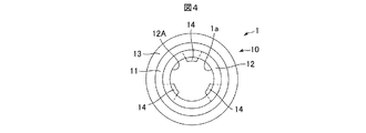
図3は、ボルト抜け防止材1の斜視図を示し、図4は、ボルト抜け防止材1の底面図を示し、図5は、ボルト抜け防止材1を用いて、ボルト2により第1、第2被締結部材3、4を締結した状態における、ボルト抜け防止材1、第1、第2被締結部材3、4を図2の切断面で切った断面図を示す。
3 is a perspective view of the bolt drop prevention material 1, FIG. 4 is a bottom view of the bolt drop prevention material 1, and FIG. 2 is a cross-sectional view of the bolt drop prevention material 1, the first and second fastened
ボルト抜け防止材1は、ボルト挿入孔1aを有し、例えば、ステンレス鋼(SUSXM7)により構成されるボルト2と同等またはそれ以上の剛性を有する金属材料(例えば、ステンレス鋼(SUS304))により構成された本体部10と、円筒状の外側嵌入部11とを備える。
The bolt drop prevention material 1 has a
本体部10は、内側嵌入部12と、フランジ部13と、3個の突出部14とを有する。内側嵌入部12は、円筒状をなし、その内周面12Aによりボルト挿入孔1aを形成する。フランジ部13は、内側嵌入部12の軸方向の端部から径方向の外方に突出している。このように、内側嵌入部12と、フランジ部13とは一体的に構成されている。フランジ部13の外径は、第1被締結部材3の嵌入孔3aの内径よりも大きく構成されている。3個の突出部14は、内側嵌入部12の内周面12Aからボルト挿入孔1aの内方に突出し、周方向に等間隔に設けられている。
The
外側嵌入部11は、円筒状をなし、本体部10および第1被締結部材3を構成する各金属材料より高い弾性を有する金属材料(例えば、アルミニウム)または合成樹脂材料(例えば、PTFE(ポリテトラフルオロエチレン))により構成されている。外側嵌入部11は、内側嵌入部12の外周に設けられている。外側嵌入部11および内側嵌入部12により、筒状部が構成される。外側嵌入部11は、筒状部の外側部に相当し、内側嵌入部12は、筒状部の内側部に相当する。外側嵌入部11の外径は、第1被締結部材3の嵌入孔3aの内径よりも僅かに大きく構成されている。
The
次に、本実施形態のボルト抜け防止材1を用いて、ボルト2により第1被締結部材3と第2被締結部材4とを締結する方法の一例について説明する。
Next, an example of a method for fastening the first fastened
初めに、ボルト2を挿入する側から、第1被締結部材3の嵌入孔3aに、ボルト抜け防止材1の筒状部(外側嵌入部11および内側嵌入部12)を嵌め入れる。外側嵌入部11の外径は、嵌入孔3aの内径よりも、僅かに大きく構成され、かつ外側嵌入部11は、本体部10および第1被締結部材3を構成する金属材料より高い弾性を有する材料により構成されているので、弾性変形(縮径)した状態で嵌入(圧入)される。本体部10のフランジ部13は、第1被締結部材3に当接する。
First, from the side where the
次に、ボルト抜け防止材1が装着された第1被締結部材3を第2被締結部材4に対し、第1被締結部材3の嵌入孔3aが第2被締結部材4のネジ孔4aに連通するように重ねる。ボルト2をボルト抜け防止材1のボルト挿入孔1aに回転させながら挿入し、ボルト2のネジ部2Cと、第2被締結部材4のネジ孔4aとを螺合させる。ボルト2のネジ部2Cと、第2被締結部材4のネジ孔4aとを螺合させた状態において、突出部14はボルト2のネジ部2Cと係合(接触)しており、ボルト2のヘッド2Aが、ボルト抜け防止材1のフランジ部13に当接している。
Next, with respect to the second member to be fastened 4 to which the first member to be fastened 3 to which the bolt disengagement prevention material 1 is attached, the
以上のように、本実施形態のボルト抜け防止材1は、ボルト挿入孔1aを形成する金属製の内側嵌入部12と内側嵌入部12の外側に設けられた外側嵌入部11とを有する筒状部と、内側嵌入部12からボルト挿入孔1aの内方に突出し、ボルト2のネジ部2Cと係合可能な突出部14と、内側嵌入部12の軸方向の端部から外方に突出するフランジ部13と、を備える。外側嵌入部11は、内側嵌入部12を構成する金属材料よりも高い弾性を有する材料により構成されている。
As described above, the bolt drop prevention material 1 of the present embodiment has a cylindrical shape including the metal
ボルト2を第1被締結部材3の嵌入孔3aに挿入して、第2被締結部材4のネジ孔4aに螺合させて、第1被締結部材3と第2被締結部材4とを締結した場合、内側嵌入部12および外側嵌入部11から構成される筒状部が、ボルト2を挿入する側から第1被締結部材3の嵌入孔3aに嵌め入れられ、突出部14が、ボルト2のネジ部2Cに係合し、フランジ部13は、第1被締結部材3に当接しかつボルト2のヘッド2Aを支持する。
The
かかる構成により、作業者は、ボルト2を挿入する側からボルト抜け防止材1を、第1被締結部材3に取り付けることができるので、ボルト抜け防止材1の組立性を向上させることができる。また、ボルト抜け防止材1が第1被締結部材3の嵌入孔3aに嵌め入れられた状態で、ボルト2により第1被締結部材3および第2被締結部材4を締結するので、作業性を向上させることができる。
With this configuration, the operator can attach the bolt drop prevention material 1 to the first fastened
また、ボルト抜け防止材1が第1被締結部材3の嵌入孔3aに嵌め入れられ、嵌入されたボルト抜け防止材1に設けられた突出部14とボルト2のネジ部2Cが係合するので、ボルト2の抜けを防止することができる。フランジ部13は、第1被締結部材3に当接して、ボルト2のヘッド2Aを支持するので、フランジ部13を座金として機能させることができる。このように、ボルト抜け防止材1は、ボルト2の抜け防止および座金の2つの機能を有する。
Moreover, since the bolt drop prevention material 1 is fitted into the
内側嵌入部12および外側嵌入部11により構成された筒状部は、金属製の第1被締結部材3に形成された嵌入孔3aに嵌め入れ可能であり、外側嵌入部11は、第1被締結部材3を構成する金属材料よりも高い弾性を有する材料により構成されている。かかる構成により、外側嵌入部11を第1被締結部材3に対し弾性変形させて容易に嵌入させることができる。
The cylindrical portion formed by the
次に、本発明の第2の実施の形態に係るボルト抜け防止材101について、図6、7を参照して説明する。
Next, a bolt
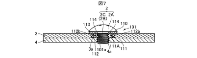
図6は、第2の実施の形態に係るボルト抜け防止材101の斜視図を示し、図7は、第2の実施の形態に係るボルト抜け防止材101を用いて、ボルト2により第1、第2被締結部材3、4を締結した状態における、図2に相当するボルト抜け防止材101、第1、第2被締結部材3、4の断面図を示す。
FIG. 6 shows a perspective view of the bolt
ボルト抜け防止材101は、ボルト挿入孔101aを有し、第1の実施の形態に係るボルト抜け防止材1の本体部10と同様の金属材料により構成された本体部110と、円筒状の外側嵌入部111とを備える。
The bolt
本体部110は、内側嵌入部112と、フランジ部113とを有する。内側嵌入部112は、円筒状をなし、その内周面112Aによりボルト挿入孔101aを形成する。内側嵌入部112には、内側嵌入部112を径方向に貫通する貫通孔112bが3カ所に等間隔に形成されている。なお、図6、7では、2カ所の貫通孔112bのみを示している。フランジ部113は、内側嵌入部112の軸方向の端部から径方向の外方に突出している。このように、内側嵌入部112と、フランジ部113とは一体的に構成されている。フランジ部113の外径は、第1被締結部材3の嵌入孔3aの内径よりも大きく構成されている。
The
外側嵌入部111は、円筒状をなし、本体部110、第1被締結部材3、およびボルト2を構成する各金属材料より高い弾性(低い剛性)を有する金属材料(例えば、アルミニウム)または合成樹脂材料(例えば、PTFE)により構成されている。外側嵌入部111は、内側嵌入部112の外周に設けられている。外側嵌入部111および内側嵌入部112により、筒状部が構成される。外側嵌入部111は、筒状部の外側部に相当し、内側嵌入部112は、筒状部の内側部に相当する。外側嵌入部111の外径は、第1被締結部材3の嵌入孔3aの内径よりも僅かに大きく構成されている。
The
また、外側嵌入部111には、3個の突出部114が、内面111Aに周方向に等間隔に設けられている。各突出部114は、内側嵌入部112の対応する貫通孔112bを貫通して、ボルト挿入孔101aの内方に突出している。また、ボルト挿入孔101aの軸から各突出部114の先端までの距離は、ボルト2のシャンク2Bの軸からネジ部2Cのネジ山の先端までの距離よりも短くなるように構成されている。
Moreover, the three
本実施の形態のボルト抜け防止材101においても、第1の実施の形態のボルト抜け防止材1と同様の効果を奏することができる。また、突出部114は、ボルト2を構成する金属材料より高い弾性(低い剛性)を有する金属材料または合成樹脂材料により構成されているので、図7に示すように、突出部114の先端が、ボルト2のネジ部2Cのネジ山に対し、嵌り込み、ボルト2の抜けをより防止することができる。
The bolt
なお、本発明は、上述した実施例に限定されない。当業者であれば、本発明の範囲内で、種々の追加や変更等を行うことができる。 In addition, this invention is not limited to the Example mentioned above. A person skilled in the art can make various additions and changes within the scope of the present invention.
例えば、上記の実施形態において、外側嵌入部11、111は、フランジ部13、113側とは反対側に向かってテーパ状をなしていても良い。突出部14、114は、3カ所に設けられていたが、突出部14、114の数は、これに限らず、必要に応じた数を設けても良い。また、第1、2被締結部材3、4は、流体制御装置の筐体を構成する部材であったが、これに限らず、他の装置の筐体を構成する部材であっても良い。
For example, in the above embodiment, the outer
1、101:ボルト抜け防止材
1a、101a:ボルト挿入孔
2:ボルト
2A:ヘッド
2C:ネジ部
3:第1被締結部材
3a:嵌入孔
4:第2被締結部材
4a:ネジ孔
10、110:本体部
11、111:外側嵌入部
12、112:内側嵌入部
13、113:フランジ部
14、114:突出部
DESCRIPTION OF SYMBOLS 1, 101: Bolt drop
Claims (7)
前記筒状部から前記ボルト挿入孔の内方に突出し、ボルトのネジ部と係合可能な突出部と、
前記筒状部の軸方向の端部から外方に突出するフランジ部と、を備えた、ボルト抜け防止材。 A cylindrical part having an inner part forming a bolt insertion hole, and an outer part provided outside the inner part;
A protruding portion that protrudes inward of the bolt insertion hole from the cylindrical portion and is engageable with a screw portion of the bolt;
A bolt drop prevention material comprising: a flange portion protruding outward from an axial end portion of the tubular portion.
前記筒状部の前記外側部は、前記筒状部の前記内側部を構成する金属材料よりも高い弾性を有する材料により構成された、請求項1に記載のボルト抜け防止材。 The inner part of the cylindrical part is made of a metal material,
2. The bolt drop prevention material according to claim 1, wherein the outer portion of the tubular portion is made of a material having higher elasticity than a metal material constituting the inner portion of the tubular portion.
前記筒状部の前記外側部は、前記第1被締結部材を構成する金属材料よりも高い弾性を有する材料により構成された、請求項2に記載のボルト抜け防止材。 The cylindrical part can be fitted into a fitting hole formed in the first fastening member made of metal,
The bolt drop prevention material according to claim 2, wherein the outer portion of the cylindrical portion is made of a material having higher elasticity than a metal material constituting the first fastened member.
前記突出部は、前記筒状部の前記外側部に設けられ、前記内側部の前記貫通孔を貫通して、前記ボルト挿入孔の内方に突出している、請求項1から請求項3のいずれか一項に記載のボルト抜け防止材。 A through hole is formed in the inner portion of the cylindrical portion,
The said protrusion part is provided in the said outer side part of the said cylindrical part, penetrates the said through hole of the said inner side part, and protrudes inward of the said bolt insertion hole. The bolt drop prevention material according to claim 1.
前記筒状部が、前記ボルトを挿入する側から前記第1被締結部材の前記嵌入孔に嵌め入れられ、前記突出部が、前記ボルトの前記ネジ部に係合し、前記フランジ部は、前記第1被締結部材に当接しかつ前記ボルトのヘッドを支持する、請求項1から請求項6のいずれか一項に記載のボルト抜け防止材。
When the bolt is inserted into the insertion hole of the first fastened member and screwed into the screw hole of the second fastened member to fasten the first fastened member and the second fastened member,
The cylindrical portion is fitted into the insertion hole of the first fastened member from the side where the bolt is inserted, the protruding portion engages with the screw portion of the bolt, and the flange portion The bolt disengagement prevention material according to any one of claims 1 to 6, which contacts the first fastened member and supports the head of the bolt.
Priority Applications (1)
| Application Number | Priority Date | Filing Date | Title |
|---|---|---|---|
| JP2015253779A JP6722448B2 (en) | 2015-12-25 | 2015-12-25 | Bolt removal prevention material |
Applications Claiming Priority (1)
| Application Number | Priority Date | Filing Date | Title |
|---|---|---|---|
| JP2015253779A JP6722448B2 (en) | 2015-12-25 | 2015-12-25 | Bolt removal prevention material |
Publications (2)
| Publication Number | Publication Date |
|---|---|
| JP2017116027A true JP2017116027A (en) | 2017-06-29 |
| JP6722448B2 JP6722448B2 (en) | 2020-07-15 |
Family
ID=59233913
Family Applications (1)
| Application Number | Title | Priority Date | Filing Date |
|---|---|---|---|
| JP2015253779A Active JP6722448B2 (en) | 2015-12-25 | 2015-12-25 | Bolt removal prevention material |
Country Status (1)
| Country | Link |
|---|---|
| JP (1) | JP6722448B2 (en) |
Cited By (1)
| Publication number | Priority date | Publication date | Assignee | Title |
|---|---|---|---|---|
| JP2020072068A (en) * | 2018-11-02 | 2020-05-07 | 横河電機株式会社 | Module connection structure and measuring instrument |
Citations (4)
| Publication number | Priority date | Publication date | Assignee | Title |
|---|---|---|---|---|
| JPS60172024U (en) * | 1984-04-24 | 1985-11-14 | 内山工業株式会社 | seal wax shear |
| JP2000136816A (en) * | 1998-11-02 | 2000-05-16 | Hitachi Chem Co Ltd | Fastening auxiliary part, object, object with fastening auxiliary part, and fastening method for object |
| JP2008111467A (en) * | 2006-10-30 | 2008-05-15 | Okano Kiko Kk | Reinforcement collar |
| JP2008133899A (en) * | 2006-11-28 | 2008-06-12 | Fujitsu Access Ltd | Screw-fastening structure |
-
2015
- 2015-12-25 JP JP2015253779A patent/JP6722448B2/en active Active
Patent Citations (4)
| Publication number | Priority date | Publication date | Assignee | Title |
|---|---|---|---|---|
| JPS60172024U (en) * | 1984-04-24 | 1985-11-14 | 内山工業株式会社 | seal wax shear |
| JP2000136816A (en) * | 1998-11-02 | 2000-05-16 | Hitachi Chem Co Ltd | Fastening auxiliary part, object, object with fastening auxiliary part, and fastening method for object |
| JP2008111467A (en) * | 2006-10-30 | 2008-05-15 | Okano Kiko Kk | Reinforcement collar |
| JP2008133899A (en) * | 2006-11-28 | 2008-06-12 | Fujitsu Access Ltd | Screw-fastening structure |
Cited By (2)
| Publication number | Priority date | Publication date | Assignee | Title |
|---|---|---|---|---|
| JP2020072068A (en) * | 2018-11-02 | 2020-05-07 | 横河電機株式会社 | Module connection structure and measuring instrument |
| US11031963B2 (en) | 2018-11-02 | 2021-06-08 | Yokogawa Electric Corporation | Module connection structure and measuring instrument |
Also Published As
| Publication number | Publication date |
|---|---|
| JP6722448B2 (en) | 2020-07-15 |
Similar Documents
| Publication | Publication Date | Title |
|---|---|---|
| JP3220889U (en) | Washer built-in nut | |
| CN107781270B (en) | Screw with washer | |
| US20080145179A1 (en) | Sleeve | |
| JP6408448B2 (en) | Screw device | |
| US20110064537A1 (en) | Two-Part Device | |
| EP2493040B1 (en) | Cable gland | |
| JP2013238286A (en) | Clip | |
| JP2017116027A (en) | Bolt removal prevention material | |
| US10781923B2 (en) | Cover, seal fitting device, and seal fitting method | |
| JP2021116871A (en) | Seal washer | |
| JP2007315580A (en) | Washer for preventing bolt from loosening | |
| JP2013104494A (en) | Thin plate fixing structure | |
| JP2020092515A (en) | Cable gland | |
| JP2018007340A (en) | Cable gland | |
| JP6576901B2 (en) | Bolt / nut locking structure | |
| JP2009074609A (en) | Press-in-spacer nut | |
| JP2008180340A (en) | Nail for concrete | |
| JP6804387B2 (en) | Fixing mechanism and mechanical seal | |
| KR20100126931A (en) | Fastening unit | |
| JP2005140314A (en) | Washer with suitable fastening torque indication | |
| KR20170003488U (en) | Housing having invisible coupling structure | |
| JP6284873B2 (en) | Fastener | |
| JP2016084850A (en) | Corporation cock device and assembling method thereof | |
| JP2015183764A (en) | Idle pulley device for internal combustion engine | |
| US11422013B2 (en) | Sensor housing |
Legal Events
| Date | Code | Title | Description |
|---|---|---|---|
| A621 | Written request for application examination |
Free format text: JAPANESE INTERMEDIATE CODE: A621 Effective date: 20181025 |
|
| A131 | Notification of reasons for refusal |
Free format text: JAPANESE INTERMEDIATE CODE: A131 Effective date: 20190924 |
|
| A977 | Report on retrieval |
Free format text: JAPANESE INTERMEDIATE CODE: A971007 Effective date: 20190919 |
|
| RD02 | Notification of acceptance of power of attorney |
Free format text: JAPANESE INTERMEDIATE CODE: A7422 Effective date: 20191023 |
|
| A521 | Request for written amendment filed |
Free format text: JAPANESE INTERMEDIATE CODE: A523 Effective date: 20191113 |
|
| A02 | Decision of refusal |
Free format text: JAPANESE INTERMEDIATE CODE: A02 Effective date: 20200212 |
|
| A521 | Request for written amendment filed |
Free format text: JAPANESE INTERMEDIATE CODE: A523 Effective date: 20200407 |
|
| A911 | Transfer to examiner for re-examination before appeal (zenchi) |
Free format text: JAPANESE INTERMEDIATE CODE: A911 Effective date: 20200416 |
|
| TRDD | Decision of grant or rejection written | ||
| A01 | Written decision to grant a patent or to grant a registration (utility model) |
Free format text: JAPANESE INTERMEDIATE CODE: A01 Effective date: 20200602 |
|
| A61 | First payment of annual fees (during grant procedure) |
Free format text: JAPANESE INTERMEDIATE CODE: A61 Effective date: 20200622 |
|
| R150 | Certificate of patent or registration of utility model |
Ref document number: 6722448 Country of ref document: JP Free format text: JAPANESE INTERMEDIATE CODE: R150 |
|
| R250 | Receipt of annual fees |
Free format text: JAPANESE INTERMEDIATE CODE: R250 |
|
| R250 | Receipt of annual fees |
Free format text: JAPANESE INTERMEDIATE CODE: R250 |
|
| R250 | Receipt of annual fees |
Free format text: JAPANESE INTERMEDIATE CODE: R250 |