JP2013062242A - Method of manufacturing thin film for thin film solid secondary battery, coating liquid used therefor, thin film, and thin film solid secondary battery using the same - Google Patents
Method of manufacturing thin film for thin film solid secondary battery, coating liquid used therefor, thin film, and thin film solid secondary battery using the same Download PDFInfo
- Publication number
- JP2013062242A JP2013062242A JP2012184729A JP2012184729A JP2013062242A JP 2013062242 A JP2013062242 A JP 2013062242A JP 2012184729 A JP2012184729 A JP 2012184729A JP 2012184729 A JP2012184729 A JP 2012184729A JP 2013062242 A JP2013062242 A JP 2013062242A
- Authority
- JP
- Japan
- Prior art keywords
- thin film
- active material
- material layer
- oxide
- electrode active
- Prior art date
- Legal status (The legal status is an assumption and is not a legal conclusion. Google has not performed a legal analysis and makes no representation as to the accuracy of the status listed.)
- Pending
Links
Images




Classifications
-
- Y—GENERAL TAGGING OF NEW TECHNOLOGICAL DEVELOPMENTS; GENERAL TAGGING OF CROSS-SECTIONAL TECHNOLOGIES SPANNING OVER SEVERAL SECTIONS OF THE IPC; TECHNICAL SUBJECTS COVERED BY FORMER USPC CROSS-REFERENCE ART COLLECTIONS [XRACs] AND DIGESTS
- Y02—TECHNOLOGIES OR APPLICATIONS FOR MITIGATION OR ADAPTATION AGAINST CLIMATE CHANGE
- Y02E—REDUCTION OF GREENHOUSE GAS [GHG] EMISSIONS, RELATED TO ENERGY GENERATION, TRANSMISSION OR DISTRIBUTION
- Y02E60/00—Enabling technologies; Technologies with a potential or indirect contribution to GHG emissions mitigation
- Y02E60/10—Energy storage using batteries
-
- Y—GENERAL TAGGING OF NEW TECHNOLOGICAL DEVELOPMENTS; GENERAL TAGGING OF CROSS-SECTIONAL TECHNOLOGIES SPANNING OVER SEVERAL SECTIONS OF THE IPC; TECHNICAL SUBJECTS COVERED BY FORMER USPC CROSS-REFERENCE ART COLLECTIONS [XRACs] AND DIGESTS
- Y02—TECHNOLOGIES OR APPLICATIONS FOR MITIGATION OR ADAPTATION AGAINST CLIMATE CHANGE
- Y02P—CLIMATE CHANGE MITIGATION TECHNOLOGIES IN THE PRODUCTION OR PROCESSING OF GOODS
- Y02P70/00—Climate change mitigation technologies in the production process for final industrial or consumer products
- Y02P70/50—Manufacturing or production processes characterised by the final manufactured product
Landscapes
- Battery Electrode And Active Subsutance (AREA)
- Sealing Battery Cases Or Jackets (AREA)
- Cell Electrode Carriers And Collectors (AREA)
- Secondary Cells (AREA)
Abstract
Description
本発明は、薄膜固体二次電池用の薄膜の製造方法とそれに用いる塗布液、及びその製造方法による薄膜、並びにその薄膜を用いた薄膜固体二次電池に関するものである。
より詳しくは、集電体層(正極、負極)、及び正極活物質層、固体電解質層、負極活物質層の各薄膜を有する薄膜固体二次電池において、それら各薄膜の形成を塗布法という簡便な方法により行う薄膜の製造方法とそれに用いる塗布液、及びその製造方法で得られる薄膜を適用することで、薄型化、小型化、低コスト化を図ることが可能な薄膜固体二次電池に関するものである。
The present invention relates to a method for producing a thin film for a thin film solid secondary battery, a coating solution used therefor, a thin film produced by the production method, and a thin film solid secondary battery using the thin film.
More specifically, in a thin-film solid secondary battery having a current collector layer (positive electrode, negative electrode) and a thin film of a positive electrode active material layer, a solid electrolyte layer, and a negative electrode active material layer, the formation of each thin film is simply called a coating method. A thin film solid-state secondary battery that can be reduced in thickness, size, and cost by applying a thin film manufacturing method and a coating solution used therefor, and a thin film obtained by the manufacturing method. It is.
リチウムイオン二次電池は、エネルギー密度が大きく、充放電のサイクル特性に優れるため、携帯機器等の電子機器を中心に広く使用されている。 Lithium ion secondary batteries have a large energy density and are excellent in charge / discharge cycle characteristics, and thus are widely used mainly in electronic devices such as portable devices.
一般的なリチウムイオン二次電池は、正極、負極、電解液、セパレータの基本要素で構成され、正極、及び負極は、これら電極間に電解質を保持できるセパレータを介在させた状態で電解液に浸漬され、容器で覆われている。
さらに、上記正極、及び負極は、それぞれの活物質(正極活物質、負極活物質)の結晶性粒子、導電材、結合材等を集電体(金属箔、金属メッシュ等)が保持し、構成されて利用されている。
A typical lithium ion secondary battery is composed of basic elements of a positive electrode, a negative electrode, an electrolytic solution, and a separator. The positive electrode and the negative electrode are immersed in the electrolytic solution with a separator that can hold an electrolyte between the electrodes. And covered with a container.
Further, the positive electrode and the negative electrode have a structure in which current collectors (metal foil, metal mesh, etc.) hold crystalline particles, conductive materials, binders, etc. of the respective active materials (positive electrode active material, negative electrode active material). Has been used.
正極活物質にはリチウムと遷移金属を含む複合酸化物が用いられている。具体的には、層状系材料としてのコバルト酸リチウム(LiCoO2)、ニッケル酸リチウム(LiNiO2)、リチウム−ニッケル−マンガン−コバルト酸化物(LiNi1/3Mn1/3Co1/3O2)、スピネル系材料としてのリチウム−マンガン酸化物(LiMn2O4)、オリビン系材料としてのリン酸鉄リチウム(LiFePO4)等が一般的である。
負極活物質としては、黒鉛(グラファイト)、チタン酸リチウム(Li4Ti5O12)等が一般的に用いられている。
A composite oxide containing lithium and a transition metal is used for the positive electrode active material. Specifically, lithium cobaltate (LiCoO 2 ), lithium nickelate (LiNiO 2 ), and lithium-nickel-manganese-cobalt oxide (LiNi 1/3 Mn 1/3 Co 1/3 O 2 as layered materials. ), Lithium-manganese oxide (LiMn 2 O 4 ) as a spinel material, lithium iron phosphate (LiFePO 4 ) as an olivine material, and the like are common.
As the negative electrode active material, graphite (graphite), lithium titanate (Li 4 Ti 5 O 12 ) or the like is generally used.
しかしながら、液体である電解液を電解質として用いるリチウムイオン二次電池では、小型化、薄型化に限界があり、ゲル状電解質を用いるポリマー電池や固体電解質を用いる薄膜固体二次電池が開発されている。
このなかで、薄膜固体二次電池では、その構造が基板上に正極集電体層、正極活物質層、固体電解質層、負極活物質層、負極集電体層を順に形成した積層構造、あるいは、基板上に上記層を逆の順で形成した積層構造を採り、基板を除く電池素子部分の厚みを1μm程度にすることができ、電池全体の薄型化、小型化をより一層図ることが可能である。
However, in lithium ion secondary batteries using a liquid electrolyte as an electrolyte, there are limits to miniaturization and thinning, and polymer batteries using gel electrolytes and thin film solid secondary batteries using solid electrolytes have been developed. .
Among these, in a thin film solid secondary battery, the structure is a laminated structure in which a positive electrode current collector layer, a positive electrode active material layer, a solid electrolyte layer, a negative electrode active material layer, and a negative electrode current collector layer are sequentially formed on a substrate, or The laminated structure in which the above layers are formed in the reverse order on the substrate is adopted, and the thickness of the battery element portion excluding the substrate can be reduced to about 1 μm, thereby further reducing the thickness and size of the entire battery. It is.
特に、固体電解質を用いた薄膜固体二次電池は、小型化、薄型化が可能という利点に加え、電位窓が広いためLiに対して高電位の正極活物質(5V系)の適用により高容量化が可能で、また、一つのセル内で積層する直列化による高電圧化が容易なため低コスト化が図れ、更に、固体電解質の優れた耐熱性や難燃性による安全性向上も期待できる。 In particular, a thin-film solid-state secondary battery using a solid electrolyte has a high potential by applying a positive electrode active material (5 V system) having a high potential with respect to Li in addition to the advantage that it can be reduced in size and thickness, and has a wide potential window. In addition, it is possible to reduce the cost because it is easy to increase the voltage by serially stacking in one cell, and it is also expected to improve the safety due to the excellent heat resistance and flame resistance of the solid electrolyte .
使用する固体電解質には、リン酸リチウム(Li3PO4)、リン酸リチウムに窒素を添加したLi3PO4NX(LiPONと呼ばれる。)等の酸化物系固体電解質や酸化物系固体電解質に比べて導電性の高いLi2S−P2S5等の硫化物系固体電解質が用いられている。 Solid electrolytes used include oxide-based solid electrolytes and oxide-based solid electrolytes such as lithium phosphate (Li 3 PO 4 ) and Li 3 PO 4 N X (referred to as LiPON) in which nitrogen is added to lithium phosphate. In contrast, sulfide-based solid electrolytes such as Li 2 S—P 2 S 5 having higher conductivity are used.
このような固体電解質を用いた薄膜固体二次電池としては、スパッタリング法等の物理的成膜方法(気相成長方法)を用いて正極活物質層、固体電解質層、負極活物質層の薄膜を形成したものが提案されている(特許文献1〜4等参照)。 As a thin film solid secondary battery using such a solid electrolyte, a thin film of a positive electrode active material layer, a solid electrolyte layer, and a negative electrode active material layer is formed using a physical film formation method (vapor phase growth method) such as a sputtering method. What was formed is proposed (refer patent documents 1-4).
特許文献1には、イオンビームや電子ビーム蒸着法による成膜法を用いて、リン酸リチウム(Li3PO4)に窒素が添加された物質(LiPON)の固体電解質層、リチウムを含む金属酸化物の正極活物質層、金属リチウムの負極活物質層を形成した薄膜固体二次電池が開示されている。
特許文献2には、スパッタリング法による成膜法を用いて、リチウムイオン伝導体(イオン伝導度の高いLi、Ta、Nb、N、Oから成る複合酸化物)の固体電解質層、リチウムを含む金属酸化物(LiCoO2やLiMn2O4等)の正極活物質層、SiやLi4Ti5O12等の負極活物質層を形成した薄膜固体二次電池が開示されている。
特許文献3には、スパッタリング法による成膜法を用いて、リン酸リチウム(Li3PO4)に窒素が添加された物質(LiPON)の固体電解質層、遷移金属およびリチウムを含む金属酸化物の正極活物質層、半導体、金属、合金または金属酸化物のいずれかの負極活物質層を形成した薄膜固体二次電池が開示されている。
特許文献4には、スパッタリング法による成膜法を用いて、窒素が添加されたリン酸リチウム(LiPON)の固体電解質層、リチウム−コバルト酸化物の正極活物質層、金属リチウムの負極活物質層を形成した薄膜固体二次電池が開示されている。
さらに、特許文献5においてもスパッタリング法による成膜法を用いて、リン酸リチウム(Li3PO4)または窒素が添加されたリン酸リチウム(LiPON)の固体電解質層、リチウム−マンガン酸化物、リチウム−コバルト酸化物、リチウム−ニッケル酸化物、リチウム−マンガン−コバルト酸化物、リチウム−チタン酸化物のいずれか一つ以上の金属酸化物の正極活物質層、リチウム−チタン−ニオブ複合酸化物の負極活物質層を形成した薄膜固体二次電池が開示されている。
Further, in
以上のように、従来の薄膜固体二次電池における、正極活物質層、固体電解質層、負極活物質層の各薄膜の成膜には、イオン・電子ビーム蒸着、直流スパッタ法、RFマグネトロンスパッタ法等の物理的成膜方法(気相成長方法)が用いられている。 As described above, in the conventional thin film solid secondary battery, each thin film of the positive electrode active material layer, the solid electrolyte layer, and the negative electrode active material layer is formed by ion / electron beam evaporation, direct current sputtering, RF magnetron sputtering. Such a physical film formation method (vapor phase growth method) is used.
しかしながら、薄膜固体二次電池の正極活物質層、固体電解質層、負極活物質層の各薄膜を、スパッタリング法などの物理的成膜方法(気相成長方法)で成膜する場合、使用する成膜装置は真空容器をベースとする装置となるため非常に高価であり、また成膜される膜の組成制御も容易ではなく、かつ成膜する材料によっては成膜速度を大きくできないため、製造コストと量産性に問題があった。
そこで、正極活物質層、固体電解質層、負極活物質層の各薄膜をより簡便な方法で形成する成膜方法が望まれていた。
However, when the thin film of the positive electrode active material layer, the solid electrolyte layer, and the negative electrode active material layer of the thin film solid secondary battery is formed by a physical film formation method (vapor phase growth method) such as a sputtering method, it is used. The film device is very expensive because it is based on a vacuum vessel, and the composition control of the film to be formed is not easy, and the film formation speed cannot be increased depending on the material to be formed. And there was a problem with mass productivity.
Therefore, a film forming method for forming each thin film of the positive electrode active material layer, the solid electrolyte layer, and the negative electrode active material layer by a simpler method has been desired.
本発明は、集電体層(正極、負極)、及び正極活物質層、固体電解質層、負極活物質層の各薄膜を有する薄膜固体二次電池において、低コストかつ簡便な塗布法により上記各薄膜を形成する方法とそれに用いる塗布液、及びその方法により得られる各薄膜、並びにその各薄膜を用いた薄型化、小型化、低コスト化が図られた薄膜固体二次電池の提供を目的とする。 The present invention provides a thin film solid secondary battery having a current collector layer (positive electrode, negative electrode) and a thin film of a positive electrode active material layer, a solid electrolyte layer, and a negative electrode active material layer. The object is to provide a method for forming a thin film, a coating solution used therefor, each thin film obtained by the method, and a thin film solid state secondary battery that is thinned, miniaturized and reduced in cost using each thin film. To do.
発明者らは、このような状況に鑑み、有機金属化合物を主成分として含有する(正極、負極)活物質層形成用塗布液や電解質層形成用塗布液を、塗布、乾燥、無機化して得られる金属酸化物を主成分とする無機薄膜について鋭意研究を重ねた結果、その無機化の工程で、酸素含有雰囲気下で加熱処理、エネルギー線照射処理、プラズマ照射処理の少なくともいずれかの処理を行えば無機化が促進されて、正極活物質層、固体電解質層、負極活物質層の各薄膜に適した金属酸化物を主成分とする無機薄膜が得られることを見出したものである。 In view of such a situation, the inventors obtained a coating solution for forming an active material layer or a coating solution for forming an electrolyte layer containing an organometallic compound as a main component (positive electrode, negative electrode) by applying, drying and mineralizing. As a result of extensive research on inorganic thin films mainly composed of metal oxides, at least one of heat treatment, energy ray irradiation treatment, and plasma irradiation treatment was performed in an oxygen-containing atmosphere during the mineralization process. For example, it has been found that mineralization is promoted, and an inorganic thin film mainly composed of a metal oxide suitable for each thin film of the positive electrode active material layer, the solid electrolyte layer, and the negative electrode active material layer can be obtained.
即ち、本発明の第1の発明は、基板上に順次形成されている正極集電体層、正極活物質層、固体電解質層、負極活物質層、負極集電体層から成る積層構造、あるいは、これと逆の順に基板上に形成されている負極集電体層、負極活物質層、固体電解質層、正極活物質層、正極集電体層から成る積層構造を有する薄膜固体二次電池における正極活物質層、固体電解質層、負極活物質層の少なくとも一つ以上の薄膜の製造方法であって、その薄膜が、主成分として有機金属化合物を含有する正極活物質層形成用塗布液、固体電解質層形成用塗布液、負極活物質層形成用塗布液から選択されるいずれかの塗布液を塗布して塗布膜を形成する塗布工程、塗布膜を乾燥して乾燥塗布膜を形成する乾燥工程、乾燥工程で形成された有機金属化合物を主成分とする乾燥塗布膜を無機化して、金属酸化物を主成分とする無機薄膜を形成する無機化工程の各工程からなる塗布法により形成され、その無機化工程が、酸素含有雰囲気下で加熱処理、エネルギー線照射処理、プラズマ照射処理の少なくともいずれかの処理により乾燥塗布膜に含まれる有機成分を分解または酸化、あるいは分解および酸化により除去することで金属酸化物を主成分とする微粒子で構成される無機薄膜(金属酸化物微粒子膜)を形成する工程であることを特徴とするものである。 That is, the first invention of the present invention is a laminated structure comprising a positive electrode current collector layer, a positive electrode active material layer, a solid electrolyte layer, a negative electrode active material layer, and a negative electrode current collector layer sequentially formed on a substrate, or In a thin film solid secondary battery having a laminated structure comprising a negative electrode current collector layer, a negative electrode active material layer, a solid electrolyte layer, a positive electrode active material layer, and a positive electrode current collector layer formed on the substrate in the reverse order. A method for producing at least one thin film of a positive electrode active material layer, a solid electrolyte layer, and a negative electrode active material layer, wherein the thin film contains an organometallic compound as a main component, a coating liquid for forming a positive electrode active material layer, a solid A coating process for forming a coating film by applying any coating liquid selected from a coating liquid for forming an electrolyte layer and a coating liquid for forming a negative electrode active material layer, and a drying process for drying the coating film to form a dry coating film The main component is an organometallic compound formed in the drying process Formed by a coating method comprising each step of the mineralization step of mineralizing the dry coating film to form an inorganic thin film containing a metal oxide as a main component, and the mineralization step is a heat treatment in an oxygen-containing atmosphere. It consists of fine particles mainly composed of metal oxides by decomposing or oxidizing or removing organic components contained in the dried coating film by decomposition or oxidation by at least one of energy beam irradiation treatment and plasma irradiation treatment. This is a process for forming an inorganic thin film (metal oxide fine particle film).
本発明の第2の発明は、第1の発明における正極活物質層形成用塗布液に主成分として含有される有機金属化合物が、マンガン、コバルト、ニッケル、鉄のうちのいずれか一種以上の遷移金属の有機金属化合物、及び有機リチウム化合物であり、形成された無機薄膜の主成分である金属酸化物が、マンガン、コバルト、ニッケル、鉄のいずれか一種以上の遷移金属を含むリチウム複合酸化物であることを特徴とする薄膜の製造方法である。 In the second invention of the present invention, the organometallic compound contained as a main component in the coating liquid for forming a positive electrode active material layer in the first invention is a transition of any one or more of manganese, cobalt, nickel, and iron. A metal organic metal compound and an organic lithium compound, and the metal oxide that is the main component of the formed inorganic thin film is a lithium composite oxide containing one or more transition metals of manganese, cobalt, nickel, and iron. There is a method for producing a thin film.
本発明の第3の発明は、第2の発明におけるリチウム複合酸化物が、LiMO2、LiMPO4、Li2MSiO4(M:マンガン、コバルト、ニッケル、鉄のうちのいずれか一種以上の遷移金属)、LiMn2O4のいずれか一種以上であることを特徴とする薄膜の製造方法である。 According to a third aspect of the present invention, the lithium composite oxide in the second aspect is LiMO 2 , LiMPO 4 , Li 2 MSiO 4 (M: one or more transition metals of manganese, cobalt, nickel, iron) ), LiMn 2 O 4 , and a method for producing a thin film.
本発明の第4の発明は、第1の発明における固体電解質層形成用塗布液に主成分として含有される有機金属化合物が、有機リン化合物と有機リチウム化合物であり、形成された無機薄膜の主成分である金属酸化物が、リンを含むリチウム複合酸化物であることを特徴とする薄膜の製造方法である。 According to a fourth aspect of the present invention, the organometallic compound contained as a main component in the coating solution for forming a solid electrolyte layer according to the first aspect is an organophosphorus compound and an organolithium compound. The metal oxide as a component is a lithium composite oxide containing phosphorus.
本発明の第5の発明は、第4の発明におけるリンを含むリチウム複合酸化物が、Li3PO4、Li2O−Al2O3−TiO2−P2O5系酸化物、Li2O−Al2O3−GeO2−P2O5系酸化物、Li2O−La2O3−TiO2系酸化物、Li2O−La2O3−ZrO2系酸化物のいずれか一種以上であることを特徴とする薄膜の製造方法である。
In a fifth aspect of the present invention, the lithium composite oxide containing phosphorus in the fourth aspect is Li 3 PO 4 , Li 2 O—Al 2 O 3 —TiO 2 —P 2 O 5 based oxide, Li 2 O-Al 2 O 3 -GeO 2 -P 2
本発明の第6の発明は、第1の発明における固体電解質層形成用塗布液に主成分として含有される有機金属化合物が、有機ランタン化合物と有機リチウム化合物であり、形成された無機薄膜の主成分である金属酸化物が、ランタンを含むリチウム複合酸化物であることを特徴とする薄膜の製造方法である。 According to a sixth aspect of the present invention, the organic metal compound contained as a main component in the coating solution for forming a solid electrolyte layer according to the first aspect is an organic lanthanum compound and an organic lithium compound, The metal oxide as a component is a lithium composite oxide containing lanthanum, which is a method for producing a thin film.
本発明の第7の発明は、第6の発明におけるランタンを含むリチウム複合酸化物が、Li2O−La2O3−TiO2系酸化物、Li2O−La2O3−ZrO2系酸化物のいずれか一種以上であることを特徴とする薄膜の製造方法である。 In a seventh aspect of the present invention, the lithium composite oxide containing lanthanum according to the sixth aspect is Li 2 O—La 2 O 3 —TiO 2 oxide, Li 2 O—La 2 O 3 —ZrO 2 It is a manufacturing method of the thin film characterized by being 1 or more types of an oxide.
本発明の第8の発明は、第1の発明における負極活物質層形成用塗布液に主成分として含有される有機金属化合物が、有機チタン化合物と有機リチウム化合物、または、ニオブ、インジウム、錫、亜鉛、チタンのいずれか一種以上の金属の有機金属化合物であり、形成された無機薄膜の主成分である金属酸化物が、リチウム−チタン酸化物、酸化ニオブ、酸化インジウム、酸化錫、酸化亜鉛、酸化チタンのいずれか一種以上であることを特徴とする薄膜の製造方法である。 According to an eighth aspect of the present invention, the organometallic compound contained as a main component in the coating liquid for forming a negative electrode active material layer according to the first aspect is an organic titanium compound and an organic lithium compound, or niobium, indium, tin, An organic metal compound of one or more metals of zinc and titanium, and the metal oxide that is the main component of the formed inorganic thin film is lithium-titanium oxide, niobium oxide, indium oxide, tin oxide, zinc oxide, It is a manufacturing method of a thin film characterized by being one or more of titanium oxides.
本発明の第9の発明は、第8の発明におけるリチウム−チタン酸化物がLi4Ti5O12であることを特徴とする薄膜の製造方法である。 A ninth aspect of the present invention is a method for producing a thin film, characterized in that the lithium-titanium oxide in the eighth aspect is Li 4 Ti 5 O 12 .
本発明の第10の発明は、第1〜第9の発明におけるエネルギー線照射が、少なくとも200nm以下の波長を主要成分の一つとして含む紫外線の照射であることを特徴とする薄膜の製造方法である。 A tenth invention of the present invention is a method for producing a thin film, characterized in that the energy beam irradiation in the first to ninth inventions is irradiation of ultraviolet rays containing at least a wavelength of 200 nm or less as one of main components. is there.
本発明の第11の発明は、第10の発明における少なくとも200nm以下の波長を主要成分の一つとして含む紫外線の照射が、低圧水銀ランプ、アマルガムランプ、エキシマランプのいずれかから放射される紫外線の照射であることを特徴とする薄膜の製造方法である。 In an eleventh aspect of the present invention, the irradiation of ultraviolet rays containing at least a wavelength of 200 nm or less as one of the main components in the tenth aspect is ultraviolet rays emitted from any one of a low-pressure mercury lamp, an amalgam lamp, and an excimer lamp. A thin film manufacturing method characterized by irradiation.
本発明の第12の発明は、第1〜第11の発明における酸素含有雰囲気の露点温度の制御により、金属酸化物を主成分とする無機薄膜の充填密度を制御することを特徴とする薄膜の製造方法である。 According to a twelfth aspect of the present invention, there is provided a thin film characterized by controlling the packing density of an inorganic thin film mainly composed of a metal oxide by controlling the dew point temperature of the oxygen-containing atmosphere in the first to eleventh aspects. It is a manufacturing method.
本発明の第13の発明は、第1〜第12の発明における酸素含有雰囲気が空気雰囲気であることを特徴とする薄膜の製造方法である。 A thirteenth aspect of the present invention is a method for producing a thin film characterized in that the oxygen-containing atmosphere in the first to twelfth aspects is an air atmosphere.
本発明の第14の発明は、第1の発明における基板がガラス基板、またはセラミック基板、あるいは耐熱性プラスチックフィルムであることを特徴とする薄膜の製造方法である。 A fourteenth aspect of the present invention is a method for producing a thin film, wherein the substrate in the first aspect is a glass substrate, a ceramic substrate, or a heat-resistant plastic film.
本発明の第15の発明は、第1の発明における正極集電体層、及び負極集電体層が、単一金属または合金であることを特徴とする薄膜の製造方法である。 A fifteenth aspect of the present invention is a method for producing a thin film, characterized in that the positive electrode current collector layer and the negative electrode current collector layer in the first invention are a single metal or an alloy.
本発明の第16の発明は、第1の発明における正極集電体層、または負極集電体層が形成された基板の代わりに、正極集電体層、または負極集電体層として単一金属または合金から成る板または箔を用いることを特徴とする薄膜の製造方法である。 In the sixteenth aspect of the present invention, a single positive electrode current collector layer or negative electrode current collector layer is used instead of the substrate on which the positive electrode current collector layer or the negative electrode current collector layer is formed. A thin film manufacturing method characterized by using a plate or foil made of a metal or an alloy.
本発明の第17の発明は、第1〜第9の発明における薄膜の製造方法に用いられる、正極活物質層形成用塗布液、固体電解質層形成用塗布液、負極活物質層形成用塗布液から選択されるいずれかの塗布液であって、正極活物質層形成用塗布液は、有機溶剤、及びその有機溶剤中に溶解した、主成分としての、マンガン、コバルト、ニッケル、鉄のうちのいずれか一種以上の遷移金属の有機金属化合物、及び有機リチウム化合物を含有し、固体電解質層形成用塗布液は、有機溶剤、及びその有機溶剤中に溶解した、主成分としての、有機リン化合物と有機リチウム化合物、あるいは、有機ランタン化合物と有機リチウム化合物を含有し、負極活物質層形成用塗布液は、有機溶剤、及びその有機溶剤中に溶解した、主成分としての、有機チタン化合物と有機リチウム化合物を含有し、有機リチウム化合物は、リチウム(I)−2,4−ペンタンジオネート[Li(C5H7O2)]、リチウム(I)エトキシド[Li(C2H5O)]、リチウム(I)−tert−ブトキシド[Li(C4H9O)]のうちのいずれか一種以上であり、有機溶剤は、N−メチル−2−ピロリドン、沸点150℃以上のアミン系溶剤のうちのいずれか一種以上であることを特徴とする塗布液である。 According to a seventeenth aspect of the present invention, there is provided a coating solution for forming a positive electrode active material layer, a coating solution for forming a solid electrolyte layer, and a coating solution for forming a negative electrode active material layer, which are used in the method for producing a thin film according to the first to ninth aspects. The positive electrode active material layer forming coating solution is selected from the group consisting of an organic solvent and a main component dissolved in the organic solvent, of manganese, cobalt, nickel, and iron. An organic metal compound of any one or more transition metals and an organic lithium compound, and the coating solution for forming a solid electrolyte layer includes an organic solvent and an organic phosphorus compound as a main component dissolved in the organic solvent. An organic lithium compound, or an organic lanthanum compound and an organic lithium compound, and the coating liquid for forming a negative electrode active material layer is an organic solvent and an organic titanate as a main component dissolved in the organic solvent. Containing objects and organolithium compounds, organolithium compounds, lithium (I)-2,4-pentanedionate [Li (C 5 H 7 O 2)], lithium (I) ethoxide [Li (C 2 H 5 O)], lithium (I) -tert-butoxide [Li (C 4 H 9 O)], and the organic solvent is N-methyl-2-pyrrolidone, an amine having a boiling point of 150 ° C. or higher. It is a coating liquid characterized by being one or more of the system solvents.
本発明の第18の発明は、第17の発明における沸点150℃以上のアミン系溶剤が、3−アミノ−1−プロパノールであることを特徴とする塗布液である。 An eighteenth aspect of the present invention is a coating liquid characterized in that the amine solvent having a boiling point of 150 ° C. or higher in the seventeenth aspect is 3-amino-1-propanol.
本発明の第19の発明は、第1〜第16の発明における薄膜の製造方法で得られる薄膜固体二次電池用の薄膜である。 A nineteenth aspect of the present invention is a thin film for a thin film solid secondary battery obtained by the method for producing a thin film according to the first to sixteenth aspects.
本発明の第20の発明は、薄膜を有する薄膜固体二次電池における薄膜が、第19の発明における薄膜固体二次電池用の薄膜であることを特徴とする薄膜固体二次電池である。 A twentieth aspect of the present invention is a thin film solid state secondary battery, wherein the thin film in the thin film solid state secondary battery having a thin film is a thin film for the thin film solid state secondary battery according to the nineteenth aspect.
本発明の薄膜固体二次電池用の薄膜の製造方法によれば、有機金属化合物を主成分として含有する(正極、負極)活物質層形成用塗布液や固体電解質層形成用塗布液を用いる塗布法により、金属酸化物を主成分とする無機薄膜を簡便に形成するため、活物質層(正極、負極)や固体電解質層という薄膜を安価に製造できる。 According to the method for producing a thin film for a thin film solid secondary battery of the present invention, coating using an active material layer forming coating solution or a solid electrolyte layer forming coating solution containing an organometallic compound as a main component (positive electrode, negative electrode). Since an inorganic thin film containing a metal oxide as a main component is easily formed by the method, a thin film such as an active material layer (positive electrode or negative electrode) or a solid electrolyte layer can be produced at low cost.
本発明に係る薄膜固体二次電池は、塗布法により極めて簡便に形成された活物質層(正極、負極)や固体電解質層を適用しているため、薄型化、小型化に加え大幅な低コスト化が達成でき、ICカード、カード型電子マネー、RFIDタグ等への応用に大きく寄与するものである。 The thin-film solid secondary battery according to the present invention employs an active material layer (positive electrode, negative electrode) or solid electrolyte layer that is extremely easily formed by a coating method, so that the cost is significantly reduced in addition to reduction in thickness and size. And can greatly contribute to application to IC cards, card-type electronic money, RFID tags, and the like.
以下、本発明の実施の形態について詳細に説明する。
本発明の薄膜固体二次電池用の薄膜の製造方法では、主成分として有機金属化合物を含有する正極活物質層形成用塗布液、固体電解質層形成用塗布液、負極活物質層形成用塗布液から選択されるいずれかの塗布液を、塗布、乾燥、無機化するという塗布法により金属酸化物を主成分とする無機薄膜を形成するため、薄膜固体二次電池用の正極活物質層、固体電解質層、負極活物質層の少なくとも一つ以上の薄膜を簡便に製造することができる。
Hereinafter, embodiments of the present invention will be described in detail.
In the method for producing a thin film for a thin film solid secondary battery of the present invention, a positive electrode active material layer forming coating solution, a solid electrolyte layer forming coating solution, and a negative electrode active material layer forming coating solution containing an organometallic compound as a main component. In order to form an inorganic thin film mainly composed of a metal oxide by a coating method of coating, drying and mineralizing any coating liquid selected from: a positive electrode active material layer for a thin film solid secondary battery, a solid At least one or more thin films of the electrolyte layer and the negative electrode active material layer can be easily produced.
[薄膜固体二次電池の構造]
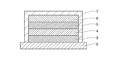
先ず、本発明の薄膜を適用する薄膜固体二次電池の構造を図1〜図3を参照して説明する。
なお、図1〜図3は、本発明による構造の異なる薄膜固体二次電池における積層構造を示す断面模式図である。
図1に示す薄膜固体二次電池の構造は、基板1上に正極集電体層2、正極活物質層3、固体電解質層4、負極活物質層5、負極集電体層6を順に形成した積層構造、あるいは、図2に示す薄膜固体二次電池は、基板1上に上記各層を図1の薄膜固体二次電池の場合と逆の順で形成した積層構造を有している。
なお、薄膜固体二次電池は、大気中の水分によって性能の劣化を生じるため、保護膜または保護フィルム7を設けることで、耐久性向上が図られている。
[Structure of thin-film solid secondary battery]
First, the structure of a thin film solid secondary battery to which the thin film of the present invention is applied will be described with reference to FIGS.
1 to 3 are schematic cross-sectional views showing a laminated structure in a thin film solid secondary battery having a different structure according to the present invention.
The thin film solid secondary battery shown in FIG. 1 has a structure in which a positive electrode
In addition, since a thin film solid secondary battery deteriorates in performance due to moisture in the atmosphere, durability is improved by providing a protective film or a
また、図1において、正極集電体層2を板状、または箔状にすれば、基板1が不要となり、図3に示すような図1、2の薄膜固体二次電池とは異なる基板を必要としない構造の薄膜固体二次電池とすることも可能である。
以下、薄膜固体二次電池の各要素について詳細に説明する。
Further, in FIG. 1, if the positive electrode
Hereinafter, each element of the thin film solid secondary battery will be described in detail.
(a)基板
使用する基板は、耐熱性基板がよく、中でもソーダライムガラス、無アルカリガラス、石英ガラス等のガラス基板、あるいはアルミナ(Al2O3)等のセラミック基板が好ましい。場合によっては、ポリイミド(PI)、ポリアミド等の耐熱性樹脂基板(プラスチックフィルム)を用いることもできる。
(A) Substrate The substrate to be used is preferably a heat-resistant substrate, and among them, a glass substrate such as soda lime glass, non-alkali glass or quartz glass, or a ceramic substrate such as alumina (Al 2 O 3 ) is preferable. In some cases, a heat-resistant resin substrate (plastic film) such as polyimide (PI) or polyamide can be used.
(b)集電体層(正極集電体層、負極集電体層)
正極集電体層2、負極集電体層6の材料としては、Cu、Mg、Ti、Fe、Co、Ni、V、Zn、Al、Ge、In、Au、Pt、Ag、Pd等、または、これらのいずれかを含む合金(例えばステンレススチール)から適宜選択して用いることができる。
上記材料は、スパッタリング法、蒸着法、メッキ法、塗布法等の既存の成膜方法を用いて基板1上に形成した薄膜として用いてもよいし、図3の薄膜固体二次電池のように、上記材料自体を板状、箔状にして用いることも可能である。
(B) Current collector layer (positive electrode current collector layer, negative electrode current collector layer)
Examples of materials for the positive electrode
The above material may be used as a thin film formed on the
(c)正極活物質層
正極活物質層3を形成する物質は、リチウムイオンを離脱、吸着させ易く、多くのリチウムイオンを離脱、吸蔵させることが可能な物質であればよく、リチウム−コバルト酸化物(LiCoO2[コバルト酸リチウム]、LiCo2O4等)(LCOと呼ばれる。)、リチウム−ニッケル酸化物(LiNiO2[ニッケル酸リチウム]、LiNi2O4等)(LNOと呼ばれる。)、リチウム−マンガン酸化物(LiMnO2[マンガン酸リチウム]、LiMn2O4、Li2Mn2O4等)(LMOと呼ばれる。)、リチウム−マンガン−コバルト酸化物(LiMnCoO4、Li2MnCoO4等)、リチウム−ニッケル−マンガン−コバルト酸化物(Li(Ni-Mn-Co)O2、LiNi1/3Mn1/3Co1/3O2等)(NMCまたはNCMと呼ばれる。)、リチウム−ニッケル−コバルト−アルミニウム酸化物(Li(Ni-Co-Al)O2)(NCAと呼ばれる。)、リチウム−チタン酸化物(Li4Ti5O12、LiTi2O4等)(LTOと呼ばれる。)、その他遷移金属を含むリチウム酸化物(Li2CuO2、LiCuO2、LiVO2、LiV2O4、LiCrO2、LiFeO2、LiTiO2、LiScO2、LiYO2、LiMnCrO4、LiNiVO4、LiCoVO4等)、各種遷移金属を含むリチウムリン酸塩(LiFePO4[リン酸鉄リチウム]、LiCuPO4、LiNiPO4、LiCoPO4、LiMnPO4、Li2NiPO4F、Li2CoPO4F、Li2MnPO4F、Li2FePO4F、LiVOPO4、Li3V2(PO4)3等)、各種遷移金属を含むリチウムケイ酸塩(Li2MnSiO4、Li2FeSiO4、Li2CoSiO4、Li2NiSiO4等)、各種遷移金属の硫化物(TiS2、MoS2、FeS、FeS2、CuS、Ni3S2)、各種遷移金属の酸化物(Bi2O3、Bi2Pb2O5、CuO、V2O5、V6O13、Nb2O5等)等を使用することができる。また、これらを混合して用いても良い。
(C) Positive electrode active material layer The material forming the positive electrode
ここで、正極活物質と負極活物質には明確な区別はなく、2種類の化合物の充放電電位を比較して貴な電位のものを正極活物質に、卑な電位のものを負極活物質に用いれば良い。
上記多くの正極活物質の中では、層状系材料としてのコバルト酸リチウム(LiCoO2)、ニッケル酸リチウム(LiNiO2)、リチウム−ニッケル−マンガン−コバルト酸化物(LiNi1/3Mn1/3Co1/3O2)、スピネル系材料としてのリチウム−マンガン酸化物(LiMn2O4)、オリビン系材料としてのリン酸鉄リチウム(LiFePO4)等が好適であり、一般的に用いられている。
正極活物質層3の膜厚は、薄型化という観点からするとできるだけ薄いことが望ましいが、充放電容量の確保を考えると、0.05〜5μm程度が適当である。
Here, there is no clear distinction between the positive electrode active material and the negative electrode active material, the charge / discharge potentials of the two types of compounds are compared, the positive potential is the positive electrode active material, and the base potential is the negative electrode active material. Can be used.
Among the many positive electrode active materials described above, lithium cobaltate (LiCoO 2 ), lithium nickelate (LiNiO 2 ), and lithium-nickel-manganese-cobalt oxide (LiNi 1/3 Mn 1/3 Co) as layered materials 1/3 O 2 ), lithium-manganese oxide (LiMn 2 O 4 ) as a spinel-based material, lithium iron phosphate (LiFePO 4 ) as an olivine-based material are suitable and generally used .
The thickness of the positive electrode
(d)負極活物質層
上述のように、負極活物質と正極活物質には明確な区別はなく、負極活物質層5を形成する物質は、リチウムイオンを吸着、離脱させ易く、多くのリチウムイオンを吸蔵、離脱させることが可能な物質であればよく、例えば、リチウム−チタン酸化物(Li4Ti5O12、LiTi2O4等)、リチウム−チタン−ニオブ酸化物(Li4(Ti2Nb3)O12等)、各種金属酸化物(Nb2O5、V2O5、NiO、In2O3、SnO2、ZnO、TiO2等)、各種単体元素(Si、Ge、Li、Mg、Al等)、各種シリコン合金(Si−Mn、Si−Co、Si−Ni等)、マグネシウム−リチウム合金(Mg−Li)、アルミニウム−リチウム合金(Al−Li系;AlLi等)、インジウム−リチウム合金(In−Li系;In2Li3等)、黒鉛(天然黒鉛、人造黒鉛等)等を使用することができる。また、これらを混合して用いても良い。
上記多くの負極活物質の中で、金属リチウム(Li)、各種リチウム合金(例えばAlLi、In2Li3等)、黒鉛、チタン酸リチウム(Li4Ti5O12)等が一般的に用いられるが、高容量化という観点からすると、金属リチウム(Li)、または各種リチウム合金が好ましく、これらはシート状や箔状として負極活物質層に適用することができる。
負極活物質層5の膜厚は、薄型化という観点からするとできるだけ薄いことが望ましいが、充放電容量の確保を考えると、0.05〜5μm程度が適当である。
(D) Negative electrode active material layer As described above, there is no clear distinction between the negative electrode active material and the positive electrode active material, and the material forming the negative electrode
Among the many negative electrode active materials, metallic lithium (Li), various lithium alloys (eg, AlLi, In 2 Li 3, etc.), graphite, lithium titanate (Li 4 Ti 5 O 12 ), etc. are generally used. However, from the viewpoint of increasing the capacity, metallic lithium (Li) or various lithium alloys are preferable, and these can be applied to the negative electrode active material layer as a sheet or foil.
The thickness of the negative electrode
(e)固体電解質層
固体電解質層4を形成する物質は、リチウムイオンの高いイオン伝導性を有する物質を用いることが必要で、酸化物系固体電解質としての、リン酸リチウム(Li3PO4)、リン酸リチウムに窒素を添加したLi3PO4NX(LiPONと呼ばれる。)、LiBO2NX、LiNbO3、LiTaO3、Li2SiO3、Li4SiO4−Li3PO4、Li4SiO4−Li3VO4、Li2O−B2O3−P2O5、Li2O−SiO2、Li2O−B2O3−ZnO、Li1+XAlXTi2−X(PO4)3(0≦X≦1)(LATPまたはLTAPと呼ばれる。)、Li1+XAlXGe2−X(PO4)3(0≦X≦1;具体的には、Li1.5Al0.5Ge1.5(PO4)3)(LAGPと呼ばれる。)、LiTi2(PO4)3、Li3XLa2/3−XTiO3(0≦X≦2/3;具体的には、Li0.33La0.56TiO3、Li0.5La0.5TiO3等)(LLTまたはLLTOと呼ばれる。)、Li5La3Ta2O12、Li7La3Zr2O12(LLZまたはLLZOと呼ばれる。)、Li6BaLa2Ta2O12、Li3.6Si0.6P0.4O4等、硫化物系固体電解質としての、Li2S−SiS2、LiI−Li2S−SiS2、LiI−Li2S−P2S5、LiI−Li2S−B2S3、Li3PO4−Li2S−Si2S、Li3PO4−Li2S−SiS2、LiPO4−Li2S−SiS、LiI−Li2S−P2O5、LiI−Li3PO4−P2S5、Li2S−P2S5等、あるいは、LiI−LiI−Al2O3、Li3N、Li3N−LiI−LiOH等を用いることができる。
(E) Solid electrolyte layer The substance forming the
さらに、リチウムイオン伝導性の観点から選択すると、酸化物系固体電解質よりも硫化物系固体電解質が好ましいが、一方で、硫化物系固体電解質は水分と反応して有毒な硫化水素ガスを発生するという問題がある。
したがって、リチウムイオン電池の製造工程の作業性、及び製品としてのリチウムイオン電池の安全性の観点からすると、酸化物系固体電解質の方が、硫化物系固体電解質よりも好ましい。
Furthermore, from the viewpoint of lithium ion conductivity, a sulfide-based solid electrolyte is preferable to an oxide-based solid electrolyte. On the other hand, a sulfide-based solid electrolyte reacts with moisture to generate toxic hydrogen sulfide gas. There is a problem.
Therefore, from the viewpoint of the workability of the manufacturing process of the lithium ion battery and the safety of the lithium ion battery as a product, the oxide solid electrolyte is preferable to the sulfide solid electrolyte.
この酸化物系固体電解質の中では、上記LATP、LLT、LLZ等が比較的高いリチウムイオン伝導性を有する(LATP:1×10⁴S/cm[25℃]、LLT:1×104S/cm[25℃]、LLZ:4×104S/cm[25℃])ため好ましい。ただし、負極活物質に金属リチウムやリチウム合金を適用する場合には、酸化チタン(TiO2)を構成成分として含むLATPやLLTは、金属リチウムやリチウム合金と固体電解質の界面でTi4+がTi3+に還元されてリチウムイオン伝導性が大幅に劣化するため使用することができない。
また、金属リチウムやリチウム合金を負極活物質に用いる場合には、上記劣化の生じないLLZが好適である。
固体電解質層4の膜厚は、薄型化やリチウムイオンの移動距離を短くするという観点からできるだけ薄いことが望ましいが、薄すぎると固体電解質層にピンホ−ルが発生し易くなるため、その防止の観点からすると、0.05〜1μm程度が好ましい。
Among the oxide-based solid electrolytes, the LATP, LLT, LLZ, and the like have relatively high lithium ion conductivity (LATP: 1 × 10 4 S / cm [25 ° C.], LLT: 1 × 10 4 S / cm [25 ° C.], LLZ: 4 × 10 4 S / cm [25 ° C.]). However, when metal lithium or a lithium alloy is applied to the negative electrode active material, LATP or LLT containing titanium oxide (TiO 2 ) as a constituent component is Ti 4+ is Ti 3+ at the interface between the metal lithium or lithium alloy and the solid electrolyte. It cannot be used because it is reduced to lithium ion conductivity and deteriorates significantly.
In addition, when metal lithium or a lithium alloy is used for the negative electrode active material, LLZ that does not cause the above-described deterioration is preferable.
The thickness of the
[塗布法で形成した活物質層や固体電解質層の構造]
次に、塗布法を用いて形成した薄膜である活物質層(正極、負極)や固体電解質層の構造を説明する。
例えば、スパッタリング法等の気相成長法を用いて金属酸化物を主成分とする活物質層(正極、負極)や固体電解質層を形成した場合、通常、金属酸化物の結晶粒が粒界を介して配列した膜構造である多結晶の膜構造(または緻密なアモルファス膜構造)が形成され、膜構造において金属酸化物微粒子はほとんど観察されない。
また、有機金属化合物を主成分とする(正極、負極)活物質層形成用塗布液や固体電解質層形成用塗布液を塗布、乾燥、無機化する塗布法で形成した活物質層(正極、負極)や固体電解質層では、通常、金属酸化物微粒子同士が結合した膜構造を有しており、金属酸化物微粒子の粒子径や金属酸化物微粒子間に存在する空隙の大きさは、無機化条件などで異なるが、少なからず開空隙(オープンポア)を有する金属酸化物微粒子で構成される活物質層(正極、負極)や固体電解質層となることが判っている。
[Structure of active material layer and solid electrolyte layer formed by coating method]
Next, the structure of the active material layer (positive electrode, negative electrode) and solid electrolyte layer, which are thin films formed using a coating method, will be described.
For example, when an active material layer (positive electrode, negative electrode) or solid electrolyte layer mainly composed of a metal oxide is formed using a vapor phase growth method such as a sputtering method, the crystal grains of the metal oxide usually have grain boundaries. A polycrystalline film structure (or a dense amorphous film structure), which is a film structure arranged through the film structure, is formed, and metal oxide fine particles are hardly observed in the film structure.
In addition, an active material layer (positive electrode, negative electrode) formed by a coating method in which an active material layer-forming coating solution or a solid electrolyte layer forming coating solution containing an organometallic compound as a main component (solid, positive electrode, negative electrode) is applied. ) And the solid electrolyte layer usually has a film structure in which metal oxide fine particles are bonded to each other. The particle size of the metal oxide fine particles and the size of the voids existing between the metal oxide fine particles are determined according to the mineralization conditions However, it is known that the active material layer (positive electrode, negative electrode) or solid electrolyte layer composed of metal oxide fine particles having open pores (open pores).
そして、この塗布法で形成された金属酸化物微粒子同士が結合した活物質層(正極、負極)や固体電解質層においては、活物質層(正極、負極)や固体電解質層が導電性(電子伝導やイオン伝導)を有する場合には、その導電機構が金属酸化物微粒子の接触部分(結合部分)を介在するものであることから、金属酸化物微粒子同士が微小面積で接触して導電性を発現していると考えられる。
なお、固体二次電池では、通常の液体電解質層を用いる二次電池と異なり、活物質層(正極、負極)中活物質成分間に固体電解質層成分を介在させて(リチウムイオンの)イオン伝導を促進させる必要があり、したがって、上記金属酸化物微粒子同士の導電性に加え、この固体電解質層成分の(リチウムイオンの)イオン伝導の観点からも、活物質層の金属酸化物微粒子間に存在する空隙の大きさを適宜制御する必要がある。
In the active material layer (positive electrode, negative electrode) or solid electrolyte layer in which the metal oxide fine particles formed by this coating method are bonded, the active material layer (positive electrode, negative electrode) or solid electrolyte layer is conductive (electron conduction). Or ionic conduction), the metal oxide fine particles come into contact with each other in a very small area because the conductive mechanism intervenes the contact portion (bonding portion) of the metal oxide fine particles, and the conductivity is expressed. it seems to do.
In addition, unlike a secondary battery using a normal liquid electrolyte layer, the solid secondary battery has a solid electrolyte layer component interposed between the active material components in the active material layer (positive electrode and negative electrode) and conducts ions (of lithium ions). Therefore, in addition to the conductivity between the metal oxide fine particles, the solid electrolyte layer component (lithium ion) ion conduction also exists between the metal oxide fine particles in the active material layer. It is necessary to appropriately control the size of the gap to be generated.
このような塗布法を用いて形成された薄膜の活物質層(正極、負極)や固体電解質層では、活物質層の金属酸化物微粒子の充填状態、充填密度を制御して、開空隙(オープンポア)の大きさや数を制御し、活物質層の金属酸化物微粒子同士の接触状態や固体電解質成分の活物質層内への介在(染み込み)状態を制御することが望ましく、そのためには、塗布法における無機化工程の昇温過程において、水蒸気含有量、すなわち露点温度を制御した酸素含有雰囲気を適用することが望ましい。 In a thin-film active material layer (positive electrode, negative electrode) or solid electrolyte layer formed by using such a coating method, the filling state and packing density of the metal oxide fine particles in the active material layer are controlled, and an open gap (open) It is desirable to control the size and number of pores, and to control the state of contact between the metal oxide fine particles in the active material layer and the state of penetration (soaking) of the solid electrolyte component into the active material layer. It is desirable to apply an oxygen-containing atmosphere in which the water vapor content, that is, the dew point temperature is controlled, in the temperature raising process of the mineralization step in the method.
このような緻密な金属酸化物微粒子を主成分とする無機薄膜の形成機構については、いまだ明らかとはいえず、後でも詳細に説明(段落[0132]から[0133]参照)するが、要は酸素含有雰囲気中に水蒸気が存在すると、有機金属化合物等が熱分解・燃焼して生じる無機化による金属酸化物の結晶化並びに結晶成長が、水蒸気で促進され、熱分解・燃焼を行なう無機化工程での初期段階で金属酸化物微粒子同士を固着して動けなくしてしまうため、金属酸化物微粒子の緻密化が生じにくくなるためと推測される。 The formation mechanism of the inorganic thin film mainly composed of such fine metal oxide fine particles has not been clarified yet and will be described in detail later (see paragraphs [0132] to [0133]). When water vapor is present in an oxygen-containing atmosphere, crystallization and crystal growth of metal oxides due to mineralization caused by pyrolysis and combustion of organometallic compounds, etc. are promoted by water vapor, and an inorganicization process in which pyrolysis and combustion are performed. It is presumed that the metal oxide fine particles adhere to each other at the initial stage and become immovable, so that the metal oxide fine particles are hardly densified.
一方、塗布法による活物質層(正極、負極)や固体電解質層の無機化工程において、水蒸気含有量の少ない、すなわち露点温度が低い酸素含有雰囲気を適用すれば、活物質層(正極、負極)や固体電解質層の金属酸化物の種類や組成にもよるが、例えば、活物質層(正極、負極)や固体電解質層における金属酸化物微粒子の充填密度を、場合によっては金属酸化物の真比重の70〜90%程度まで高めることが可能であり、また逆に水蒸気を多く含む酸素含有雰囲気を適用した場合には、真比重の40〜70%程度に留まることがある。要するに、無機化工程における酸素含有雰囲気の露点温度は、適用する活物質層(正極、負極)や固体電解質層に応じ適宜最適となるように設定すればよい。 On the other hand, if an oxygen-containing atmosphere with a low water vapor content, that is, a low dew point temperature is applied in the mineralization step of the active material layer (positive electrode, negative electrode) or solid electrolyte layer by a coating method, the active material layer (positive electrode, negative electrode) Depending on the type and composition of the metal oxide of the solid electrolyte layer and the solid oxide layer, for example, the packing density of the metal oxide fine particles in the active material layer (positive electrode, negative electrode) or solid electrolyte layer may be changed depending on the true specific gravity of the metal oxide. In contrast, when an oxygen-containing atmosphere containing a large amount of water vapor is applied, it may remain at about 40 to 70% of the true specific gravity. In short, the dew point temperature of the oxygen-containing atmosphere in the mineralization step may be set to be optimal as appropriate according to the active material layer (positive electrode, negative electrode) or solid electrolyte layer to be applied.
[(正極、負極)活物質層形成用塗布液、固体電解質層形成用塗布液]
本発明では、活物質層(正極、負極)や固体電解質層の形成に、(正極、負極)活物質層形成用塗布液や固体電解質層形成用塗布液を用いており、以下これら各種塗布液について説明する。
[(Positive electrode, negative electrode) active material layer forming coating solution, solid electrolyte layer forming coating solution]
In the present invention, the active material layer (positive electrode, negative electrode) and the solid electrolyte layer are formed by using the (positive electrode, negative electrode) active material layer forming coating solution or the solid electrolyte layer forming coating solution. Will be described.
(a)塗布液の主成分としての有機金属化合物
(1)正極活物質層形成用塗布液
本発明で用いられる正極活物質層形成用塗布液について詳細に説明する。
本発明では、マンガン、コバルト、ニッケル、鉄のうちのいずれか一種以上の遷移金属の有機金属化合物、及び有機リチウム化合物を主成分とする正極活物質層形成用塗布液を用いて、マンガン、コバルト、ニッケル、鉄のうちのいずれか一種以上の遷移金属を含むリチウム複合酸化物を主成分とする微粒子膜(無機薄膜)からなる正極活物質層を形成している。
(A) Organometallic compound as main component of coating liquid (1) Coating liquid for forming positive electrode active material layer The coating liquid for forming a positive electrode active material layer used in the present invention will be described in detail.
In the present invention, using a coating liquid for forming a positive electrode active material layer containing, as a main component, an organic metal compound of one or more transition metals of manganese, cobalt, nickel, and iron, and an organic lithium compound, manganese, cobalt A positive electrode active material layer made of a fine particle film (inorganic thin film) mainly composed of a lithium composite oxide containing one or more transition metals of nickel, iron, and nickel is formed.
まず、本発明で用いる有機リチウム化合物について、以下に説明する。
有機リチウム化合物は、無機化により酸化リチウム(Li2O)となり、この酸化リチウムは、塗布法で得られるリチウム複合酸化物の主成分を構成する。
本発明で用いることができる有機リチウム化合物としては、例えば、アセチルアセトンリチウム(正式名称:リチウム(I)−2,4−ペンタンジオネート[Li(C5H7O2)]、蟻酸リチウム(I)[Li(HCOO)]、リチウムアルコキシドとしてのリチウム(I)エトキシド[Li(C2H5O)]、リチウム(I)−tert−ブトキシド[Li(C4H9O)]、リチウム(I)イソプロポキシド[Li(C3H7O)]等が挙げられるが、基本的には、溶剤に溶解し、無機化時において塩素ガスや窒素酸化物ガスなどの有害ガスが発生せずに酸化物に分解する有機リチウム化合物であれば良い。これらの中でもアセチルアセトンリチウムは有機溶剤への溶解性が高く、熱分解・燃焼(酸化)して酸化物となり易いため好ましい。
First, the organolithium compound used in the present invention will be described below.
The organic lithium compound becomes lithium oxide (Li 2 O) by mineralization, and this lithium oxide constitutes the main component of the lithium composite oxide obtained by a coating method.
Examples of the organic lithium compound that can be used in the present invention include lithium acetylacetone (formal name: lithium (I) -2,4-pentanedionate [Li (C 5 H 7 O 2 )], lithium formate (I). [Li (HCOO)], lithium (I) ethoxide as lithium alkoxide [Li (C 2 H 5 O)], lithium (I) -tert-butoxide [Li (C 4 H 9 O)], lithium (I) Isopropoxide [Li (C 3 H 7 O)] and the like can be mentioned. Basically, it is dissolved in a solvent and oxidized without generating harmful gases such as chlorine gas and nitrogen oxide gas during mineralization. Of these, lithium acetylacetone is highly soluble in organic solvents, and decomposes and burns (oxidizes) to become an oxide. Fried preferred.
次に、本発明で用いるマンガン、コバルト、ニッケル、鉄のそれぞれの有機金属化合物について、以下に説明する。
有機マンガン化合物は、無機化により酸化マンガン(MnO、Mn2O3、MnO2等)となり、この酸化マンガンは、塗布法で得られるリチウム複合酸化物の主成分を構成する。
本発明で用いることができる有機マンガン化合物としては、例えば、マンガンアセチルアセトン錯体としてのアセチルアセトンマンガン{(正式名称:マンガン(II)−2,4−ペンタンジオネート)[Mn(C5H7O2)2]、(正式名称:マンガン(III)−2,4−ペンタンジオネート)[Mn(C5H7O2)3]}等や、有機酸マンガンとしての酢酸マンガン(II)[Mn(CH3COO)2]等が挙げられるが、基本的には、溶剤に溶解し、無機化時において塩素ガスや窒素酸化物ガスなどの有害ガスが発生せずに酸化物に分解する有機マンガン化合物であれば良い。
Next, the organometallic compounds of manganese, cobalt, nickel, and iron used in the present invention will be described below.
The organic manganese compound becomes manganese oxide (MnO, Mn 2 O 3 , MnO 2, etc.) by mineralization, and this manganese oxide constitutes the main component of the lithium composite oxide obtained by the coating method.
As an organic manganese compound that can be used in the present invention, for example, acetylacetone manganese {(formal name: manganese (II) -2,4-pentanedionate) [Mn (C 5 H 7 O 2 )] as a manganese acetylacetone complex. 2 ], (formal name: manganese (III) -2,4-pentanedionate) [Mn (C 5 H 7 O 2 ) 3 ]} and the like, and manganese acetate (II) [Mn (CH 3 COO) 2 ] and the like. Basically, it is an organic manganese compound that dissolves in a solvent and decomposes into an oxide without generating harmful gases such as chlorine gas and nitrogen oxide gas during mineralization. I just need it.
有機鉄化合物は、無機化により酸化鉄(FeO、Fe2O3等)となり、この酸化鉄は、塗布法で得られるリチウム複合酸化物の主成分を構成する。
本発明で用いることができる有機鉄化合物としては、例えば、鉄アセチルアセトン錯体としてのアセチルアセトン鉄(正式名称:鉄(III)−2,4−ペンタンジオネート)[Fe(C5H7O2)3]等、鉄アルコキシドとしての鉄(III)エトキシド[Fe(C2H5O)3]等、有機酸鉄としての酢酸鉄(III)[Fe(CH3COO)3]等が挙げられるが、基本的には、溶剤に溶解し、無機化時において塩素ガスや窒素酸化物ガスなどの有害ガスが発生せずに酸化物に分解する有機鉄化合物であれば良い。
The organic iron compound becomes iron oxide (FeO, Fe 2 O 3 or the like) by mineralization, and this iron oxide constitutes the main component of the lithium composite oxide obtained by a coating method.
As an organic iron compound that can be used in the present invention, for example, acetylacetone iron (formal name: iron (III) -2,4-pentandionate) [Fe (C 5 H 7 O 2 ) 3 as an iron acetylacetone complex] 3 , Etc., iron (III) ethoxide as an iron alkoxide [Fe (C 2 H 5 O) 3 ], etc., iron acetate (III) as an organic acid iron [Fe (CH 3 COO) 3 ], etc. Basically, it may be an organic iron compound that dissolves in a solvent and decomposes into an oxide without generating harmful gases such as chlorine gas and nitrogen oxide gas during mineralization.
有機コバルト化合物は、無機化により酸化コバルト(CoO、Co2O3等)となり、この酸化コバルトは、塗布法で得られるリチウム複合酸化物の主成分を構成する。
本発明で用いることができる有機コバルト化合物としては、例えば、コバルトアセチルアセトン錯体としてのアセチルアセトンコバルト{(正式名称:コバルト(II)−2,4−ペンタンジオネート)[Co(C5H7O2)2]、(正式名称:コバルト(III)−2,4−ペンタンジオネート)[Co(C5H7O2)3]}等や、有機酸コバルトとしての蟻酸コバルト(II)[Co(COOH)2・2H2O]、酢酸コバルト(II)[Co(CH3COO)2]等が挙げられるが、基本的には、溶剤に溶解し、無機化時において塩素ガスや窒素酸化物ガスなどの有害ガスが発生せずに酸化物に分解する有機コバルト化合物であれば良い。
The organic cobalt compound becomes cobalt oxide (CoO, Co 2 O 3 or the like) by mineralization, and this cobalt oxide constitutes the main component of the lithium composite oxide obtained by a coating method.
As an organic cobalt compound that can be used in the present invention, for example, acetylacetone cobalt as a cobalt acetylacetone complex {(formal name: cobalt (II) -2,4-pentanedionate) [Co (C 5 H 7 O 2 )] 2 ], (formal name: cobalt (III) -2,4-pentanedionate) [Co (C 5 H 7 O 2 ) 3 ]} and the like, and cobalt formate (II) as an organic acid cobalt [Co (COOH ) 2 · 2H 2 O], cobalt acetate (II) [Co (CH 3 COO) 2 ], etc., are basically dissolved in a solvent and chlorine gas, nitrogen oxide gas, etc. at the time of mineralization Any organic cobalt compound that decomposes into an oxide without generating any harmful gas may be used.
有機ニッケル化合物は、無機化により酸化ニッケル(NiO、Ni2O3等)となり、この酸化ニッケルは、塗布法で得られるリチウム複合酸化物の主成分を構成する。
本発明で用いることができる有機ニッケル化合物としては、例えば、ニッケルアセチルアセトン錯体としてのアセチルアセトンニッケル(正式名称:ニッケル(II)−2,4−ペンタンジオネート)[Ni(C5H7O2)2]等や、有機酸ニッケルとしての蟻酸ニッケル(II)[Ni(HCOO)2・2H2O]、酢酸ニッケル(II)[Ni(CH3COO)2]等が挙げられるが、基本的には、溶剤に溶解し、無機化時において塩素ガスや窒素酸化物ガスなどの有害ガスが発生せずに酸化物に分解する有機ニッケル化合物であれば良い。
The organic nickel compound becomes nickel oxide (NiO, Ni 2 O 3 or the like) by mineralization, and this nickel oxide constitutes the main component of the lithium composite oxide obtained by a coating method.
Examples of the organic nickel compound that can be used in the present invention include acetylacetone nickel (formal name: nickel (II) -2,4-pentandionate) [Ni (C 5 H 7 O 2 ) 2 as a nickel acetylacetone complex. Etc., and nickel formate (II) [Ni (HCOO) 2 · 2H 2 O], nickel acetate (II) [Ni (CH 3 COO) 2 ], etc. as organic acid nickel, Any organic nickel compound can be used as long as it is dissolved in a solvent and decomposes into an oxide without generating harmful gases such as chlorine gas and nitrogen oxide gas during mineralization.
ここで、前述のリチウム複合酸化物が、LiMPO4、Li2MSiO4(M:マンガン、コバルト、ニッケル、鉄のうちのいずれか一種以上の遷移金属)の場合は、リンとケイ素の有機金属化合物(有機リン化合物、有機ケイ素化合物)を用いるため、それぞれについて以下に説明する。 Here, in the case where the lithium composite oxide is LiMPO 4 or Li 2 MSiO 4 (M: one or more transition metals of manganese, cobalt, nickel, and iron), an organometallic compound of phosphorus and silicon Since (organic phosphorus compound, organosilicon compound) are used, each will be described below.
有機リン化合物は、無機化により酸化リン(P2O5等)となり、この酸化リンは、塗布法で得られるLiMPO4(M:マンガン、コバルト、ニッケル、鉄のうちのいずれか一種以上の遷移金属)の主成分を構成する。
有機リン化合物としては、例えば、トリエチルフォスフェイト[PO(C2H5O)3]、トリブチルフォスフェイト[PO(C4H9O)3]、トリペンチルフォスフェイト(別名:トリアミルフォスフェイト)[PO(C5H11O)3]、ビス(2−エチルヘキシル)フォスフェイト[(C4H9CH(C2H5)CH2)2HPO4]等が挙げられるが、基本的には、溶剤に溶解し、無機化時において塩素ガスや窒素酸化物ガスなどの有害ガスが発生せずに酸化物に分解する有機リン化合物であれば良い。
これらの中でもトリペンチルフォスフェイトやビス(2−エチルヘキシル)フォスフェイトは、有機溶剤への溶解性が高く、蒸気圧が低いため乾燥工程における成分揮発が抑制できるため好ましい。
The organic phosphorus compound becomes phosphorus oxide (P 2 O 5 or the like) by mineralization, and this phosphorus oxide is a transition of one or more of LiMPO 4 (M: manganese, cobalt, nickel, iron) obtained by a coating method. The main component of (metal).
Examples of the organic phosphorus compound include triethyl phosphate [PO (C 2 H 5 O) 3 ], tributyl phosphate [PO (C 4 H 9 O) 3 ], and tripentyl phosphate (also known as triamyl phosphate). [PO (C 5 H 11 O) 3 ], bis (2-ethylhexyl) phosphate [(C 4 H 9 CH (C 2 H 5 ) CH 2 ) 2 HPO 4 ] and the like are basically mentioned. Any organic phosphorus compound that dissolves in a solvent and decomposes into an oxide without generating harmful gas such as chlorine gas or nitrogen oxide gas during mineralization may be used.
Among these, tripentyl phosphate and bis (2-ethylhexyl) phosphate are preferable because they have high solubility in organic solvents and low vapor pressure, so that component volatilization in the drying process can be suppressed.
有機ケイ素化合物は、無機化により酸化ケイ素(SiO2等)となり、この酸化ケイ素は、塗布法で得られるLi2MSiO4(M:マンガン、コバルト、ニッケル、鉄のうちのいずれか一種以上の遷移金属)の主成分を構成する。
有機ケイ素化合物としては、多くのタイプの有機化合物が存在するが、例えば、シリコンアルコキシドとしてのシリコン(IV)テトラメトキシド[Si(CH3O)4]、シリコン(IV)テトラエトキシド[Si(C2H5O)4]、シリコン(IV)−tert−ブトキシド[Si(C4H9O)4]、シリコン(IV)テトラ−n−ブトキシド[Si(C4H9O)4]、シリコン(IV)テトライソプロポキシド[Si(C3H7O)4]等が挙げられるが、基本的には、溶剤に溶解し、無機化時において塩素ガスや窒素酸化物ガスなどの有害ガスが発生せずに酸化物に分解する有機ケイ素化合物であれば良い。
The organosilicon compound becomes silicon oxide (SiO 2 or the like) by mineralization, and this silicon oxide is Li 2 MSiO 4 (M: transition of any one or more of manganese, cobalt, nickel, and iron obtained by a coating method) The main component of (metal).
There are many types of organic silicon compounds. For example, silicon (IV) tetramethoxide [Si (CH 3 O) 4 ] or silicon (IV) tetraethoxide [Si ( C 2 H 5 O) 4] , silicon (IV)-tert-butoxide [Si (C 4 H 9 O ) 4], silicon (IV) tetra -n- butoxide [Si (C 4 H 9 O ) 4], Silicon (IV) tetraisopropoxide [Si (C 3 H 7 O) 4 ] and the like can be mentioned, but basically, it is dissolved in a solvent and harmful gases such as chlorine gas and nitrogen oxide gas at the time of mineralization Any organic silicon compound that can be decomposed into an oxide without generation of water may be used.
(2)負極活物質層形成用塗布液
次に、本発明で用いられる負極活物質層形成用塗布液について詳細に説明する。
本発明では、有機チタン化合物と有機リチウム化合物、または、ニオブ、インジウム、錫、亜鉛、チタンのうちのいずれか一種以上の金属の有機金属化合物を主成分とする負極活物質層形成用塗布液を用いて、リチウム−チタン酸化物、酸化ニオブ、酸化インジウム、酸化錫、酸化亜鉛、酸化チタンのうちのいずれか一種以上の酸化物を主成分とする微粒子膜(無機薄膜)からなる負極活物質層を形成している。
(2) Coating liquid for forming negative electrode active material layer Next, the coating liquid for forming negative electrode active material layer used in the present invention will be described in detail.
In the present invention, a coating liquid for forming a negative electrode active material layer containing, as a main component, an organotitanium compound and an organolithium compound, or an organometallic compound of one or more metals selected from niobium, indium, tin, zinc, and titanium A negative electrode active material layer comprising a fine particle film (inorganic thin film) containing as a main component any one or more of lithium-titanium oxide, niobium oxide, indium oxide, tin oxide, zinc oxide, and titanium oxide. Is forming.
本発明で用いる有機リチウム化合物は、正極活物質層形成用塗布液に用いた有機リチウム化合物と同一であり、無機化により酸化リチウム(Li2O)となり、この酸化リチウムは、塗布法で得られるリチウム−チタン酸化物(Li4Ti5O12)の主成分を構成する。 The organolithium compound used in the present invention is the same as the organolithium compound used in the coating liquid for forming the positive electrode active material layer, and becomes lithium oxide (Li 2 O) by mineralization. This lithium oxide is obtained by a coating method. It constitutes the main component of lithium-titanium oxide (Li 4 Ti 5 O 12 ).
次に、本発明で用いるチタン、ニオブ、インジウム、錫、亜鉛のそれぞれの有機金属化合物について、以下に説明する。
有機チタン化合物は、無機化により酸化チタン(TiO2等)となり、この酸化チタンは、塗布法で得られるリチウム−チタン酸化物(Li4Ti5O12)の主成分を構成し、また単独でも負極活物質層の主成分を構成できる。
有機チタン化合物としては、例えば、チタンアセチルアセトン錯体としてのアセチルアセトンチタン(正式名称:チタン(IV)ジ−n−ブトキシド ビス(2,4−ペンタンジオネート)[Ti(C4H9O)2(C5H7O2)2] )、チタニル(IV)アセチルアセトネート[(C5H7O2)4TiO]、チタン(IV)ジイソプロポキシド ビス(2,4−ペンタンジオネート)[Ti(C3H7O)2(C5H7O2)2]等や、チタンアルコキシドとしてのチタン(IV)テトラエトキシド[Ti(C2H5O)4]、チタン(IV)−tert−ブトキシド[Ti(C4H9O)4]、チタン(IV)テトラ−n−ブトキシド[Ti(C4H9O)4]、チタン(IV)テトライソプロポキシド[Ti(C3H7O)4]等が挙げられるが、基本的には、溶剤に溶解し、無機化時において塩素ガスや窒素酸化物ガスなどの有害ガスが発生せずに酸化物に分解する有機チタン化合物であれば良く、これらの中でも、アセチルアセトンチタン、チタン(IV)テトラ−n−ブトキシド、チタン(IV)テトライソプロポシドは、安価で入手し易いので好ましい。
Next, each organometallic compound of titanium, niobium, indium, tin, and zinc used in the present invention will be described below.
The organic titanium compound becomes titanium oxide (TiO 2 or the like) by mineralization, and this titanium oxide constitutes a main component of lithium-titanium oxide (Li 4 Ti 5 O 12 ) obtained by a coating method, or alone. The main component of a negative electrode active material layer can be comprised.
As an organic titanium compound, for example, acetylacetone titanium (formal name: titanium (IV) di-n-butoxide bis (2,4-pentanedionate) [Ti (C 4 H 9 O) 2 (C 5 H 7 O 2) 2] ), titanyl (IV) acetylacetonate [(C 5 H 7 O 2 ) 4 TiO], titanium (IV) diisopropoxide bis (2,4-pentanedionate) [Ti (C 3 H 7 O) 2 (C 5 H 7 O 2 ) 2 ] and the like, titanium (IV) tetraethoxide [Ti (C 2 H 5 O) 4 ] as titanium alkoxide, titanium (IV) -tert - butoxide [Ti (C 4 H 9 O ) 4], titanium (IV) tetra -n- butoxide [Ti (C 4 H 9 O ) 4], titanium (IV) tetra isopropoxide Kishido Although [Ti (C 3 H 7 O ) 4] , and the like, basically, dissolved in a solvent, an oxide without generating harmful gas such as chlorine gas or nitrogen oxide gas at the time of mineralization Any of these may be used as long as it is an organic titanium compound that decomposes into acetylacetone, among which titanium acetylacetone, titanium (IV) tetra-n-butoxide, and titanium (IV) tetraisoproposide are preferable because they are inexpensive and readily available.
有機ニオブ化合物は、無機化により酸化ニオブ(Nb2O5等)となり、この塗布法で得られる酸化ニオブは負極活物質層の主成分を構成する。
有機ニオブ化合物としては、例えば、ニオブアルコキシドとしてのニオブ(V)エトキシド[Nb(C2H5O)5]、ニオブ(V)−n−ブトキシド[Nb(C4H9O)5]等が挙げられるが、基本的には、溶剤に溶解し、無機化時において塩素ガスや窒素酸化物ガスなどの有害ガスが発生せずに酸化物に分解する有機ニオブ化合物であれば良い。
The organic niobium compound becomes niobium oxide (Nb 2 O 5 or the like) by mineralization, and niobium oxide obtained by this coating method constitutes the main component of the negative electrode active material layer.
Examples of the organic niobium compound include niobium (V) ethoxide [Nb (C 2 H 5 O) 5 ], niobium (V) -n-butoxide [Nb (C 4 H 9 O) 5 ] and the like as niobium alkoxide. Basically, any organic niobium compound that dissolves in a solvent and decomposes into an oxide without generating a harmful gas such as chlorine gas or nitrogen oxide gas at the time of mineralization may be used.
有機インジウム化合物は、無機化により酸化インジウム(In2O3)となり、この塗布法で得られる酸化インジウムは負極活物質層の主成分を構成する。
有機インジウム化合物は、例えば、アセチルアセトンインジウム(正式名称:トリス(アセチルアセトナト)インジウム(III))[In(C5H7O2)3]、2−エチルヘキサン酸インジウム(III)[In(C7H15COO2)3]、蟻酸インジウム(III)[In(HCOO)3]、酢酸インジウム(III)[In(CH3COO)3]、インジウムアルコキシドとしてのインジウム(III)メトキシエトキシド[In(CH3OC2H4O)3]等が挙げられるが、基本的には、溶剤に溶解し、無機化時において塩素ガスや窒素酸化物ガスなどの有害ガスが発生せずに酸化物に分解する有機インジウム化合物であれば良い。これらの中でもアセチルアセトンインジウムは有機溶剤への溶解性が高く、熱分解・燃焼(酸化)して酸化物となり易いため好ましい。
The organic indium compound becomes indium oxide (In 2 O 3 ) by mineralization, and indium oxide obtained by this coating method constitutes the main component of the negative electrode active material layer.
Examples of the organic indium compound include acetylacetone indium (formal name: tris (acetylacetonato) indium (III)) [In (C 5 H 7 O 2 ) 3 ], indium (III) 2-ethylhexanoate [In (C 7 H 15 COO 2 ) 3 ], indium formate (III) [In (HCOO) 3 ], indium (III) acetate [In (CH 3 COO) 3 ], indium (III) methoxyethoxide as indium alkoxide [In (CH 3 OC 2 H 4 O) 3 ], etc., are basically used, but it is dissolved in a solvent, and in the mineralization, no harmful gas such as chlorine gas or nitrogen oxide gas is generated and the oxide is formed. Any organic indium compound that decomposes may be used. Among these, indium acetylacetone is preferable because it has high solubility in organic solvents and is easily decomposed and burned (oxidized) to become an oxide.
有機錫化合物は、無機化により酸化錫(SnO2)となり、この塗布法で得られる酸化錫は負極活物質層の主成分を構成する。
有機錫化合物(化合物中の錫の価数は2価、4価にこだわらない)は、例えば、アセチルアセトン錫(正式名称:ジ−n−ブチル ビス(2,4−ペンタンジオナト)錫(IV))[Sn(C4H9)2(C5H7O2)2]、2−エチルヘキサン酸錫(II)(別名:オクチル酸錫(II))[Sn(C7H15COO2)2]、酢酸錫(II)[Sn(CH3COO)2]、酢酸錫(IV)[Sn(CH3COO)4]、ジ−n−ブチル錫(IV)ジアセテート[Sn(C4H9)2(CH3COO)2] 、蟻酸錫(II)[Sn(HCOO)2]、錫アルコキシドとしての錫(IV)−tert−ブトキシド[Sn(C4H9O)4]等が挙げられるが、基本的には、溶剤に溶解し、無機化時において塩素ガスや窒素酸化物ガスなどの有害ガスが発生せずに酸化物に分解する有機錫化合物であれば良い。これらの中でも、アセチルアセトン錫は、比較的安価で入手し易いので好ましい。
The organic tin compound becomes tin oxide (SnO 2 ) by mineralization, and tin oxide obtained by this coating method constitutes the main component of the negative electrode active material layer.
The organic tin compound (the valence of tin in the compound is not limited to bivalent and tetravalent) is, for example, acetylacetone tin (formal name: di-n-butyl bis (2,4-pentanedionato) tin (IV) ) [Sn (C 4 H 9 ) 2 (C 5 H 7 O 2 ) 2 ], tin (II) 2-ethylhexanoate (also known as tin (II) octylate) [Sn (C 7 H 15 COO 2 ) 2], tin acetate (II) [Sn (CH 3 COO) 2], tin acetate (IV) [Sn (CH 3 COO) 4], di -n- butyl tin (IV) diacetate [Sn (C 4 H 9 ) 2 (CH 3 COO) 2 ], tin (II) formate [Sn (HCOO) 2 ], tin (IV) -tert-butoxide [Sn (C 4 H 9 O) 4 ] as a tin alkoxide, and the like. Basically, however, it dissolves in the solvent and is added during mineralization. It may be a decomposed organic tin compound oxide without generating harmful gas such as chlorine gas or nitrogen oxide gas. Among these, acetylacetone tin is preferable because it is relatively inexpensive and easily available.
有機亜鉛化合物は、無機化により酸化亜鉛(ZnO)となり、この塗布法で得られる酸化亜鉛は負極活物質層の主成分を構成する。
有機亜鉛化合物は、例えば、亜鉛アセチルアセトン錯体としてのアセチルアセトン亜鉛(正式名称:亜鉛(II)−2,4−ペンタンジオネート)[Zn(C5H7O2)2]、亜鉛(II)−2,2,6,6−テトラメチル−3,5−ヘプタンジオネート[Zn(C11H19O2)2]、亜鉛アルコキシドとしての亜鉛(II)メトキシエトキシド[Zn(CH3OC2H4O)2]等が挙げられるが、基本的には、溶剤に溶解し、無機化時において塩素ガスや窒素酸化物ガスなどの有害ガスが発生せずに酸化物に分解する有機亜鉛化合物であれば良い。これらの中でも、アセチルアセトン亜鉛は、安価で入手し易いので好ましい。
The organic zinc compound becomes zinc oxide (ZnO) by mineralization, and zinc oxide obtained by this coating method constitutes the main component of the negative electrode active material layer.
The organic zinc compound is, for example, acetylacetone zinc (formal name: zinc (II) -2,4-pentanedionate) [Zn (C 5 H 7 O 2 ) 2 ], zinc (II) -2 as a zinc acetylacetone complex. , 2,6,6-tetramethyl-3,5-heptanedionate [Zn (C 11 H 19 O 2) 2], zinc as zinc alkoxide (II) methoxyethoxide [Zn (CH 3 OC 2 H 4 O) 2 ] and the like, but basically, an organic zinc compound that dissolves in a solvent and decomposes into an oxide without generating harmful gases such as chlorine gas and nitrogen oxide gas during mineralization. It ’s fine. Among these, zinc acetylacetone is preferable because it is inexpensive and easily available.
(3)固体電解質層形成用塗布液
本発明で用いられる固体電解質層形成用塗布液について詳細に説明する。
本発明では、有機リン化合物と有機リチウム化合物の有機金属化合物を主成分とする固体電解質層形成用塗布液、あるいは、有機ランタン化合物と有機リチウム化合物の有機金属化合物を主成分とする固体電解質層形成用塗布液を用いて、リンを含むリチウム複合酸化物、あるいは、ランタンを含むリチウム複合酸化物を主成分とする微粒子膜(無機薄膜)からなる固体電解質層を形成している。
(3) Solid Electrolyte Layer Forming Coating Liquid The solid electrolyte layer forming coating liquid used in the present invention will be described in detail.
In the present invention, a coating solution for forming a solid electrolyte layer mainly composed of an organometallic compound of an organophosphorus compound and an organolithium compound, or a solid electrolyte layer formed mainly of an organometallic compound of an organic lanthanum compound and an organolithium compound A solid electrolyte layer made of a fine particle film (inorganic thin film) containing, as a main component, a lithium composite oxide containing phosphorus or a lithium composite oxide containing lanthanum is formed by using the coating liquid.
本発明で用いる有機リチウム化合物は、正極活物質層形成用塗布液に用いた有機リチウム化合物と同一であり、無機化により酸化リチウム(Li2O)となり、この酸化リチウムは、塗布法で得られるリンを含むリチウム複合酸化物、あるいは、ランタンを含むリチウム複合酸化物の主成分を構成する。 The organolithium compound used in the present invention is the same as the organolithium compound used in the coating liquid for forming the positive electrode active material layer, and becomes lithium oxide (Li 2 O) by mineralization. This lithium oxide is obtained by a coating method. It constitutes a main component of a lithium composite oxide containing phosphorus or a lithium composite oxide containing lanthanum.
また上記有機リン化合物も、正極活物質層形成用塗布液に用いた有機リン化合物と同一であり、無機化により酸化リン(P2O5)となり、この酸化リンは、塗布法で得られるリンを含むリチウム複合酸化物の主成分を構成する。 The organic phosphorus compound is also the same as the organic phosphorus compound used in the coating liquid for forming the positive electrode active material layer, and is converted to phosphorus oxide (P 2 O 5 ) by mineralization. Constitutes the main component of the lithium composite oxide containing.
ここで、前述のリンを含むリチウム複合酸化物が、Li2O−Al2O3−TiO2−P2O5系酸化物(LATP等)やLi2O−Al2O3−GeO2−P2O5系酸化物(LAGP等)、また、ランタンを含むリチウム複合酸化物が、Li2O−La2O3−TiO2系酸化物(LLT等)やLi2O−La2O3−ZrO2系酸化物(LLZ等)の場合は、チタン、アルミニウム、ゲルマニウム、ランタン、ジルコニウムのそれぞれの有機金属化合物を用いるため、それぞれについて以下に説明する。 Here, the lithium composite oxide containing phosphorus described above is Li 2 O—Al 2 O 3 —TiO 2 —P 2 O 5 -based oxide (such as LATP) or Li 2 O—Al 2 O 3 —GeO 2 —. P 2 O 5 -based oxides (LAGP, etc.) and lithium composite oxides containing lanthanum are Li 2 O—La 2 O 3 —TiO 2 -based oxides (LLT, etc.) and Li 2 O—La 2 O 3. In the case of —ZrO 2 -based oxides (LLZ, etc.), since each organometallic compound of titanium, aluminum, germanium, lanthanum, and zirconium is used, each will be described below.
本発明で用いる有機チタン化合物は、負極活物質層形成用塗布液に用いた有機チタン化合物と同一であり、無機化により酸化チタン(TiO2等)となり、この酸化チタンは、塗布法で得られるLi2O−Al2O3−TiO2−P2O5系酸化物やLi2O−La2O3−TiO2系酸化物の主成分を構成する。 The organic titanium compound used in the present invention is the same as the organic titanium compound used in the coating liquid for forming the negative electrode active material layer, and becomes titanium oxide (TiO 2 or the like) by mineralization. This titanium oxide is obtained by a coating method. It constitutes the main component of Li 2 O—Al 2 O 3 —TiO 2 —P 2 O 5 oxide or Li 2 O—La 2 O 3 —TiO 2 oxide.
有機アルミニウム化合物は、無機化により酸化アルミニウム(Al2O3等)となり、この酸化アルミニウムは、塗布法で得られるLi2O−Al2O3−TiO2−P2O5系酸化物やLi2O−Al2O3−GeO2−P2O5系酸化物の主成分を構成する。
有機アルミニウム化合物は、アルミニウムアセチルアセトン錯体としてのアセチルアセトンアルミニウム(正式名称:アルミニウム(III)−2,4−ペンタンジオネート)[Al(C5H7O2)3]、アルミニウムアルコキシドとしてのアルミニウム(III)エトキシド[Al(C2H5O)3]、アルミニウム(III)−n−ブトキシド[Al(C4H9O)3]、アルミニウム(III)−tert−ブトキシド[Al(C4H9O)3]、アルミニウム(III)イソプロポキシド[Al(C3H7O)3]等が挙げられるが、基本的には、溶剤に溶解し、無機化時において塩素ガスや窒素酸化物ガスなどの有害ガスが発生せずに酸化物に分解する有機アルミニウム化合物であれば良い。これらの中でも、アセチルアセトンアルミニウム、アルミニウム(III)−n−ブトキシドは、比較的安価で入手し易いので好ましい。
The organoaluminum compound becomes aluminum oxide (Al 2 O 3 or the like) by mineralization, and this aluminum oxide is Li 2 O—Al 2 O 3 —TiO 2 —P 2 O 5 oxide or Li oxide obtained by a coating method. It constitutes the main component of 2 O—Al 2 O 3 —GeO 2 —P 2 O 5 oxide.
The organoaluminum compound includes acetylacetone aluminum (formal name: aluminum (III) -2,4-pentanedionate) [Al (C 5 H 7 O 2 ) 3 ] as aluminum acetylacetone complex, and aluminum (III) as aluminum alkoxide. ethoxide [Al (C 2 H 5 O ) 3], aluminum (III)-n-butoxide [Al (C 4 H 9 O ) 3], aluminum (III)-tert-butoxide [Al (C 4 H 9 O ) 3 ], aluminum (III) isopropoxide [Al (C 3 H 7 O) 3 ], etc., are basically dissolved in a solvent, such as chlorine gas or nitrogen oxide gas during mineralization. Any organoaluminum compound that decomposes into an oxide without generating harmful gas may be used. Among these, acetylacetone aluminum and aluminum (III) -n-butoxide are preferable because they are relatively inexpensive and easily available.
有機ゲルマニウム化合物は、無機化により酸化ゲルマニウム(GeO2等)となり、この酸化ゲルマニウムは、塗布法で得られるLi2O−Al2O3−GeO2−P2O5系酸化物の主成分を構成する。
有機ゲルマニウム化合物は、例えば、ゲルマニウムアルコキシドとしてのゲルマニウム(IV)テトラエトキシド[Ge(C2H5O)4]、ゲルマニウム(IV)テトラ−n−ブトキシド[Ge(C4H9O)4]、ゲルマニウム(IV)テトライソプロポキシド[Ge(C3H7O)4]等や、β−カルボキシエチルゲルマニウム(IV)オキシド[(GeCH2CH2COOH)2O3]、テトラエチルゲルマニウム(IV)[Ge(C2H5)4]、テトラブチルゲルマニウム(IV)[Ge(C4H9)4]、トリブチルゲルマニウム(IV)ハイドライド[Ge(C4H9)3H]等が挙げられるが、基本的には、溶剤に溶解し、無機化時において塩素ガスや窒素酸化物ガスなどの有害ガスが発生せずに酸化物に分解する有機ゲルマニウム化合物であれば良い。これらの中でも、ゲルマニウム(IV)テトラエトキシド、ゲルマニウム(IV)テトラ−n−ブトキシド、ゲルマニウム(IV)テトライソプロポキシドは、比較的安価で入手し易いので好ましい。
The organic germanium compound becomes germanium oxide (GeO 2 or the like) by mineralization, and this germanium oxide contains the main component of the Li 2 O—Al 2 O 3 —GeO 2 —P 2 O 5 oxide obtained by a coating method. Configure.
Examples of the organic germanium compound include germanium (IV) tetraethoxide [Ge (C 2 H 5 O) 4 ] and germanium (IV) tetra-n-butoxide [Ge (C 4 H 9 O) 4 ] as germanium alkoxides. , Germanium (IV) tetraisopropoxide [Ge (C 3 H 7 O) 4 ] and the like, β-carboxyethyl germanium (IV) oxide [(GeCH 2 CH 2 COOH) 2 O 3 ], tetraethyl germanium (IV) [Ge (C 2 H 5 ) 4 ], tetrabutyl germanium (IV) [Ge (C 4 H 9 ) 4 ], tributyl germanium (IV) hydride [Ge (C 4 H 9 ) 3 H] and the like. Basically, it dissolves in the solvent and generates harmful gases such as chlorine gas and nitrogen oxide gas during mineralization Any organic germanium compound that can be decomposed into an oxide without being used. Among these, germanium (IV) tetraethoxide, germanium (IV) tetra-n-butoxide, and germanium (IV) tetraisopropoxide are preferable because they are relatively inexpensive and easily available.
有機ランタン化合物は、無機化により酸化ランタン(La2O3等)となり、この酸化ランタンは、塗布法で得られるLi2O−La2O3−TiO2系酸化物やLi2O−La2O3−ZrO2系酸化物の主成分を構成する。
有機ランタン化合物としては、例えば、ランタンアセチルアセトン錯体としてのアセチルアセトンランタン(正式名称:ランタン(III)−2,4−ペンタンジオネート)[La(C5H7O2)3]等、ランタンアルコキシドとしてのランタン(III)イソプロポキシド[La(C3H7O)3]等、有機酸ランタンとしての酢酸ランタン(III)[La(CH3COO)3]等が挙げられるが、基本的には、溶剤に溶解し、無機化時において塩素ガスや窒素酸化物ガスなどの有害ガスが発生せずに酸化物に分解する有機ランタン化合物であれば良い。
The organic lanthanum compound becomes lanthanum oxide (La 2 O 3 or the like) by mineralization, and this lanthanum oxide is Li 2 O—La 2 O 3 —TiO 2 oxide or Li 2 O—La 2 obtained by a coating method. It constitutes the main component of the O 3 —ZrO 2 -based oxide.
As an organic lanthanum compound, for example, acetylacetone lanthanum (formal name: lanthanum (III) -2,4-pentanedionate) [La (C 5 H 7 O 2 ) 3 ] as a lanthanum acetylacetone complex, Examples include lanthanum (III) isopropoxide [La (C 3 H 7 O) 3 ] and the like, and lanthanum acetate (III) [La (CH 3 COO) 3 ] as an organic acid lanthanum. Any organic lanthanum compound that dissolves in a solvent and decomposes into an oxide without generating harmful gas such as chlorine gas or nitrogen oxide gas during mineralization may be used.
有機ジルコニウム化合物は、無機化により酸化ジルコニウム(ZrO2等)となり、この酸化ジルコニウムは、塗布法で得られるLi2O−La2O3−ZrO2系酸化物の主成分を構成する。
有機ジルコニウム化合物としては、例えば、ジルコニウムアセチルアセトン錯体としてのジルコニウム(IV)ジ−n−ブトキシド ビス(2,4−ペンタンジオネート)[Zr(C4H9O)2(C5H7O2)2]、アセチルアセトンジルコニウム(正式名称:ジルコニウム(IV)−2,4−ペンタンジオネート)[Zr(C5H7O2)4]、ジルコニウムアルコキシドとしてのジルコニウム(IV)エトキシド[Zr(C2H5O)4]、ジルコニウム(IV)−n−プロポキシド[Zr(C3H7O)4]、ジルコニウム(IV)イソプロポキシド[Zr(C3H7O)4]、ジルコニウム(IV)−n−ブトキシド[Zr(C4H9O)4]、ジルコニウム(IV)−tert−ブトキシド[Zr(C4H9O)4]、ジルコニウム(IV)−2−メチル−2−ブトキシド[Zr(C5H11O)4]、ジルコニウム(IV)−2−メトキシメチル−2−プロポキシド[Zr(CH3OC4H8O)4]等が挙げられるが、基本的には、溶剤に溶解し、無機化時において塩素ガスや窒素酸化物ガスなどの有害ガスが発生せずに酸化物に分解する有機ジルコニウム化合物であれば良い。これらの中でも、ジルコニウム(IV)−n−プロポキシド、ジルコニウム(IV)−n−ブトキシドは、比較的安価で入手し易いので好ましい。
The organic zirconium compound becomes zirconium oxide (ZrO 2 or the like) by mineralization, and this zirconium oxide constitutes the main component of Li 2 O—La 2 O 3 —ZrO 2 -based oxide obtained by a coating method.
Examples of the organic zirconium compound include zirconium (IV) di-n-butoxide bis (2,4-pentanedionate) [Zr (C 4 H 9 O) 2 (C 5 H 7 O 2 ) as a zirconium acetylacetone complex. 2], zirconium acetylacetonate (official name: zirconium (IV)-2,4-pentanedionate) [Zr (C 5 H 7 O 2) 4], zirconium as zirconium alkoxide (IV) ethoxide [Zr (C 2 H 5 O) 4 ], zirconium (IV) -n-propoxide [Zr (C 3 H 7 O) 4 ], zirconium (IV) isopropoxide [Zr (C 3 H 7 O) 4 ], zirconium (IV) -n- butoxide [Zr (C 4 H 9 O ) 4], zirconium (IV)-tert-butoxide [ r (C 4 H 9 O) 4], zirconium (IV) -2-methyl-2-butoxide [Zr (C 5 H 11 O ) 4], zirconium (IV) -2-methoxymethyl-2-propoxide [ Zr (CH 3 OC 4 H 8 O) 4 ] and the like are basically used, but the oxide is dissolved in a solvent and does not generate harmful gases such as chlorine gas and nitrogen oxide gas during mineralization. Any organic zirconium compound that can be decomposed into any form may be used. Among these, zirconium (IV) -n-propoxide and zirconium (IV) -n-butoxide are preferable because they are relatively inexpensive and easily available.
前述の正極活物質層形成用塗布液、負極活物質層層形成用塗布液、固体電解質層形成用塗布液には、必要に応じて、前述以外の各種有機金属化合物を配合して、それら各種有機金属化合物の無機化により形成される各種金属酸化物を、正極活物質層、負極活物質層、固体電解質層を構成する金属酸化物に添加することができる。 In the above-described coating liquid for forming a positive electrode active material layer, coating liquid for forming a negative electrode active material layer, and coating liquid for forming a solid electrolyte layer, various organometallic compounds other than those described above may be blended as necessary. Various metal oxides formed by mineralization of the organometallic compound can be added to the metal oxides constituting the positive electrode active material layer, the negative electrode active material layer, and the solid electrolyte layer.
必要に応じて配合する上記各種有機金属化合物は、例えば、有機スカンジウム化合物、有機バナジウム化合物、有機クロム化合物、有機銅化合物、有機ガリウム化合物、有機イットリウム化合物、有機モリブデン化合物、有機ルテニウム化合物、有機アンチモン化合物、有機ハフニウム化合物、有機タンタル化合物、有機タングステン化合物、有機ビスマス化合物、有機セリウム化合物、有機ネオジム化合物、有機サマリウム化合物、有機ガドリニウム化合物、有機マグネシウム化合物、有機カルシウム化合物、有機ストロンチウム化合物、有機バリウム化合物等であり、それら各種有機金属化合物の無機化により形成される各種金属酸化物は、酸化スカンジウム、酸化バナジウム、酸化クロム、酸化銅、酸化ガリウム、酸化イットリウム、酸化モリブデン、酸化ルテニウム、酸化アンチモン、酸化ハフニウム、酸化タンタル、酸化タングステン、酸化ビスマス、酸化セリウム、酸化ネオジム、酸化サマリウム、酸化ガドリニウム、酸化マグネシウム、酸化カルシウム、酸化ストロンチウム、酸化バリウム等である。
以下に、必要に応じて配合する上記各種有機金属化合物について説明する。
The various organometallic compounds to be blended as necessary include, for example, organic scandium compounds, organic vanadium compounds, organic chromium compounds, organic copper compounds, organic gallium compounds, organic yttrium compounds, organic molybdenum compounds, organic ruthenium compounds, and organic antimony compounds. Organic hafnium compounds, organic tantalum compounds, organic tungsten compounds, organic bismuth compounds, organic cerium compounds, organic neodymium compounds, organic samarium compounds, organic gadolinium compounds, organic magnesium compounds, organic calcium compounds, organic strontium compounds, organic barium compounds, etc. And various metal oxides formed by mineralization of these various organometallic compounds are scandium oxide, vanadium oxide, chromium oxide, copper oxide, gallium oxide, yttrium oxide, Molybdenum, ruthenium oxide, antimony oxide, hafnium oxide, tantalum oxide, tungsten oxide, bismuth oxide, cerium oxide, neodymium oxide, samarium oxide, gadolinium oxide, magnesium oxide, calcium oxide, strontium oxide, barium oxide and the like.
Below, the said various organometallic compounds mix | blended as needed are demonstrated.
有機スカンジウム化合物としては、例えば、スカンジウムアセチルアセトン錯体としてのアセチルアセトンスカンジウム(正式名称:スカンジウム(III)−2,4−ペンタンジオネート)[Sc(C5H7O2)3]等が挙げられるが、基本的には、溶剤に溶解し、無機化時において塩素ガスや窒素酸化物ガスなどの有害ガスが発生せずに酸化物に分解する有機スカンジウム化合物であれば良い。 Examples of the organic scandium compound include acetylacetone scandium (formal name: scandium (III) -2,4-pentanedionate) [Sc (C 5 H 7 O 2 ) 3 ] as a scandium acetylacetone complex, Basically, it may be an organic scandium compound that dissolves in a solvent and decomposes into an oxide without generating harmful gases such as chlorine gas and nitrogen oxide gas during mineralization.
有機バナジウム化合物としては、例えば、バナジウムアセチルアセトン錯体としてのバナジウム(IV)オキサイドビス−2,4−ペンタンジオネート[VO(C5H7O2)2]、アセチルアセトンバナジウム(正式名称:バナジウム(III)−2,4−ペンタンジオネート)[V(C5H7O2)3]等が挙げられるが、基本的には、溶剤に溶解し、無機化時において塩素ガスや窒素酸化物ガスなどの有害ガスが発生せずに酸化物に分解する有機バナジウム化合物であれば良い。 Examples of the organic vanadium compound include vanadium (IV) oxide bis-2,4-pentanedionate [VO (C 5 H 7 O 2 ) 2 ] as a vanadium acetylacetone complex, acetylacetone vanadium (official name: vanadium (III)) -2,4-pentanedionate) [V (C 5 H 7 O 2 ) 3 ] and the like, but basically, it is dissolved in a solvent and used for chlorine gas or nitrogen oxide gas during mineralization. Any organic vanadium compound that decomposes into an oxide without generating harmful gas may be used.
有機クロム化合物としては、例えば、クロムアセチルアセトン錯体としてのアセチルアセトンクロム(正式名称:クロム(III)−2,4−ペンタンジオネート)[Cr(C5H7O2)3]等、クロムアルコキシドとしてのクロム(III)イソプロポキシド[Cr(C3H7O)3]等、有機酸クロムとしての酢酸クロム(II)[Cr(CH3COO)2]、二酢酸ヒドロキシクロム(III)[Cr(CH3COO)2(OH)]等が挙げられるが、基本的には、溶剤に溶解し、無機化時において塩素ガスや窒素酸化物ガスなどの有害ガスが発生せずに酸化物に分解する有機クロム化合物であれば良い。 As an organic chromium compound, for example, acetylacetone chromium (formal name: chromium (III) -2,4-pentanedionate) [Cr (C 5 H 7 O 2 ) 3 ] as a chromium acetylacetone complex, Chromium (III) isopropoxide [Cr (C 3 H 7 O) 3 ] and the like, chromium (II) acetate [Cr (CH 3 COO) 2 ] as organic acid chromium, hydroxychromium (III) diacetate [Cr ( CH 3 COO) 2 (OH)], etc., are basically dissolved in a solvent and decomposed into an oxide without generating harmful gases such as chlorine gas and nitrogen oxide gas during mineralization. Any organic chromium compound may be used.
有機銅化合物としては、例えば、銅アセチルアセトン錯体としてのアセチルアセトン銅(正式名称:銅(II)−2,4−ペンタンジオネート)[Cu(C5H7O2)2]等、銅アルコキシドとしての銅(II)エトキシド[Cu(C2H5O)2]等、有機酸銅としての蟻酸銅(II)[Cu(HCOO)2]、酢酸銅(II)[Cu(CH3COO)2]等が挙げられるが、基本的には、溶剤に溶解し、無機化時において塩素ガスや窒素酸化物ガスなどの有害ガスが発生せずに酸化物に分解する有機銅化合物であれば良い。 As an organic copper compound, for example, acetylacetone copper (formal name: copper (II) -2,4-pentanedionate) [Cu (C 5 H 7 O 2 ) 2 ] as a copper acetylacetone complex, Copper (II) ethoxide [Cu (C 2 H 5 O) 2 ], etc., copper (II) formate as an organic acid copper [Cu (HCOO) 2 ], copper (II) acetate [Cu (CH 3 COO) 2 ] Basically, any organic copper compound that dissolves in a solvent and decomposes into an oxide without generating harmful gas such as chlorine gas or nitrogen oxide gas at the time of mineralization may be used.
有機ガリウム化合物としては、ガリウムアセチルアセトン錯体としてのアセチルアセトンガリウム(正式名称:ガリウム(III)−2,4−ペンタンジオネート)[Ga(C5H7O2)3]、ガリウムアルコキシドとしてのガリウム(III)エトキシド[Ga(C2H5O)3]等が挙げられるが、基本的には、溶剤に溶解し、無機化時において塩素ガスや窒素酸化物ガスなどの有害ガスが発生せずに酸化物に分解する有機ガリウム化合物であれば良い。 Examples of organic gallium compounds include acetylacetone gallium (official name: gallium (III) -2,4-pentanedionate) [Ga (C 5 H 7 O 2 ) 3 ] as gallium acetylacetone complex, and gallium (III ) Ethoxide [Ga (C 2 H 5 O) 3 ] and the like are basically dissolved in a solvent and oxidized without generating harmful gases such as chlorine gas and nitrogen oxide gas during mineralization. Any organic gallium compound that decomposes into a material may be used.
有機イットリウム化合物としては、例えば、イットリウムアセチルアセトン錯体としてのアセチルアセトンイットリウム(正式名称:イットリウム(III)−2,4−ペンタンジオネート)[Y(C5H7O2)3]等、イットリウムアルコキシドとしてのイットリウム(III)イソプロポキシド[Y(C3H7O)3]等、有機酸イットリウムとしての酢酸イットリウム(III)[Y(CH3COO)3]等が挙げられるが、基本的には、溶剤に溶解し、無機化時において塩素ガスや窒素酸化物ガスなどの有害ガスが発生せずに酸化物に分解する有機イットリウム化合物であれば良い。 As an organic yttrium compound, for example, acetylacetone yttrium (formal name: yttrium (III) -2,4-pentanedionate) [Y (C 5 H 7 O 2 ) 3 ] as an yttrium acetylacetone complex, etc. Examples include yttrium (III) isopropoxide [Y (C 3 H 7 O) 3 ], and yttrium acetate (III) [Y (CH 3 COO) 3 ] as an organic acid yttrium. Basically, Any organic yttrium compound that dissolves in a solvent and decomposes into an oxide without generating harmful gases such as chlorine gas and nitrogen oxide gas during mineralization may be used.
有機モリブデン化合物としては、例えば、モリブデンアセチルアセトン錯体としてのモリブデン(VI)オキサイドビス−2,4−ペンタンジオネート[MoO2(C5H7O2)2]、モリブデンアルコキシドとしてのモリブデン(V)エトキシド[Mo(C2H5O)5]等が挙げられるが、基本的には、溶剤に溶解し、無機化時において塩素ガスや窒素酸化物ガスなどの有害ガスが発生せずに酸化物に分解する有機モリブデン化合物であれば良い。 Examples of the organic molybdenum compound include molybdenum (VI) oxide bis-2,4-pentanedionate [MoO 2 (C 5 H 7 O 2 ) 2 ] as a molybdenum acetylacetone complex, and molybdenum (V) ethoxide as a molybdenum alkoxide. [Mo (C 2 H 5 O) 5 ] and the like can be mentioned. Basically, it dissolves in a solvent and does not generate harmful gas such as chlorine gas or nitrogen oxide gas during mineralization, and it is converted into oxide. Any organic molybdenum compound that decomposes may be used.
有機ルテニウム化合物としては、ルテニウムアセチルアセトン錯体としてのアセチルアセトンルテニウム(正式名称:ルテニウム(III)−2,4−ペンタンジオネート)[Ru(C5H7O2)3]等が挙げられるが、基本的には、溶剤に溶解し、無機化時において塩素ガスや窒素酸化物ガスなどの有害ガスが発生せずに酸化物に分解する有機ルテニウム化合物であれば良い。 Examples of the organic ruthenium compound include acetylacetone ruthenium (formal name: ruthenium (III) -2,4-pentandionate) [Ru (C 5 H 7 O 2 ) 3 ] as a ruthenium acetylacetone complex. The organic ruthenium compound may be any organic ruthenium compound that dissolves in a solvent and decomposes into an oxide without generating harmful gases such as chlorine gas and nitrogen oxide gas during mineralization.
有機アンチモン化合物としては、例えば、酢酸アンチモン(III)[Sb(CH3COO)3]、アンチモンアルコキシドとしてのアンチモン(III)エトキシド[Sb(C2H5O)3]、アンチモン(III)−n−ブトキシド[Sb(C4H9O)3]等が挙げられるが、基本的には、溶剤に溶解し、無機化時において塩素ガスや窒素酸化物ガスなどの有害ガスが発生せずに酸化物に分解する有機アンチモン化合物であれば良い。これらの中でも、アンチモン(III)−n−ブトキシドは、比較的安価で入手し易いので好ましい。 Examples of the organic antimony compound include antimony acetate (III) [Sb (CH 3 COO) 3 ], antimony (III) ethoxide as antimony alkoxide [Sb (C 2 H 5 O) 3 ], and antimony (III) -n. -Butoxide [Sb (C 4 H 9 O) 3 ] and the like can be mentioned. Basically, it dissolves in a solvent and oxidizes without generating harmful gases such as chlorine gas and nitrogen oxide gas during mineralization. Any organic antimony compound that decomposes into a material may be used. Among these, antimony (III) -n-butoxide is preferable because it is relatively inexpensive and easily available.
有機ハフニウム化合物としては、例えば、ハフニウムアセチルアセトン錯体としてのハフニウム(IV)ジ−n−ブトキシド ビス(2,4−ペンタンジオネート)[Hf(C4H9O)2(C5H7O2)2] )、アセチルアセトンハフニウム(正式名称:ハフニウム(IV)−2,4−ペンタンジオネート)[Hf(C5H7O2)4]、ハフニウムアルコキシドとしてのハフニウム(IV)エトキシド[Hf(C2H5O)4]、ハフニウム(IV)−n−ブトキシド[Hf(C4H9O)4]、ハフニウム(IV)−tert−ブトキシド[Hf(C4H9O)4]、ハフニウム(IV)イソプロポキシドモノイソプロピレート[Hf(C3H7O)4(C3H7OH)]等が挙げられるが、基本的には、溶剤に溶解し、無機化時において塩素ガスや窒素酸化物ガスなどの有害ガスが発生せずに酸化物に分解する有機ハフニウム化合物であれば良い。これらの中でも、ハフニウム(IV)−n−ブトキシドは、比較的安価で入手し易いので好ましい。 As an organic hafnium compound, for example, hafnium (IV) di-n-butoxide bis (2,4-pentanedionate) [Hf (C 4 H 9 O) 2 (C 5 H 7 O 2 ) as a hafnium acetylacetone complex 2]), acetylacetone hafnium (official name: hafnium (IV)-2,4-pentanedionate) [Hf (C 5 H 7 O 2) 4], hafnium as hafnium alkoxide (IV) ethoxide [Hf (C 2 H 5 O) 4], hafnium (IV)-n-butoxide [Hf (C 4 H 9 O ) 4], hafnium (IV)-tert-butoxide [Hf (C 4 H 9 O ) 4], hafnium (IV ) Isopropoxide monoisopropylate [Hf (C 3 H 7 O) 4 (C 3 H 7 OH)] and the like. Specifically, it may be an organic hafnium compound that dissolves in a solvent and decomposes into an oxide without generating harmful gases such as chlorine gas and nitrogen oxide gas during mineralization. Among these, hafnium (IV) -n-butoxide is preferable because it is relatively inexpensive and easily available.
有機タンタル化合物としては、例えば、タンタルアセチルアセトン錯体としてのタンタル(V)テトラエトキシド−ペンタンジオネート[Ta(C5H7O2)(OC2H5)4]、タンタルアルコキシドとしてのタンタル(V)メトキシド[Ta(CH3O)5]、タンタル(V)エトキシド[Ta(C2H5O)5]、タンタル(V)イソプロポキシド[Ta(C3H7O)5]、タンタル(V)−n−ブトキシド[Ta(C4H9O)5]、テトラエトキシアセチルアセトナトタンタル(V)[Ta(C2H5O)4(C5H7O2)]等が挙げられるが、基本的には、溶剤に溶解し、無機化時において塩素ガスや窒素酸化物ガスなどの有害ガスが発生せずに酸化物に分解する有機タンタル化合物であれば良い。 Examples of the organic tantalum compound include tantalum (V) tetraethoxide-pentanedionate [Ta (C 5 H 7 O 2 ) (OC 2 H 5 ) 4 ] as a tantalum acetylacetone complex, and tantalum (V) as a tantalum alkoxide. ) Methoxide [Ta (CH 3 O) 5 ], tantalum (V) ethoxide [Ta (C 2 H 5 O) 5 ], tantalum (V) isopropoxide [Ta (C 3 H 7 O) 5 ], tantalum ( V) -n-butoxide [Ta (C 4 H 9 O) 5 ], tetraethoxyacetylacetonato tantalum (V) [Ta (C 2 H 5 O) 4 (C 5 H 7 O 2 )] and the like. However, it is basically an organic tantalum compound that dissolves in a solvent and decomposes into an oxide without generating harmful gases such as chlorine gas and nitrogen oxide gas during mineralization. Just do it.
有機タングステン化合物としては、例えば、タングステンアルコキシドとしてのタングステン(V)エトキシド[W(C2H5O)5]、タングステン(VI)エトキシド[W(C2H5O)6]等が挙げられるが、基本的には、溶剤に溶解し、無機化時において塩素ガスや窒素酸化物ガスなどの有害ガスが発生せずに酸化物に分解する有機タングステン化合物であれば良い。 Examples of the organic tungsten compound include tungsten (V) ethoxide [W (C 2 H 5 O) 5 ] and tungsten (VI) ethoxide [W (C 2 H 5 O) 6 ] as tungsten alkoxide. Basically, any organic tungsten compound may be used as long as it is dissolved in a solvent and decomposes into an oxide without generating harmful gases such as chlorine gas and nitrogen oxide gas during mineralization.
有機ビスマス化合物としては、例えば、ビスマスアセチルアセトン錯体としてのアセチルアセトンビスマス(正式名称:ビスマス(III)−2,4−ペンタンジオネート)[Bi(C5H7O2)3]等や、ビスマスアルコキシドとしてのビスマス(III)ペントキシド[Bi(C5H11O)3]等が挙げられるが、基本的には、溶剤に溶解し、無機化時において塩素ガスや窒素酸化物ガスなどの有害ガスが発生せずに酸化物に分解する有機ビスマス化合物であれば良い。 Examples of the organic bismuth compound include acetylacetone bismuth (formal name: bismuth (III) -2,4-pentandionate) [Bi (C 5 H 7 O 2 ) 3 ] as a bismuth acetylacetone complex, and bismuth alkoxide. Bismuth (III) pentoxide [Bi (C 5 H 11 O) 3 ] and the like are basically dissolved in a solvent, and harmful gases such as chlorine gas and nitrogen oxide gas are generated during mineralization. Any organic bismuth compound that can be decomposed into an oxide without being used.
有機セリウム化合物としては、例えば、セリウムアセチルアセトン錯体としてのアセチルアセトンセリウム(正式名称:セリウム(III)−2,4−ペンタンジオネート)[Ce(C5H7O2)3]、セリウムアルコキシドとしてのセリウム(IV)メトキシエトキシド[Ce(CH3OC2H5O)4]、セリウム(IV)−tert−ブトキシド[Ce(C4H9O)4]、セリウム(IV)イソプロポキシド[Ce(C3H7O)4]等が挙げられるが、基本的には、溶剤に溶解し、無機化時において塩素ガスや窒素酸化物ガスなどの有害ガスが発生せずに酸化物に分解する有機セリウム化合物であれば良い。 Examples of the organic cerium compound include acetylacetone cerium (formal name: cerium (III) -2,4-pentandionate) [Ce (C 5 H 7 O 2 ) 3 ] as cerium acetylacetone complex, and cerium as cerium alkoxide. (IV) methoxide ethoxide [Ce (CH 3 OC 2 H 5 O) 4], cerium (IV)-tert-butoxide [Ce (C 4 H 9 O ) 4], cerium (IV) isopropoxide [Ce ( C 3 H 7 O) 4 ], etc., are basically dissolved in a solvent, and are decomposed into oxides without generating harmful gases such as chlorine gas and nitrogen oxide gas during mineralization. Any cerium compound may be used.
有機ネオジム化合物としては、例えば、ネオジムアセチルアセトン錯体としてのアセチルアセトンネオジム(正式名称:ネオジム(III)−2,4−ペンタンジオネート)[Nd(C5H7O2)3]等、ネオジムアルコキシドとしてのネオジム(III)メトキシエトキシド[Nd(CH3OC2H4O)3]等、有機酸ネオジムとしての酢酸ネオジム(III)[Nd(CH3COO)3]等が挙げられるが、基本的には、溶剤に溶解し、無機化時において塩素ガスや窒素酸化物ガスなどの有害ガスが発生せずに酸化物に分解する有機ネオジム化合物であれば良い。 Examples of the organic neodymium compound include acetylacetone neodymium (formal name: neodymium (III) -2,4-pentanedionate) [Nd (C 5 H 7 O 2 ) 3 ] as a neodymium acetylacetone complex, Although neodymium (III) methoxyethoxide [Nd (CH 3 OC 2 H 4 O) 3 ] and the like, neodymium acetate (III) [Nd (CH 3 COO) 3 ] as the organic acid neodymium and the like can be basically mentioned. May be any organic neodymium compound that dissolves in a solvent and decomposes into an oxide without generating harmful gases such as chlorine gas and nitrogen oxide gas during mineralization.
有機サマリウム化合物としては、例えば、サマリウムアセチルアセトン錯体としてのアセチルアセトンサマリウム(正式名称:サマリウム(III)−2,4−ペンタンジオネート)[Sm(C5H7O2)3]等、サマリウムアルコキシドとしてのサマリウム(III)イソプロポキシド[Sm(C3H7O)3]等、有機酸サマリウムとしての酢酸サマリウム(III)[Sm(CH3COO)3]等が挙げられるが、基本的には、溶剤に溶解し、無機化時において塩素ガスや窒素酸化物ガスなどの有害ガスが発生せずに酸化物に分解する有機サマリウム化合物であれば良い。 Examples of the organic samarium compound include acetylacetone samarium (formal name: samarium (III) -2,4-pentanedionate) [Sm (C 5 H 7 O 2 ) 3 ] as a samarium acetylacetone complex. Samarium (III) isopropoxide [Sm (C 3 H 7 O) 3 ] and the like, and samarium acetate (III) as organic acid samarium [Sm (CH 3 COO) 3 ] and the like can be mentioned. Any organic samarium compound can be used as long as it dissolves in a solvent and decomposes into an oxide without generating harmful gases such as chlorine gas and nitrogen oxide gas during mineralization.
有機ガドリニウム化合物としては、例えば、ガドリニウムアセチルアセトン錯体としてのアセチルアセトンガドリニウム(正式名称:ガドリニウム(III)−2,4−ペンタンジオネート)[Gd(C5H7O2)3]等や、有機酸ガドリニウムとしての酢酸ガドリニウム(III)[Gd(CH3COO)3]等が挙げられるが、基本的には、溶剤に溶解し、無機化時において塩素ガスや窒素酸化物ガスなどの有害ガスが発生せずに酸化物に分解する有機ガドリニウム化合物であれば良い。 Examples of organic gadolinium compounds include acetylacetone gadolinium (formal name: gadolinium (III) -2,4-pentandionate) [Gd (C 5 H 7 O 2 ) 3 ]] as a gadolinium acetylacetone complex, and gadolinium organic acid. Gadolinium acetate (III) [Gd (CH 3 COO) 3 ] and the like are basically dissolved in a solvent, and harmful gases such as chlorine gas and nitrogen oxide gas are generated during mineralization. Any organic gadolinium compound that decomposes into an oxide without being decomposed may be used.
有機マグネシウム化合物としては、例えば、マグネシウムアセチルアセトン錯体としてのアセチルアセトンマグネシウム(正式名称:マグネシウム(II)−2,4−ペンタンジオネート)[Mg(C5H7O2)2]等や、マグネシウムアルコキシドとしてのマグネシウム(II)エトキシド[Mg(C2H5O)2]、マグネシウム(II)n−プロポキシド[Mg(C3H7O)2]等が挙げられるが、基本的には、溶剤に溶解し、無機化時において塩素ガスや窒素酸化物ガスなどの有害ガスが発生せずに酸化物に分解する有機マグネシウム化合物であれば良い。 As an organic magnesium compound, for example, acetylacetone magnesium (formal name: magnesium (II) -2,4-pentanedionate) [Mg (C 5 H 7 O 2 ) 2 ] as a magnesium acetylacetone complex, or magnesium alkoxide Magnesium (II) ethoxide [Mg (C 2 H 5 O) 2 ], magnesium (II) n-propoxide [Mg (C 3 H 7 O) 2 ], and the like. Any organic magnesium compound that dissolves and decomposes into an oxide without generating harmful gases such as chlorine gas and nitrogen oxide gas during mineralization may be used.
有機カルシウム化合物としては、例えば、カルシウムアセチルアセトン錯体としてのアセチルアセトンカルシウム(正式名称:カルシウム(II)−2,4−ペンタンジオネート)[Ca(C5H7O2)2]等、カルシウムアルコキシドとしてのカルシウム(II)エトキシド[Ca(C2H5O)2]等、有機酸カルシウムとしての酢酸カルシウム(II)[Ca(CH3COO)2]等が挙げられるが、基本的には、溶剤に溶解し、無機化時において塩素ガスや窒素酸化物ガスなどの有害ガスが発生せずに酸化物に分解する有機カルシウム化合物であれば良い。 As an organic calcium compound, for example, acetylacetone calcium (formal name: calcium (II) -2,4-pentandionate) [Ca (C 5 H 7 O 2 ) 2 ] as a calcium acetylacetone complex, Examples include calcium (II) ethoxide [Ca (C 2 H 5 O) 2 ] and the like, and calcium acetate (II) [Ca (CH 3 COO) 2 ] as an organic acid calcium. Any organic calcium compound that dissolves and decomposes into an oxide without generating harmful gases such as chlorine gas or nitrogen oxide gas during mineralization may be used.
有機ストロンチウム化合物としては、例えば、ストロンチウムアセチルアセトン錯体としてのアセチルアセトンストロンチウム(正式名称:ストロンチウム(II)−2,4−ペンタンジオネート)[Sr(C5H7O2)2]等、ストロンチウムアルコキシドとしてのストロンチウム(II)イソプロポキシド[Sr(C3H7O)2]等、有機酸ストロンチウムとしての酢酸ストロンチウム(II)[Sr(CH3COO)2]等が挙げられるが、基本的には、溶剤に溶解し、無機化時において塩素ガスや窒素酸化物ガスなどの有害ガスが発生せずに酸化物に分解する有機ストロンチウム化合物であれば良い。 Examples of the organic strontium compound include acetylacetone strontium (formal name: strontium (II) -2,4-pentandionate) [Sr (C 5 H 7 O 2 ) 2 ] as a strontium acetylacetone complex, Strontium (II) isopropoxide [Sr (C 3 H 7 O) 2 ] and the like, and strontium acetate (II) [Sr (CH 3 COO) 2 ] as an organic acid strontium, etc. may be mentioned. Any organic strontium compound that dissolves in a solvent and decomposes into an oxide without generating harmful gases such as chlorine gas and nitrogen oxide gas during mineralization may be used.
有機バリウム化合物としては、例えば、バリウムアセチルアセトン錯体としてのアセチルアセトンバリウム(正式名称:バリウム(II)−2,4−ペンタンジオネート)[Ba(C5H7O2)2]等、バリウムアルコキシドとしてのバリウム(II)イソプロポキシド[Ba(C3H7O)2]等、有機酸バリウムとしての酢酸バリウム(II)[Ba(CH3COO)2]等が挙げられるが、基本的には、溶剤に溶解し、無機化時において塩素ガスや窒素酸化物ガスなどの有害ガスが発生せずに酸化物に分解する有機バリウム化合物であれば良い。 As an organic barium compound, for example, acetylacetone barium (formal name: barium (II) -2,4-pentandionate) [Ba (C 5 H 7 O 2 ) 2 ] as a barium acetylacetone complex, barium (II) isopropoxide [Ba (C 3 H 7 O ) 2] , etc., barium acetate (II) [Ba (CH 3 COO) 2] as an organic acid barium and others as mentioned, basically, Any organic barium compound may be used as long as it dissolves in a solvent and decomposes into an oxide without generating harmful gases such as chlorine gas and nitrogen oxide gas during mineralization.
(正極、負極)活物質層形成用塗布液や固体電解質層形成用塗布液における上記有機金属化合物は、塗布法による活物質層(正極、負極)や固体電解質層を形成させるための主たる化合物原料であり、その含有量は1〜30質量%の範囲であることが好ましく、更に好ましくは5〜20質量%とするのが良い。
その合計含有量が1質量%未満であると膜厚の薄い活物質層(正極、負極)や固体電解質層しか得られなくなるため薄膜固体二次電池用の薄膜として十分な機能が得られない。また、30質量%より多いと(正極、負極)活物質層形成用塗布液や固体電解質層形成用塗布液中の有機金属化合物が析出し易くなって塗布液の安定性の低下を招き、さらに得られる活物質層(正極、負極)や固体電解質層が厚くなり過ぎて亀裂(クラック)を発生させる場合がある。
(Positive electrode, negative electrode) The organic metal compound in the active material layer forming coating solution or solid electrolyte layer forming coating solution is the main compound raw material for forming an active material layer (positive electrode, negative electrode) or solid electrolyte layer by a coating method. The content is preferably in the range of 1 to 30% by mass, more preferably 5 to 20% by mass.
When the total content is less than 1% by mass, only a thin active material layer (positive electrode, negative electrode) or solid electrolyte layer can be obtained, so that a sufficient function as a thin film for a thin film solid secondary battery cannot be obtained. On the other hand, if it exceeds 30% by mass (positive electrode, negative electrode), the organometallic compound in the coating solution for forming the active material layer or the coating solution for forming the solid electrolyte layer is likely to precipitate, leading to a decrease in the stability of the coating solution. The resulting active material layer (positive electrode, negative electrode) or solid electrolyte layer may become too thick and cause cracks.
(b)塗布液のバインダー成分
(正極、負極)活物質層形成用塗布液や固体電解質層形成用塗布液には、必要に応じて有機バインダーを添加しても良い。
有機バインダーを加えることで、基板に対する濡れ性が改善されると同時に、塗布液の粘度調整を行うことができる。添加する有機バインダーは、無機化時において燃焼や熱分解する材料が好ましく、このような材料として、セルロース誘導体、アクリル樹脂等が有効である。
有機バインダーに用いられるセルロース誘導体としては、メチルセルロース、エチルセルロース、ヒドロキシメチルセルロース、ヒドロキシエチルセルロース 、ヒドロキシプロピルセルロース、ヒドロキシエチルメチルセルロース 、ヒドロキシプロピルメチルセルロース、エチルヒドロキシエチルセルロース、カルボキシメチルセルロース 、カルボキシエチルセルロース、カルボキシエチルメチルセルロース、ニトロセルロース等が挙げられるが、これらの中でもヒドロキシプロピルセルロース(以下、「HPC」と表記する場合がある)が好ましい。
なお、上記各種セルロース誘導体やアクリル樹脂では、分子量が異なる多くの種類が市販されており、例えば、HPCでは、その分子量の大きさに応じて、高分子量タイプ、中分子量タイプ、低分子量タイプがあり、分子量が大きいほど、バインダーとして配合した(正極、負極)活物質層形成用塗布液や固体電解質層形成用塗布液の粘度を高めることができる。分子量タイプの選定、および、配合量の決定は、(正極、負極)活物質層形成用塗布液や固体電解質層形成用塗布液の塗布性、および(正極、負極)活物質層形成用塗布液や固体電解質層形成用塗布液の塗布方法や塗布膜厚に応じ、随時最適化する必要がある。
(B) Binder component of coating solution (Positive electrode, negative electrode) An organic binder may be added to the active material layer forming coating solution or the solid electrolyte layer forming coating solution as necessary.
By adding an organic binder, the wettability with respect to the substrate is improved, and at the same time, the viscosity of the coating solution can be adjusted. The organic binder to be added is preferably a material that burns or thermally decomposes at the time of mineralization, and as such a material, a cellulose derivative, an acrylic resin, or the like is effective.
Examples of cellulose derivatives used in organic binders include methyl cellulose, ethyl cellulose, hydroxymethyl cellulose, hydroxyethyl cellulose, hydroxypropyl cellulose, hydroxyethyl methyl cellulose, hydroxypropyl methyl cellulose, ethyl hydroxyethyl cellulose, carboxymethyl cellulose, carboxyethyl cellulose, carboxyethyl methyl cellulose, and nitrocellulose. Among these, hydroxypropyl cellulose (hereinafter sometimes referred to as “HPC”) is preferable.
In addition, many types of cellulose derivatives and acrylic resins having different molecular weights are commercially available. For example, HPC has a high molecular weight type, a medium molecular weight type, and a low molecular weight type depending on the molecular weight. The viscosity of the coating liquid for forming an active material layer or the coating liquid for forming a solid electrolyte layer blended as a binder (positive electrode, negative electrode) can be increased as the molecular weight increases. The selection of the molecular weight type and the determination of the blending amount are (positive electrode, negative electrode) coating material for forming the active material layer and coating liquid for forming the solid electrolyte layer, and (positive electrode, negative electrode) coating solution for forming the active material layer. Further, it is necessary to optimize at any time according to the coating method and coating thickness of the coating solution for forming the solid electrolyte layer.
このHPCを用いれば、通常、5質量%以下の含有量で十分な濡れ性が得られると同時に、大幅な粘度調整を行うことができる。また、HPCの燃焼開始温度は300℃程度であり、加熱処理による無機化では300℃以上、好ましくは350℃以上の加熱温度で行えば燃焼するので、金属酸化物微粒子からなる活物質層(正極、負極)や固体電解質層を作製することができる。
HPCの含有量が5質量%より多くなると、ゲル状になって塗布液中に残留し易くなり、極めて多孔質の活物質層(正極、負極)や固体電解質層を形成して膜強度が著しく損なわれる場合がある。
If this HPC is used, sufficient wettability can be obtained with a content of 5% by mass or less, and at the same time, the viscosity can be greatly adjusted. The combustion start temperature of HPC is about 300 ° C., and the mineralization by heat treatment burns if performed at a heating temperature of 300 ° C. or higher, preferably 350 ° C. or higher. , Negative electrode) and a solid electrolyte layer can be produced.
When the content of HPC exceeds 5% by mass, it becomes a gel and tends to remain in the coating solution, and a very porous active material layer (positive electrode, negative electrode) or solid electrolyte layer is formed, resulting in remarkable film strength. It may be damaged.
ここで、セルロース誘導体として、例えばHPCの代わりにエチルセルロースを用いた場合には、通常、HPCを用いた場合よりも塗布液の粘度が低く設定できるが、高粘度塗布液が好適であるスクリーン印刷法等ではパターン印刷性が若干低下する。
ところで、ニトロセルロースは、熱分解性は優れているが、無機化時において有害な窒素酸化物ガスの発生があり、無機化炉の劣化や排ガス処理に問題を生じる場合がある。以上のように、使用するセルロース誘導体は、状況に応じて適宜選択する必要がある。
Here, as the cellulose derivative, for example, when ethyl cellulose is used instead of HPC, the viscosity of the coating liquid can be set lower than that when HPC is usually used, but a high-viscosity coating liquid is suitable. Etc., the pattern printability is slightly lowered.
By the way, although nitrocellulose is excellent in thermal decomposability, harmful nitrogen oxide gas is generated during mineralization, which may cause problems in degradation of the mineralization furnace and exhaust gas treatment. As described above, the cellulose derivative to be used needs to be appropriately selected depending on the situation.
また、アクリル樹脂としては、比較的低温で燃焼するアクリル樹脂が好ましい。 The acrylic resin is preferably an acrylic resin that burns at a relatively low temperature.
(c)塗布液の溶剤
(正極、負極)活物質層形成用塗布液や固体電解質層形成用塗布液に用いる溶剤としては、各種金属アセチルアセトン錯体化合物や各種金属アルコキシド化合物を高濃度で溶解でき、かつ、後述する塗布液の製造過程での80〜180℃の加熱溶解が可能となるような高沸点溶剤が適しており、具体的には、N−メチル−2−ピロリドン(NMP)(沸点204℃)や、沸点150℃以上のアミン系溶剤である1−アミノ−2−プロパノール(沸点:159.9℃)、2−アミノエタノール(別名:モノエタノールアミン)(沸点:171℃)、3−アミノ−1−プロパノール(沸点188℃)、2−(2−アミノエチルアミノ)エタノール(沸点238〜240℃/752mmHg)、3−アミノ−1,2−プロパンジオール(沸点264〜265℃/739mmHg)、ジエタノールアミン(沸点269℃)が好ましい。特にN−メチル−2−ピロリドン(NMP)や3−アミノ−1−プロパノールが最適である。
更に、別の好ましい溶剤として、アルキルフェノール、アルケニルフェノールのいずれかあるいは両者と二塩基酸エステル、もしくはアルキルフェノール、アルケニルフェノールのいずれかあるいは両者と酢酸ベンジル、またはこれらの混合溶液が挙げられる。
(C) Solvent of coating solution (Positive electrode, negative electrode) As the solvent used for the coating solution for forming the active material layer and the coating solution for forming the solid electrolyte layer, various metal acetylacetone complex compounds and various metal alkoxide compounds can be dissolved at a high concentration, In addition, a high boiling point solvent capable of being heated and dissolved at 80 to 180 ° C. in the process of producing the coating liquid described later is suitable. Specifically, N-methyl-2-pyrrolidone (NMP) (boiling point 204). 1) -amino-2-propanol (boiling point: 159.9 ° C.), 2-aminoethanol (also known as monoethanolamine) (boiling point: 171 ° C.), Amino-1-propanol (bp 188 ° C.), 2- (2-aminoethylamino) ethanol (bp 238-240 ° C./752 mmHg), 3-amino-1,2-propanediene All (boiling point 264 to 265 ° C./739 mmHg) and diethanolamine (boiling point 269 ° C.) are preferable. In particular, N-methyl-2-pyrrolidone (NMP) and 3-amino-1-propanol are optimal.
Furthermore, as another preferable solvent, either or both of alkylphenol and alkenylphenol and dibasic acid ester, or either or both of alkylphenol and alkenylphenol and benzyl acetate, or a mixed solution thereof can be mentioned.
このアルキルフェノールあるいはアルケニルフェノールとしては、クレゾール類、キシレノール、エチルフェノール、p−tert−ブチルフェノール、オクチルフェノール、ノニルフェノール、カシューナット殻液[3ペンタデカデシールフェノール]等が挙げられ、二塩基酸エステル(例えば二塩基酸ジメチル、二塩基酸ジエチル等)としては、コハク酸エステル、グルタル酸エステル、アジピン酸エステル、マロン酸エステル、フタル酸エステル等が用いられる。 Examples of the alkylphenol or alkenylphenol include cresols, xylenol, ethylphenol, p-tert-butylphenol, octylphenol, nonylphenol, cashew nut shell liquid [3 pentadecadeseal phenol], and dibasic acid esters (for example, dibasic acid esters). As the basic acid dimethyl, dibasic acid diethyl and the like, succinic acid ester, glutaric acid ester, adipic acid ester, malonic acid ester, phthalic acid ester and the like are used.
更に、塗布液を低粘度に調整する場合や、塗布性を改善させるために(正極、負極)活物質層形成用塗布液や固体電解質層形成用塗布液に配合する溶剤には、各種有機金属化合物とセルロース誘導体やアクリル樹脂を溶解させた溶液と相溶性があれば良く、上記以外の溶剤として、水、メタノール(MA)、エタノール(EA)、1−プロパノール(NPA)、イソプロパノール(IPA)、ブタノール、ペンタノール、ベンジルアルコール、ジアセトンアルコール(DAA)等のアルコール系溶媒、アセトン、メチルエチルケトン(MEK)、メチルプロピルケトン、メチルイソブチルケトン(MIBK)、シクロヘキサノン、イソホロン等のケトン系溶媒、酢酸エチル、酢酸ブチル、酢酸イソブチル、ギ酸アミル、酢酸イソアミル、プロピオン酸ブチル、酪酸イソプロピル、酪酸エチル、酪酸ブチル、乳酸メチル、乳酸エチル、オキシ酢酸メチル、オキシ酢酸エチル、オキシ酢酸ブチル、メトキシ酢酸メチル、メトキシ酢酸エチル、メトキシ酢酸ブチル、エトキシ酢酸メチル、エトキシ酢酸エチル、3−オキシプロピオン酸メチル、3−オキシプロピオン酸エチル、3−メトキシプロピオン酸メチル、3−メトキシプロピオン酸エチル、3−エトキシプロピオン酸メチル、3−エトキシプロピオン酸エチル、2−オキシプロピオン酸メチル、2−オキシプロピオン酸エチル、2−オキシプロピオン酸プロピル、2−メトキシプロピオン酸メチル、2−メトキシプロピオン酸エチル、2−メトキシプロピオン酸プロピル、2−エトキシプロピオン酸メチル、2−エトキシプロピオン酸エチル、2−オキシ−2−メチルプロピオン酸メチル、2−オキシ−2−メチルプロピオン酸エチル、2−メトキシ−2−メチルプロピオン酸メチル、2−エトキシ−2−メチルプロピオン酸エチル、ピルビン酸メチル、ピルビン酸エチル、ピルビン酸プロピル、アセト酢酸メチル、アセト酢酸エチル、2−オキソブタン酸メチル、2−オキソブタン酸エチル等のエステル系溶媒、エチレングリコールモノメチルエーテル(MCS)、エチレングリコールモノエチルエーテル(ECS)、エチレングリコールイソプロピルエーテル(IPC)、エチレングリコールモノブチルエーテル(BCS)、エチレングリコールモノエチルエーテルアセテート、エチレングリコールモノブチルエーテルアセテート、プロピレングリコールメチルエーテル(PGM)、プロピレングリコールエチルエーテル(PE)、プロピレングリコールメチルエーテルアセテート(PGM−AC)、プロピレングリコールエチルエーテルアセテート(PE−AC)、ジエチレングリコールモノメチルエーテル、ジエチレングリコールモノエチルエーテル、ジエチレングリコールモノブチルエーテル、ジエチレングリコールモノメチルエーテルアセテート、ジエチレングリコールモノエチルエーテルアセテート、ジエチレングリコールモノブチルエーテルアセテート、ジエチレングリコールジメチルエーテル、ジエチレングリコールジエチルエーテル、ジエチレングリコールジブチルエーテル、ジプロピレングリコールモノメチルエーテル、ジプロピレングリコールモノエチルエーテル、ジプロピレングリコールモノブチルエーテル等のグリコール誘導体、トルエン、キシレン、メシチレン、ドデシルベンゼン等のベンゼン誘導体、ホルムアミド(FA)、N−メチルホルムアミド、ジメチルホルムアミド(DMF)、ジメチルアセトアミド、ジメチルスルフォキシド(DMSO)、γ−ブチロラクトン、エチレングリコール、ジエチレングリコール、プロピレングリコール、ジプロピレングリコール、1、3−ブチレングリコール、ペンタメチレングリコール、1、3−オクチレングリコール、テトラヒドロフラン(THF)、クロロホルム、ミネラルスピリッツ、ターピネオール等、及びこれらの二種以上の混合液が挙げられるが、これらに限定されるものではない。 Furthermore, when adjusting the coating liquid to a low viscosity, or in order to improve the coating properties (positive electrode, negative electrode), various organic metals may be used as the solvent to be mixed in the active material layer forming coating liquid or the solid electrolyte layer forming coating liquid. It only needs to be compatible with the solution in which the compound and the cellulose derivative or acrylic resin are dissolved. As a solvent other than the above, water, methanol (MA), ethanol (EA), 1-propanol (NPA), isopropanol (IPA), Alcohol solvents such as butanol, pentanol, benzyl alcohol and diacetone alcohol (DAA), ketone solvents such as acetone, methyl ethyl ketone (MEK), methyl propyl ketone, methyl isobutyl ketone (MIBK), cyclohexanone, isophorone, ethyl acetate, Butyl acetate, isobutyl acetate, amyl formate, isoamyl acetate, pro Butyl onate, isopropyl butyrate, ethyl butyrate, butyl butyrate, methyl lactate, ethyl lactate, methyl oxyacetate, ethyl oxyacetate, butyl oxyacetate, methyl methoxyacetate, ethyl methoxyacetate, butyl methoxyacetate, methyl ethoxyacetate, ethyl ethoxyacetate , Methyl 3-oxypropionate, ethyl 3-oxypropionate, methyl 3-methoxypropionate, ethyl 3-methoxypropionate, methyl 3-ethoxypropionate, ethyl 3-ethoxypropionate, methyl 2-oxypropionate, Ethyl 2-oxypropionate, propyl 2-oxypropionate, methyl 2-methoxypropionate, ethyl 2-methoxypropionate, propyl 2-methoxypropionate, methyl 2-ethoxypropionate, 2-ethoxypropio Ethyl acetate, methyl 2-oxy-2-methylpropionate, ethyl 2-oxy-2-methylpropionate, methyl 2-methoxy-2-methylpropionate, ethyl 2-ethoxy-2-methylpropionate, methyl pyruvate , Ester solvents such as ethyl pyruvate, propyl pyruvate, methyl acetoacetate, ethyl acetoacetate, methyl 2-oxobutanoate, ethyl 2-oxobutanoate, ethylene glycol monomethyl ether (MCS), ethylene glycol monoethyl ether (ECS) , Ethylene glycol isopropyl ether (IPC), ethylene glycol monobutyl ether (BCS), ethylene glycol monoethyl ether acetate, ethylene glycol monobutyl ether acetate, propylene glycol methyl ether (PGM), propylene glycol ethyl ether (PE), propylene glycol methyl ether acetate (PGM-AC), propylene glycol ethyl ether acetate (PE-AC), diethylene glycol monomethyl ether, diethylene glycol monoethyl ether, diethylene glycol monobutyl ether, diethylene glycol monomethyl Ether acetate, diethylene glycol monoethyl ether acetate, diethylene glycol monobutyl ether acetate, diethylene glycol dimethyl ether, diethylene glycol diethyl ether, diethylene glycol dibutyl ether, dipropylene glycol monomethyl ether, dipropylene glycol monoethyl ether, dipropylene glycol Glycol derivatives such as rumonobutyl ether, benzene derivatives such as toluene, xylene, mesitylene, dodecylbenzene, formamide (FA), N-methylformamide, dimethylformamide (DMF), dimethylacetamide, dimethylsulfoxide (DMSO), γ-butyrolactone , Ethylene glycol, diethylene glycol, propylene glycol, dipropylene glycol, 1,3-butylene glycol, pentamethylene glycol, 1,3-octylene glycol, tetrahydrofuran (THF), chloroform, mineral spirits, terpineol, etc., and these two types Although the above liquid mixture is mentioned, it is not limited to these.
塗布液の安定性や成膜性を考慮すると、組み合わせて使用する溶剤としては、メチルエチルケトン(MEK)、シクロヘキサノン、プロピレングリコールモノメチルエーテル(PGM)、ジエチレングリコールモノメチルエーテル、γ−ブチロラクトン等が好ましい。 In view of the stability of the coating solution and film formability, the solvent used in combination is preferably methyl ethyl ketone (MEK), cyclohexanone, propylene glycol monomethyl ether (PGM), diethylene glycol monomethyl ether, γ-butyrolactone, or the like.
本発明で用いる(正極、負極)活物質層形成用塗布液や固体電解質層形成用塗布液は、前述の主成分としての各種有機金属化合物、必要に応じてこれら以外の各種有機金属化合物、更に、必要に応じて有機バインダーを加えた混合物を溶剤に加熱溶解させることによって製造する。 The coating material for forming an active material layer (positive electrode, negative electrode) and the coating solution for forming a solid electrolyte layer used in the present invention are various organometallic compounds as the above-mentioned main component, various other organometallic compounds as necessary, If necessary, it is produced by heating and dissolving a mixture containing an organic binder in a solvent.
その加熱溶解は、通常、加熱温度を80〜180℃とし、0.5〜6時間攪拌することにより行われる。
加熱温度が80℃よりも低いと十分に溶解せず、180℃よりも高いと溶剤の蒸発が顕著となり塗布液の組成が変化してしまうので好ましくない。
The heat dissolution is usually performed by setting the heating temperature to 80 to 180 ° C. and stirring for 0.5 to 6 hours.
If the heating temperature is lower than 80 ° C., the solution is not sufficiently dissolved. If the heating temperature is higher than 180 ° C., evaporation of the solvent becomes remarkable and the composition of the coating solution changes, which is not preferable.
(正極、負極)活物質層形成用塗布液や固体電解質層形成用塗布液の粘度は、有機バインダーの分子量や含有量、溶剤の種類によって調整することができるので、インクジェット印刷法、スクリーン印刷法、グラビア印刷法、オフセット印刷法、フレキソ印刷法、ディスペンサ印刷法、スリットコート法、ダイコート法、ドクターブレードコート法、ワイヤーバーコート法、スピンコート法、スプレーコート法等の各種塗布法のそれぞれに適した粘度に調整して対応することができる。 (Positive electrode, negative electrode) The viscosity of the coating material for forming the active material layer and the coating solution for forming the solid electrolyte layer can be adjusted by the molecular weight and content of the organic binder and the type of the solvent. Suitable for various application methods such as gravure printing method, offset printing method, flexographic printing method, dispenser printing method, slit coating method, die coating method, doctor blade coating method, wire bar coating method, spin coating method, spray coating method, etc. It can be adjusted by adjusting the viscosity.
高粘度(5000〜50000mPa・s程度)の塗布液は、高分子量の有機バインダーを5質量%以下、好ましくは2〜4質量%含有させることで作製でき、低粘度(5〜500mPa・s程度)は、低分子量の有機バインダーを5質量%以下、好ましくは0.1〜2質量%含有させ、かつ低粘度の希釈用溶剤で希釈することで作製できる。また、中粘度(500〜5000mPa・s)の塗布液は、高粘度の塗布液と低粘度の塗布液を混合して作製できる。 The coating liquid having a high viscosity (about 5000 to 50000 mPa · s) can be prepared by containing a high molecular weight organic binder in an amount of 5% by mass or less, preferably 2 to 4% by mass, and has a low viscosity (about 5 to 500 mPa · s). Can be prepared by containing a low molecular weight organic binder in an amount of 5% by mass or less, preferably 0.1 to 2% by mass, and diluting with a low viscosity diluting solvent. A medium viscosity (500 to 5000 mPa · s) coating solution can be prepared by mixing a high viscosity coating solution and a low viscosity coating solution.
[薄膜の製造方法]
本発明の薄膜固体二次電池用の薄膜の製造方法について詳細に説明する。
本発明の薄膜(正極活物質層、固体電解質層、負極活物質層)は、主成分として有機金属化合物を含有する(正極、負極)活物質層形成用塗布液や固体電解質層形成用塗布液を塗布して塗布膜を形成する塗布工程、その塗布膜を乾燥して乾燥塗布膜を形成する乾燥工程、その乾燥塗布膜を無機化して金属酸化物を主成分とする無機薄膜(金属酸化物微粒子膜)を形成する無機化工程の各工程を経て形成される。
[Thin Film Manufacturing Method]
The manufacturing method of the thin film for thin film solid secondary batteries of this invention is demonstrated in detail.
The thin film (positive electrode active material layer, solid electrolyte layer, negative electrode active material layer) of the present invention contains an organic metal compound as a main component (positive electrode, negative electrode) active material layer forming coating solution or solid electrolyte layer forming coating solution. A coating process for forming a coating film by coating, a drying process for drying the coating film to form a dry coating film, an inorganic thin film (metal oxide) containing the metal oxide as a main component by mineralizing the dry coating film It is formed through each step of the mineralization step for forming the fine particle film.
(a)塗布工程
(正極、負極)活物質層形成用塗布液や固体電解質層形成用塗布液の塗布は、インクジェット印刷法、スクリーン印刷法、グラビア印刷法、オフセット印刷法、フレキソ印刷法、ディスペンサ印刷法、スリットコート法、ダイコート法、ドクターブレードコート法、ワイヤーバーコート法、スピンコート法、スプレーコート法等の各種塗布法を用いて行われる。
(A) Coating process (Positive electrode, negative electrode) Application of an active material layer forming coating solution or a solid electrolyte layer forming coating solution is performed by inkjet printing, screen printing, gravure printing, offset printing, flexographic printing, dispenser Various coating methods such as a printing method, a slit coating method, a die coating method, a doctor blade coating method, a wire bar coating method, a spin coating method, and a spray coating method are used.
薄膜固体二次電池は、図1または図2に示されるように、基板1上に正極集電体層2、正極活物質層3、固体電解質層4、負極活物質層5、負極集電体層6が形成された積層構造を有しているため、正極活物質層形成用塗布液は、正極集電体層上または固体電解質層上に塗布する場合が考えられ、また、負極活物質層形成用塗布液は、負極集電体層上または固体電解質層上に塗布する場合が考えられる。固体電解質層形成用塗布液は、活物質層(正極、負極)上に塗布することとなる。
As shown in FIG. 1 or FIG. 2, the thin film solid secondary battery includes a positive electrode
(正極、負極)活物質層形成用塗布液や固体電解質層形成用塗布液の塗布は、クリーンルーム等のように清浄でかつ温度や湿度が管理された雰囲気下で行うことが好ましい。その温度は室温(25℃程度)、湿度は40〜60%RHが一般的である。 (Positive electrode, negative electrode) Application of the active material layer forming coating solution or the solid electrolyte layer forming coating solution is preferably performed in a clean atmosphere such as a clean room where the temperature and humidity are controlled. The temperature is generally room temperature (about 25 ° C.) and the humidity is generally 40 to 60% RH.
(b)乾燥工程
次の乾燥工程では、(正極、負極)活物質層形成用塗布液や固体電解質層形成用塗布液が塗布された基板を、通常大気中、乾燥温度80〜200℃、好ましくは100〜180℃で、乾燥時間1〜30分間、好ましくは2〜10分間保持して塗布膜の乾燥を行い、乾燥塗布膜を作製する。
一般的に、(正極、負極)活物質層形成用塗布液や固体電解質層形成用塗布液に主成分として含まれる各種有機金属化合物の(塗布液中の)溶剤への溶解度は、高温になる程高くなる。したがって、上記乾燥温度を高くした方が、乾燥過程の塗布膜が上記各種有機金属化合物をより高濃度に溶解した液体を経由して固体の乾燥塗布膜を形成でき、膜均一性や緻密性をより高めることができ好ましい。
(B) Drying step In the next drying step, the substrate coated with the (positive electrode, negative electrode) active material layer forming coating solution or the solid electrolyte layer forming coating solution is usually dried in the atmosphere at a drying temperature of 80 to 200 ° C., preferably Is held at 100 to 180 ° C. and dried for 1 to 30 minutes, preferably 2 to 10 minutes, to dry the coating film to produce a dry coating film.
Generally, the solubility of various organometallic compounds (in the coating solution) contained in the (positive electrode, negative electrode) active material layer forming coating solution or solid electrolyte layer forming coating solution as a main component is high. It gets higher. Therefore, if the drying temperature is increased, the coating film in the drying process can form a solid dry coating film via a liquid in which the various organometallic compounds are dissolved at a higher concentration. This can be further increased and is preferable.
ただし、乾燥温度の上限は、(正極、負極)活物質層形成用塗布液や固体電解質層形成用塗布液に含まれる主要な高沸点溶剤の沸点以下である必要があり、例えば主要な高沸点溶剤がN−メチル−2−ピロリドン(NMP)[沸点:204℃]であれば、乾燥温度は150〜200℃程度、3−アミノ−1−プロパノール[沸点:188℃]であれば150〜180℃程度がよい。
また、上記乾燥温度や乾燥時間等の乾燥条件は、上記塗布液に用いる高沸点溶剤の種類に加え、用いる基板の種類や(正極、負極)活物質層形成用塗布液や固体電解質層形成用塗布液の塗布厚み等によって、適宜選択すればよく、上記乾燥条件に限定される訳ではない。ただし、生産性を考慮すれば、乾燥時間は、得られる乾燥塗布膜の膜質が悪化しない必要最低限度に短縮することが望ましい。
However, the upper limit of the drying temperature must be equal to or lower than the boiling point of the main high-boiling solvent contained in the coating solution for forming the positive electrode and the negative electrode active material layer and the coating solution for forming the solid electrolyte layer, for example, the main high-boiling point. If the solvent is N-methyl-2-pyrrolidone (NMP) [boiling point: 204 ° C.], the drying temperature is about 150 to 200 ° C. If the solvent is 3-amino-1-propanol [boiling point: 188 ° C.], 150 to 180. About ℃ is good.
The drying conditions such as the drying temperature and the drying time are not limited to the type of the high-boiling solvent used in the coating solution, the type of the substrate used, the coating solution for forming the positive electrode and the negative electrode active material layer, and the solid electrolyte layer. What is necessary is just to select suitably by application | coating thickness etc. of a coating liquid, and it is not necessarily limited to the said drying conditions. However, in consideration of productivity, it is desirable that the drying time is shortened to the minimum necessary so that the quality of the obtained dry coating film is not deteriorated.
また、乾燥温度は、用いる基板の耐熱温度以下であることも必要である。なお、必要に応じて大気中乾燥に代えて、減圧乾燥(到達圧力:通常1kPa以下)を適用することも可能である。この減圧乾燥では、塗布された(正極、負極)活物質層形成用塗布液や固体電解質層形成用塗布液中の溶剤が、減圧下で強制的に除去されて乾燥が進行するため、大気中乾燥に比べてより低温での乾燥が可能となる。 Also, the drying temperature needs to be lower than the heat resistance temperature of the substrate to be used. In addition, it is also possible to apply reduced-pressure drying (attainment pressure: usually 1 kPa or less) instead of drying in the air as necessary. In this drying under reduced pressure, the solvent in the applied (positive electrode, negative electrode) active material layer forming coating solution or solid electrolyte layer forming coating solution is forcibly removed under reduced pressure, and the drying proceeds. Compared to drying, drying at a lower temperature is possible.
この作製した乾燥塗布膜は、(正極、負極)活物質層形成用塗布液や固体電解質層形成用塗布液から前述の有機溶剤が揮発除去されたものであって、前述の主成分としての各種有機金属化合物(必要に応じて少量添加される、これら以外の各種有機金属化合物)、有機バインダー等の有機系成分で構成されている。 The produced dry coating film is obtained by volatilizing and removing the above organic solvent from the coating solution for forming the positive electrode and the negative electrode active material layer and the coating solution for forming the solid electrolyte layer. It is composed of organic components such as organic metal compounds (various organic metal compounds other than these, which are added in small amounts as necessary), organic binders and the like.
(c)無機化工程
次の無機化工程では、乾燥工程で作製した乾燥塗布膜を無機化して乾燥塗布膜中の主成分である有機金属化合物、あるいは少量添加された各種有機金属化合物、および有機バインダー等の有機系成分を、酸素含有雰囲気下で加熱処理、エネルギー線照射処理、プラズマ照射処理の少なくともいずれかの処理により熱分解・燃焼(酸化)して無機化させ、金属酸化物を主成分とする無機薄膜(金属酸化物微粒子が充填した金属酸化物微粒子膜としての活物質層(正極、負極)や固体電解質層)を形成するものである。
(C) Mineralization process In the next mineralization process, the dried coating film produced in the drying process is mineralized, and the organometallic compound as the main component in the dried coating film, or various organometallic compounds added in small amounts, and organic Organic components such as binders are mineralized by thermal decomposition and combustion (oxidation) by heat treatment, energy beam irradiation treatment, and plasma irradiation treatment in an oxygen-containing atmosphere, and metal oxides are the main components. An inorganic thin film (active material layer (positive electrode, negative electrode) or solid electrolyte layer as a metal oxide fine particle film filled with metal oxide fine particles) is formed.
例えば、加熱処理を用いる無機化工程では、その昇温過程で加熱温度が高くなってくると、乾燥塗布膜中の主成分である有機金属化合物(少量添加された有機金属化合物を含有する物も含む)は徐々に熱分解・燃焼(酸化)されて、アモルファス状態(ここでは、X線回折で求めた結晶子サイズ:3nm未満の非常に微細な粒子の状態を称する)の金属酸化物への変換、所謂無機化が生じる。その後加熱温度が一層上昇して通常500〜600℃を越えると、金属酸化物の結晶化や結晶成長が起きて金属酸化物の結晶微粒子が生じて活物質層(正極、負極)や固体電解質層は結晶性の薄膜となる。 For example, in a mineralization process using heat treatment, if the heating temperature becomes higher during the temperature rising process, an organometallic compound as a main component in the dry coating film (including an organometallic compound added in a small amount). Are gradually pyrolyzed and burned (oxidized) to form a metal oxide in an amorphous state (herein, a crystallite size determined by X-ray diffraction: a state of very fine particles of less than 3 nm). Conversion, so-called mineralization occurs. Thereafter, when the heating temperature is further increased and usually exceeds 500 to 600 ° C., crystallization or crystal growth of the metal oxide occurs to produce metal oxide crystal fine particles, and an active material layer (positive electrode, negative electrode) or solid electrolyte layer. Becomes a crystalline thin film.
一方、有機バインダーも同様に、加熱処理を用いる無機化工程では、その昇温過程で徐々に熱分解・燃焼(酸化)するが、主に二酸化炭素(CO2)に転化されて雰囲気中に揮散して膜中から消失(有機バインダーの種類にもよるが、例えばHPCであれば約300〜350℃でほぼ消失)していくため、最終的には活物質層(正極、負極)や固体電解質層中にはほとんど残留しない。なお、加熱処理を用いた場合の無機化工程の初期段階(昇温過程のある段階で、例えば室温から加熱して300℃まで到達した段階)までは有機バインダーが多く残留し、上記アモルファス状態の金属酸化物間に有機バインダーが均一に介在しているが、更に加熱温度を上昇させて無機化を進めると有機バインダー成分が徐々に消失していって上記金属酸化物の結晶化が起こるものと考えられる。 On the other hand, the organic binder is also thermally decomposed and burned (oxidized) gradually during the temperature rising process in the mineralization process using heat treatment, but it is mainly converted into carbon dioxide (CO 2 ) and volatilized in the atmosphere. And disappears from the film (depending on the type of organic binder, but for HPC, for example, it disappears at about 300 to 350 ° C.), so that the active material layer (positive electrode, negative electrode) or solid electrolyte is finally obtained. Almost no residue in the layer. It should be noted that a large amount of organic binder remains until the initial stage of the mineralization process when heat treatment is used (at a stage where the temperature rises, for example, the stage where heating is performed from room temperature to reach 300 ° C.) An organic binder is uniformly present between the metal oxides, but when the heating temperature is further increased and inorganicization is advanced, the organic binder component gradually disappears and the crystallization of the metal oxide occurs. Conceivable.
以下、無機化工程をより詳細に説明する。
本発明の乾燥塗布膜の無機化工程においては、二酸化炭素(CO2)濃度が低い酸素含有雰囲気(例えば、通常380ppm程度CO2が含まれている大気からゼオライト等による吸着等でCO2除去し、CO2濃度を1ppm未満にした空気雰囲気)を適用することが望ましい。酸素含有雰囲気中に二酸化炭素(CO2)が多く含まれていると、無機薄膜の形成過程で無機薄膜の主要成分であるリチウム(Li)との反応により炭酸リチウム(Li2CO3)を生成して目的とする組成の無機薄膜が得られなくなる可能性があるからである。
加えて、露点温度、即ち水蒸気含有量を制御した酸素含有雰囲気(参考として、図4に、空気中の飽和水蒸気含有量(体積%)と露点温度(℃)の関係を示す)を適用することが望ましい。
例えば、露点温度の低い酸素含有雰囲気を無機化工程に適用すると、上記の通り無機化工程の初期段階での乾燥塗布膜の無機化が抑制されて、金属酸化物微粒子が緻密に充填した無機薄膜の薄膜構造を得ることができる。
Hereinafter, the mineralization process will be described in more detail.
In the mineralization process of the dry coating film of the present invention, carbon dioxide (CO 2) concentration low oxygen-containing atmosphere (e.g., CO 2 is removed by suction or the like due to zeolite from the atmosphere that contains typically 380ppm about CO 2 It is desirable to apply an air atmosphere in which the CO 2 concentration is less than 1 ppm. When the oxygen-containing atmosphere contains a large amount of carbon dioxide (CO 2 ), lithium carbonate (Li 2 CO 3 ) is generated by reaction with lithium (Li), which is the main component of the inorganic thin film, during the formation of the inorganic thin film This is because an inorganic thin film having a desired composition may not be obtained.
In addition, dew point temperature, that is, an oxygen-containing atmosphere in which the water vapor content is controlled (for reference, FIG. 4 shows the relationship between the saturated water vapor content (volume%) in air and the dew point temperature (° C.)). Is desirable.
For example, when an oxygen-containing atmosphere having a low dew point temperature is applied to the mineralization process, as described above, the inorganic coating of the dry coating film at the initial stage of the mineralization process is suppressed, and the inorganic thin film is densely filled with metal oxide fine particles. The thin film structure can be obtained.
なお、金属酸化物微粒子が緻密に充填するメカニズムに関しては、必ずしも明らかではないが、例えば、以下のように考えることができる。
すなわち、少なくとも加熱処理を用いた無機化工程において、露点温度の低い空気雰囲気下での昇温過程では、生じた上記アモルファス状態の金属酸化物間に有機バインダーが均一に介在した膜構造が維持され、この膜構造が有機物質である有機バインダーの作用で柔軟性を有して基板と垂直方向への膜の収縮(緻密化)が可能となり、有機バインダーが消失するぎりぎりの加熱温度まで(約300〜350℃程度まで)上記収縮可能な膜構造を取ることができて膜の緻密化が図られたものと推測される。
The mechanism by which the metal oxide fine particles are densely packed is not necessarily clear, but can be considered as follows, for example.
That is, at least in the mineralization process using heat treatment, in the temperature rising process in an air atmosphere with a low dew point temperature, a film structure in which an organic binder is uniformly interposed between the generated amorphous metal oxides is maintained. The film structure is flexible by the action of the organic binder, which is an organic substance, and the film can be contracted (densified) in the direction perpendicular to the substrate. It is presumed that the shrinkable film structure can be taken and the film is densified.
なお、上述した露点温度の低い、即ち水蒸気含有量の少ない空気雰囲気下において乾燥塗布膜の無機化が抑制される理由は明らかではないが、例えば空気雰囲気中の水蒸気が、
(1)金属酸化物間に介在している有機バインダー成分の熱分解・燃焼(酸化)の促進作用を有する、
(2)金属酸化物自体の無機化を促進する作用を有する、
等が考えられる。
In addition, although the reason why demineralization of the dried coating film is suppressed in an air atmosphere having a low dew point temperature, that is, a low water vapor content is not clear, for example, water vapor in the air atmosphere is
(1) It has an action of promoting thermal decomposition and combustion (oxidation) of the organic binder component interposed between the metal oxides.
(2) has the effect of promoting mineralization of the metal oxide itself,
Etc. are considered.
加熱処理を用いる無機化工程では、具体的には、先ず露点温度−80℃〜30℃の酸素含有雰囲気ガスを供給しながら金属酸化物の無機化結晶化が起こる温度以上(通常300〜330℃以上)に昇温して無機化を行い、形成する薄膜の緻密度合いを制御する。
以上のような単純な加熱処理による無機化でも活物質層(正極、負極)や固体電解質層を得ることはできるが、以下に述べるエネルギー線照射処理やプラズマ照射処理の単独処理または加熱処理と併用した処理を行えば、特に加熱温度が低い場合において上記酸素含有雰囲気下での無機化を大幅に促進することができる。言い換えれば、低温(300℃未満;例えば150℃程度)の加熱処理で無機薄膜を得ることが可能となる。
Specifically, in the mineralization step using heat treatment, first, the oxygen-containing atmosphere gas having a dew point temperature of −80 ° C. to 30 ° C. is supplied, and the temperature is higher than the temperature at which mineralization crystallization of the metal oxide occurs (usually 300 to 330 ° C. The temperature is increased to the above) to perform mineralization, and the density of the thin film to be formed is controlled.
Active material layers (positive electrode, negative electrode) and solid electrolyte layer can be obtained by mineralization by simple heat treatment as described above, but energy beam irradiation treatment and plasma irradiation treatment described below are used alone or in combination with heat treatment. By performing the above treatment, it is possible to greatly promote the mineralization in the oxygen-containing atmosphere, particularly when the heating temperature is low. In other words, an inorganic thin film can be obtained by heat treatment at a low temperature (less than 300 ° C .; for example, about 150 ° C.).
すなわち、乾燥工程で得られた乾燥塗布膜を、CO2濃度が低く、露点温度−80℃〜30℃の範囲内で制御した酸素含有雰囲気下で、エネルギー線照射やプラズマ照射を施す無機化処理(必要に応じて加熱処理も併用)の方法である。
この方法によって乾燥塗布膜の有機成分が徐々に分解・燃焼(酸化)して、膜の無機化が進行し、膜の厚みも徐々に低下していき、酸素含有雰囲気の露点温度が低い場合には緻密化がより一層促進される。例えば、厚み130〜150nmの乾燥塗布膜を、露点温度−50℃程度の酸素含有雰囲気下で、150〜200℃という低温加熱処理とエネルギー線照射処理やプラズマ照射処理の併用による無機化によって、最終的に厚み60〜70nm程度の無機薄膜に変化させることができる。
In other words, the obtained dry coating film in the drying step, CO 2 concentration is low, in an oxygen-containing atmosphere was controlled within the range of dew point -80 ° C. to 30 ° C., the inorganic process performing energy ray irradiation or plasma irradiation (If necessary, heat treatment is also used).
This method gradually decomposes and burns (oxidizes) the organic components of the dried coating film, advances the mineralization of the film, gradually decreases the thickness of the film, and the dew point temperature of the oxygen-containing atmosphere is low. Densification is further promoted. For example, a dry coating film having a thickness of 130 to 150 nm is finally made mineral by combining a low-temperature heat treatment of 150 to 200 ° C. with an energy ray irradiation treatment or a plasma irradiation treatment in an oxygen-containing atmosphere with a dew point temperature of about −50 ° C. In particular, it can be changed to an inorganic thin film having a thickness of about 60 to 70 nm.
なお、エネルギー線照射処理やプラズマ照射処理と加熱処理を併用する場合の加熱温度は、300℃未満が良く、好ましくは40〜250℃、より好ましくは、100〜200℃、更に好ましくは100〜150℃の範囲である。300℃以上だと、エネルギー線照射やプラズマ照射処理前にエネルギー線照射やプラズマ照射処理を施す乾燥塗布膜の熱分解が始まるため、膜の緻密化が阻害されるため好ましくない。
また、エネルギー線照射用のランプからは、通常、紫外線等のエネルギー線以外に熱線も放出され、プラズマ照射処理でもプラズマエネルギーにより、加熱処理を併用しなくても基板温度は上昇する。例えば、紫外線によるエネルギー線照射処理では、基板温度は40〜50℃程度まで上昇するため、加熱処理の加熱温度が40℃未満では加熱処理を併用する意味がなくなる。
In addition, the heating temperature in the case of using both energy beam irradiation treatment or plasma irradiation treatment and heat treatment is preferably less than 300 ° C, preferably 40 to 250 ° C, more preferably 100 to 200 ° C, and still more preferably 100 to 150. It is in the range of ° C. When the temperature is 300 ° C. or higher, the thermal decomposition of the dry coating film to which the energy beam irradiation or the plasma irradiation treatment is performed before the energy beam irradiation or the plasma irradiation treatment is started, so that densification of the film is hindered.
In addition, energy rays are usually emitted from a lamp for energy ray irradiation in addition to energy rays such as ultraviolet rays, and the substrate temperature rises by plasma energy even in the plasma irradiation treatment without using heat treatment. For example, in the energy ray irradiation treatment using ultraviolet rays, the substrate temperature rises to about 40 to 50 ° C., and therefore, it is not meaningful to use the heat treatment together when the heating temperature of the heat treatment is less than 40 ° C.
以下、エネルギー線照射処理について詳しく説明する。
本発明のエネルギー線照射処理に用いるエネルギー線照射は、少なくとも200nm以下の波長を主要成分の一つとして含む紫外線の照射であることが望ましく、より具体的には、低圧水銀ランプ、アマルガムランプ、エキシマランプのいずれかから放射される紫外線の照射が好ましい。(以下、上記波長200nm以下の紫外線照射によるエネルギー線照射処理を、「短波長UV照射処理」と呼ぶことがある。)
紫外線の照射量は、波長200nm以下の光の照度:2mW/cm2以上、好ましくは4mW/cm2以上で、照射時間は、1分間以上、好ましくは2分間以上、より好ましくは4分間以上が良い。照射時間が短すぎると、エネルギー線照射の効果(無機化、緻密化)が不十分となり、また、逆に長くなり過ぎると(例えば60分間を超える長時間)、生産性(処理効率)が著しく低下する一方で、エネルギー線照射の効果(無機化、緻密化)は途中でほぼ飽和してしまうため好ましいとは言えない。
Hereinafter, the energy beam irradiation process will be described in detail.
The energy ray irradiation used for the energy ray irradiation treatment of the present invention is preferably ultraviolet ray irradiation containing at least a wavelength of 200 nm or less as one of main components, and more specifically, a low pressure mercury lamp, an amalgam lamp, an excimer. Irradiation with ultraviolet light emitted from any of the lamps is preferred. (Hereinafter, the energy ray irradiation treatment by ultraviolet irradiation with a wavelength of 200 nm or less may be referred to as “short wavelength UV irradiation treatment”.)
The irradiation amount of ultraviolet rays is the illuminance of light having a wavelength of 200 nm or less: 2 mW / cm 2 or more, preferably 4 mW / cm 2 or more, and the irradiation time is 1 minute or more, preferably 2 minutes or more, more preferably 4 minutes or more. good. If the irradiation time is too short, the effect of energy beam irradiation (mineralization, densification) will be insufficient, and conversely if it is too long (for example, a long time exceeding 60 minutes), the productivity (treatment efficiency) will be remarkable. On the other hand, the effect (inorganicization and densification) of energy beam irradiation is not preferable because it is almost saturated in the middle.
この紫外線の照射量は、基板とランプとの距離(照射距離)、照射時間、またはランプの出力によって適宜調整できる。このランプを用いた基板全面へのエネルギー線照射では、例えば直管状のランプを並行に配列させて照射しても良いし、グリッド型ランプの面光源を用いても良い。 The irradiation amount of the ultraviolet rays can be appropriately adjusted by the distance between the substrate and the lamp (irradiation distance), the irradiation time, or the output of the lamp. In energy beam irradiation to the entire surface of the substrate using this lamp, for example, straight tube lamps may be arranged in parallel, or a surface light source of a grid type lamp may be used.
ここで、エネルギー線照射処理におけるエネルギー線照射は、乾燥塗布膜の全面に施しても良いし、乾燥塗布膜のある特定部分だけにパターン形状に施しても良い。この場合、エネルギー線照射を施した部分だけで上述した膜の無機化が進行するため、パターン形状を有する無機薄膜を形成することができる。
なお、無機薄膜が形成されなかった乾燥塗布膜部分(エネルギー線が照射されなかった乾燥塗布膜部分)の除去が必要な場合は、その部分は無機化していないため、乾燥塗布膜を溶解可能な有機溶剤、場合によってはアルカリ水溶液で溶解して除去することができる。一方で、無機化した無機薄膜部分は有機溶剤に全く溶解せず、金属酸化物の種類にもよってはアルカリ水溶液にも溶解しない場合があるため、無機薄膜部分だけを基板上に残すことが可能となる。
Here, the energy beam irradiation in the energy beam irradiation process may be performed on the entire surface of the dry coating film, or may be performed in a pattern shape only on a specific portion of the dry coating film. In this case, since the inorganicization of the above-described film proceeds only in the portion subjected to the energy beam irradiation, an inorganic thin film having a pattern shape can be formed.
In addition, when it is necessary to remove the dry coating film portion where the inorganic thin film has not been formed (the dry coating film portion where the energy beam has not been irradiated), the dry coating film can be dissolved because the portion is not mineralized. It can be removed by dissolving with an organic solvent, and in some cases with an alkaline aqueous solution. On the other hand, inorganicized inorganic thin film portions do not dissolve at all in organic solvents, and depending on the type of metal oxide and may not dissolve in alkaline aqueous solution, it is possible to leave only the inorganic thin film portions on the substrate. It becomes.
用いる乾燥塗布膜の溶解性に優れる有機溶剤としては、例えば、メチルエチルケトン(MEK)、メチルプロピルケトン、メチルイソブチルケトン(MIBK)、シクロヘキサノン、アセチルアセトン(2、4−ペンタンジオン)、ジメチルホルムアミド(DMF)、ジメチルスルフォキシド(DMSO)、N−メチル−2−ピロリドン(NMP)、γ−ブチロラクトン等が挙げられる。 Examples of the organic solvent excellent in solubility of the dry coating film used include methyl ethyl ketone (MEK), methyl propyl ketone, methyl isobutyl ketone (MIBK), cyclohexanone, acetylacetone (2,4-pentanedione), dimethylformamide (DMF), Examples thereof include dimethyl sulfoxide (DMSO), N-methyl-2-pyrrolidone (NMP), and γ-butyrolactone.
また、用いる乾燥塗布膜の溶解性に優れるアルカリ水溶液には、例えば、炭酸ナトリウム、苛性ソーダ、苛性カリ、アンモニア水、エチルアミン、ジエチルアミン、ジメチルエタノールアミン、テトラエチルアンモニウムヒドロキシド、テトラメチルアンモニウムヒドロキシド(TMAH)等のアルカリ水溶液(濃度=0.1〜5質量%)等が挙げられる。 Examples of the alkaline aqueous solution excellent in solubility of the dry coating film to be used include sodium carbonate, caustic soda, caustic potash, ammonia water, ethylamine, diethylamine, dimethylethanolamine, tetraethylammonium hydroxide, tetramethylammonium hydroxide (TMAH) and the like. Alkaline aqueous solution (concentration = 0.1 to 5 mass%) and the like.
以下、波長200nm以下の光を放射可能な低圧水銀ランプとエキシマランプについて詳細に説明するが、エネルギー線照射では、使用上の制約が少なく、加熱処理と併用した場合にランプへの加熱の影響を小さくできる低圧水銀ランプを用いることがより好ましい。 Hereinafter, the low-pressure mercury lamp and excimer lamp capable of emitting light with a wavelength of 200 nm or less will be described in detail. However, there are few restrictions on the use of energy beam irradiation, and the influence of heating on the lamp when used in combination with heat treatment will be described. It is more preferable to use a low-pressure mercury lamp that can be reduced.
アマルガムランプは、低圧水銀ランプが一般に石英ガラス管内にアルゴンガスと水銀を封入するのに対し、水銀と特殊希少金属の合金であるアマルガム合金を封入することで、低圧水銀ランプと比べて、2〜3倍程度の高出力化を可能としたもので、出力波長特性はほぼ低圧水銀ランプと同じなため、詳細説明は省略する。当然のことながら、アマルガムランプも、低圧水銀ランプと同様に、エネルギー線照射では、使用上の制約が少なく、加熱処理と併用した場合にランプへの加熱の影響を小さくできるため好ましい。
ただし、紫外線の吸収を伴わない窒素ガス等を冷却ガスとしてランプを冷却する特殊な装置を用いる事も可能で、そのような場合はこの限りでない。
Amalgam lamps generally contain argon gas and mercury in a quartz glass tube while low-pressure mercury lamps enclose an amalgam alloy that is an alloy of mercury and a special rare metal. The output can be increased by about 3 times, and the output wavelength characteristic is almost the same as that of the low-pressure mercury lamp, so that the detailed description is omitted. As a matter of course, an amalgam lamp is also preferable, as is the case with a low-pressure mercury lamp, because there are few restrictions on use in energy beam irradiation, and the influence of heating on the lamp can be reduced when used in combination with heat treatment.
However, it is also possible to use a special device that cools the lamp using nitrogen gas or the like that does not absorb ultraviolet rays as a cooling gas, and this is not the case.
低圧水銀ランプは、185nmと254nmの波長の紫外線を放射し、例えば空気中では、下記反応式(1)〜(3)のように185nmの光は酸素を分解してオゾンを生成し、更に、そのオゾンを254nmの光がms(ミリ秒)単位の速さで分解して、高エネルギーの活性原子状酸素O(1D)を生成する。これと同時に185nmの光(フォトンエネルギー:647kJ/mol)、及び254nmの光は有機物の化学結合を切断し、その化学結合が切断された有機物にオゾンや活性原子状酸素が作用して、最終的に有機物を水や炭酸ガスに酸化分解・揮発させると考えられる。その有効照射距離は0〜20mm(臨界照射距離は200mm)と比較的長い照射距離が確保できる。 The low-pressure mercury lamp emits ultraviolet rays having wavelengths of 185 nm and 254 nm. For example, in the air, 185 nm light decomposes oxygen to generate ozone as shown in the following reaction formulas (1) to (3). The ozone is decomposed by light of 254 nm at a speed of ms (milliseconds) to generate high energy active atomic oxygen O ( 1 D). At the same time, 185 nm light (photon energy: 647 kJ / mol) and 254 nm light break the chemical bond of the organic substance, and ozone and active atomic oxygen act on the organic substance whose chemical bond is cut, and finally It is thought that organic substances are oxidized and volatilized into water and carbon dioxide gas. The effective irradiation distance is 0-20 mm (the critical irradiation distance is 200 mm), and a relatively long irradiation distance can be secured.
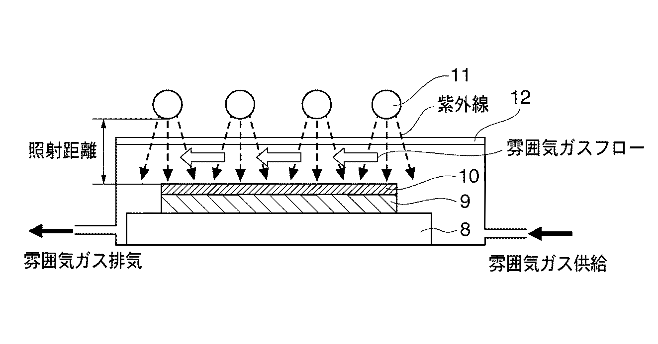
一方、エキシマランプ(キセノンエキシマランプ)は、172nmの波長の紫外線を放射し、例えば空気中では、低圧水銀ランプと異なり、下記反応式(4)に示す高エネルギーの活性原子状酸素O(1D)を直接生成できるという特徴がある(反応式(4)の解離には波長175nm以下が必要なので、低圧水銀ランプの185nmの光ではこの解離は起きない)。また、反応式(5)によりオゾンを生成し、反応式(6)によっても活性原子状酸素を生成できる(反応式(6)は2次反応であり、主たる活性原子状酸素の生成は反応式(4)によると考えられる)。 On the other hand, an excimer lamp (xenon excimer lamp) emits ultraviolet light having a wavelength of 172 nm. Unlike, for example, a low-pressure mercury lamp in air, high-energy active atomic oxygen O ( 1 D shown in the following reaction formula (4) is used. ) Can be directly generated (the dissociation of the reaction formula (4) requires a wavelength of 175 nm or less, so this dissociation does not occur with light of 185 nm from a low-pressure mercury lamp). Further, ozone can be generated by the reaction formula (5), and active atomic oxygen can also be generated by the reaction formula (6) (the reaction formula (6) is a secondary reaction, and the main generation of active atomic oxygen is the reaction formula). (4).
更に、フォトンのエネルギーが696kJ/molと大きいので有機物の結合を切る能力が高いという利点もある(ほとんどの有機物の分子結合エネルギーより高いため分子結合が切れる確率が高くなる)。ただし、172nmの光は、低圧水銀ランプの185nmの光に比べて酸素の吸収係数が約100倍も大きく、酸素に強く吸収されるため、上記オゾンや高エネルギーの活性原子状酸素は、ランプ表面近傍でしか酸化反応が起こせず、大気中での有効照射距離が0〜3mm(臨界照射距離は8mm)と極端に短くなる欠点がある。
以上のようにして、乾燥塗布膜中の有機成分を熱分解・燃焼(酸化)により無機化させながら緻密化させて、金属酸化物微粒子が充填した無機薄膜を得ることができる。
Further, since the energy of photons is as large as 696 kJ / mol, there is an advantage that the ability to cut organic bonds is high (because it is higher than the molecular bond energy of most organic substances, the probability of breaking the molecular bonds increases). However, 172 nm light has an oxygen absorption coefficient about 100 times larger than that of 185 nm light from a low-pressure mercury lamp and is strongly absorbed by oxygen. Therefore, the ozone and high-energy active atomic oxygen are Oxidation reaction takes place only in the vicinity, and there is a drawback that the effective irradiation distance in the atmosphere is extremely shortened to 0 to 3 mm (critical irradiation distance is 8 mm).
As described above, an inorganic thin film filled with metal oxide fine particles can be obtained by densifying the organic component in the dry coating film while making it inorganic by thermal decomposition and combustion (oxidation).
次に、プラズマ照射処理について詳しく説明する。
本発明のプラズマ照射処理に用いるプラズマとしては、マイクロ波プラズマや高周波プラズマ(RFプラズマ)が考えられるが、いずれのプラズマの適用も可能である。
Next, the plasma irradiation process will be described in detail.
As the plasma used for the plasma irradiation treatment of the present invention, microwave plasma or high frequency plasma (RF plasma) can be considered, but any plasma can be applied.
まず、マイクロ波プラズマを用いたマイクロ波プラズマ照射処理について述べると、マイクロ波は極めて短波長の電磁波で、波長3〜30cm(周波数1000M〜10000MHz)程度の電波の総称であり、工業的には、2450MHz、915MHzが利用されるが、2450MHzが一般的である。マイクロ波プラズマは一般的に減圧雰囲気下(圧力2〜200Pa、好ましくは3〜20Pa、更に好ましくは3〜10Pa)で安定形成され、1011〜1012/cm3という高密度プラズマを得ることができる。
その圧力が高すぎる(200Paを越える)とマイクロ波プラズマ形成が困難となってくると同時に、プラズマ中のイオンや活性原子の存在寿命が短くなってイオン濃度や活性原子濃度が低下して、プラズマ照射の効果(無機化、緻密化)が小さくなるため好ましいとは言えない。また、圧力が低すぎる(2Pa未満)と、同様に、マイクロ波プラズマ形成が困難となると同時に、プラズマ中のイオン濃度や活性原子濃度が低下するため好ましいとは言えない。
First, microwave plasma irradiation treatment using microwave plasma will be described. Microwave is an electromagnetic wave having an extremely short wavelength, and is a general term for radio waves having a wavelength of about 3 to 30 cm (frequency 1000 M to 10,000 MHz). 2450 MHz and 915 MHz are used, but 2450 MHz is common. The microwave plasma is generally stably formed under a reduced pressure atmosphere (
If the pressure is too high (over 200 Pa), microwave plasma formation becomes difficult, and at the same time, the existence lifetime of ions and active atoms in the plasma is shortened, and the ion concentration and active atom concentration are lowered. Since the effect of irradiation (mineralization, densification) becomes small, it cannot be said that it is preferable. Similarly, if the pressure is too low (less than 2 Pa), it is difficult to form microwave plasma, and at the same time, the ion concentration and active atom concentration in the plasma are lowered, which is not preferable.
次いで、高周波プラズマを用いた高周波プラズマ照射処理について述べると、高周波はラジオ波(RF:Radio Frequency)の波長の電磁波で、波長1m〜100km(周波数3k〜300MHz)程度の電波の総称である。工業的には、13.56MHz、27.12MHz、40.68MHz等が利用されるが、13.56MHzが一般的である。
高周波プラズマは、マイクロ波プラズマと比べて広範な圧力範囲(圧力2Pa〜100kPa(大気圧))で比較的安定に形成でき、プラズマ密度は109〜1010/cm3程度と、マイクロ波プラズマに比べると幾分低いが、例えば大気圧雰囲気を用いた大気圧高周波プラズマ照射処理であれば装置構造が単純になり装置コストを安価にできる利点がある。
Next, high-frequency plasma irradiation processing using high-frequency plasma will be described. High-frequency is an electromagnetic wave having a radio frequency (RF) wavelength, and is a general term for radio waves having a wavelength of about 1 m to 100 km (frequency 3 k to 300 MHz). Industrially, 13.56 MHz, 27.12 MHz, 40.68 MHz, and the like are used, but 13.56 MHz is common.
The high-frequency plasma can be formed relatively stably in a wider pressure range (
プラズマ照射処理では、プラズマの電子温度が高い(マイクロ波プラズマの電子温度:1eV程度、高周波プラズマ:数eV程度)ため、基板が加熱されるが、その加熱温度はプラズマ照射処理条件(基板とプラズマ発生部の距離(照射距離)、処理時間、入力エネルギー(数百W〜数キロW)等)により100〜数百度まで大きく異なってくるが、基板の材質や無機薄膜の種類等により適宜最適化すれば良い。加熱処理時の加熱温度の設定は、プラズマ照射処理単独で行っても良いし、(加熱装置による)加熱処理とプラズマ照射処理を併用して行っても良い。 In plasma irradiation treatment, the substrate is heated because the electron temperature of plasma is high (electron temperature of microwave plasma: about 1 eV, high-frequency plasma: about several eV), and the heating temperature depends on the plasma irradiation treatment conditions (substrate and plasma). Depending on the distance of the generating part (irradiation distance), processing time, input energy (several hundred watts to several kilowatts, etc.), it varies greatly from 100 to several hundred degrees. Just do it. The setting of the heating temperature at the time of the heat treatment may be performed by the plasma irradiation treatment alone, or may be performed by using both the heat treatment (by the heating device) and the plasma irradiation treatment.
上記マイクロ波と高周波のいずれのプラズマ照射処理においても、酸素含有雰囲気下において無機化や緻密化を大幅に促進する効果を有しており、前述の紫外線等のエネルギー線照射処理と同様に無機薄膜の形成に活用できる。 Both the microwave and high-frequency plasma irradiation treatments have the effect of greatly promoting mineralization and densification in an oxygen-containing atmosphere, and the inorganic thin film is the same as the energy ray irradiation treatment such as ultraviolet rays described above. Can be used to form
ところで、CO2濃度が低く、露点温度が低い(−10℃以下;例えば−10〜−80℃)の酸素含有雰囲気下での無機化により緻密な薄膜を得た後に、必要に応じて、次にCO2濃度が低く、露点温度の高い(0℃以上;例えば0〜30℃)の酸素含有雰囲気ガスを供給しながら無機化処理を行って、より無機化を促進させても良い。
更には、酸素含有雰囲気ガス中での無機化により活物質層(正極、負極)や固体電解質層としての無機薄膜を得た後、必要に応じ、例えば電子導電性の向上等の目的で、その膜の酸素含有量(酸素欠損量、つまり、酸素空孔量)を調節するために、中性雰囲気または還元性雰囲気ガスを供給しながら無機化処理を行うこともできる。
By the way, after obtaining a dense thin film by mineralization in an oxygen-containing atmosphere having a low CO 2 concentration and a low dew point temperature (−10 ° C. or lower; for example, −10 to −80 ° C.), Further, mineralization may be promoted by supplying an oxygen-containing atmosphere gas having a low CO 2 concentration and a high dew point temperature (0 ° C. or higher; for example, 0 to 30 ° C.).
Furthermore, after obtaining an inorganic thin film as an active material layer (positive electrode, negative electrode) or a solid electrolyte layer by mineralization in an oxygen-containing atmosphere gas, if necessary, for example, for the purpose of improving electronic conductivity, In order to adjust the oxygen content of the film (the amount of oxygen deficiency, that is, the amount of oxygen vacancies), an inorganic treatment can be performed while supplying a neutral atmosphere or a reducing atmosphere gas.
本発明で使用する酸素含有雰囲気ガスは、空気、または酸素ガス、あるいは、酸素ガスと中性雰囲気ガス(窒素)・不活性ガス(アルゴン、ヘリウム等)の混合ガスが挙げられるが、安価で入手しやすい空気、特に、CO2が除去された空気(CO2濃度1ppm未満)が好ましい。 The oxygen-containing atmosphere gas used in the present invention includes air, oxygen gas, or a mixed gas of oxygen gas and neutral atmosphere gas (nitrogen) / inert gas (argon, helium, etc.), but is available at a low price. Air that is easy to do, particularly air from which CO 2 has been removed (CO 2 concentration of less than 1 ppm) is preferred.
ここで、酸素含有雰囲気下での単純な加熱処理を用いた無機化工程(つまり、エネルギー線照射処理やプラズマ照射処理との併用がない加熱処理)の加熱温度(ピーク温度)は、300℃以上、より好ましくは350℃以上、更に好ましくは400℃以上の加熱温度で5〜120分間、より好ましくは15〜60分間である。
300℃よりも低い加熱温度(特に270℃未満の加熱温度)では、通常、乾燥塗布膜に含まれる有機成分(有機金属化合物有機バインダー等に含まれる有機成分)の熱分解、あるいは燃焼が不十分となり易く、それら有機成分が活物質層(正極、負極)や固体電解質層に残留して無機化が不十分となり、膜の緻密化も不十分となって、活物質層(正極、負極)や固体電解質層として機能しなくなる恐れがあるため好ましいとは言えない。
Here, the heating temperature (peak temperature) of the mineralization process using a simple heat treatment in an oxygen-containing atmosphere (that is, a heat treatment that is not combined with energy beam irradiation treatment or plasma irradiation treatment) is 300 ° C. or higher. More preferably, it is 350 degreeC or more, More preferably, it is 5-120 minutes at the heating temperature of 400 degreeC or more, More preferably, it is 15-60 minutes.
At a heating temperature lower than 300 ° C. (especially a heating temperature lower than 270 ° C.), the thermal decomposition or combustion of organic components (organic components contained in an organic metal compound organic binder, etc.) contained in the dried coating film is usually insufficient. These organic components remain in the active material layer (positive electrode, negative electrode) or solid electrolyte layer, resulting in insufficient mineralization, insufficient film densification, and active material layer (positive electrode, negative electrode) This is not preferable because it may not function as a solid electrolyte layer.
ただし、加熱処理時間を例えば60分間程度以上と長くした場合や、最終的な活物質層(正極、負極)や固体電解質層の膜厚が50nm程度以下と薄い場合等では、例えば270℃程度でも上記有機成分の熱分解、あるいは燃焼が進行して、膜の無機化が達成される場合もある。
したがって、単純な加熱処理を用いた無機化では、一般的には300℃以上の加熱温度が好ましいが、各工程の条件(膜厚、無機化時間等)によっては、270℃程度の加熱温度も適用可能である。
However, when the heat treatment time is increased to, for example, about 60 minutes or longer, or when the final active material layer (positive electrode, negative electrode) or solid electrolyte layer is as thin as about 50 nm or less, for example, even at about 270 ° C. In some cases, thermal decomposition or combustion of the organic component proceeds to achieve mineralization of the film.
Therefore, in mineralization using a simple heat treatment, a heating temperature of 300 ° C. or higher is generally preferable, but depending on the conditions (film thickness, mineralization time, etc.) of each process, a heating temperature of about 270 ° C. may be used. Applicable.
また、単純な加熱処理を用いた無機化工程での加熱温度の上限は特に限定されないが、用いる無機化装置の種類や基板の耐熱性等の影響を受ける。例えば、安価で最も一般的に用いられるソーダライムガラス基板では、歪点が約510℃であるので、この温度よりも低い温度で無機化することが好ましい。ただし、ソーダライムガラス基板をより耐熱性の高い耐熱性基材上で無機化すれば、基板の歪みを比較的少なくできるため、約600℃程度での無機化も可能である。もちろん、石英ガラス基板、無アルカリガラス基板、高歪点ガラス基板等のより耐熱性が高いガラス基板を用いる場合は、更に高い加熱温度が適用できる。
なお、基板として耐熱性プラスチックであるポリイミド(PI)フィルムを用いた場合は、ポリイミドの種類にもよるが、400℃程度までの無機化が可能である。
Moreover, although the upper limit of the heating temperature in the mineralization process using a simple heat treatment is not particularly limited, it is affected by the type of mineralizer used, the heat resistance of the substrate, and the like. For example, a soda-lime glass substrate that is inexpensive and most commonly used has a strain point of about 510 ° C., and therefore, it is preferable to mineralize at a temperature lower than this temperature. However, if the soda lime glass substrate is mineralized on a heat resistant base material having higher heat resistance, the distortion of the substrate can be relatively reduced, so that the mineralization at about 600 ° C. is also possible. Of course, when a glass substrate having higher heat resistance such as a quartz glass substrate, an alkali-free glass substrate, or a high strain point glass substrate is used, a higher heating temperature can be applied.
When a polyimide (PI) film, which is a heat resistant plastic, is used as the substrate, it can be inorganicized up to about 400 ° C., depending on the type of polyimide.
加熱処理を用いた無機化工程で用いる無機化装置には、ホットプレート、熱風循環無機化炉、電気炉、赤外線加熱装置等が挙げられるが、これらに限定される訳ではない。
赤外線加熱装置の中でも、急速昇温炉(RTA炉:Rapid Thermal Annealing Furnace)は、ハロゲンランプやキセノンフラッシュランプからの強力な赤外線を試料に照射することで極短時間での加熱処理が可能となるため、無機化工程の効率化を図ることができる。
ただし、本発明を実施するためには二酸化炭素(CO2)が低く、露点温度−80℃〜30℃の範囲内で制御された酸素含有雰囲気を用いることが好ましいため、その場合には、上記無機化装置には無機化雰囲気の制御が可能であることが求められる。
Examples of the mineralization apparatus used in the mineralization process using heat treatment include, but are not limited to, a hot plate, a hot-air circulating mineralization furnace, an electric furnace, and an infrared heating apparatus.
Among infrared heating devices, a rapid thermal annealing furnace (RTA furnace) enables heat treatment in a very short time by irradiating a sample with a strong infrared ray from a halogen lamp or a xenon flash lamp. Therefore, the efficiency of the mineralization process can be improved.
However, in order to carry out the present invention, it is preferable to use an oxygen-containing atmosphere that is low in carbon dioxide (CO 2 ) and controlled in the range of dew point temperature of −80 ° C. to 30 ° C. The mineralization apparatus is required to be able to control the mineralization atmosphere.
なお、加熱処理を用いた無機化工程の昇温過程における金属酸化物の結晶化が起こる温度以上までの昇温速度については特に制約はないが、5〜40℃/分の範囲、より一般的には10〜30℃/分である。
5℃/分より昇温速度が遅いと昇温に時間がかかりすぎて効率が悪くなり、一方40℃/分を越える昇温速度を上記無機化装置で実現しようとすると、通常の伝熱型ヒーターではヒーター容量が大きくなりすぎて現実的でない。ただし、上記急速加熱装置(RTA炉)では、100℃/分以上の急速加熱も可能であり、好適に用いることができる。
There is no particular limitation on the rate of temperature increase up to a temperature at which crystallization of the metal oxide occurs in the temperature increase process of the mineralization step using heat treatment, but a range of 5 to 40 ° C./min is more general. Is 10 to 30 ° C./min.
If the heating rate is slower than 5 ° C./min, it takes too much time to raise the temperature and the efficiency is deteriorated. On the other hand, if it is attempted to realize a heating rate exceeding 40 ° C./min with the above mineralizer, In the case of a heater, the heater capacity becomes too large, which is not realistic. However, in the rapid heating apparatus (RTA furnace), rapid heating at 100 ° C./min or more is possible and can be used preferably.
前述の中性雰囲気または還元性雰囲気ガスを供給しながらの無機化処理で用いる中性雰囲気は、窒素ガス、不活性ガス(アルゴン、ヘリウム等)のいずれか1種以上からなり、還元性雰囲気は、水素ガスまたは該中性雰囲気に水素または有機溶剤蒸気(メタノール等の有機ガス)の少なくとも1種以上が含まれる雰囲気などが挙げられるが、これらに限定されない。1〜2%水素−99〜98%窒素の混合ガスは、大気に漏洩しても爆発の恐れがないため好ましい還元性雰囲気である。 The neutral atmosphere used in the mineralization treatment while supplying the neutral atmosphere or reducing atmosphere gas is composed of one or more of nitrogen gas and inert gas (argon, helium, etc.). An atmosphere in which at least one or more of hydrogen or an organic solvent vapor (an organic gas such as methanol) is contained in the hydrogen gas or the neutral atmosphere is exemplified, but not limited thereto. A mixed gas of 1-2% hydrogen-99-98% nitrogen is a preferable reducing atmosphere because there is no risk of explosion even if it leaks into the atmosphere.
中性雰囲気または還元性雰囲気下での無機化の処理条件は、加熱温度が250℃以上、より好ましくは350℃以上の加熱温度で5〜120分間、より好ましくは15〜60分間である。
また、この加熱温度の上限は特に限定されないが、無機化工程で用いる無機化装置の種類や基板の耐熱性に影響受ける点は、酸素含有雰囲気下での無機化と同様である。
The treatment conditions for mineralization in a neutral or reducing atmosphere are a heating temperature of 250 ° C. or higher, more preferably a heating temperature of 350 ° C. or higher, for 5 to 120 minutes, more preferably 15 to 60 minutes.
Moreover, although the upper limit of this heating temperature is not specifically limited, The point affected by the kind of mineralization apparatus used at an inorganicization process and the heat resistance of a board | substrate is the same as that of mineralization in oxygen-containing atmosphere.
なお、加熱処理を用いた無機化工程における、CO2濃度の低い各種露点温度の酸素含有雰囲気下での無機化、及び中性雰囲気または還元性雰囲気下の無機化は、連続して行うことができる。即ち、乾燥塗布膜が形成された基板の無機化において、例えば、基板の温度を300℃以上の加熱温度に昇温した後、その温度を保ったまま、雰囲気だけをCO2濃度の低い露点温度の異なる酸素含有雰囲気、あるいは、中性雰囲気または還元性雰囲気に切替えればよい。 Note that, in the mineralization step using heat treatment, mineralization in an oxygen-containing atmosphere having various dew point temperatures with low CO 2 concentration and mineralization in a neutral or reducing atmosphere can be performed continuously. it can. That is, in the mineralization of a substrate on which a dry coating film is formed, for example, after raising the temperature of the substrate to a heating temperature of 300 ° C. or higher, the dew point temperature with a low CO 2 concentration is maintained while maintaining the temperature. May be switched to different oxygen-containing atmospheres, or neutral atmospheres or reducing atmospheres.
本発明に係る薄膜固体二次電池用の薄膜は、塗布法という極めて簡便な方法で形成できるため、薄膜固体二次電池の正極活物質層、固体電解質層、負極活物質層に適用することで、薄型化、小型化が可能な薄膜固体二次電池の低コスト化に大きく貢献することができるものである。 Since the thin film for a thin film solid secondary battery according to the present invention can be formed by a very simple method called a coating method, it can be applied to the positive electrode active material layer, solid electrolyte layer, and negative electrode active material layer of the thin film solid secondary battery. Thus, the present invention can greatly contribute to cost reduction of a thin film solid state secondary battery that can be reduced in thickness and size.
以下、実施例を用いて本発明を詳細に説明するが、本発明はこれら実施例に限定されるものではない。 EXAMPLES Hereinafter, although this invention is demonstrated in detail using an Example, this invention is not limited to these Examples.
[正極活物質層形成用塗布液の作製]
リチウム(I)−tert−ブトキシド(室温で固体)[Li(C4H9O)](分子量=80.05)3.46g、蟻酸コバルト(II)(室温で固体)[Co(COOH)2・2H2O](分子量=185.0)8.0g、3−アミノ−1−プロパノール88.54gを混合し、120℃に加温して120分間攪拌して溶解させ、次に、得られた溶解液10gに、プロピレングリコールモノメチルエーテル(PGM)9.996g、界面活性剤0.004gを混合して均一になるまで良く攪拌し、リチウム(I)−tert−ブトキシドと蟻酸コバルト(II)を合計で5.73質量%(ヒドロキシプロピルセルロースは非含有)含有する正極活物質層形成用塗布液(リチウム(I)−tert−ブトキシド:蟻酸コバルト(II)=1:1[モル比])を作製した。
[Preparation of coating liquid for forming positive electrode active material layer]
Lithium (I) -tert-butoxide (solid at room temperature) [Li (C 4 H 9 O)] (molecular weight = 80.05) 3.46 g, cobalt (II) formate (solid at room temperature) [Co (COOH) 2 2H 2 O] (molecular weight = 185.0) 8.0 g, 3-amino-1-propanol 88.54 g mixed, heated to 120 ° C. and stirred for 120 minutes to dissolve, then obtained To 10 g of the resulting solution, 9.996 g of propylene glycol monomethyl ether (PGM) and 0.004 g of a surfactant were mixed and stirred well until uniform, and lithium (I) -tert-butoxide and cobalt formate (II) were added. Coating liquid for forming positive electrode active material layer (lithium (I) -tert-butoxide: cobalt formate (II)) containing a total of 5.73% by mass (not containing hydroxypropyl cellulose) = 1: 1 [molar ratio]).
[薄膜の作製]
作製した正極活物質層形成用塗布液を、25℃の無アルカリガラス基板(5cm×5cm×0.7mm厚さ;ヘイズ値=0.26%、可視光線透過率=91.2%)上の全面にスピンコーティング(3000rpm×60sec)した後、大気中150℃で5分間乾燥して乾燥塗布膜(膜厚:約120nm、表面抵抗値:>1×10¹³Ω/□(絶縁))を得た。
次に、図5の塗布法による薄膜の製造方法における加熱処理及びエネルギー線照射工程を用いた無機化工程の模式図に示すように、この乾燥塗布膜10を有する基板9を、CO2濃度1ppm未満で露点温度−55℃の低湿度空気中150℃に昇温(昇温速度:30℃/分)し、CO2濃度1ppm未満で露点温度−55℃の低湿度空気を紫外線照射窓12(合成石英板;厚さ2mm)と基板9との間に供給しながら150℃に加熱したままで低圧水銀ランプ11を30分間照射する加熱処理を併用したエネルギー線照射処理を行い、乾燥塗布膜10の無機化(有機成分の分解または燃焼)と緻密化を促進して、コバルトを含むリチウム複合酸化物(LCO:LiCoO2)を主成分とする正極活物質層からなる実施例1に係る薄膜固体二次電池用の薄膜(膜厚:約62nm)を作製した。
なお、低圧水銀ランプ11と基板9との距離(照射距離)は10.5mmで、254nmの光の照度:約20mW/cm2、185nmの光の推定照度:約5mW/cm2であった。更に、基板9と紫外線照射窓12の間隔は3.5mmでその間を流れる雰囲気ガス(CO2濃度1ppm未満で露点温度−55℃の低湿度空気)の平均流速は約0.29m/秒)であった。
[Preparation of thin film]
The produced coating liquid for forming a positive electrode active material layer was formed on a non-alkali glass substrate (5 cm × 5 cm × 0.7 mm thickness; haze value = 0.26%, visible light transmittance = 91.2%) at 25 ° C. After spin coating (3000 rpm × 60 sec) on the entire surface, the coating was dried in air at 150 ° C. for 5 minutes to obtain a dry coating film (film thickness: about 120 nm, surface resistance:> 1 × 10 13 Ω / □ (insulation)) It was.
Next, as shown in the schematic diagram of mineralization process using heat treatment and energy ray irradiation step in the manufacturing method of a thin film by coating method of FIG. 5, a
The distance (irradiation distance) between the low-
[特性評価]
次に作製した薄膜における塗布法により形成された正極活物質層の表面抵抗、膜厚、比抵抗(=表面抵抗×膜厚)、結晶子サイズ(以下、結晶子径と呼ぶこともある)の諸特性を測定し、その結果を表1に示す。
X線回折測定の結果から上記塗布法により形成された正極活物質層はアモルファス膜であり、更に、実施例1の正極活物質層の断面を透過電子顕微鏡で観察したところ、主に3nm未満の金属酸化物微粒子(アモルファス状微結晶)が緻密に充填した無機薄膜が観察されている。
また、上記薄膜の無機化度合いの評価を、フーリエ変換赤外分光分析(FTIR法)により行ったところ、薄膜からは有機官能基(C=O等)や水酸基(−OH)はほとんど観察されず、無機化していることが確認された(尚、FTIR法による測定では、ガラス基板からの影響が懸念されたため、測定に影響を与えないアルミニウム(Al)を予め蒸着したAl蒸着膜付ガラス基板を用い、そのAl蒸着膜上に、上述と同様の方法で薄膜を形成して評価している)。
[Characteristic evaluation]
Next, the surface resistance, film thickness, specific resistance (= surface resistance × film thickness), and crystallite size (hereinafter also referred to as crystallite diameter) of the positive electrode active material layer formed by the coating method in the thin film produced Various characteristics were measured and the results are shown in Table 1.
From the result of X-ray diffraction measurement, the positive electrode active material layer formed by the above coating method is an amorphous film. Further, when the cross section of the positive electrode active material layer of Example 1 was observed with a transmission electron microscope, it was mainly less than 3 nm. An inorganic thin film in which metal oxide fine particles (amorphous microcrystals) are densely packed has been observed.
In addition, when the degree of mineralization of the thin film was evaluated by Fourier transform infrared spectroscopy (FTIR method), organic functional groups (C = O, etc.) and hydroxyl groups (-OH) were hardly observed from the thin film. It was confirmed that the glass substrate was inorganicized. (In the measurement by the FTIR method, there was a concern about the influence from the glass substrate. And a thin film is formed on the Al deposited film by the same method as described above and evaluated).
塗布法により形成された上記正極活物質層の表面抵抗は、三菱化学株式会社製の表面抵抗計ハイレスタIP(MCP−HT260)を用い測定した。尚、測定される表面抵抗は、電子伝導とイオン伝導の両方を合せて測定していると考えられるが、例えば表面抵抗が105〜106Ω/□(オーム・パー・スクエア)程度と低い値の場合は電子伝導が主体であり、表面抵抗が108〜1012Ω/□と高い値の場合は、250〜500Vの高電圧を測定プローブに印加しての測定であり、イオン伝導の寄与も大きくなっていると考えられる。
膜厚は、オプティカルプロファイラー(Zygo社製 NewView6200)を用いて測定した。
結晶子サイズは、X線回折測定を行い、Scherrer法により求めた。
The surface resistance of the positive electrode active material layer formed by the coating method was measured using a surface resistance meter Hiresta IP (MCP-HT260) manufactured by Mitsubishi Chemical Corporation. In addition, although it is thought that the measured surface resistance is combining both electron conduction and ion conduction, for example, the surface resistance is as low as about 10 5 to 10 6 Ω / □ (ohm per square). In the case of the value, the electron conduction is mainly, and in the case where the surface resistance is as high as 10 8 to 10 12 Ω / □, the measurement is performed by applying a high voltage of 250 to 500 V to the measurement probe. The contribution is thought to have increased.
The film thickness was measured using an optical profiler (New View 6200 manufactured by Zygo).
The crystallite size was determined by the Scherrer method after X-ray diffraction measurement.
[正極活物質層形成用塗布液の作製]
リチウム(I)−tert−ブトキシド(室温で固体)[Li(C4H9O)](分子量=80.05)9.07g、蟻酸ニッケル(II)(室温で固体)[Ni(HCOO)2・2H2O](分子量=184.77)20.93g、3−アミノ−1−プロパノール70gを混合し、120℃に加温して120分間攪拌して溶解させ、次に、得られた溶解液10gに、ジエチレングリコールモノメチルエーテル9.996g、界面活性剤0.004gを混合して均一になるまで良く攪拌し、リチウム(I)−tert−ブトキシドと蟻酸ニッケル(II)を合計で10質量%(ヒドロキシプロピルセルロースは非含有)含有する正極活物質層形成用塗布液(リチウム(I)−tert−ブトキシド:蟻酸ニッケル(II)=1:1[モル比])を作製した。
[Preparation of coating liquid for forming positive electrode active material layer]
Lithium (I) -tert-butoxide (solid at room temperature) [Li (C 4 H 9 O)] (molecular weight = 80.05) 9.07 g, nickel (II) formate (solid at room temperature) [Ni (HCOO) 2 2H 2 O] (molecular weight = 184.77) 20.93 g and 3-amino-1-propanol 70 g are mixed, heated to 120 ° C. and stirred for 120 minutes to dissolve, and then the resulting dissolution To 10 g of the liquid, 9.996 g of diethylene glycol monomethyl ether and 0.004 g of a surfactant were mixed and stirred well until uniform, and lithium (I) -tert-butoxide and nickel (II) formate totaled 10% by mass ( Coating liquid for forming positive electrode active material layer containing no hydroxypropyl cellulose) (lithium (I) -tert-butoxide: nickel formate (II) = 1: 1 [mol Ratio]).
[薄膜の作製]
作製した正極活物質層形成用塗布液を、25℃の無アルカリガラス基板(5cm×5cm×0.7mm厚さ;ヘイズ値=0.26%、可視光線透過率=91.2%)上の全面にスピンコーティング(3000rpm×60sec)した後、大気中150℃で5分間乾燥して乾燥塗布膜(膜厚:約120nm)を得た。
次に、図5の塗布法による薄膜の製造方法における加熱処理及びエネルギー線照射工程を用いた無機化工程の模式図に示すように、この乾燥塗布膜10を有する基板9を、CO2濃度1ppm未満で露点温度−30℃の低湿度空気中150℃に昇温(昇温速度:30℃/分)し、CO2濃度1ppm未満で露点温度−30℃の低湿度空気を紫外線照射窓12(合成石英板;厚さ2mm)と基板9との間に供給しながら150℃に加熱したままで低圧水銀ランプ11を20分間照射する加熱処理を併用したエネルギー線照射処理を行い、乾燥塗布膜10の無機化(有機成分の分解または燃焼)と緻密化を促進して、ニッケルを含むリチウム複合酸化物(LNO:LiNiO2)を主成分とする正極活物質層からなる実施例2に係る薄膜固体二次電池用の薄膜(膜厚:約45nm)を作製した。
なお、低圧水銀ランプ11と基板9との距離(照射距離)は10.5mmで、254nmの光の照度:約20mW/cm2、185nmの光の推定照度:約5mW/cm2であった。更に、基板9と紫外線照射窓12の間隔は3.5mmでその間を流れる雰囲気ガス(CO2濃度1ppm未満で露点温度−30℃の低湿度空気)の平均流速は約0.29m/秒)であった。
[Preparation of thin film]
The produced coating liquid for forming a positive electrode active material layer was formed on a non-alkali glass substrate (5 cm × 5 cm × 0.7 mm thickness; haze value = 0.26%, visible light transmittance = 91.2%) at 25 ° C. After spin coating (3000 rpm × 60 sec) on the entire surface, the coating was dried in air at 150 ° C. for 5 minutes to obtain a dry coating film (film thickness: about 120 nm).
Next, as shown in the schematic diagram of the inorganic treatment process using the heat treatment and energy beam irradiation process in the thin film manufacturing method by the coating method of FIG. 5, the
The distance (irradiation distance) between the low-
[特性評価]
次に作製した薄膜における塗布法により形成された正極活物質層の表面抵抗、膜厚、比抵抗(=表面抵抗×膜厚)、結晶子サイズの諸特性を測定し、その結果を表1に示す。
X線回折測定の結果から上記塗布法により形成された正極活物質層はアモルファス膜であり、更に、実施例2の正極活物質層の断面を透過電子顕微鏡で観察したところ、主に3nm未満の金属酸化物微粒子(アモルファス状微結晶)が緻密に充填した無機薄膜が観察されている。
また、上記薄膜の無機化度合いの評価を、フーリエ変換赤外分光分析(FTIR法)により行ったところ、薄膜からは有機官能基(C=O等)や水酸基(−OH)はほとんど観察されず、無機化していることが確認された(尚、FTIR法による測定では、ガラス基板からの影響が懸念されたため、測定に影響を与えないアルミニウム(Al)を予め蒸着したAl蒸着膜付ガラス基板を用い、そのAl蒸着膜上に、上述と同様の方法で薄膜を形成して評価している)。
[Characteristic evaluation]
Next, the surface resistance, film thickness, specific resistance (= surface resistance × film thickness) and crystallite size characteristics of the positive electrode active material layer formed by the coating method on the prepared thin film were measured, and the results are shown in Table 1. Show.
From the result of the X-ray diffraction measurement, the positive electrode active material layer formed by the above coating method is an amorphous film. Further, when the cross section of the positive electrode active material layer of Example 2 was observed with a transmission electron microscope, it was mainly less than 3 nm. An inorganic thin film in which metal oxide fine particles (amorphous microcrystals) are densely packed has been observed.
In addition, when the degree of mineralization of the thin film was evaluated by Fourier transform infrared spectroscopy (FTIR method), organic functional groups (C = O, etc.) and hydroxyl groups (-OH) were hardly observed from the thin film. It was confirmed that the glass substrate was inorganicized. (In the measurement by the FTIR method, there was a concern about the influence from the glass substrate. And a thin film is formed on the Al deposited film by the same method as described above and evaluated).
[正極活物質層形成用塗布液の作製]
アセチルアセトンリチウム(室温で固体)[Li(C5H7O2)](分子量=106.05)1.31g、アセチルアセトンマンガン(室温で固体)[Mn(C5H7O2)3](分子量=352.26)8.69g、N−メチル−2−ピロリドン(NMP)39g、ヒドロキシプロピルセルロース(HPC;低分子量タイプ)1gを混合し、120℃に加温して120分間攪拌して溶解させ、次に、得られた溶解液5gに、シクロヘキサノン6g、プロピレングリコールモノメチルエーテル(PGM)3g、メチルエチルケトン(MEK)6g、界面活性剤0.004gを混合して均一になるまで良く攪拌し、アセチルアセトンリチウムとアセチルアセトンマンガンを合計で5質量%、ヒドロキシプロピルセルロースを0.5質量%含有する正極活物質層形成用塗布液(アセチルアセトンリチウム:アセチルアセトンマンガン=1:2[モル比])を作製した。
[Preparation of coating liquid for forming positive electrode active material layer]
Lithium acetylacetone (solid at room temperature) [Li (C 5 H 7 O 2 )] (molecular weight = 106.05) 1.31 g, manganese acetylacetone (solid at room temperature) [Mn (C 5 H 7 O 2 ) 3 ] (molecular weight = 352.26) 8.69 g, N-methyl-2-pyrrolidone (NMP) 39 g, hydroxypropylcellulose (HPC; low molecular weight type) 1 g are mixed, heated to 120 ° C. and stirred for 120 minutes to dissolve. Next, 5 g of the resulting solution was mixed with 6 g of cyclohexanone, 3 g of propylene glycol monomethyl ether (PGM), 6 g of methyl ethyl ketone (MEK), and 0.004 g of a surfactant, and stirred well until uniform. And 5% by mass of acetylacetone manganese and 0.5% hydroxypropylcellulose % Positive electrode active material layer forming coating solution containing (acetylacetone lithium acetylacetone manganese = 1: 2 [molar ratio]) was prepared.
[薄膜の作製]
作製した正極活物質層形成用塗布液を、25℃の無アルカリガラス基板(5cm×5cm×0.7mm厚さ;ヘイズ値=0.26%、可視光線透過率=91.2%)上の全面にスピンコーティング(1500rpm×60sec)した後、大気中100℃で5分間乾燥して乾燥塗布膜(膜厚:約105nm、表面抵抗値:>1×10¹³Ω/□(絶縁))を得た。
次に、図5の塗布法による薄膜の製造方法における加熱処理及びエネルギー線照射工程を用いた無機化工程の模式図に示すように、この乾燥塗布膜10を有する基板9を、CO2濃度1ppm未満で露点温度−55℃の低湿度空気中150℃に昇温(昇温速度:30℃/分)し、CO2濃度1ppm未満で露点温度−55℃の低湿度空気を紫外線照射窓12(合成石英板;厚さ2mm)と基板9との間に供給しながら150℃に加熱したままで低圧水銀ランプ11を10分間照射する加熱処理を併用したエネルギー線照射処理を行い、乾燥塗布膜10の無機化(有機成分の分解または燃焼)と緻密化を促進して、マンガンを含むリチウム複合酸化物(LMO:LiMn2O4)を主成分とする正極活物質層からなる実施例3に係る薄膜固体二次電池用の薄膜(膜厚:約66nm)を作製した。
なお、低圧水銀ランプ11と基板9との距離(照射距離)は10.5mmで、254nmの光の照度:約20mW/cm2、185nmの光の推定照度:約5mW/cm2であった。
更に、基板9と紫外線照射窓12の間隔は3.5mmでその間を流れる雰囲気ガス(CO2濃度1ppm未満で露点温度−55℃の低湿度空気)の平均流速は約0.29m/秒)であった。
[Preparation of thin film]
The produced coating liquid for forming a positive electrode active material layer was formed on a non-alkali glass substrate (5 cm × 5 cm × 0.7 mm thickness; haze value = 0.26%, visible light transmittance = 91.2%) at 25 ° C. After spin coating on the entire surface (1500 rpm × 60 sec), drying in the atmosphere at 100 ° C. for 5 minutes yields a dry coating film (film thickness: about 105 nm, surface resistance:> 1 × 10 13 Ω / □ (insulation)) It was.
Next, as shown in the schematic diagram of the inorganic treatment process using the heat treatment and energy beam irradiation process in the thin film manufacturing method by the coating method of FIG. 5, the
The distance (irradiation distance) between the low-
Furthermore, the distance between the
[特性評価]
次に作製した薄膜における塗布法により形成された正極活物質層の表面抵抗、膜厚、比抵抗(=表面抵抗×膜厚)、結晶子サイズの諸特性を測定し、その結果を表1に示す。
X線回折測定の結果から上記塗布法により形成された正極活物質層はアモルファス膜であり、更に、実施例3の正極活物質層の断面を透過電子顕微鏡で観察したところ、主に3nm未満の金属酸化物微粒子(アモルファス状微結晶)が緻密に充填した無機薄膜が観察されている。
[Characteristic evaluation]
Next, the surface resistance, film thickness, specific resistance (= surface resistance × film thickness) and crystallite size characteristics of the positive electrode active material layer formed by the coating method on the prepared thin film were measured, and the results are shown in Table 1. Show.
From the result of X-ray diffraction measurement, the positive electrode active material layer formed by the above coating method is an amorphous film. Further, when the cross section of the positive electrode active material layer of Example 3 was observed with a transmission electron microscope, it was mainly less than 3 nm. An inorganic thin film in which metal oxide fine particles (amorphous microcrystals) are densely packed has been observed.
また、上記薄膜の無機化度合いの評価を、フーリエ変換赤外分光分析(FTIR法)により行ったところ、薄膜からは有機官能基(C=O等)や水酸基(−OH)はほとんど観察されず、無機化していることが確認された(尚、FTIR法による測定では、ガラス基板からの影響が懸念されたため、測定に影響を与えないアルミニウム(Al)を予め蒸着したAl蒸着膜付ガラス基板を用い、そのAl蒸着膜上に、上述と同様の方法で薄膜を形成して評価している)。 In addition, when the degree of mineralization of the thin film was evaluated by Fourier transform infrared spectroscopy (FTIR method), organic functional groups (C = O, etc.) and hydroxyl groups (-OH) were hardly observed from the thin film. It was confirmed that the glass substrate was inorganicized. (In the measurement by the FTIR method, there was a concern about the influence from the glass substrate. And a thin film is formed on the Al deposited film by the same method as described above and evaluated).
[薄膜の作製]
実施例3の正極活物質層形成用塗布液を、25℃の無アルカリガラス基板(5cm×5cm×0.7mm厚さ;ヘイズ値=0.26%、可視光線透過率=91.2%)上の全面にスピンコーティング(2000rpm×60sec)した後、大気中100℃で5分間乾燥して乾燥塗布膜(膜厚:約88nm、表面抵抗値:>1×10¹³Ω/□(絶縁))を得た。
次に図5の模式図に示すように、この乾燥塗布膜10を有する基板9を、CO2濃度1ppm未満で露点温度−55℃の低湿度空気中で、加熱処理を併用せずに(加熱装置8を用いずに)、CO2濃度1ppm未満で露点温度−55℃の低湿度空気を紫外線照射窓12(合成石英板;厚さ2mm)と基板9との間に供給しながら低圧水銀ランプ11を10分間照射するエネルギー線照射処理を行い、乾燥塗布膜10の無機化(有機成分の分解または燃焼)と緻密化を促進してマンガンを含むリチウム複合酸化物(LMO:LiMn2O4)を主成分とする無機薄膜(膜厚:約47nm)を得た。正極活物質層形成用塗布液を用いて同様の膜形成操作を繰り返し、この無機薄膜を2層積層して、マンガンを含むリチウム複合酸化物(LMO:LiMn2O4)を主成分とする正極活物質層からなる実施例4に係る薄膜固体二次電池用の薄膜(膜厚:約94nm)を作製した。
なお、低圧水銀ランプ11と基板9との距離(照射距離)は10.5mmで、254nmの光の照度:約20mW/cm2、185nmの光の推定照度:約5mW/cm2であった。更に、基板9と紫外線照射窓12の間隔は3.5mmでその間を流れる雰囲気ガス(CO2濃度1ppm未満で露点温度−55℃の低湿度空気)の平均流速は約0.29m/秒)であった。
また、上記加熱処理を併用しないエネルギー線照射処理において、低圧水銀ランプ11から放出される熱線によって、基板温度は40〜42℃程度まで上昇していることが確認された。
[Preparation of thin film]
The coating liquid for forming the positive electrode active material layer of Example 3 was an alkali-free glass substrate at 25 ° C. (5 cm × 5 cm × 0.7 mm thickness; haze value = 0.26%, visible light transmittance = 91.2%). After spin coating (2000 rpm × 60 sec) on the entire upper surface, it was dried in air at 100 ° C. for 5 minutes to dry coating film (film thickness: about 88 nm, surface resistance:> 1 × 10 13 Ω / □ (insulation)) Got.
Next, as shown in the schematic diagram of FIG. 5, the
The distance (irradiation distance) between the low-
In addition, in the energy ray irradiation treatment not using the above heat treatment, it was confirmed that the substrate temperature was raised to about 40 to 42 ° C. by the heat rays emitted from the low
[特性評価]
次に作製した薄膜における塗布法により形成された正極活物質層の表面抵抗、膜厚、比抵抗(=表面抵抗×膜厚)、結晶子サイズの諸特性を測定し、その結果を表1に示す。
X線回折測定の結果から上記塗布法により形成された正極活物質層はアモルファス膜であり、更に、実施例4の正極活物質層の断面を透過電子顕微鏡で観察したところ、主に3nm未満の金属酸化物微粒子(アモルファス状微結晶)が緻密に充填した無機薄膜が観察されている。
[Characteristic evaluation]
Next, the surface resistance, film thickness, specific resistance (= surface resistance × film thickness) and crystallite size characteristics of the positive electrode active material layer formed by the coating method on the prepared thin film were measured, and the results are shown in Table 1. Show.
From the result of X-ray diffraction measurement, the positive electrode active material layer formed by the above coating method was an amorphous film. Further, when the cross section of the positive electrode active material layer of Example 4 was observed with a transmission electron microscope, it was mainly less than 3 nm. An inorganic thin film in which metal oxide fine particles (amorphous microcrystals) are densely packed has been observed.
また、上記薄膜の無機化度合いの評価を、フーリエ変換赤外分光分析(FTIR法)により行ったところ、薄膜からは有機官能基(C=O等)や水酸基(−OH)はほとんど観察されず、無機化していることが確認された(尚、FTIR法による測定では、ガラス基板からの影響が懸念されたため、測定に影響を与えないアルミニウム(Al)を予め蒸着したAl蒸着膜付ガラス基板を用い、そのAl蒸着膜上に、上述と同様の方法で薄膜を形成して評価している)。 In addition, when the degree of mineralization of the thin film was evaluated by Fourier transform infrared spectroscopy (FTIR method), organic functional groups (C = O, etc.) and hydroxyl groups (-OH) were hardly observed from the thin film. It was confirmed that the glass substrate was inorganicized. (In the measurement by the FTIR method, there was a concern about the influence from the glass substrate. And a thin film is formed on the Al deposited film by the same method as described above and evaluated).
[負極活物質層形成用塗布液の作製]
アセチルアセトンリチウム(室温で固体)[Li(C5H7O2)](分子量=106.05)1.78g、アセチルアセトンチタン(室温で液体)[Ti(C4H9O)2(C5H7O2)2](分子量=392.32)8.22g、N−メチル−2−ピロリドン(NMP)39g、ヒドロキシプロピルセルロース(HPC;低分子量タイプ)1gを混合し、120℃に加温して120分間攪拌して溶解させ、次に、得られた溶解液5gに、シクロヘキサノン6g、プロピレングリコールモノメチルエーテル(PGM)3g、メチルエチルケトン(MEK)6g、界面活性剤0.004gを混合して均一になるまで良く攪拌し、アセチルアセトンリチウムとアセチルアセトンチタンを合計で5質量%、ヒドロキシプロピルセルロースを0.5質量%含有する負極活物質層形成用塗布液(アセチルアセトンリチウム:アセチルアセトンチタン=4:5[モル比])を作製した。
[Preparation of coating liquid for forming negative electrode active material layer]
Lithium acetylacetone (solid at room temperature) [Li (C 5 H 7 O 2 )] (molecular weight = 106.05) 1.78 g, titanium acetylacetone (liquid at room temperature) [Ti (C 4 H 9 O) 2 (C 5 H 7 O 2 ) 2 ] (molecular weight = 392.32) 8.22 g, N-methyl-2-pyrrolidone (NMP) 39 g, and hydroxypropylcellulose (HPC; low molecular weight type) 1 g are mixed and heated to 120 ° C. The mixture is stirred for 120 minutes, and then mixed with 5 g of the obtained solution, 6 g of cyclohexanone, 3 g of propylene glycol monomethyl ether (PGM), 6 g of methyl ethyl ketone (MEK), and 0.004 g of a surfactant are mixed uniformly. Stir well until 5% by mass of lithium acetylacetone and titanium acetylacetone in total, hydroxypropylcellulose A coating liquid for forming a negative electrode active material layer (acetylacetone lithium: acetylacetone titanium = 4: 5 [molar ratio]) containing 0.5% by mass of sucrose was prepared.
[薄膜の作製]
作製した負極活物質層形成用塗布液を、25℃の無アルカリガラス基板(10cm×10cm×0.7mm厚さ;ヘイズ値=0.26%、可視光線透過率=91.2%)上の全面にスピンコーティング(1000rpm×60sec)した後、大気中100℃で5分間乾燥して乾燥塗布膜(膜厚:約100nm、表面抵抗値:>1×10¹³Ω/□(絶縁))を得た。図5の模式図に示すように、この乾燥塗布膜10を有する基板9を、CO2濃度1ppm未満で露点温度−55℃の低湿度空気中150℃に昇温(昇温速度:30℃/分)し、CO2濃度1ppm未満で露点温度−55℃の低湿度空気を紫外線照射窓12(合成石英板;厚さ2mm)と基板9との間に供給しながら150℃に加熱したままで低圧水銀ランプ11を10分間照射する加熱処理を併用したエネルギー線照射処理を行い、乾燥塗布膜10の無機化(有機成分の分解または燃焼)と緻密化を促進して、リチウム−チタン酸化物(LTO:Li4Ti5O12)を主成分とする負極活物質層からなる実施例5に係る薄膜固体二次電池用の薄膜(膜厚:約58nm)を作製した。
なお、低圧水銀ランプ11と基板9との距離(照射距離)は10.5mmで、254nmの光の照度:約20mW/cm2、185nmの光の推定照度:約5mW/cm2であった。更に、基板9と紫外線照射窓12の間隔は3.5mmでその間を流れる雰囲気ガス(CO2濃度1ppm未満で露点温度−55℃の低湿度空気)の平均流速は約0.29m/秒)であった。
[Preparation of thin film]
The prepared coating liquid for forming a negative electrode active material layer was placed on a non-alkali glass substrate (10 cm × 10 cm × 0.7 mm thickness; haze value = 0.26%, visible light transmittance = 91.2%) at 25 ° C. After spin coating (1000 rpm × 60 sec) on the entire surface, the coating was dried in air at 100 ° C. for 5 minutes to obtain a dry coating film (film thickness: about 100 nm, surface resistance:> 1 × 10 13 Ω / □ (insulation)) It was. As shown in the schematic diagram of FIG. 5, the
The distance (irradiation distance) between the low-
[特性評価]
次に作製した薄膜における塗布法により形成された負極活物質層の表面抵抗、膜厚、比抵抗(=表面抵抗×膜厚)、結晶子サイズの諸特性を測定し、その結果を表1に示す。
X線回折測定の結果から上記塗布法により形成された負極活物質層はアモルファス膜であり、更に、実施例5の負極活物質層の断面を透過電子顕微鏡で観察したところ、主に3nm未満の金属酸化物微粒子(アモルファス状微結晶)が緻密に充填した無機薄膜が観察されている。
また、上記薄膜の無機化度合いの評価を、フーリエ変換赤外分光分析(FTIR法)により行ったところ、薄膜からは有機官能基(C=O等)や水酸基(−OH)はほとんど観察されず、無機化していることが確認された(尚、FTIR法による測定では、ガラス基板からの影響が懸念されたため、測定に影響を与えないアルミニウム(Al)を予め蒸着したAl蒸着膜付ガラス基板を用い、そのAl蒸着膜上に、上述と同様の方法で薄膜を形成して評価している)。
[Characteristic evaluation]
Next, the surface resistance, film thickness, specific resistance (= surface resistance × film thickness), and crystallite size characteristics of the negative electrode active material layer formed by the coating method on the prepared thin film were measured, and the results are shown in Table 1. Show.
From the result of the X-ray diffraction measurement, the negative electrode active material layer formed by the above coating method was an amorphous film. Further, when the cross section of the negative electrode active material layer of Example 5 was observed with a transmission electron microscope, it was mainly less than 3 nm. An inorganic thin film in which metal oxide fine particles (amorphous microcrystals) are densely packed has been observed.
In addition, when the degree of mineralization of the thin film was evaluated by Fourier transform infrared spectroscopy (FTIR method), organic functional groups (C = O, etc.) and hydroxyl groups (-OH) were hardly observed from the thin film. It was confirmed that the glass substrate was inorganicized. (In the measurement by the FTIR method, there was a concern about the influence from the glass substrate. And a thin film is formed on the Al deposited film by the same method as described above and evaluated).
[負極活物質層形成用塗布液の作製]
アセチルアセトンリチウム(室温で固体)[Li(C5H7O2)](分子量=106.05)1.78g、アセチルアセトンチタン(室温で液体)[Ti(C4H9O)2(C5H7O2)2](分子量=392.32)8.22g、N−メチル−2−ピロリドン(NMP)39g、ヒドロキシプロピルセルロース(HPC;低分子量タイプ)1gを混合し、120℃に加温して120分間攪拌して溶解させ、次に、得られた溶解液10gに、シクロヘキサノン3.996g、プロピレングリコールモノメチルエーテル(PGM)2g、メチルエチルケトン(MEK)4g、界面活性剤0.004gを混合して均一になるまで良く攪拌し、アセチルアセトンリチウムとアセチルアセトンチタンを合計で10質量%、ヒドロキシプロピルセルロースを1.0質量%含有する負極活物質層形成用塗布液(アセチルアセトンリチウム:アセチルアセトンチタン=4:5[モル比])を作製した。
[Preparation of coating liquid for forming negative electrode active material layer]
Lithium acetylacetone (solid at room temperature) [Li (C 5 H 7 O 2 )] (molecular weight = 106.05) 1.78 g, titanium acetylacetone (liquid at room temperature) [Ti (C 4 H 9 O) 2 (C 5 H 7 O 2 ) 2 ] (molecular weight = 392.32) 8.22 g, N-methyl-2-pyrrolidone (NMP) 39 g, and hydroxypropylcellulose (HPC; low molecular weight type) 1 g are mixed and heated to 120 ° C. And then stirred for 120 minutes, and then mixed with 10 g of the resulting solution with 3.996 g of cyclohexanone, 2 g of propylene glycol monomethyl ether (PGM), 4 g of methyl ethyl ketone (MEK), and 0.004 g of a surfactant. Stir well until uniform, 10% by mass of acetylacetone lithium and acetylacetone titanium in total, A coating liquid for forming a negative electrode active material layer containing 1.0% by mass of propylcellulose (acetylacetone lithium: acetylacetone titanium = 4: 5 [molar ratio]) was prepared.
[薄膜の作製]
作製した負極活物質層形成用塗布液を、25℃のステンレス基板(直径16mm×0.5mm厚さ;面積2cm2、SUS304)上の全面にスピンコーティング(1000rpm×60sec)した後、大気中150℃で5分間乾燥して乾燥塗布膜(膜厚:約250nm、表面抵抗値:>1×10¹³Ω/□(絶縁))を得た。図5の模式図に示すように、この乾燥塗布膜10を有する基板9を、CO2濃度1ppm未満で露点温度−55℃の低湿度空気中150℃に昇温(昇温速度:30℃/分)し、CO2濃度1ppm未満で露点温度−55℃の低湿度空気を紫外線照射窓12(合成石英板;厚さ2mm)と基板9との間に供給しながら150℃に加熱したままで低圧水銀ランプ11を10分間照射する加熱処理を併用したエネルギー線照射処理を行い、乾燥塗布膜10の無機化(有機成分の分解または燃焼)と緻密化を促進して、リチウム−チタン酸化物(LTO:Li4Ti5O12)を主成分とする無機薄膜(膜厚:約70nm)を得た。
[Preparation of thin film]
The prepared negative electrode active material layer forming coating solution was spin-coated (1000 rpm × 60 sec) on the entire surface of a stainless steel substrate (diameter: 16 mm × 0.5 mm thickness; area: 2 cm 2 , SUS304) at 25 ° C. Drying was carried out at 5 ° C. for 5 minutes to obtain a dried coating film (film thickness: about 250 nm, surface resistance:> 1 × 10 13 Ω / □ (insulation)). As shown in the schematic diagram of FIG. 5, the
負極活物質層形成用塗布液を用いて同様の膜形成操作を繰り返し、この無機薄膜を4層積層して、リチウム−チタン酸化物(LTO:Li4Ti5O12)を主成分とする負極活物質層からなる実施例6に係る薄膜固体二次電池用の薄膜(膜厚:約280nm、重量:0.05mg/cm2)を作製した。
なお、低圧水銀ランプ11と基板9との距離(照射距離)は10.5mmで、254nmの光の照度:約20mW/cm2、185nmの光の推定照度:約5mW/cm2であった。更に、基板9と紫外線照射窓12の間隔は3.5mmでその間を流れる雰囲気ガス(CO2濃度1ppm未満で露点温度−55℃の低湿度空気)の平均流速は約0.29m/秒)であった。
Using the coating liquid for forming the negative electrode active material layer, the same film formation operation is repeated, and four layers of this inorganic thin film are laminated to form a negative electrode mainly composed of lithium-titanium oxide (LTO: Li 4 Ti 5 O 12 ). A thin film (thickness: about 280 nm, weight: 0.05 mg / cm 2 ) for a thin film solid secondary battery according to Example 6 composed of the active material layer was produced.
The distance (irradiation distance) between the low-
[特性評価]
次に作製した薄膜における塗布法により形成された負極活物質層の表面抵抗、膜厚、比抵抗(=表面抵抗×膜厚)、結晶子サイズの諸特性を測定し、その結果を表1に示す。尚、表面抵抗は、基板として良導電性のステンレスを用いたため測定できなかった。
X線回折測定の結果から上記塗布法により形成された負極活物質層はアモルファス膜であり、更に、実施例6の負極活物質層の断面を透過電子顕微鏡で観察したところ、主に3nm未満の金属酸化物微粒子(アモルファス状微結晶)が緻密に充填した無機薄膜が観察されている。
また、上記薄膜の無機化度合いの評価を、フーリエ変換赤外分光分析(FTIR法)により行ったところ、薄膜からは有機官能基(C=O等)や水酸基(−OH)はほとんど観察されず、無機化していることが確認された(尚、FTIR法による測定では、ガラス基板からの影響が懸念されたため、測定に影響を与えないアルミニウム(Al)を予め蒸着したAl蒸着膜付ガラス基板を用い、そのAl蒸着膜上に、上述と同様の方法で薄膜を形成して評価している)。
[Characteristic evaluation]
Next, the surface resistance, film thickness, specific resistance (= surface resistance × film thickness), and crystallite size characteristics of the negative electrode active material layer formed by the coating method on the prepared thin film were measured, and the results are shown in Table 1. Show. The surface resistance could not be measured because highly conductive stainless steel was used as the substrate.
From the results of X-ray diffraction measurement, the negative electrode active material layer formed by the above coating method was an amorphous film. Further, when the cross section of the negative electrode active material layer of Example 6 was observed with a transmission electron microscope, it was mainly less than 3 nm. An inorganic thin film in which metal oxide fine particles (amorphous microcrystals) are densely packed has been observed.
In addition, when the degree of mineralization of the thin film was evaluated by Fourier transform infrared spectroscopy (FTIR method), organic functional groups (C = O, etc.) and hydroxyl groups (-OH) were hardly observed from the thin film. It was confirmed that the glass substrate was inorganicized. (In the measurement by the FTIR method, there was a concern about the influence from the glass substrate. And a thin film is formed on the Al deposited film by the same method as described above and evaluated).
さらに、上記負極活物質層を正極に、リチウムドープ黒鉛を負極として組み込んだ2032型コインセルを作製し、負極活物質層(正極として適用)の充放電特性を評価した。コインセルの構成は、上記負極活物質層が形成されたステンレス基板(面積2cm2)が、厚さ約180μmのポリプロピレン製セパレータを介して市販の黒鉛負極シート(活物質:天然球状グラファイト、基材シート:厚さ20μm銅箔、直径16mm、面積2cm2、1.6mAh/cm2)及び黒鉛シート上に配置した金属リチウム箔(約2mm×約5mm×厚さ100μm)と、負極活物質層、黒鉛と金属リチウム箔が対向するようにアルゴン雰囲気中で挟み込まれ、電解液(1M LiClO4(EC:DEC=1:1 V/V%))が充填されている。
Furthermore, a 2032 type coin cell incorporating the negative electrode active material layer as a positive electrode and lithium-doped graphite as a negative electrode was produced, and the charge / discharge characteristics of the negative electrode active material layer (applied as a positive electrode) were evaluated. The structure of the coin cell is that a stainless steel substrate (
上記コインセルは、充放電特性評価の前に、作製後1日放置し電解液を介した黒鉛へのリチウムドープ(リチウムプレドープ)を行い、予め黒鉛負極シートの電位を十分低下(約0.1V vs Li)させている。したがって、充放電特性評価でのセル電位(V)は、リチウムドープ黒鉛(約0.1V vs Li)に対する電位である。上記コインセルにおいて、充放電電流2μA、カットオフ電位1.0−2.3Vでの充放電を3回実施し、得られた充放電曲線を図6に示す。
上述のように実施例6の負極活物質層はアモルファス膜のため、通常の結晶LTOの充放電曲線に見られるプラトー領域(1.55V vs Li)は観察されなかったものの、平均電圧は1.5〜1.6V(vs Li)程度であり、負極活物質層(LTO薄膜)の総重量0.12mgから負極容量は140〜155mA/gと見積もられた(結晶LTOの負極実容量:160〜170mA/g;実容量は実際に充放電可能な容量で理論的に計算される理論容量より小さい値となる)。
Before the charge / discharge characteristics evaluation, the coin cell is left for one day after production and is subjected to lithium doping (lithium pre-doping) to the graphite via the electrolytic solution to sufficiently reduce the potential of the graphite negative electrode sheet (about 0.1 V in advance). vs Li). Therefore, the cell potential (V) in the charge / discharge characteristic evaluation is a potential with respect to lithium-doped graphite (about 0.1 V vs Li). In the above coin cell, charge / discharge at a charge / discharge current of 2 μA and a cut-off potential of 1.0-2.3 V was performed three times, and the obtained charge / discharge curve is shown in FIG.
As described above, since the negative electrode active material layer of Example 6 is an amorphous film, the plateau region (1.55 V vs Li) seen in the charge / discharge curve of normal crystalline LTO was not observed, but the average voltage was 1. The negative electrode capacity was estimated to be 140 to 155 mA / g from the total weight of 0.12 mg of the negative electrode active material layer (LTO thin film) (the actual negative electrode capacity of crystalline LTO: 160). ˜170 mA / g; the actual capacity is a capacity that is actually chargeable / dischargeable and smaller than the theoretical capacity calculated theoretically).
[固体電解質層形成用塗布液の作製]
アセチルアセトンリチウム(室温で固体)[Li(C5H7O2)](分子量=106.05)2.54g、トリペンチルフォスフェイト(別名:トリアミルフォスフェイト)[PO(C5H11O)3]トリエチルフォスフェイト(室温で液体)[PO(C5H11O)3](分子量=308.39)2.46g、N−メチル−2−ピロリドン(NMP)69.46g、ヒドロキシプロピルセルロース(HPC;低分子量タイプ)0.5g、界面活性剤0.04gを混合し、120℃に加温して120分間攪拌して溶解させて、アセチルアセトンリチウムとトリペンチルフォスフェイトを合計で6.67質量%、ヒドロキシプロピルセルロースを0.67質量%含有する固体電解質層形成用塗布液(アセチルアセトンリチウム:トリペンチルフォスフェイト=3:1[モル比])を作製した。
[Preparation of coating solution for forming a solid electrolyte layer]
Lithium acetylacetone (solid at room temperature) [Li (C 5 H 7 O 2 )] (molecular weight = 106.05) 2.54 g, tripentyl phosphate (also known as triamyl phosphate) [PO (C 5 H 11 O) 3 ] triethyl phosphate (liquid at room temperature) [PO (C 5 H 11 O) 3 ] (molecular weight = 308.39) 2.46 g, N-methyl-2-pyrrolidone (NMP) 69.46 g, hydroxypropylcellulose ( HPC; low molecular weight type) 0.5 g and 0.04 g of surfactant are mixed, heated to 120 ° C. and stirred for 120 minutes to dissolve, and 6.67 mass in total of lithium acetylacetone and tripentyl phosphate %, A coating solution for forming a solid electrolyte layer containing 0.67% by mass of hydroxypropyl cellulose (lithium acetylacetone: Li pentyl phosphate = 3: 1 was prepared [molar ratio]).
[薄膜の作製]
作製した固体電解質層形成用塗布液を、25℃の無アルカリガラス基板(10cm×10cm×0.7mm厚さ;ヘイズ値=0.26%、可視光線透過率=91.2%)上の全面にスピンコーティング(1000rpm×60sec)した後、大気中100℃で3分間乾燥して乾燥塗布膜(膜厚:約90nm、表面抵抗値:>1×10¹³Ω/□(絶縁))を得た。図5の模式図に示すように、この乾燥塗布膜10を有する基板9を、CO2濃度1ppm未満で露点温度−55℃の低湿度空気中150℃に昇温(昇温速度:30℃/分)し、CO2濃度1ppm未満で露点温度−55℃の低湿度空気を紫外線照射窓12(合成石英板;厚さ2mm)と基板9との間に供給しながら150℃に加熱したままで低圧水銀ランプ11を10分間照射する加熱処理を併用したエネルギー線照射処理を行い、乾燥塗布膜10の無機化(有機成分の分解または燃焼)と緻密化を促進してリンを含むリチウム複合酸化物を主成分とする無機薄膜(膜厚:約22nm)を得た。
[Preparation of thin film]
The prepared coating solution for forming a solid electrolyte layer was coated on a non-alkali glass substrate (10 cm × 10 cm × 0.7 mm thickness; haze value = 0.26%, visible light transmittance = 91.2%) at 25 ° C. After spin coating (1000 rpm × 60 sec), it was dried in air at 100 ° C. for 3 minutes to obtain a dry coating film (film thickness: about 90 nm, surface resistance:> 1 × 10 13 Ω / □ (insulation)). . As shown in the schematic diagram of FIG. 5, the
固体電解質層形成用塗布液を用いて同様の膜形成操作を繰り返し、この無機薄膜を2層積層して、リンを含むリチウム複合酸化物(Li3PO4)を主成分とする固体電解質層からなる実施例7に係る薄膜固体二次電池用の薄膜(膜厚:約44nm)を作製した。
なお、低圧水銀ランプ11と基板9との距離(照射距離)は10.5mmで、254nmの光の照度:約20mW/cm2、185nmの光の推定照度:約5mW/cm2であった。更に、基板9と紫外線照射窓12の間隔は3.5mmでその間を流れる雰囲気ガス(CO2濃度1ppm未満で露点温度−55℃の低湿度空気)の平均流速は約0.29m/秒)であった。
The same film formation operation is repeated using the coating liquid for forming the solid electrolyte layer, and two layers of this inorganic thin film are laminated, and the solid electrolyte layer mainly composed of lithium composite oxide (Li 3 PO 4 ) containing phosphorus is used. A thin film (thickness: about 44 nm) for a thin-film solid secondary battery according to Example 7 was prepared.
The distance (irradiation distance) between the low-
[特性評価]
次に作製した薄膜における塗布法により形成された固体電解質層の表面抵抗、膜厚、比抵抗(=表面抵抗×膜厚)、結晶子サイズの諸特性を測定し、その結果を表1に示す。
X線回折測定の結果から上記塗布法により形成された固体電解質層はアモルファス膜であり、更に、実施例7の固体電解質層の断面を透過電子顕微鏡で観察したところ、主に3nm未満の金属酸化物微粒子(アモルファス状微結晶)が緻密に充填した無機薄膜が観察されている。
[Characteristic evaluation]
Next, the surface resistance, film thickness, specific resistance (= surface resistance × film thickness), and crystallite size characteristics of the solid electrolyte layer formed by the coating method on the prepared thin film were measured, and the results are shown in Table 1. .
From the result of X-ray diffraction measurement, the solid electrolyte layer formed by the above coating method is an amorphous film. Further, when the cross section of the solid electrolyte layer of Example 7 was observed with a transmission electron microscope, it was mainly metal oxide of less than 3 nm. An inorganic thin film in which physical fine particles (amorphous microcrystals) are densely packed has been observed.
また、上記薄膜の無機化度合いの評価を、フーリエ変換赤外分光分析(FTIR法)により行ったところ、薄膜からは有機官能基(C=O等)や水酸基(−OH)はほとんど観察されず、無機化していることが確認された(尚、FTIR法による測定では、ガラス基板からの影響が懸念されたため、測定に影響を与えないアルミニウム(Al)を予め蒸着したAl蒸着膜付ガラス基板を用い、そのAl蒸着膜上に、上述と同様の方法で薄膜を形成して評価している)。 In addition, when the degree of mineralization of the thin film was evaluated by Fourier transform infrared spectroscopy (FTIR method), organic functional groups (C = O, etc.) and hydroxyl groups (-OH) were hardly observed from the thin film. It was confirmed that the glass substrate was inorganicized. (In the measurement by the FTIR method, there was a concern about the influence from the glass substrate. And a thin film is formed on the Al deposited film by the same method as described above and evaluated).
[固体電解質層形成用塗布液の作製]
アセチルアセトンリチウム(室温で固体)[Li(C5H7O2)](分子量=106.05)0.79g、アセチルアセトンランタン(正式名称:ランタン(III)−2,4−ペンタンジオネート)(室温で固体)[La(C5H7O2)3・H2O](分子量=454.26)3.38g、アセチルアセトンチタン(室温で液体)[Ti(C4H9O)2(C5H7O2)2](分子量=392.32)5.83g、N−メチル−2−ピロリドン(NMP)39g、ヒドロキシプロピルセルロース(HPC;低分子量タイプ)1.0gを混合し、120℃に加温して120分間攪拌して溶解させ、次に、得られた溶解液10gに、プロピレングリコールモノメチルエーテル(PGM)9.996g、界面活性剤0.004gを混合して均一になるまで良く攪拌し、アセチルアセトンリチウム、アセチルアセトンランタン、アセチルアセトンチタンを合計で10質量%、ヒドロキシプロピルセルロースを1.0質量%含有する固体電解質層形成用塗布液(アセチルアセトンリチウム:アセチルアセトンランタン:アセチルアセトンチタン=1:1:2[モル比])を作製した。
[Preparation of coating solution for forming a solid electrolyte layer]
Lithium acetylacetone (solid at room temperature) [Li (C 5 H 7 O 2 )] (molecular weight = 106.05) 0.79 g, lanthanum acetylacetone (formal name: lanthanum (III) -2,4-pentanedionate) (room temperature In solid) [La (C 5 H 7 O 2 ) 3 .H 2 O] (molecular weight = 454.26) 3.38 g, titanium acetylacetone (liquid at room temperature) [Ti (C 4 H 9 O) 2 (C 5 H 7 O 2 ) 2 ] (molecular weight = 392.32) 5.83 g, N-methyl-2-pyrrolidone (NMP) 39 g, and hydroxypropylcellulose (HPC; low molecular weight type) 1.0 g are mixed and heated to 120 ° C. The mixture was heated and stirred for 120 minutes to dissolve, and then 109.6 g of the resulting solution was added to 9.996 g of propylene glycol monomethyl ether (PGM),
[薄膜の作製]
作製した固体電解質層形成用塗布液を、25℃の無アルカリガラス基板(5cm×5cm×0.7mm厚さ;ヘイズ値=0.26%、可視光線透過率=91.2%)上の全面にスピンコーティング(2000rpm×60sec)した後、大気中100℃で5分間乾燥して乾燥塗布膜(膜厚:約230nm、表面抵抗値:>1×10¹³Ω/□(絶縁))を得た。
次に、図5の塗布法による薄膜の製造方法における加熱処理及びエネルギー線照射工程を用いた無機化工程の模式図に示すように、この乾燥塗布膜10を有する基板9を、CO2濃度1ppm未満で露点温度−55℃の低湿度空気中150℃に昇温(昇温速度:30℃/分)し、CO2濃度1ppm未満で露点温度−55℃の低湿度空気を紫外線照射窓12(合成石英板;厚さ2mm)と基板9との間に供給しながら150℃に加熱したままで低圧水銀ランプ11を20分間照射する加熱処理を併用したエネルギー線照射処理を行い、乾燥塗布膜10の無機化(有機成分の分解または燃焼)と緻密化を促進して、リチウム−ランタン−チタン酸化物(LLT:Li0.5La0.5TiO3)を主成分とする固体電解質層からなる実施例8に係る薄膜固体二次電池用の薄膜(膜厚:約56nm)を作製した。
なお、低圧水銀ランプ11と基板9との距離(照射距離)は10.5mmで、254nmの光の照度:約20mW/cm2、185nmの光の推定照度:約5mW/cm2であった。更に、基板9と紫外線照射窓12の間隔は3.5mmでその間を流れる雰囲気ガス(CO2濃度1ppm未満で露点温度−55℃の低湿度空気)の平均流速は約0.29m/秒)であった。
[Preparation of thin film]
The prepared coating solution for forming a solid electrolyte layer was coated on a non-alkali glass substrate (25 cm × 5 cm × 0.7 mm thickness; haze value = 0.26%, visible light transmittance = 91.2%) on the entire surface. After spin coating (2000 rpm × 60 sec), it was dried in air at 100 ° C. for 5 minutes to obtain a dry coating film (film thickness: about 230 nm, surface resistance:> 1 × 10 13 Ω / □ (insulation)). .
Next, as shown in the schematic diagram of the inorganic treatment process using the heat treatment and energy beam irradiation process in the thin film manufacturing method by the coating method of FIG. 5, the
The distance (irradiation distance) between the low-
[特性評価]
次に作製した薄膜における塗布法により形成された固体電解質層の表面抵抗、膜厚、比抵抗(=表面抵抗×膜厚)、結晶子サイズの諸特性を測定し、その結果を表1に示す。
X線回折測定の結果から上記塗布法により形成された固体電解質層はアモルファス膜であり、更に、実施例8の固体電解質層の断面を透過電子顕微鏡で観察したところ、主に3nm未満の金属酸化物微粒子(アモルファス状微結晶)が緻密に充填した無機薄膜が観察されている。
また、上記薄膜の無機化度合いの評価を、フーリエ変換赤外分光分析(FTIR法)により行ったところ、薄膜からは有機官能基(C=O等)や水酸基(−OH)はほとんど観察されず、無機化していることが確認された(尚、FTIR法による測定では、ガラス基板からの影響が懸念されたため、測定に影響を与えないアルミニウム(Al)を予め蒸着したAl蒸着膜付ガラス基板を用い、そのAl蒸着膜上に、上述と同様の方法で薄膜を形成して評価している)。
[Characteristic evaluation]
Next, the surface resistance, film thickness, specific resistance (= surface resistance × film thickness), and crystallite size characteristics of the solid electrolyte layer formed by the coating method on the prepared thin film were measured, and the results are shown in Table 1. .
From the result of X-ray diffraction measurement, the solid electrolyte layer formed by the above coating method is an amorphous film. Further, when the cross section of the solid electrolyte layer of Example 8 was observed with a transmission electron microscope, it was mainly metal oxide of less than 3 nm. An inorganic thin film in which physical fine particles (amorphous microcrystals) are densely packed has been observed.
In addition, when the degree of mineralization of the thin film was evaluated by Fourier transform infrared spectroscopy (FTIR method), organic functional groups (C = O, etc.) and hydroxyl groups (-OH) were hardly observed from the thin film. It was confirmed that the glass substrate was inorganicized. (In the measurement by the FTIR method, there was a concern about the influence from the glass substrate. And a thin film is formed on the Al deposited film by the same method as described above and evaluated).
[固体電解質層形成用塗布液の作製]
リチウム(I)−tert−ブトキシド(室温で固体)[Li(C4H9O)](分子量=80.05)1.5gをテトラヒドロフラン(THF)7.0gに混合し、攪拌して溶解させ、次に、ニオブ(V)−n−ブトキシド(室温で液体)[Nb(C4H9O)5](分子量=458.12)8.5g、N−メチル−2−ピロリドン(NMP)11.9g、プロピレングリコールモノメチルエーテル(PGM)21.25g、エタノール42.14g、イソプロピルアルコール(IPA)6.86g、ヒドロキシプロピルセルロース(HPC;低分子量タイプ)0.85gを混合し、50℃に加温して攪拌しながら超音波処理して均一に溶解させ、リチウム(I)−tert−ブトキシドとニオブ(V)−n−ブトキシドを合計で10質量%、ヒドロキシプロピルセルロースを0.85質量%含有する固体電解質層形成用塗布液(リチウム(I)−tert−ブトキシド:ニオブ(V)−n−ブトキシド=1:1[モル比])を作製した。
[Preparation of coating solution for forming a solid electrolyte layer]
Lithium (I) -tert-butoxide (solid at room temperature) [Li (C 4 H 9 O)] (molecular weight = 80.05) 1.5 g was mixed with tetrahydrofuran (THF) 7.0 g, and dissolved by stirring. Then, niobium (V) -n-butoxide (liquid at room temperature) [Nb (C 4 H 9 O) 5 ] (molecular weight = 458.12) 8.5 g, N-methyl-2-pyrrolidone (NMP) 11 .9 g, 21.25 g of propylene glycol monomethyl ether (PGM), 42.14 g of ethanol, 6.86 g of isopropyl alcohol (IPA), and 0.85 g of hydroxypropyl cellulose (HPC; low molecular weight type) are mixed and heated to 50 ° C. Then, the mixture was sonicated with stirring to uniformly dissolve, and lithium (I) -tert-butoxide and niobium (V) -n-butoxide were combined in a total of 1 A coating solution for forming a solid electrolyte layer (lithium (I) -tert-butoxide: niobium (V) -n-butoxide = 1: 1 [molar ratio]) containing 0% by mass and 0.85% by mass of hydroxypropylcellulose Produced.
[薄膜の作製]
作製した固体電解質層形成用塗布液を、25℃の無アルカリガラス基板(10cm×10cm×0.7mm厚さ;ヘイズ値=0.26%、可視光線透過率=91.2%)上の全面にスピンコーティング(500rpm×60sec)した後、大気中180℃で5分間乾燥して乾燥塗布膜(膜厚:約410nm、表面抵抗値:>1×10¹³Ω/□(絶縁))を得た。
次に、図5の塗布法による薄膜の製造方法における加熱処理及びエネルギー線照射工程を用いた無機化工程の模式図に示すように、この乾燥塗布膜10を有する基板9を、CO2濃度1ppm未満で露点温度−55℃の低湿度空気中200℃に昇温(昇温速度:30℃/分)し、CO2濃度1ppm未満で露点温度−55℃の低湿度空気を紫外線照射窓12(合成石英板;厚さ2mm)と基板9との間に供給しながら200℃に加熱したままで低圧水銀ランプ11を20分間照射する加熱処理を併用したエネルギー線照射処理を行い、乾燥塗布膜10の無機化(有機成分の分解または燃焼)と緻密化を促進して、ニオブを含むリチウム複合酸化物(LiNbO3)を主成分とする固体電解質層からなる実施例9に係る薄膜固体二次電池用の薄膜(膜厚:約240nm)を作製した。
なお、低圧水銀ランプ11と基板9との距離(照射距離)は10.5mmで、254nmの光の照度:約20mW/cm2、185nmの光の推定照度:約5mW/cm2であった。更に、基板9と紫外線照射窓12の間隔は3.5mmでその間を流れる雰囲気ガス(CO2濃度1ppm未満で露点温度−55℃の低湿度空気)の平均流速は約0.29m/秒)であった。
[Preparation of thin film]
The prepared coating solution for forming a solid electrolyte layer was coated on a non-alkali glass substrate (10 cm × 10 cm × 0.7 mm thickness; haze value = 0.26%, visible light transmittance = 91.2%) at 25 ° C. After spin coating (500 rpm × 60 sec), it was dried in the atmosphere at 180 ° C. for 5 minutes to obtain a dried coating film (film thickness: about 410 nm, surface resistance:> 1 × 10 13 Ω / □ (insulation)). .
Next, as shown in the schematic diagram of the inorganic treatment process using the heat treatment and energy beam irradiation process in the thin film manufacturing method by the coating method of FIG. 5, the
The distance (irradiation distance) between the low-
[特性評価]
次に作製した薄膜における塗布法により形成された固体電解質層の表面抵抗、膜厚、比抵抗(=表面抵抗×膜厚)、結晶子サイズの諸特性を測定し、その結果を表1に示す。
X線回折測定の結果から上記塗布法により形成された固体電解質層はアモルファス膜であり、更に、実施例9の固体電解質層の断面を透過電子顕微鏡で観察したところ、主に3nm未満の金属酸化物微粒子(アモルファス状微結晶)が緻密に充填した無機薄膜が観察されている。
また、上記薄膜の無機化度合いの評価を、フーリエ変換赤外分光分析(FTIR法)により行ったところ、薄膜からは有機官能基(C=O等)や水酸基(−OH)はほとんど観察されず、無機化していることが確認された(尚、FTIR法による測定では、ガラス基板からの影響が懸念されたため、測定に影響を与えないアルミニウム(Al)を予め蒸着したAl蒸着膜付ガラス基板を用い、そのAl蒸着膜上に、上述と同様の方法で薄膜を形成して評価している)。
[Characteristic evaluation]
Next, the surface resistance, film thickness, specific resistance (= surface resistance × film thickness), and crystallite size characteristics of the solid electrolyte layer formed by the coating method on the prepared thin film were measured, and the results are shown in Table 1. .
From the result of X-ray diffraction measurement, the solid electrolyte layer formed by the above coating method is an amorphous film. Further, when the cross section of the solid electrolyte layer of Example 9 was observed with a transmission electron microscope, it was mainly metal oxide of less than 3 nm. An inorganic thin film in which physical fine particles (amorphous microcrystals) are densely packed has been observed.
In addition, when the degree of mineralization of the thin film was evaluated by Fourier transform infrared spectroscopy (FTIR method), organic functional groups (C = O, etc.) and hydroxyl groups (-OH) were hardly observed from the thin film. It was confirmed that the glass substrate was inorganicized. (In the measurement by the FTIR method, there was a concern about the influence from the glass substrate. And a thin film is formed on the Al deposited film by the same method as described above and evaluated).
[固体電解質層形成用塗布液の作製]
アセチルアセトンリチウム(室温で固体)[Li(C5H7O2)]分子量=106.05)0.827g、アセチルアセトンアルミニウム(正式名称:アルミニウム(III)−2,4−ペンタンジオネート)(室温で固体)[Al(C5H7O2)3]1.164g、アセチルアセトンチタン(室温で液体)[Ti(C4H9O)2(C5H7O2)2](分子量=392.32)2.979g、ビス(2−エチルヘキシル)フォスフェイト(C4H9CH(C2H5)CH2)2HPO4](室温で液体)(分子量=322.42)5.03g、N−メチル−2−ピロリドン(NMP)13g、p−tert−ブチルフェノール13g、二塩基酸エステル(デュポンジャパン製;コハク酸ジメチル(沸点:196℃)、グルタル酸ジメチル(沸点:210〜215℃)、アジピン酸ジメチル(沸点:215〜225℃)の混合物)13g、ヒドロキシプロピルセルロース(HPC;低分子量タイプ)1gを混合し、120℃に加温して120分間攪拌して溶解させ、次に、得られた溶解液10gに、シクロヘキサノン4g、プロピレングリコールモノメチルエーテル(PGM)2g、メチルエチルケトン(MEK)3.996g、界面活性剤0.004gを混合して均一になるまで良く攪拌し、アセチルアセトンリチウム、アセチルアセトンアルミニウム、アセチルアセトンチタン、ビス(2−エチルヘキシル)フォスフェイトを合計で10質量%、ヒドロキシプロピルセルロースを1.0質量%含有する高粘度の固体電解質層形成用塗布液(アセチルアセトンリチウム:アセチルアセトンアルミニウム:アセチルアセトンチタン:ビス(2−エチルヘキシル)フォスフェイト=1.5:0.69:1.46:3[モル比])を作製した。
[Preparation of coating solution for forming a solid electrolyte layer]
Lithium acetylacetone (solid at room temperature) [Li (C5H7O2)] molecular weight = 106.05) 0.827 g, acetylacetone aluminum (formal name: aluminum (III) -2,4-pentandionate) (solid at room temperature) [Al ( C 5 H 7 O 2 ) 3 ] 1.164 g, acetylacetone titanium (liquid at room temperature) [Ti (C 4 H 9 O) 2 (C 5 H 7 O 2 ) 2 ] (molecular weight = 392.32) 2.979 g , bis (2-ethylhexyl) phosphate (C 4 H 9 CH (C 2 H 5) CH 2) 2 HPO 4] ( liquid at room temperature) (molecular weight = 322.42) 5.03 g, N-methyl-2- Pyrrolidone (NMP) 13 g, p-tert-butylphenol 13 g, dibasic acid ester (manufactured by DuPont Japan; dimethyl succinate (boiling point: 1 6 ° C.), 13 g of dimethyl glutarate (boiling point: 210 to 215 ° C.), dimethyl adipate (boiling point: 215 to 225 ° C.)), 1 g of hydroxypropyl cellulose (HPC; low molecular weight type) and mixed to 120 ° C. The mixture was heated and stirred for 120 minutes to dissolve, and then 4 g of cyclohexanone, 2 g of propylene glycol monomethyl ether (PGM), 3.996 g of methyl ethyl ketone (MEK), and 0.004 g of a surfactant were added to 10 g of the resulting solution. Mix well and stir well until uniform, high viscosity solid containing 10% by mass total of acetylacetone lithium, acetylacetone aluminum, acetylacetone titanium, bis (2-ethylhexyl) phosphate and 1.0% by mass hydroxypropylcellulose Electrolyte layer forming coating solution (AS Le acetone lithium: aluminum acetylacetonate acetylacetone titanium: Bis (2-ethylhexyl) phosphate = 1.5: 0.69: 1.46: 3 [molar ratio]) was prepared.
[薄膜の作製]
作製した固体電解質層形成用塗布液を、25℃の無アルカリガラス基板(5cm×5cm×0.7mm厚さ;ヘイズ値=0.26%、可視光線透過率=91.2%)上の全面にスピンコーティング(1500rpm×60sec)した後、大気中100℃で5分間乾燥して乾燥塗布膜(膜厚:約220nm、表面抵抗値:>1×10¹³Ω/□(絶縁))を得た。
次に、図5の塗布法による薄膜の製造方法における加熱処理及びエネルギー線照射工程を用いた無機化工程の模式図に示すように、この乾燥塗布膜10を有する基板9を、CO2濃度1ppm未満で露点温度−55℃の低湿度空気中150℃に昇温(昇温速度:30℃/分)し、CO2濃度1ppm未満で露点温度−55℃の低湿度空気を紫外線照射窓12(合成石英板;厚さ2mm)と基板9との間に供給しながら150℃に加熱したままで低圧水銀ランプ11を20分間照射する加熱処理を併用したエネルギー線照射処理を行い、乾燥塗布膜10の無機化(有機成分の分解または燃焼)と緻密化を促進して、アルミニウム、チタン、リンを含むリチウム複合酸化物(LATP:Li1.5Al0.69Ti1.46(PO4)3)を主成分とする固体電解質層からなる実施例10に係る薄膜固体二次電池用の薄膜(膜厚:約65nm)を作製した。
なお、低圧水銀ランプ11と基板9との距離(照射距離)は10.5mmで、254nmの光の照度:約20mW/cm2、185nmの光の推定照度:約5mW/cm2であった。更に、基板9と紫外線照射窓12の間隔は3.5mmでその間を流れる雰囲気ガス(CO2濃度1ppm未満で露点温度−55℃の低湿度空気)の平均流速は約0.29m/秒)であった。
[Preparation of thin film]
The prepared coating solution for forming a solid electrolyte layer was coated on a non-alkali glass substrate (25 cm × 5 cm × 0.7 mm thickness; haze value = 0.26%, visible light transmittance = 91.2%) on the entire surface. After spin coating (1500 rpm × 60 sec), it was dried in air at 100 ° C. for 5 minutes to obtain a dry coating film (film thickness: about 220 nm, surface resistance:> 1 × 10 13 Ω / □ (insulation)) .
Next, as shown in the schematic diagram of the inorganic treatment process using the heat treatment and energy beam irradiation process in the thin film manufacturing method by the coating method of FIG. 5, the
The distance (irradiation distance) between the low-
[特性評価]
次に作製した薄膜における塗布法により形成された固体電解質層の表面抵抗、膜厚、比抵抗(=表面抵抗×膜厚)、結晶子サイズの諸特性を測定し、その結果を表1に示す。
X線回折測定の結果から上記塗布法により形成された固体電解質層はアモルファス膜であり、更に、実施例10の固体電解質層の断面を透過電子顕微鏡で観察したところ、主に3nm未満の金属酸化物微粒子(アモルファス状微結晶)が緻密に充填した無機薄膜が観察されている。
また、上記薄膜の無機化度合いの評価を、フーリエ変換赤外分光分析(FTIR法)により行ったところ、薄膜からは有機官能基(C=O等)や水酸基(−OH)はほとんど観察されず、無機化していることが確認された(尚、FTIR法による測定では、ガラス基板からの影響が懸念されたため、測定に影響を与えないアルミニウム(Al)を予め蒸着したAl蒸着膜付ガラス基板を用い、そのAl蒸着膜上に、上述と同様の方法で薄膜を形成して評価している)。
[Characteristic evaluation]
Next, the surface resistance, film thickness, specific resistance (= surface resistance × film thickness), and crystallite size characteristics of the solid electrolyte layer formed by the coating method on the prepared thin film were measured, and the results are shown in Table 1. .
From the results of X-ray diffraction measurement, the solid electrolyte layer formed by the above coating method is an amorphous film. Further, when the cross section of the solid electrolyte layer of Example 10 was observed with a transmission electron microscope, it was mainly metal oxide of less than 3 nm. An inorganic thin film in which physical fine particles (amorphous microcrystals) are densely packed has been observed.
In addition, when the degree of mineralization of the thin film was evaluated by Fourier transform infrared spectroscopy (FTIR method), organic functional groups (C = O, etc.) and hydroxyl groups (-OH) were hardly observed from the thin film. It was confirmed that the glass substrate was inorganicized. (In the measurement by the FTIR method, there was a concern about the influence from the glass substrate. And a thin film is formed on the Al deposited film by the same method as described above and evaluated).
[正極活物質層形成用塗布液の作製]
リチウム(I)−tert−ブトキシド(室温で固体)[Li(C4H9O)](分子量=80.05)1.84g、アセチルアセトンコバルト(室温で固体){(正式名称:コバルト(III)−2,4−ペンタンジオネート)[Co(C5H7O2)3]}(分子量=356.24)8.16g、3−アミノ−1−プロパノール55g、ヒドロキシプロピルセルロース(HPC;高分子量タイプ)1gを混合し、120℃に加温して120分間攪拌して溶解させ、次に、得られた溶解液に、プロピレングリコールモノメチルエーテル(PGM)33.98g、界面活性剤0.02gを混合して均一になるまで良く攪拌し、リチウム(I)−tert−ブトキシドとアセチルアセトンコバルトを合計で10質量%、ヒドロキシプロピルセルロースを1.0質量%含有する正極活物質層形成用塗布液(リチウム(I)−tert−ブトキシド:アセチルアセトンコバルト=1:1[モル比])を作製した。
[Preparation of coating liquid for forming positive electrode active material layer]
Lithium (I) -tert-butoxide (solid at room temperature) [Li (C 4 H 9 O)] (molecular weight = 80.05) 1.84 g, acetylacetone cobalt (solid at room temperature) {(formal name: cobalt (III) 2,4-pentanedionate) [Co (C 5 H 7 O 2) 3]} ( molecular weight = 356.24) 8.16g, 3- amino-1-propanol 55 g, hydroxypropyl cellulose (HPC; high molecular weight Type) 1 g is mixed, heated to 120 ° C. and stirred for 120 minutes to dissolve. Next, 33.98 g of propylene glycol monomethyl ether (PGM) and 0.02 g of surfactant are added to the resulting solution. Mix well and stir well until uniform, 10% by mass of lithium (I) -tert-butoxide and acetylacetone cobalt in total, hydroxypropyl The positive electrode active material layer forming coating solution containing the Le cellulose 1.0 wt% (lithium (I)-tert-butoxide acetylacetone cobalt = 1: 1 [molar ratio]) was prepared.
[薄膜の作製]
作製した正極活物質層形成用塗布液を、25℃の透明石英ガラス基板(5cm×5cm×2mm厚さ)上の全面にスピンコーティング(1000rpm×60sec)した後、大気中180℃で5分間乾燥して乾燥塗布膜(膜厚:約940nm、表面抵抗値:>1×10¹³Ω/□(絶縁))を得た。図7の模式図に示すように、この乾燥塗布膜10を有する基板9を加熱装置(加熱ヒーター)8を有する電気炉内に設置し、CO2濃度1ppm未満で露点温度−55℃の低湿度空気(5リッター/分供給)下で、500℃で60分間の加熱処理(500℃までの昇温速度:20℃/分)を行い、乾燥塗布膜10の無機化(有機成分の分解または燃焼)と緻密化を促進して、リチウム−コバルト酸化物(LCO:LiCoO2)を主成分とする正極活物質層からなる実施例11に係る薄膜固体二次電池用の薄膜(膜厚:約350nm)を作製した。
[Preparation of thin film]
The prepared coating liquid for forming a positive electrode active material layer is spin-coated (1000 rpm × 60 sec) on the entire surface of a transparent quartz glass substrate (5 cm × 5 cm × 2 mm thickness) at 25 ° C. and then dried at 180 ° C. for 5 minutes in the atmosphere. Thus, a dried coating film (film thickness: about 940 nm, surface resistance value:> 1 × 10 13 Ω / □ (insulation)) was obtained. As shown in the schematic diagram of FIG. 7, the
[特性評価]
次に作製した薄膜における塗布法により形成された正極活物質層の表面抵抗、膜厚、比抵抗(=表面抵抗×膜厚)、結晶子サイズの諸特性を測定し、その結果を表1に示す。
X線回折測定の結果から上記塗布法により形成された正極活物質層はアモルファス膜(非晶質膜)であり、更に、実施例11の正極活物質層の断面を透過電子顕微鏡で観察したところ、主に3nm未満の金属酸化物微粒子(アモルファス状微結晶)が緻密に充填した無機薄膜が観察されている。
また、上記薄膜の無機化度合いの評価を、フーリエ変換赤外分光分析(FTIR法)により行ったところ、薄膜からは有機官能基(C=O等)や水酸基(−OH)はほとんど観察されず、無機化していることが確認された(尚、FTIR法による測定では、ガラス基板からの影響が懸念されたため、測定に影響を与えないアルミニウム(Al)を予め蒸着したAl蒸着膜付ガラス基板を用い、そのAl蒸着膜上に、上述と同様の方法で薄膜を形成して評価している)。
[Characteristic evaluation]
Next, the surface resistance, film thickness, specific resistance (= surface resistance × film thickness) and crystallite size characteristics of the positive electrode active material layer formed by the coating method on the prepared thin film were measured, and the results are shown in Table 1. Show.
From the result of the X-ray diffraction measurement, the positive electrode active material layer formed by the above coating method is an amorphous film (amorphous film), and the cross section of the positive electrode active material layer of Example 11 was observed with a transmission electron microscope. Inorganic thin films in which metal oxide fine particles (amorphous microcrystals) of less than 3 nm are densely packed are observed.
In addition, when the degree of mineralization of the thin film was evaluated by Fourier transform infrared spectroscopy (FTIR method), organic functional groups (C = O, etc.) and hydroxyl groups (-OH) were hardly observed from the thin film. It was confirmed that the glass substrate was inorganicized. (In the measurement by the FTIR method, there was a concern about the influence from the glass substrate. And a thin film is formed on the Al deposited film by the same method as described above and evaluated).
ここで、加熱温度と結晶構造との関係を調査するために、実施例11で得られた薄膜に、上記と同様の方法で600℃、700℃のそれぞれの温度で60分間の追加の加熱処理(600℃、700℃のそれぞれの温度までの昇温速度:20℃/分)を行い、それぞれについて、X線回折による結晶構造、及び結晶子サイズを求め、その結果を、上記500℃で60分間の加熱処理の結果と合せて図8に示す。 Here, in order to investigate the relationship between the heating temperature and the crystal structure, the thin film obtained in Example 11 was subjected to additional heat treatment for 60 minutes at the respective temperatures of 600 ° C. and 700 ° C. in the same manner as described above. (Temperature increase rate up to each temperature of 600 ° C. and 700 ° C .: 20 ° C./min), the crystal structure by X-ray diffraction and the crystallite size were determined for each, and the results were obtained at 60 ° C. It shows in FIG. 8 with the result of the heat processing for a minute.
[正極活物質層形成用塗布液の作製]
リチウム(I)−tert−ブトキシド(室温で固体)[Li(C4H9O)](分子量=80.05)1.73g、蟻酸コバルト(II)(室温で固体)[Co(COOH)2・H2O](分子量=185.0)3.98g、3−アミノ−1−プロパノール91.28g、ヒドロキシプロピルセルロース(HPC;高分子量タイプ)3g、界面活性剤0.01gを混合し、120℃に加温して120分間攪拌して均一に溶解させ、リチウム(I)−tert−ブトキシドと蟻酸コバルト(II)を合計で5.71質量%、ヒドロキシプロピルセルロースを3.0質量%含有する高粘度の正極活物質層形成用塗布液(リチウム(I)−tert−ブトキシド:蟻酸コバルト(II)=1:1[モル比])を作製した。
[Preparation of coating liquid for forming positive electrode active material layer]
Lithium (I) -tert-butoxide (solid at room temperature) [Li (C 4 H 9 O)] (molecular weight = 80.05) 1.73 g, cobalt (II) formate (solid at room temperature) [Co (COOH) 2 · H 2 O] (molecular weight = 185.0) 3.98 g, 3- amino-1-propanol 91.28G, hydroxypropylcellulose (HPC; high molecular weight type) 3 g, a surfactant 0.01g were mixed, 120 Warm to 120 ° C. and stir for 120 minutes to dissolve uniformly, and contains lithium (I) -tert-butoxide and cobalt formate (II) in a total of 5.71% by mass and hydroxypropyl cellulose in an amount of 3.0% by mass. A high-viscosity positive electrode active material layer forming coating solution (lithium (I) -tert-butoxide: cobalt formate (II) = 1: 1 [molar ratio]) was prepared.
[薄膜の作製]
作製した正極活物質形成用塗布液を、25℃のステンレス基板(直径16mm×0.5mm厚さ;面積2cm2、SUS304)上の全面にドクターブレードコーティング(ステンレス基板とドクター刃のギャップ:350μm)した後、大気中180℃で5分間乾燥して乾燥塗布膜(膜厚:約3μm、表面抵抗値:>1×10¹³Ω/□(絶縁))を得た。図7の模式図に示すように、この乾燥塗布膜10を有する基板9を加熱装置(ホットプレート)8上に設置し、CO2濃度1ppm未満で露点温度−55℃の低湿度空気(3リッター/分供給;基板上のガスの平均流速:約0.045m/秒)下で、500℃で30分間の加熱処理(500℃までの昇温速度:20℃/分)を行い、乾燥塗布膜10の無機化(有機成分の分解または燃焼)と緻密化を促進して、リチウム−コバルト酸化物(LCO:LiCoO2)を主成分とする正極活物質層からなる実施例12に係る薄膜固体二次電池用の薄膜(膜厚:約1.3μm(1300nm)、重量:0.30mg/cm2)を作製した。
[Preparation of thin film]
The prepared coating liquid for forming a positive electrode active material was coated on a stainless steel substrate (diameter 16 mm × 0.5 mm thickness;
[特性評価]
次に作製した薄膜における塗布法により形成された正極活物質層の表面抵抗、膜厚、比抵抗(=表面抵抗×膜厚)、結晶子サイズの諸特性を測定し、その結果を表1に示す。尚、表面抵抗は、基板として良導電性のステンレスを用いたため測定できなかった。
X線回折測定の結果から上記塗布法により形成された正極活物質層はアモルファス膜であり、更に、実施例12の正極活物質層の断面を透過電子顕微鏡で観察したところ、主に3nm未満の金属酸化物微粒子(アモルファス状微結晶)が緻密に充填した無機薄膜が観察されている。
[Characteristic evaluation]
Next, the surface resistance, film thickness, specific resistance (= surface resistance × film thickness) and crystallite size characteristics of the positive electrode active material layer formed by the coating method on the prepared thin film were measured, and the results are shown in Table 1. Show. The surface resistance could not be measured because highly conductive stainless steel was used as the substrate.
From the result of the X-ray diffraction measurement, the positive electrode active material layer formed by the above coating method was an amorphous film. Further, when the cross section of the positive electrode active material layer of Example 12 was observed with a transmission electron microscope, it was mainly less than 3 nm. An inorganic thin film in which metal oxide fine particles (amorphous microcrystals) are densely packed has been observed.
さらに、上記正極活物質を正極に、リチウムドープ黒鉛を負極として組み込んだ2032型コインセルを作製し、正極活物質層の充放電特性を評価した。コインセルの構成は、上記正極活物質層が形成されたステンレス基板(面積2cm2)が、厚さ約180μmのポリプロピレン製セパレータを介して市販の黒鉛負極シート(活物質:天然球状グラファイト、基材シート:厚さ20μm銅箔、直径16mm、面積2cm2、1.6mAh/cm2)及び黒鉛シート上に配置した金属リチウム箔(約2mm×約5mm×厚さ100μm)と、正極活物質層、黒鉛と金属リチウム箔が対向するようにアルゴン雰囲気中で挟み込まれ、電解液(1M LiPF6(EC:DEC=1:2 V/V%))が充填されている。
Furthermore, a 2032 type coin cell incorporating the positive electrode active material as a positive electrode and lithium-doped graphite as a negative electrode was produced, and the charge / discharge characteristics of the positive electrode active material layer were evaluated. The structure of the coin cell is that a stainless steel substrate (
上記コインセルは、充放電特性評価の前に、作製後1日放置し電解液を介した黒鉛へのリチウムドープ(リチウムプレドープ)を行い、予め黒鉛負極シートの電位を十分低下(約0.1V vs Li)させている。したがって、充放電特性評価でのセル電位(V)は、リチウムドープ黒鉛(約0.1V vs Li)に対する電位である。上記コインセルにおいて、充電電流3μA、放電電流2μA、カットオフ電位2.1−4.3Vでの充放電を2回実施し、得られた充放電曲線を図9に示す。
上述のように実施例12の正極活物質層はアモルファス膜であり、通常の高温安定相を有する結晶
LCO(LiCoO2)の充放電曲線に見られるプラトー領域(3.9V程度 vs Li)は観察されなかったものの、別のプラトー領域(3.6〜3.7V vs Li)が観察されが、これは実施例12の加熱温度が500℃と低いため結晶LCOの低温安定相生成に起因するものと予想される。尚、正極活物質(LiCoO2)の総重量0.60mgから正極容量は約70mA/gと見積もられた(高温安定相を有する結晶LCOの正極実容量:約140mA/g;実容量は実際に充放電可能な容量で理論的に計算される理論容量より小さい値となる)。
Before the charge / discharge characteristics evaluation, the coin cell is left for one day after production and is subjected to lithium doping (lithium pre-doping) to the graphite via the electrolytic solution to sufficiently reduce the potential of the graphite negative electrode sheet (about 0.1 V in advance). vs Li). Therefore, the cell potential (V) in the charge / discharge characteristic evaluation is a potential with respect to lithium-doped graphite (about 0.1 V vs Li). In the coin cell, charging / discharging was performed twice at a charging current of 3 μA, a discharging current of 2 μA, and a cutoff potential of 2.1-4.3 V, and the obtained charging / discharging curve is shown in FIG.
As described above, the positive electrode active material layer of Example 12 is an amorphous film, and the plateau region (about 3.9 V vs Li) observed in the charge / discharge curve of crystalline LCO (LiCoO 2 ) having a normal high-temperature stable phase is observed. Although not done, another plateau region (3.6 to 3.7 V vs Li) was observed, which was due to the low temperature stable phase formation of crystalline LCO because the heating temperature of Example 12 was as low as 500 ° C. It is expected to be. The positive electrode capacity was estimated to be about 70 mA / g from the total weight of the positive electrode active material (LiCoO 2 ) of 0.60 mg (the actual capacity of the positive electrode of the crystalline LCO having a high-temperature stable phase: about 140 mA / g; It is smaller than the theoretical capacity that is theoretically calculated by the capacity that can be charged and discharged.)
[薄膜の作製]
実施例11の正極活物質層形成用塗布液を、25℃の無アルカリガラス基板(5cm×5cm×0.7mm厚さ;ヘイズ値=0.26%、可視光線透過率=91.2%)上の全面にスピンコーティング(1000rpm×60sec)した後、大気中180℃で5分間乾燥して乾燥塗布膜(膜厚:約940nm、表面抵抗値:>1×10¹³Ω/□(絶縁))を得た。
図10の模式図に示すように、この乾燥塗布膜10を有する基板9を加熱用ランプ(ハロゲンランプ)12を有する急速加熱装置(RTA炉)内に設置し、CO2濃度1ppm未満で露点温度−55℃の低湿度空気(5リッター/分供給)下で、加熱用ランプによる急速昇温(500℃までの平均昇温速度:100℃/分)を行い、次いで500℃で10分間の加熱処理を行い、乾燥塗布膜10の無機化(有機成分の分解または燃焼)と緻密化を促進して、リチウム−コバルト酸化物(LCO:LiCoO2)を主成分とする正極活物質層からなる実施例13に係る薄膜固体二次電池用の薄膜(膜厚:約355nm)を作製した。
[Preparation of thin film]
The coating liquid for forming the positive electrode active material layer of Example 11 was a non-alkali glass substrate at 25 ° C. (5 cm × 5 cm × 0.7 mm thickness; haze value = 0.26%, visible light transmittance = 91.2%). After spin coating (1000 rpm × 60 sec) on the entire upper surface, it was dried in the air at 180 ° C. for 5 minutes to dry coating film (film thickness: about 940 nm, surface resistance:> 1 × 10 13 Ω / □ (insulation)) Got.
As shown in the schematic diagram of FIG. 10, the
[特性評価]
次に作製した薄膜における塗布法により形成された正極活物質層の表面抵抗、膜厚、比抵抗(=表面抵抗×膜厚)、結晶子サイズの諸特性を測定し、その結果を表1に示す。
X線回折測定の結果から上記塗布法により形成された正極活物質層はアモルファス膜(非晶質膜)であり、更に、実施例13の正極活物質層の断面を透過電子顕微鏡で観察したところ、主に3nm未満の金属酸化物微粒子(アモルファス状微結晶)が緻密に充填した無機薄膜が観察されている。
また、上記薄膜の無機化度合いの評価を、フーリエ変換赤外分光分析(FTIR法)により行ったところ、薄膜からは有機官能基(C=O等)や水酸基(−OH)はほとんど観察されず、無機化していることが確認された(尚、FTIR法による測定では、ガラス基板からの影響が懸念されたため、測定に影響を与えないアルミニウム(Al)を予め蒸着したAl蒸着膜付ガラス基板を用い、そのAl蒸着膜上に、上述と同様の方法で薄膜を形成して評価している)。
[Characteristic evaluation]
Next, the surface resistance, film thickness, specific resistance (= surface resistance × film thickness) and crystallite size characteristics of the positive electrode active material layer formed by the coating method on the prepared thin film were measured, and the results are shown in Table 1. Show.
From the result of the X-ray diffraction measurement, the positive electrode active material layer formed by the above coating method is an amorphous film (amorphous film), and the cross section of the positive electrode active material layer of Example 13 was observed with a transmission electron microscope. Inorganic thin films in which metal oxide fine particles (amorphous microcrystals) of less than 3 nm are densely packed are observed.
In addition, when the degree of mineralization of the thin film was evaluated by Fourier transform infrared spectroscopy (FTIR method), organic functional groups (C = O, etc.) and hydroxyl groups (-OH) were hardly observed from the thin film. It was confirmed that the glass substrate was inorganicized. (In the measurement by the FTIR method, there was a concern about the influence from the glass substrate. And a thin film is formed on the Al deposited film by the same method as described above and evaluated).
[正極活物質層形成用塗布液の作製]
アセチルアセトンリチウム(室温で固体)[Li(C5H7O2)]分子量=106.05)1.31g、アセチルアセトンマンガン(室温で固体)[Mn(C5H7O2)3](分子量=352.26)8.69g、N−メチル−2−ピロリドン(NMP)39g、ヒドロキシプロピルセルロース(HPC;低分子量タイプ)1gを混合し、120℃に加温して120分間攪拌して溶解させ、次に、得られた溶解液10gに、シクロヘキサノン4g、プロピレングリコールモノメチルエーテル(PGM)2g、メチルエチルケトン(MEK)3.996g、界面活性剤0.004gを混合して均一になるまで良く攪拌し、アセチルアセトンリチウムとアセチルアセトンマンガンを合計で10質量%、ヒドロキシプロピルセルロースを1.0質量%含有する正極活物質層形成用塗布液(アセチルアセトンリチウム:アセチルアセトンマンガン=1:2[モル比])を作製した。
[Preparation of coating liquid for forming positive electrode active material layer]
Lithium acetylacetone (solid at room temperature) [Li (C 5 H 7 O 2 )] molecular weight = 106.05) 1.31 g, manganese acetylacetone (solid at room temperature) [Mn (C 5 H 7 O 2 ) 3 ] (molecular weight = 352.26) 8.69 g, N-methyl-2-pyrrolidone (NMP) 39 g, and hydroxypropylcellulose (HPC; low molecular weight type) 1 g were mixed, heated to 120 ° C. and stirred for 120 minutes to dissolve. Next, 10 g of the resulting solution was mixed with 4 g of cyclohexanone, 2 g of propylene glycol monomethyl ether (PGM), 3.996 g of methyl ethyl ketone (MEK), and 0.004 g of a surfactant, and stirred well until uniform. 10% by mass of lithium and acetylacetone manganese in total, hydroxypropylcellulose The positive electrode active material layer forming coating solution containing 1.0 wt% (acetylacetone lithium acetylacetone manganese = 1: 2 [molar ratio]) was prepared.
[薄膜の作製]
作製した正極活物質層形成用塗布液を、25℃の透明石英ガラス基板(5cm×5cm×2mm厚さ)上の全面にスピンコーティング(500rpm×60sec)した後、大気中180℃で5分間乾燥して乾燥塗布膜(膜厚:約860nm、表面抵抗値:>1×10¹³Ω/□(絶縁))を得た。
この乾燥塗布膜10を有する基板9を、実施例13と同様にして、急速加熱装置(RTA炉)を用い、CO2濃度1ppm未満で露点温度−55℃の低湿度空気(5リッター/分供給)下で500℃で5分間の加熱処理を行い、乾燥塗布膜10の無機化(有機成分の分解または燃焼)と緻密化を促進して、リチウム−マンガン酸化物(LMO:LiMn2O4)を主成分とする無機薄膜(膜厚:約130nm)を得た。
[Preparation of thin film]
The prepared coating solution for forming a positive electrode active material layer is spin-coated (500 rpm × 60 sec) on the entire surface of a transparent quartz glass substrate (5 cm × 5 cm × 2 mm thickness) at 25 ° C. and then dried at 180 ° C. for 5 minutes in the atmosphere. Thus, a dried coating film (film thickness: about 860 nm, surface resistance value:> 1 × 10 13 Ω / □ (insulation)) was obtained.
In the same manner as in Example 13, the
負極活物質層層形成用塗布液を用いて同様の膜形成操作を繰り返し、この無機薄膜を2層積層した後、図7の模式図に示すように、この積層膜を有する基板9を加熱装置(加熱ヒーター)8を有する電気炉内に設置し、CO2濃度1ppm未満で露点温度−55℃の低湿度空気(5リッター/分供給)下で、さらに500℃で60分間の加熱処理(500℃までの昇温速度:20℃/分)を行い、リチウム−マンガン酸化物(LMO:LiMn2O4)を主成分とする正極活物質層からなる実施例14に係る薄膜固体二次電池用の薄膜(膜厚:約260nm)を作製した。 The same film formation operation was repeated using the coating liquid for forming the negative electrode active material layer layer, and after laminating two layers of this inorganic thin film, as shown in the schematic diagram of FIG. (Heating heater) Installed in an electric furnace having 8 and heated at 500 ° C. for 60 minutes under low humidity air (5 liters / minute supply) with a CO 2 concentration of less than 1 ppm and dew point temperature of −55 ° C. (500 For a thin film solid secondary battery according to Example 14 comprising a positive electrode active material layer mainly composed of lithium-manganese oxide (LMO: LiMn 2 O 4 ). The thin film (film thickness: about 260 nm) was produced.
[特性評価]
次に作製した薄膜における塗布法により形成された正極活物質層の表面抵抗、膜厚、比抵抗(=表面抵抗×膜厚)、結晶子サイズの諸特性を測定し、その結果を表1に示す。
X線回折測定の結果から上記塗布法により形成された正極活物質層は極僅かに結晶化した微晶質膜であり、更に、実施例14の正極活物質層の断面を透過電子顕微鏡で観察したところ、主に3nm程度の金属酸化物微粒子(微結晶)が緻密に充填した無機薄膜が観察されている。
また、上記薄膜の無機化度合いの評価を、フーリエ変換赤外分光分析(FTIR法)により行ったところ、薄膜からは有機官能基(C=O等)や水酸基(−OH)はほとんど観察されず、無機化していることが確認された(尚、FTIR法による測定では、ガラス基板からの影響が懸念されたため、測定に影響を与えないアルミニウム(Al)を予め蒸着したAl蒸着膜付ガラス基板を用い、そのAl蒸着膜上に、上述と同様の方法で薄膜を形成して評価している)。
ここで、加熱温度と結晶構造との関係を調査するために、実施例14で得られた薄膜に、上記と同様の電気炉を用いる方法(図7の模式図)で600℃、700℃のそれぞれの温度で60分間の追加の加熱処理(600℃、700℃のそれぞれの温度までの昇温速度:20℃/分)を行い、それぞれについて、X線回折による結晶構造、及び結晶子サイズを求め、その結果を、上記500℃で60分間の加熱処理の結果と合せて図11に示す。
[Characteristic evaluation]
Next, the surface resistance, film thickness, specific resistance (= surface resistance × film thickness) and crystallite size characteristics of the positive electrode active material layer formed by the coating method on the prepared thin film were measured, and the results are shown in Table 1. Show.
From the result of the X-ray diffraction measurement, the positive electrode active material layer formed by the above coating method is a microcrystalline film crystallized slightly, and further, the cross section of the positive electrode active material layer of Example 14 is observed with a transmission electron microscope. As a result, an inorganic thin film in which metal oxide fine particles (microcrystals) of about 3 nm are densely packed is observed.
In addition, when the degree of mineralization of the thin film was evaluated by Fourier transform infrared spectroscopy (FTIR method), organic functional groups (C = O, etc.) and hydroxyl groups (-OH) were hardly observed from the thin film. It was confirmed that the glass substrate was inorganicized. (In the measurement by the FTIR method, there was a concern about the influence from the glass substrate. And a thin film is formed on the Al deposited film by the same method as described above and evaluated).
Here, in order to investigate the relationship between the heating temperature and the crystal structure, the thin film obtained in Example 14 was subjected to a method using an electric furnace similar to the above (schematic diagram in FIG. 7) at 600 ° C. and 700 ° C. An additional heat treatment is performed at each temperature for 60 minutes (rate of temperature increase to each temperature of 600 ° C. and 700 ° C .: 20 ° C./min), and the crystal structure and crystallite size by X-ray diffraction are determined for each. The results obtained are shown in FIG. 11 together with the result of the heat treatment at 500 ° C. for 60 minutes.
[正極活物質層形成用塗布液の作製]
アセチルアセトンリチウム(室温で固体)[Li(C5H7O2)]分子量=106.05)1.36g、アセチルアセトンマンガン(室温で固体)[Mn(C5H7O2)3](分子量=352.26)4.51g、ビス(2−エチルヘキシル)フォスフェイト(C4H9CH(C2H5)CH2)2HPO4](室温で液体)(分子量=322.42)4.13g、N−メチル−2−ピロリドン(NMP)39g、ヒドロキシプロピルセルロース(HPC;低分子量タイプ)1gを混合し、120℃に加温して120分間攪拌して溶解させ、次に、得られた溶解液に、プロピレングリコールモノメチルエーテル(PGM)49.98g、界面活性剤0.02gを混合して均一になるまで良く攪拌し、アセチルアセトンリチウム、アセチルアセトンマンガン、ビス(2−エチルヘキシル)フォスフェイトを合計で10質量%、ヒドロキシプロピルセルロースを1.0質量%含有する正極活物質層形成用塗布液(アセチルアセトンリチウム:アセチルアセトンマンガン:ビス(2−エチルヘキシル)フォスフェイト=1:1:1[モル比])を作製した。
[Preparation of coating liquid for forming positive electrode active material layer]
Lithium acetylacetone (solid at room temperature) [Li (C 5 H 7 O 2 )] molecular weight = 106.05) 1.36 g, manganese acetylacetone (solid at room temperature) [Mn (C 5 H 7 O 2 ) 3 ] (molecular weight = 352.26) 4.51 g, bis (2-ethylhexyl) phosphate (C 4 H 9 CH (C 2 H 5 ) CH 2 ) 2 HPO 4 ] (liquid at room temperature) (molecular weight = 322.42) 4.13 g , 39 g of N-methyl-2-pyrrolidone (NMP) and 1 g of hydroxypropylcellulose (HPC; low molecular weight type) were mixed, heated to 120 ° C. and stirred for 120 minutes to dissolve, and then the resulting dissolution The solution was mixed with 49.98 g of propylene glycol monomethyl ether (PGM) and 0.02 g of surfactant and stirred well until uniform, and acetylacetone was added. A coating solution for forming a positive electrode active material layer containing 10% by mass of thium, acetylacetone manganese and bis (2-ethylhexyl) phosphate and 1.0% by mass of hydroxypropylcellulose (acetylacetone lithium: acetylacetone manganese: bis (2- Ethylhexyl) phosphate = 1: 1: 1 [molar ratio]).
[薄膜の作製]
作製した正極活物質層形成用塗布液を、25℃の無アルカリガラス基板(5cm×5cm×0.7mm厚さ;ヘイズ値=0.26%、可視光線透過率=91.2%)上の全面にスピンコーティング(500rpm×30sec)した後、大気中100℃で5分間乾燥して乾燥塗布膜を得た。
図7の模式図に示すように、この乾燥塗布膜10を有する基板9を加熱装置(ホットプレート)8上に設置し、CO2濃度1ppm未満で露点温度−55℃の低湿度空気(3リッター/分供給;基板上のガスの平均流速:約0.045m/秒)下で、500℃で30分間の加熱処理(500℃までの昇温速度:20℃/分)を行い、乾燥塗布膜10の無機化(有機成分の分解または燃焼)と緻密化を促進して、マンガンとリンを含むリチウム複合酸化物(LiMnPO4)を主成分とする正極活物質層からなる実施例15に係る薄膜固体二次電池用の薄膜(膜厚:約140nm)を作製した。
[Preparation of thin film]
The produced coating liquid for forming a positive electrode active material layer was formed on a non-alkali glass substrate (5 cm × 5 cm × 0.7 mm thickness; haze value = 0.26%, visible light transmittance = 91.2%) at 25 ° C. After spin coating (500 rpm × 30 sec) on the entire surface, the coating was dried in air at 100 ° C. for 5 minutes to obtain a dried coating film.
As shown in the schematic diagram of FIG. 7, a
[特性評価]
次に作製した薄膜における塗布法により形成された正極活物質層の表面抵抗、膜厚、比抵抗(=表面抵抗×膜厚)、結晶子サイズの諸特性を測定し、その結果を表1に示す。
X線回折測定の結果から上記塗布法により形成された正極活物質層はアモルファス膜であり、更に、実施例15の正極活物質層の断面を透過電子顕微鏡で観察したところ、主に3nm未満の金属酸化物微粒子(アモルファス状微結晶)が緻密に充填した無機薄膜が観察されている。
また、上記薄膜の無機化度合いの評価を、フーリエ変換赤外分光分析(FTIR法)により行ったところ、薄膜からは有機官能基(C=O等)や水酸基(−OH)はほとんど観察されず、無機化していることが確認された(尚、FTIR法による測定では、ガラス基板からの影響が懸念されたため、測定に影響を与えないアルミニウム(Al)を予め蒸着したAl蒸着膜付ガラス基板を用い、そのAl蒸着膜上に、上述と同様の方法で薄膜を形成して評価している)。
[Characteristic evaluation]
Next, the surface resistance, film thickness, specific resistance (= surface resistance × film thickness) and crystallite size characteristics of the positive electrode active material layer formed by the coating method on the prepared thin film were measured, and the results are shown in Table 1. Show.
From the result of the X-ray diffraction measurement, the positive electrode active material layer formed by the above coating method was an amorphous film. Further, when the cross section of the positive electrode active material layer of Example 15 was observed with a transmission electron microscope, it was mainly less than 3 nm. An inorganic thin film in which metal oxide fine particles (amorphous microcrystals) are densely packed has been observed.
In addition, when the degree of mineralization of the thin film was evaluated by Fourier transform infrared spectroscopy (FTIR method), organic functional groups (C = O, etc.) and hydroxyl groups (-OH) were hardly observed from the thin film. It was confirmed that the glass substrate was inorganicized. (In the measurement by the FTIR method, there was a concern about the influence from the glass substrate. And a thin film is formed on the Al deposited film by the same method as described above and evaluated).
[薄膜の作製]
実施例6の負極活物質層形成用塗布液を、25℃の透明石英ガラス基板(5cm×5cm×2mm厚さ)上の全面にスピンコーティング(500rpm×60sec)した後、大気中180℃で5分間乾燥して乾燥塗布膜(膜厚:約390nm、表面抵抗値:>1×10¹³Ω/□(絶縁))を得た。
この乾燥塗布膜10を有する基板9を、実施例13と同様にして、急速加熱装置(RTA炉)を用い、CO2濃度1ppm未満で露点温度−55℃の低湿度空気(5リッター/分供給)下で500℃で5分間の加熱処理を行い、乾燥塗布膜10の無機化(有機成分の分解または燃焼)と緻密化を促進して、リチウム−チタン酸化物(LTO:Li4Ti5O12)を主成分とする無機薄膜(膜厚:約90nm)を得た。
[Preparation of thin film]
The negative electrode active material layer forming coating solution of Example 6 was spin-coated (500 rpm × 60 sec) on the entire surface of a 25 ° C. transparent quartz glass substrate (5 cm × 5 cm × 2 mm thickness), and then 5 ° C. at 180 ° C. in the atmosphere. It was dried for a minute to obtain a dried coating film (film thickness: about 390 nm, surface resistance:> 1 × 10 13 Ω / □ (insulation)).
In the same manner as in Example 13, the
負極活物質層層形成用塗布液を用いて同様の膜形成操作を繰り返し、この無機薄膜を3層積層した後、図7の模式図に示すように、この積層膜を有する基板9を、加熱装置(加熱ヒーター)8を有する電気炉内に設置し、CO2濃度1ppm未満で露点温度−55℃の低湿度空気(5リッター/分供給)下で、さらに500℃で60分間の加熱処理(500℃までの昇温速度:20℃/分)を行い、リチウム−チタン酸化物(LTO:Li4Ti5O12)を主成分とする負極活物質層からなる実施例16に係る薄膜固体二次電池用の薄膜(膜厚:約270nm)を作製した。
After repeating the same film formation operation using the coating liquid for forming the negative electrode active material layer layer and laminating three layers of this inorganic thin film, the
[特性評価]
次に作製した薄膜における塗布法により形成された負極活物質層の表面抵抗、膜厚、比抵抗(=表面抵抗×膜厚)、結晶子サイズの諸特性を測定し、その結果を表1に示す。
X線回折測定の結果から上記塗布法により形成された負極活物質層はアモルファス膜(非晶質膜)であり、更に、実施例16の負極活物質層の断面を透過電子顕微鏡で観察したところ、主に3nm未満の金属酸化物微粒子(アモルファス状微結晶)が緻密に充填した無機薄膜が観察されている。
また、上記薄膜の無機化度合いの評価を、フーリエ変換赤外分光分析(FTIR法)により行ったところ、薄膜からは有機官能基(C=O等)や水酸基(−OH)はほとんど観察されず、無機化していることが確認された(尚、FTIR法による測定では、ガラス基板からの影響が懸念されたため、測定に影響を与えないアルミニウム(Al)を予め蒸着したAl蒸着膜付ガラス基板を用い、そのAl蒸着膜上に、上述と同様の方法で薄膜を形成して評価している)。
ここで、加熱温度と結晶構造との関係を調査するために、実施例16で得られた薄膜に、上記と同様の電気炉を用いる方法(図7の模式図)で600℃、700℃のそれぞれの温度で60分間の追加の加熱処理(600℃、700℃のそれぞれの温度までの昇温速度:20℃/分)を行い、それぞれについて、X線回折による結晶構造、及び結晶子サイズを求め、その結果を、上記500℃で60分間の加熱処理の結果と合せて図12に示す。
[Characteristic evaluation]
Next, the surface resistance, film thickness, specific resistance (= surface resistance × film thickness), and crystallite size characteristics of the negative electrode active material layer formed by the coating method on the prepared thin film were measured, and the results are shown in Table 1. Show.
From the result of the X-ray diffraction measurement, the negative electrode active material layer formed by the above coating method was an amorphous film (amorphous film), and the cross section of the negative electrode active material layer of Example 16 was observed with a transmission electron microscope. Inorganic thin films in which metal oxide fine particles (amorphous microcrystals) of less than 3 nm are densely packed are observed.
In addition, when the degree of mineralization of the thin film was evaluated by Fourier transform infrared spectroscopy (FTIR method), organic functional groups (C = O, etc.) and hydroxyl groups (-OH) were hardly observed from the thin film. It was confirmed that the glass substrate was inorganicized. (In the measurement by the FTIR method, there was a concern about the influence from the glass substrate. And a thin film is formed on the Al deposited film by the same method as described above and evaluated).
Here, in order to investigate the relationship between the heating temperature and the crystal structure, the thin film obtained in Example 16 was subjected to a method using an electric furnace similar to the above (schematic diagram in FIG. 7) at 600 ° C. and 700 ° C. An additional heat treatment is performed at each temperature for 60 minutes (rate of temperature increase to each temperature of 600 ° C. and 700 ° C .: 20 ° C./min), and the crystal structure and crystallite size by X-ray diffraction are determined for each. The results obtained are shown in FIG. 12 together with the result of the heat treatment at 500 ° C. for 60 minutes.
[固体電解質層形成用塗布液の作製]
アセチルアセトンリチウム(室温で固体)[Li(C5H7O2)](分子量=106.05)0.79g、アセチルアセトンランタン(正式名称:ランタン(III)−2,4−ペンタンジオネート)(室温で固体)[La(C5H7O2)3・H2O](分子量=454.26)3.38g、アセチルアセトンチタン(室温で液体)[Ti(C4H9O)2(C5H7O2)2](分子量=392.32)5.83g、N−メチル−2−ピロリドン(NMP)51g、p−tert−ブチルフェノール12g、ヒドロキシプロピルセルロース(HPC;低分子量タイプ)0.5g、ヒドロキシプロピルセルロース(HPC;高分子量タイプ)1.24gを混合し、120℃に加温して120分間攪拌して溶解させ、次に、得られた溶解液に、プロピレングリコールモノメチルエーテル(PGM)25.25g、界面活性剤0.01gを混合して均一になるまで良く攪拌し、アセチルアセトンリチウム、アセチルアセトンランタン、アセチルアセトンチタンを合計で10質量%、ヒドロキシプロピルセルロースを1.74質量%含有する固体電解質層形成用塗布液(アセチルアセトンリチウム:アセチルアセトンランタン:アセチルアセトンチタン=1:1:2[モル比])を作製した。
[Preparation of coating solution for forming a solid electrolyte layer]
Lithium acetylacetone (solid at room temperature) [Li (C 5 H 7 O 2 )] (molecular weight = 106.05) 0.79 g, lanthanum acetylacetone (formal name: lanthanum (III) -2,4-pentanedionate) (room temperature In solid) [La (C 5 H 7 O 2 ) 3 .H 2 O] (molecular weight = 454.26) 3.38 g, titanium acetylacetone (liquid at room temperature) [Ti (C 4 H 9 O) 2 (C 5 H 7 O 2 ) 2 ] (molecular weight = 392.32) 5.83 g, N-methyl-2-pyrrolidone (NMP) 51 g, p-tert-butylphenol 12 g, hydroxypropylcellulose (HPC; low molecular weight type) 0.5 g , 1.24 g of hydroxypropylcellulose (HPC; high molecular weight type) are mixed, heated to 120 ° C. and stirred for 120 minutes to dissolve, In addition, 25.25 g of propylene glycol monomethyl ether (PGM) and 0.01 g of a surfactant were mixed in the obtained solution and stirred well until uniform, and a total of 10 acetylacetone lithium, acetylacetone lanthanum, and acetylacetone titanium were added. A coating solution for forming a solid electrolyte layer (acetylacetone lithium: acetylacetone lanthanum: acetylacetone titanium = 1: 1: 2 [molar ratio]) containing 1% by mass and 1.74% by mass of hydroxypropylcellulose was prepared.
[薄膜の作製]
作製した固体電解質層形成用塗布液を、25℃の透明石英ガラス基板(5cm×5cm×2mm厚さ)上の全面にスピンコーティング(500rpm×60sec)した後、大気中180℃で5分間乾燥して乾燥塗布膜(膜厚:約900nm、表面抵抗値:>1×10¹³Ω/□(絶縁))を得た。この乾燥塗布膜10を有する基板9を、実施例13と同様にして、急速加熱装置(RTA炉)を用い、CO2濃度1ppm未満で露点温度−55℃の低湿度空気(5リッター/分供給)下で500℃で5分間の加熱処理を行い、乾燥塗布膜10の無機化(有機成分の分解または燃焼)と緻密化を促進して、リチウム−ランタン−チタン酸化物(LLT:Li0.5La0.5TiO3)を主成分とする無機薄膜(膜厚:約210nm)を得た。
固体電解質層形成用塗布液を用いて同様の膜形成操作を繰り返し、この無機薄膜を4層積層した後、図7の模式図に示すように、この積層膜を有する基板9を加熱装置(加熱ヒーター)8を有する電気炉内に設置し、CO2濃度1ppm未満で露点温度−55℃の低湿度空気(5リッター/分供給)下で、さらに500℃で60分間の加熱処理(500℃までの昇温速度:20℃/分)を行い、リチウム−ランタン−チタン酸化物(LLT:Li0.5La0.5TiO3)を主成分とする固体電解質層からなる実施例17に係る薄膜固体二次電池用の薄膜(膜厚:約840nm)を作製した。
[Preparation of thin film]
The prepared coating solution for forming a solid electrolyte layer is spin-coated (500 rpm × 60 sec) on the entire surface of a transparent quartz glass substrate (5 cm × 5 cm × 2 mm thickness) at 25 ° C. and then dried at 180 ° C. for 5 minutes in the atmosphere. Thus, a dried coating film (film thickness: about 900 nm, surface resistance value:> 1 × 10 13 Ω / □ (insulation)) was obtained. In the same manner as in Example 13, the
The same film formation operation was repeated using the coating solution for forming the solid electrolyte layer, and after laminating four layers of this inorganic thin film, as shown in the schematic view of FIG. Heater) Installed in an electric furnace with 8 and heated at 500 ° C for 60 minutes under low-humidity air (5 liters / minute supply) with a CO 2 concentration of less than 1 ppm and dew point of -55 ° C (up to 500 ° C) Temperature increase rate: 20 ° C./min), and a thin film according to Example 17 consisting of a solid electrolyte layer mainly composed of lithium-lanthanum-titanium oxide (LLT: Li 0.5 La 0.5 TiO 3 ) A thin film (film thickness: about 840 nm) for a solid secondary battery was produced.
[特性評価]
次に作製した薄膜における塗布法により形成された固体電解質層の表面抵抗、膜厚、比抵抗(=表面抵抗×膜厚)、結晶子サイズの諸特性を測定し、その結果を表1に示す。
X線回折測定の結果から上記塗布法により形成された固体電解質層はアモルファス膜(非晶質膜)であり、更に、実施例17の固体電解質層の断面を透過電子顕微鏡で観察したところ、主に3nm未満の金属酸化物微粒子(アモルファス状微結晶)が緻密に充填した無機薄膜が観察されている。
また、上記薄膜の無機化度合いの評価を、フーリエ変換赤外分光分析(FTIR法)により行ったところ、薄膜からは有機官能基(C=O等)や水酸基(−OH)はほとんど観察されず、無機化していることが確認された(尚、FTIR法による測定では、ガラス基板からの影響が懸念されたため、測定に影響を与えないアルミニウム(Al)を予め蒸着したAl蒸着膜付ガラス基板を用い、そのAl蒸着膜上に、上述と同様の方法で薄膜を形成して評価している)。
ここで、加熱温度と結晶構造との関係を調査するために、実施例17で得られた薄膜に、上記と同様の電気炉を用いる方法(図7の模式図)で600℃、700℃、800℃のそれぞれの温度で60分間の追加の加熱処理(600℃、700℃、800℃のそれぞれの温度までの昇温速度:20℃/分)を行い、それぞれについて、X線回折による結晶構造、及び結晶子サイズを求め、その結果を、図13に示す。
[Characteristic evaluation]
Next, the surface resistance, film thickness, specific resistance (= surface resistance × film thickness), and crystallite size characteristics of the solid electrolyte layer formed by the coating method on the prepared thin film were measured, and the results are shown in Table 1. .
From the result of the X-ray diffraction measurement, the solid electrolyte layer formed by the above coating method is an amorphous film (amorphous film). Further, when the cross section of the solid electrolyte layer of Example 17 was observed with a transmission electron microscope, In addition, an inorganic thin film in which metal oxide fine particles (amorphous microcrystals) of less than 3 nm are densely packed is observed.
In addition, when the degree of mineralization of the thin film was evaluated by Fourier transform infrared spectroscopy (FTIR method), organic functional groups (C = O, etc.) and hydroxyl groups (-OH) were hardly observed from the thin film. It was confirmed that the glass substrate was inorganicized. (In the measurement by the FTIR method, there was a concern about the influence from the glass substrate. And a thin film is formed on the Al deposited film by the same method as described above and evaluated).
Here, in order to investigate the relationship between the heating temperature and the crystal structure, the thin film obtained in Example 17 was subjected to a method using an electric furnace similar to the above (schematic diagram in FIG. 7) at 600 ° C., 700 ° C., Additional heat treatment for 60 minutes at each temperature of 800 ° C. (heating rate up to each temperature of 600 ° C., 700 ° C., and 800 ° C .: 20 ° C./min) is performed. And the crystallite size were determined, and the results are shown in FIG.
[固体電解質層形成用塗布液の作製]
アセチルアセトンリチウム(室温で固体)[Li(C5H7O2)]分子量=106.05)0.827g、アセチルアセトンアルミニウム(正式名称:アルミニウム(III)−2,4−ペンタンジオネート)(室温で固体)[Al(C5H7O2)3]1.164g、アセチルアセトンチタン(室温で液体)[Ti(C4H9O)2(C5H7O2)2](分子量=392.32)2.979g、ビス(2−エチルヘキシル)フォスフェイト(C4H9CH(C2H5)CH2)2HPO4](室温で液体)(分子量=322.42)5.03g、N−メチル−2−ピロリドン(NMP)29g、p−tert−ブチルフェノール29g、二塩基酸エステル(デュポンジャパン製;コハク酸ジメチル(沸点:196℃)、グルタル酸ジメチル(沸点:210〜215℃)、アジピン酸ジメチル(沸点:215〜225℃)の混合物)29g、ヒドロキシプロピルセルロース(HPC;高分子量タイプ)3gを混合し、120℃に加温して120分間攪拌して均一に溶解させ、アセチルアセトンリチウム、アセチルアセトンアルミニウム、アセチルアセトンチタン、ビス(2−エチルヘキシル)フォスフェイトを合計で10質量%、ヒドロキシプロピルセルロースを3.0質量%含有する高粘度の固体電解質層形成用塗布液(アセチルアセトンリチウム:アセチルアセトンアルミニウム:アセチルアセトンチタン:ビス(2−エチルヘキシル)フォスフェイト=1.5:0.69:1.46:3[モル比])を作製した。
[Preparation of coating solution for forming a solid electrolyte layer]
Lithium acetylacetone (solid at room temperature) [Li (C5H7O2)] molecular weight = 106.05) 0.827 g, acetylacetone aluminum (formal name: aluminum (III) -2,4-pentandionate) (solid at room temperature) [Al ( C 5 H 7 O 2 ) 3 ] 1.164 g, acetylacetone titanium (liquid at room temperature) [Ti (C 4 H 9 O) 2 (C 5 H 7 O 2 ) 2 ] (molecular weight = 392.32) 2.979 g , bis (2-ethylhexyl) phosphate (C 4 H 9 CH (C 2 H 5) CH 2) 2 HPO 4] ( liquid at room temperature) (molecular weight = 322.42) 5.03 g, N-methyl-2- Pyrrolidone (NMP) 29 g, p-tert-butylphenol 29 g, dibasic acid ester (manufactured by DuPont Japan; dimethyl succinate (boiling point: 1 6 ° C), dimethyl glutarate (boiling point: 210-215 ° C), 29 g of a mixture of dimethyl adipate (boiling point: 215-225 ° C)) and 3 g of hydroxypropylcellulose (HPC; high molecular weight type) were mixed to 120 ° C. Highly heated and stirred for 120 minutes to uniformly dissolve, containing 10% by mass of acetylacetone lithium, acetylacetone aluminum, acetylacetone titanium, bis (2-ethylhexyl) phosphate in total and 3.0% by mass of hydroxypropylcellulose A coating liquid for forming a solid electrolyte layer having a viscosity (acetylacetone lithium: acetylacetone aluminum: acetylacetone titanium: bis (2-ethylhexyl) phosphate = 1.5: 0.69: 1.46: 3 [molar ratio]) was prepared.
[薄膜の作製]
作製した固体電解質層形成用塗布液を、25℃の無アルカリガラス基板(5cm×5cm×0.7mm厚さ;ヘイズ値=0.26%、可視光線透過率=91.2%)上の全面にワイヤーバーコーティング(#12:線径0.3mm)した後、大気中180℃で5分間乾燥して乾燥塗布膜を得た。
図7の模式図に示すように、この乾燥塗布膜10を有する基板9を加熱装置(ホットプレート)8上に設置し、CO2濃度1ppm未満で露点温度−55℃の低湿度空気(3リッター/分供給;基板上のガスの平均流速:約0.045m/秒)下で、500℃で30分間の加熱処理(500℃までの昇温速度:20℃/分)を行い、乾燥塗布膜10の無機化(有機成分の分解または燃焼)と緻密化を促進して、アルミニウム、チタン、リンを含むリチウム複合酸化物(LATP:Li1.5Al0.69Ti1.46(PO4)3)を主成分とする固体電解質層からなる実施例18に係る薄膜固体二次電池用の薄膜(膜厚:約165nm)を作製した。
[Preparation of thin film]
The prepared coating solution for forming a solid electrolyte layer was coated on a non-alkali glass substrate (25 cm × 5 cm × 0.7 mm thickness; haze value = 0.26%, visible light transmittance = 91.2%) on the entire surface. After wire bar coating (# 12: wire diameter 0.3 mm), it was dried at 180 ° C. for 5 minutes in the air to obtain a dry coating film.
As shown in the schematic diagram of FIG. 7, a
[特性評価]
次に作製した薄膜における塗布法により形成された固体電解質層の表面抵抗、膜厚、比抵抗(=表面抵抗×膜厚)、結晶子サイズの諸特性を測定し、その結果を表1に示す。
X線回折測定の結果から上記塗布法により形成された固体電解質層はアモルファス膜であり、更に、実施例18の正極活物質層の断面を透過電子顕微鏡で観察したところ、主に3nm未満の金属酸化物微粒子(アモルファス状微結晶)が緻密に充填した無機薄膜が観察されている。
また、上記薄膜の無機化度合いの評価を、フーリエ変換赤外分光分析(FTIR法)により行ったところ、薄膜からは有機官能基(C=O等)や水酸基(−OH)はほとんど観察されず、無機化していることが確認された(尚、FTIR法による測定では、ガラス基板からの影響が懸念されたため、測定に影響を与えないアルミニウム(Al)を予め蒸着したAl蒸着膜付ガラス基板を用い、そのAl蒸着膜上に、上述と同様の方法で薄膜を形成して評価している)。
[Characteristic evaluation]
Next, the surface resistance, film thickness, specific resistance (= surface resistance × film thickness), and crystallite size characteristics of the solid electrolyte layer formed by the coating method on the prepared thin film were measured, and the results are shown in Table 1. .
From the result of X-ray diffraction measurement, the solid electrolyte layer formed by the above coating method is an amorphous film. Further, when the cross section of the positive electrode active material layer of Example 18 was observed with a transmission electron microscope, the metal was mainly less than 3 nm. An inorganic thin film in which oxide fine particles (amorphous microcrystals) are densely packed has been observed.
In addition, when the degree of mineralization of the thin film was evaluated by Fourier transform infrared spectroscopy (FTIR method), organic functional groups (C = O, etc.) and hydroxyl groups (-OH) were hardly observed from the thin film. It was confirmed that the glass substrate was inorganicized. (In the measurement by the FTIR method, there was a concern about the influence from the glass substrate. And a thin film is formed on the Al deposited film by the same method as described above and evaluated).
[薄膜固体二次電池の作製]
まず、鏡面研磨した平滑なステンレス基板(直径16mm×0.5mm厚さ;面積2cm2、SUS304)上に、実施例3と同様の方法(150℃の加熱処理及びエネルギー線照射)で無機薄膜を2回積層し、マンガンを含むリチウム複合酸化物(LMO:LiMn2O4)を主成分とする正極活物質層からなる薄膜(膜厚:約130nm)を作製した。
[Production of thin-film solid secondary batteries]
First, an inorganic thin film was formed on a mirror-polished smooth stainless steel substrate (diameter 16 mm × 0.5 mm thickness;
次に、作製した正極活物質層からなる薄膜上に、実施例10と同様の方法(150℃の加熱処理及びエネルギー線照射)で無機薄膜を2回積層し、アルミニウム、チタン、リンを含むリチウム複合酸化物(LATP:Li1.5Al0.69Ti1.46(PO4)3)を主成分とする固体電解質層からなる薄膜(膜厚:約300nm)を作製した。 Next, an inorganic thin film was laminated twice by the same method as in Example 10 (150 ° C. heat treatment and energy ray irradiation) on the thin film made of the positive electrode active material layer, and lithium containing aluminum, titanium, and phosphorus. A thin film (film thickness: about 300 nm) made of a solid electrolyte layer mainly composed of a complex oxide (LATP: Li 1.5 Al 0.69 Ti 1.46 (PO 4 ) 3 ) was produced.
その固体電解質層からなる薄膜の膜上に、実施例5と同様の方法(150℃の加熱処理及びエネルギー線照射)で無機薄膜を2回積層し、リチウム−チタン酸化物(LTO:Li4Ti5O12)を主成分とする負極活物質層からなる薄膜(膜厚:約120nm)を作製した。 On the thin film made of the solid electrolyte layer, an inorganic thin film was laminated twice by the same method (heating treatment at 150 ° C. and energy ray irradiation) as in Example 5, and lithium-titanium oxide (LTO: Li 4 Ti) was formed. A thin film (film thickness: about 120 nm) composed of a negative electrode active material layer containing 5 O 12 ) as a main component was produced.
作製した負極活物質層からなる薄膜上に、アルミニウム蒸着膜を形成した基板を集電電極として用い、アルゴン雰囲気中で2032型コインセル(ステンレス基板/正極活物質層/固体電解質層/負極活物質層/アルミニウム蒸着膜)を組み立てで、実施例19に係る薄膜固体二次電池を作製した。 A 2032 type coin cell (stainless steel substrate / positive electrode active material layer / solid electrolyte layer / negative electrode active material layer) was used in an argon atmosphere using a substrate on which a deposited aluminum film was formed on a thin film made of the prepared negative electrode active material layer as a collecting electrode. / Aluminum vapor deposition film) was assembled to produce a thin film solid secondary battery according to Example 19.
上記コインセルにおいて、充電電流10μA、放電電流5μA、カットオフ電位0.7Vでの充放電を実施し、得られた充放電曲線を図14に示す。
実施例19の正極活物質層、固体電解質層、負極活物質層は製造過程において、その温度履歴は全て150℃以下の温度で形成されているため、それらの層は全てアモルファス膜であり、そのため固体電解質層のリチウムイオン伝導度が小さく、かつ電子伝導による電流リークも無視できないレベルであるため、図14に示すように3.5μAh程度の容量しか得られていないが、その充放電挙動を確認している。
In the coin cell, charging / discharging was performed at a charging current of 10 μA, a discharging current of 5 μA, and a cutoff potential of 0.7 V, and the obtained charging / discharging curve is shown in FIG.
Since the positive electrode active material layer, the solid electrolyte layer, and the negative electrode active material layer of Example 19 are all formed at a temperature of 150 ° C. or lower in the manufacturing process, all of these layers are amorphous films, and therefore Since the lithium ion conductivity of the solid electrolyte layer is small and current leakage due to electronic conduction is not negligible, only a capacity of about 3.5 μAh is obtained as shown in FIG. doing.
実施例1〜10では、塗布法による無機薄膜の製造工程における最高加熱温度が100〜150℃という低温であるにもかかわらず、エネルギー線照射処理を加熱処理と併用しているため(実施例4はエネルギー線照射処理単独)、得られた正極活物質層、固体電解質層、負極活物質層の各薄膜はアモルファス膜(非晶質膜)ながらも無機化していることが確認される。
さらに、実施例6の負極活物質層(LTO:Li4Ti5O12)は、リチウムドープ黒鉛を負極に用いた電解液系コインセルの正極に適用した場合に、150℃という極めて低温成膜のアモルファス膜でありながら、140〜155mA/gという比較的良好な負極容量を有することが確認される(実施例6のコインセルの電極構成では「正極容量」と呼ぶべきであるが、LTOは一般に負極に用いられるため、あえて「負極容量」と呼んでいる)。
In Examples 1 to 10, the energy ray irradiation treatment is used in combination with the heat treatment in spite of the low maximum temperature of 100 to 150 ° C. in the production process of the inorganic thin film by the coating method (Example 4). It is confirmed that each thin film of the positive electrode active material layer, the solid electrolyte layer, and the negative electrode active material layer is made inorganic while being an amorphous film (amorphous film).
Furthermore, the negative electrode active material layer (LTO: Li 4 Ti 5 O 12 ) of Example 6 was formed at a very low temperature of 150 ° C. when applied to the positive electrode of an electrolyte-based coin cell using lithium-doped graphite as the negative electrode. Although it is an amorphous film, it is confirmed that it has a relatively good negative electrode capacity of 140 to 155 mA / g (in the electrode configuration of the coin cell of Example 6, it should be referred to as “positive electrode capacity”. This is called “negative electrode capacity”.
実施例11〜18では、塗布法による無機薄膜の製造工程において500℃以上の加熱処理(ホットプレート、電気炉、急速昇温炉(RTA))を用いており、得られた正極活物質層、固体電解質層、負極活物質層の各薄膜は、全て無機化しており、加熱処理の温度が600℃程度から(実施例14のLMO、実施例17のLLTでは、それぞれ500℃程度、700℃程度から)結晶化が始まっているのが確認される。
また、実施例11、13の正極活物質層(LCO:LiCoO2)は、理由は明らかではないが、非常に低い(電子伝導の)比抵抗(11Ω・cm)[参考:通常の結晶LiCoO2の比抵抗=約1000Ω・cm]を有するため、正極活物質層として有用であることが確認される。
さらに、実施例12の正極活物質層(LCO:LiCoO2)は、リチウムドープ黒鉛を負極に用いた電解液系コインセルの正極に適用した場合に、500℃という比較的低温成膜のアモルファス膜でありながら、70mA/gという正極容量を有することが確認される。
In Examples 11 to 18, a heat treatment (hot plate, electric furnace, rapid temperature raising furnace (RTA)) of 500 ° C. or higher was used in the manufacturing process of the inorganic thin film by a coating method, and the obtained positive electrode active material layer, The thin films of the solid electrolyte layer and the negative electrode active material layer are all mineralized, and the temperature of the heat treatment is about 600 ° C. (for the LMO of Example 14 and the LLT of Example 17, about 500 ° C. and about 700 ° C., respectively) ) It is confirmed that crystallization has started.
In addition, the positive electrode active material layers (LCO: LiCoO 2 ) of Examples 11 and 13 have a very low (electron conduction) specific resistance (11 Ω · cm) [reference: normal crystalline LiCoO 2 , for no clear reason. Specific resistance = about 1000 Ω · cm], it is confirmed that it is useful as a positive electrode active material layer.
Further, the positive electrode active material layer (LCO: LiCoO 2 ) of Example 12 is an amorphous film formed at a relatively low temperature of 500 ° C. when applied to the positive electrode of an electrolyte coin cell using lithium-doped graphite as a negative electrode. Nevertheless, it is confirmed that it has a positive electrode capacity of 70 mA / g.
各実施例(実施例1〜18)から、本発明の塗布液(活物質層形成用塗布液、固体電解質層形成用塗布液)が基本的に溶解性の高い有機金属化合物を用い、かつそれら有機金属化合物の溶解性に優れる有機溶剤を最適に配合しているため、塗布液中や乾燥塗布膜中において無機薄膜を構成する各種成分元素が分子やイオンレベルで均一に混合しており、それらを用い塗布法で形成される無機薄膜は、より低温の加熱処理で無機化した場合であっても、目的の結晶構造が得られやすく、かつ、仮にアモルファス膜(非晶質膜)であっても、活物質や固体電解質としての機能(充放電容量)を発揮しやすいことが確認される。 From each of Examples (Examples 1 to 18), the coating liquid of the present invention (active material layer forming coating liquid, solid electrolyte layer forming coating liquid) basically uses organometallic compounds having high solubility, and Since organic solvents with excellent solubility of organometallic compounds are optimally blended, the various constituent elements that make up the inorganic thin film are uniformly mixed at the molecular and ionic levels in the coating solution and dry coating film. Even if the inorganic thin film formed by a coating method using inorganic material is mineralized by heat treatment at a lower temperature, the target crystal structure can be easily obtained, and it is an amorphous film (amorphous film). It is also confirmed that the function (charge / discharge capacity) as an active material or a solid electrolyte is easily exhibited.
実施例19から、本発明の塗布法で形成された各薄膜(正極活物質層、固体電解質層、負極活物質層)を用いた薄膜固体二次電池は、放電容量は小さいものの充放電挙動が確認されたため、本発明の正極活物質層、固体電解質層、負極活物質層はそれぞれ単独、または複数組み合わせて、薄膜固体二次電池に適用可能であることが判る。 From Example 19, the thin-film solid secondary battery using each thin film (positive electrode active material layer, solid electrolyte layer, negative electrode active material layer) formed by the coating method of the present invention has a small discharge capacity but a charge / discharge behavior. Since it was confirmed, it can be seen that the positive electrode active material layer, the solid electrolyte layer, and the negative electrode active material layer of the present invention can be applied to a thin film solid secondary battery individually or in combination.
本発明による薄膜固体二次電池用の薄膜の製造方法によれば、有機金属化合物を主成分として含有する(正極、負極)活物質層形成用塗布液や固体電解質層形成用塗布液を用いる塗布法により、活物質層(正極、負極)や固体電解質層という薄膜を簡便かつ安価に製造することが可能であり、得られた薄膜を適用した薄膜固体二次電池は、薄型化、小型化に加え大幅な低コスト化が実現できるため、ICカード、カード型電子マネー、RFIDタグ等への応用促進が期待できる。 According to the method for producing a thin film for a thin film solid secondary battery according to the present invention, the coating using the coating liquid for forming an active material layer or the coating liquid for forming a solid electrolyte layer containing an organometallic compound as a main component (positive electrode, negative electrode). By using this method, thin films such as active material layers (positive and negative electrodes) and solid electrolyte layers can be easily and inexpensively manufactured. Thin-film solid-state secondary batteries using the thin films obtained can be made thinner and smaller. In addition, since significant cost reduction can be realized, application promotion to IC cards, card-type electronic money, RFID tags and the like can be expected.
1 基板(ガラス基板、セラミック基板、耐熱性プラスチックフィルム)
2 正極集電体層
3 正極活物質層
4 固体電解質層
5 負極活物質層
6 負極集電体層
7 保護膜または保護フィルム
8 加熱装置(ホットプレート、加熱ヒーター等)
9 塗布液を塗布する下地基板
10 塗布法により形成された塗布液の乾燥塗布膜
11 エネルギー線照射ランプ(紫外線照射ランプ)
12 紫外線照射窓(合成石英板等)
13 加熱用ランプ(ハロゲンランプ、キセノンランプ等)
14 赤外線照射窓(溶融石英板等)
1 Substrate (glass substrate, ceramic substrate, heat-resistant plastic film)
2 Positive electrode
9 Substrate for applying
12 UV irradiation window (synthetic quartz plate, etc.)
13 Heating lamp (halogen lamp, xenon lamp, etc.)
14 Infrared irradiation window (fused quartz plate, etc.)
Claims (20)
前記薄膜が、主成分として有機金属化合物を含有する正極活物質層形成用塗布液、固体電解質層形成用塗布液、負極活物質層形成用塗布液から選択されるいずれかの塗布液を塗布して塗布膜を形成する塗布工程、前記塗布膜を乾燥して乾燥塗布膜を形成する乾燥工程、前記乾燥工程で形成された有機金属化合物を主成分とする乾燥塗布膜を無機化して、金属酸化物を主成分とする無機薄膜を形成する無機化工程の各工程からなる塗布法により形成され、
前記無機化工程が、酸素含有雰囲気下で加熱処理、エネルギー線照射処理、プラズマ照射処理の少なくともいずれかの処理により乾燥塗布膜に含まれる有機成分を分解または酸化、あるいは分解および酸化により除去することで金属酸化物を主成分とする微粒子で構成される無機薄膜(金属酸化物微粒子膜)を形成する工程であることを特徴とする薄膜の製造方法。 A layered structure composed of a positive electrode current collector layer, a positive electrode active material layer, a solid electrolyte layer, a negative electrode active material layer, and a negative electrode current collector layer, which are sequentially formed on the substrate, or formed in the reverse order on the substrate. A positive electrode active material layer, a solid electrolyte layer, a negative electrode active layer in a thin film solid secondary battery having a laminated structure comprising a negative electrode current collector layer, a negative electrode active material layer, a solid electrolyte layer, a positive electrode active material layer, and a positive electrode current collector layer A method for producing at least one thin film of a material layer,
The thin film is coated with a coating solution selected from a coating solution for forming a positive electrode active material layer, a coating solution for forming a solid electrolyte layer, and a coating solution for forming a negative electrode active material layer, which contains an organometallic compound as a main component. A coating step for forming a coating film, a drying step for drying the coating film to form a dry coating film, a dry coating film mainly composed of the organometallic compound formed in the drying step is mineralized, and a metal oxide It is formed by the coating method consisting of each step of the mineralization step that forms an inorganic thin film mainly composed of an object,
In the mineralization step, an organic component contained in the dry coating film is removed by decomposition or oxidation, or decomposition and oxidation by at least one of heat treatment, energy ray irradiation treatment, and plasma irradiation treatment in an oxygen-containing atmosphere. A method for producing a thin film, comprising the step of forming an inorganic thin film (metal oxide fine particle film) composed of fine particles containing a metal oxide as a main component.
前記無機薄膜の主成分である金属酸化物が、マンガン、コバルト、ニッケル、鉄のうちのいずれか一種以上の遷移金属を含むリチウム複合酸化物であることを特徴とする請求項1に記載の薄膜の製造方法。 The organometallic compound contained as a main component in the coating liquid for forming the positive electrode active material layer is an organometallic compound of one or more transition metals of manganese, cobalt, nickel, and iron, and an organolithium compound,
2. The thin film according to claim 1, wherein the metal oxide which is a main component of the inorganic thin film is a lithium composite oxide containing one or more transition metals of manganese, cobalt, nickel, and iron. Manufacturing method.
前記無機薄膜の主成分である金属酸化物が、リンを含むリチウム複合酸化物であることを特徴とする請求項1に記載の薄膜の製造方法。 The organometallic compound contained as a main component in the solid electrolyte layer forming coating solution is an organophosphorus compound and an organolithium compound,
The method for producing a thin film according to claim 1, wherein the metal oxide that is a main component of the inorganic thin film is a lithium composite oxide containing phosphorus.
前記無機薄膜の主成分である金属酸化物が、ランタンを含むリチウム複合酸化物であることを特徴とする請求項1に記載の薄膜の製造方法。 The organometallic compound contained as a main component in the coating solution for forming a solid electrolyte layer is an organic lanthanum compound and an organolithium compound,
The method for producing a thin film according to claim 1, wherein the metal oxide which is a main component of the inorganic thin film is a lithium composite oxide containing lanthanum.
前記無機薄膜の主成分である金属酸化物が、リチウム−チタン酸化物、酸化ニオブ、酸化インジウム、酸化錫、酸化亜鉛、酸化チタンのいずれか一種以上であることを特徴とする請求項1に記載の薄膜の製造方法。 The organometallic compound contained as a main component in the coating liquid for forming the negative electrode active material layer is an organotitanium compound and an organolithium compound, or an organometallic compound of at least one of niobium, indium, tin, zinc, and titanium A compound,
The metal oxide that is a main component of the inorganic thin film is at least one of lithium-titanium oxide, niobium oxide, indium oxide, tin oxide, zinc oxide, and titanium oxide. A method for producing a thin film.
前記正極活物質層形成用塗布液は、有機溶剤、及びその有機溶剤中に溶解した、主成分としての、マンガン、コバルト、ニッケル、鉄のうちのいずれか一種以上の遷移金属の有機金属化合物、及び有機リチウム化合物を含有し、
前記固体電解質層形成用塗布液は、有機溶剤、及びその有機溶剤中に溶解した、主成分としての、有機リン化合物と有機リチウム化合物、あるいは、有機ランタン化合物と有機リチウム化合物を含有し、
前記負極活物質層形成用塗布液は、有機溶剤、及びその有機溶剤中に溶解した、主成分としての、有機チタン化合物と有機リチウム化合物を含有し、
前記有機リチウム化合物は、リチウム(I)−2,4−ペンタンジオネート[Li(C5H7O2)]、リチウム(I)エトキシド[Li(C2H5O)]、リチウム(I)−tert−ブトキシド[Li(C4H9O)]のうちのいずれか一種以上であり、
前記有機溶剤は、N−メチル−2−ピロリドン、沸点150℃以上のアミン系溶剤のうちのいずれか一種以上であることを特徴とする塗布液。 It is selected from the coating liquid for forming a positive electrode active material layer, the coating liquid for forming a solid electrolyte layer, and the coating liquid for forming a negative electrode active material layer used in the method for producing a thin film according to any one of claims 1 to 9. Any coating solution,
The positive electrode active material layer forming coating solution is an organic solvent, and an organic metal compound of a transition metal of at least one of manganese, cobalt, nickel, and iron as a main component dissolved in the organic solvent, And an organolithium compound,
The coating solution for forming a solid electrolyte layer contains an organic phosphorus compound and an organic lithium compound, or an organic lanthanum compound and an organic lithium compound as main components dissolved in an organic solvent and the organic solvent,
The coating liquid for forming the negative electrode active material layer contains an organic titanium compound and an organic lithium compound as main components dissolved in an organic solvent and the organic solvent,
The organolithium compound includes lithium (I) -2,4-pentanedionate [Li (C 5 H 7 O 2 )], lithium (I) ethoxide [Li (C 2 H 5 O)], lithium (I) and a -tert- butoxide [Li (C 4 H 9 O )] any one or more of,
The organic solvent is at least one of N-methyl-2-pyrrolidone and an amine solvent having a boiling point of 150 ° C. or higher.
Priority Applications (1)
| Application Number | Priority Date | Filing Date | Title |
|---|---|---|---|
| JP2012184729A JP2013062242A (en) | 2011-08-24 | 2012-08-24 | Method of manufacturing thin film for thin film solid secondary battery, coating liquid used therefor, thin film, and thin film solid secondary battery using the same |
Applications Claiming Priority (3)
| Application Number | Priority Date | Filing Date | Title |
|---|---|---|---|
| JP2011182137 | 2011-08-24 | ||
| JP2011182137 | 2011-08-24 | ||
| JP2012184729A JP2013062242A (en) | 2011-08-24 | 2012-08-24 | Method of manufacturing thin film for thin film solid secondary battery, coating liquid used therefor, thin film, and thin film solid secondary battery using the same |
Publications (1)
| Publication Number | Publication Date |
|---|---|
| JP2013062242A true JP2013062242A (en) | 2013-04-04 |
Family
ID=48186709
Family Applications (1)
| Application Number | Title | Priority Date | Filing Date |
|---|---|---|---|
| JP2012184729A Pending JP2013062242A (en) | 2011-08-24 | 2012-08-24 | Method of manufacturing thin film for thin film solid secondary battery, coating liquid used therefor, thin film, and thin film solid secondary battery using the same |
Country Status (1)
| Country | Link |
|---|---|
| JP (1) | JP2013062242A (en) |
Cited By (39)
| Publication number | Priority date | Publication date | Assignee | Title |
|---|---|---|---|---|
| WO2014210296A1 (en) * | 2013-06-28 | 2014-12-31 | Google Inc. | Substrate for solid-state battery |
| JP2015028854A (en) * | 2013-07-30 | 2015-02-12 | 日本特殊陶業株式会社 | All solid battery |
| WO2015133139A1 (en) * | 2014-03-06 | 2015-09-11 | Sharp Kabushiki Kaisha | Battery anode with preloaded metals |
| CN105280910A (en) * | 2014-07-11 | 2016-01-27 | 北京当升材料科技股份有限公司 | Phosphorus-contained lithium ion battery positive electrode material and preparation method therefor |
| JP2016181374A (en) * | 2015-03-24 | 2016-10-13 | Fdk株式会社 | Lithium secondary battery |
| US9537131B2 (en) | 2012-03-28 | 2017-01-03 | Sharp Laboratories Of America, Inc. | Battery anode with preloaded metals |
| US9748582B2 (en) | 2014-03-31 | 2017-08-29 | X Development Llc | Forming an interconnection for solid-state batteries |
| JP2018097982A (en) * | 2016-12-09 | 2018-06-21 | Fdk株式会社 | Method for manufacturing all-solid battery |
| EP3373368A4 (en) * | 2015-11-06 | 2018-09-12 | Nissan Motor Co., Ltd. | Zinc negative electrode material for secondary cell |
| CN108574114A (en) * | 2018-03-27 | 2018-09-25 | 成都亦道科技合伙企业(有限合伙) | A kind of heat treatment method of solid electrolyte thin film and lithium cell structure |
| CN109411326A (en) * | 2018-09-11 | 2019-03-01 | 肇庆市华师大光电产业研究院 | A method of increasing lanthanum acetylacetone solubility in DMF |
| US10355274B2 (en) | 2016-03-17 | 2019-07-16 | Kabushiki Kaisha Toshiba | Electrode, nonaqueous electrolyte battery, battery pack and vehicle |
| US10414145B2 (en) | 2014-08-27 | 2019-09-17 | 3M Innovative Properties Company | Electrical multilayer lamination transfer films |
| CN110459798A (en) * | 2019-07-17 | 2019-11-15 | 浙江锋锂新能源科技有限公司 | The sulfide solid electrolyte and preparation method and solid state battery of core-shell structure |
| US10916761B2 (en) | 2016-07-01 | 2021-02-09 | Applied Materials, Inc. | Low melting temperature metal purification and deposition |
| CN112366359A (en) * | 2020-03-03 | 2021-02-12 | 厦门大学 | Production method and application of lithium battery |
| WO2021074741A1 (en) * | 2019-10-18 | 2021-04-22 | 株式会社半導体エネルギー研究所 | Secondary battery and method for producing same |
| CN112864453A (en) * | 2019-11-27 | 2021-05-28 | 贝特瑞新材料集团股份有限公司 | Method for removing impurities on surface of solid electrolyte |
| CN113745512A (en) * | 2020-05-29 | 2021-12-03 | 财团法人工业技术研究院 | Lithium ion battery, electrode of lithium ion battery and electrode material |
| CN114122343A (en) * | 2020-09-01 | 2022-03-01 | 现代自动车株式会社 | Cathode active material for all-solid battery including ternary oxide-containing coating layer and method for manufacturing same |
| US11590568B2 (en) | 2019-12-19 | 2023-02-28 | 6K Inc. | Process for producing spheroidized powder from feedstock materials |
| US11600819B2 (en) * | 2018-09-05 | 2023-03-07 | The Northern Research Institute Of Njust | Positive electrode of lithium-ion battery, all-solid-state lithium-ion battery and preparation method thereof, and electrical device |
| US11633785B2 (en) | 2019-04-30 | 2023-04-25 | 6K Inc. | Mechanically alloyed powder feedstock |
| US11717886B2 (en) | 2019-11-18 | 2023-08-08 | 6K Inc. | Unique feedstocks for spherical powders and methods of manufacturing |
| US20230343995A1 (en) * | 2022-04-22 | 2023-10-26 | National Taiwan University Of Science And Technology | Additive Containing Sulfide-Based Solid Electrolyte |
| US11839919B2 (en) | 2015-12-16 | 2023-12-12 | 6K Inc. | Spheroidal dehydrogenated metals and metal alloy particles |
| US11855278B2 (en) | 2020-06-25 | 2023-12-26 | 6K, Inc. | Microcomposite alloy structure |
| US11919071B2 (en) | 2020-10-30 | 2024-03-05 | 6K Inc. | Systems and methods for synthesis of spheroidized metal powders |
| US11963287B2 (en) | 2020-09-24 | 2024-04-16 | 6K Inc. | Systems, devices, and methods for starting plasma |
| US12040162B2 (en) | 2022-06-09 | 2024-07-16 | 6K Inc. | Plasma apparatus and methods for processing feed material utilizing an upstream swirl module and composite gas flows |
| US12042861B2 (en) | 2021-03-31 | 2024-07-23 | 6K Inc. | Systems and methods for additive manufacturing of metal nitride ceramics |
| US12094688B2 (en) | 2022-08-25 | 2024-09-17 | 6K Inc. | Plasma apparatus and methods for processing feed material utilizing a powder ingress preventor (PIP) |
| WO2025000311A1 (en) * | 2023-06-29 | 2025-01-02 | 广东邦普循环科技有限公司 | Ternary positive electrode material, and preparation method therefor and use thereof |
| US12195338B2 (en) | 2022-12-15 | 2025-01-14 | 6K Inc. | Systems, methods, and device for pyrolysis of methane in a microwave plasma for hydrogen and structured carbon powder production |
| US12214420B2 (en) | 2015-12-16 | 2025-02-04 | 6K Inc. | Spheroidal titanium metallic powders with custom microstructures |
| US12261023B2 (en) | 2022-05-23 | 2025-03-25 | 6K Inc. | Microwave plasma apparatus and methods for processing materials using an interior liner |
| US12311447B2 (en) | 2018-06-19 | 2025-05-27 | 6K Inc. | Process for producing spheroidized powder from feedstock materials |
| US12406829B2 (en) | 2021-01-11 | 2025-09-02 | 6K Inc. | Methods and systems for reclamation of Li-ion cathode materials using microwave plasma processing |
| WO2026052148A1 (en) * | 2024-12-26 | 2026-03-12 | 深圳市贝特瑞纳米科技有限公司 | Positive electrode material, positive electrode sheet, and secondary battery |
-
2012
- 2012-08-24 JP JP2012184729A patent/JP2013062242A/en active Pending
Cited By (49)
| Publication number | Priority date | Publication date | Assignee | Title |
|---|---|---|---|---|
| JP2017507472A (en) * | 2012-03-28 | 2017-03-16 | シャープ株式会社 | Battery negative electrode with pre-filled metal |
| US9537131B2 (en) | 2012-03-28 | 2017-01-03 | Sharp Laboratories Of America, Inc. | Battery anode with preloaded metals |
| WO2014210296A1 (en) * | 2013-06-28 | 2014-12-31 | Google Inc. | Substrate for solid-state battery |
| US9318774B2 (en) | 2013-06-28 | 2016-04-19 | Google Inc. | Substrate for solid-state battery |
| US10084207B2 (en) | 2013-06-28 | 2018-09-25 | Google Llc | Substrate for solid-state battery |
| JP2015028854A (en) * | 2013-07-30 | 2015-02-12 | 日本特殊陶業株式会社 | All solid battery |
| WO2015133139A1 (en) * | 2014-03-06 | 2015-09-11 | Sharp Kabushiki Kaisha | Battery anode with preloaded metals |
| US9748582B2 (en) | 2014-03-31 | 2017-08-29 | X Development Llc | Forming an interconnection for solid-state batteries |
| CN105280910A (en) * | 2014-07-11 | 2016-01-27 | 北京当升材料科技股份有限公司 | Phosphorus-contained lithium ion battery positive electrode material and preparation method therefor |
| US11273630B2 (en) | 2014-08-27 | 2022-03-15 | 3M Innovative Properties Company | Electrical multilayer lamination transfer films |
| US10414145B2 (en) | 2014-08-27 | 2019-09-17 | 3M Innovative Properties Company | Electrical multilayer lamination transfer films |
| JP2016181374A (en) * | 2015-03-24 | 2016-10-13 | Fdk株式会社 | Lithium secondary battery |
| US10476075B2 (en) | 2015-11-06 | 2019-11-12 | Nissan Motor Co., Ltd. | Zinc negative electrode material for secondary cell |
| EP3373368A4 (en) * | 2015-11-06 | 2018-09-12 | Nissan Motor Co., Ltd. | Zinc negative electrode material for secondary cell |
| US11839919B2 (en) | 2015-12-16 | 2023-12-12 | 6K Inc. | Spheroidal dehydrogenated metals and metal alloy particles |
| US12214420B2 (en) | 2015-12-16 | 2025-02-04 | 6K Inc. | Spheroidal titanium metallic powders with custom microstructures |
| US10355274B2 (en) | 2016-03-17 | 2019-07-16 | Kabushiki Kaisha Toshiba | Electrode, nonaqueous electrolyte battery, battery pack and vehicle |
| US10916761B2 (en) | 2016-07-01 | 2021-02-09 | Applied Materials, Inc. | Low melting temperature metal purification and deposition |
| JP2018097982A (en) * | 2016-12-09 | 2018-06-21 | Fdk株式会社 | Method for manufacturing all-solid battery |
| CN108574114B (en) * | 2018-03-27 | 2021-01-12 | 成都亦道科技合伙企业(有限合伙) | Heat treatment method of solid electrolyte film and lithium battery cell structure |
| CN108574114A (en) * | 2018-03-27 | 2018-09-25 | 成都亦道科技合伙企业(有限合伙) | A kind of heat treatment method of solid electrolyte thin film and lithium cell structure |
| US12311447B2 (en) | 2018-06-19 | 2025-05-27 | 6K Inc. | Process for producing spheroidized powder from feedstock materials |
| US11600819B2 (en) * | 2018-09-05 | 2023-03-07 | The Northern Research Institute Of Njust | Positive electrode of lithium-ion battery, all-solid-state lithium-ion battery and preparation method thereof, and electrical device |
| CN109411326B (en) * | 2018-09-11 | 2023-06-02 | 肇庆市华师大光电产业研究院 | A method for increasing the solubility of lanthanum acetylacetonate in DMF |
| CN109411326A (en) * | 2018-09-11 | 2019-03-01 | 肇庆市华师大光电产业研究院 | A method of increasing lanthanum acetylacetone solubility in DMF |
| US11633785B2 (en) | 2019-04-30 | 2023-04-25 | 6K Inc. | Mechanically alloyed powder feedstock |
| CN110459798A (en) * | 2019-07-17 | 2019-11-15 | 浙江锋锂新能源科技有限公司 | The sulfide solid electrolyte and preparation method and solid state battery of core-shell structure |
| WO2021074741A1 (en) * | 2019-10-18 | 2021-04-22 | 株式会社半導体エネルギー研究所 | Secondary battery and method for producing same |
| US12394799B2 (en) | 2019-10-18 | 2025-08-19 | Semiconductor Energy Laboratory Co., Ltd. | Secondary battery and manufacturing method thereof |
| JPWO2021074741A1 (en) * | 2019-10-18 | 2021-04-22 | ||
| US11717886B2 (en) | 2019-11-18 | 2023-08-08 | 6K Inc. | Unique feedstocks for spherical powders and methods of manufacturing |
| CN112864453A (en) * | 2019-11-27 | 2021-05-28 | 贝特瑞新材料集团股份有限公司 | Method for removing impurities on surface of solid electrolyte |
| US11590568B2 (en) | 2019-12-19 | 2023-02-28 | 6K Inc. | Process for producing spheroidized powder from feedstock materials |
| CN112366359A (en) * | 2020-03-03 | 2021-02-12 | 厦门大学 | Production method and application of lithium battery |
| CN113745512A (en) * | 2020-05-29 | 2021-12-03 | 财团法人工业技术研究院 | Lithium ion battery, electrode of lithium ion battery and electrode material |
| US11855278B2 (en) | 2020-06-25 | 2023-12-26 | 6K, Inc. | Microcomposite alloy structure |
| US12176529B2 (en) | 2020-06-25 | 2024-12-24 | 6K Inc. | Microcomposite alloy structure |
| CN114122343A (en) * | 2020-09-01 | 2022-03-01 | 现代自动车株式会社 | Cathode active material for all-solid battery including ternary oxide-containing coating layer and method for manufacturing same |
| US11963287B2 (en) | 2020-09-24 | 2024-04-16 | 6K Inc. | Systems, devices, and methods for starting plasma |
| US11919071B2 (en) | 2020-10-30 | 2024-03-05 | 6K Inc. | Systems and methods for synthesis of spheroidized metal powders |
| US12406829B2 (en) | 2021-01-11 | 2025-09-02 | 6K Inc. | Methods and systems for reclamation of Li-ion cathode materials using microwave plasma processing |
| US12042861B2 (en) | 2021-03-31 | 2024-07-23 | 6K Inc. | Systems and methods for additive manufacturing of metal nitride ceramics |
| US20230343995A1 (en) * | 2022-04-22 | 2023-10-26 | National Taiwan University Of Science And Technology | Additive Containing Sulfide-Based Solid Electrolyte |
| US12261023B2 (en) | 2022-05-23 | 2025-03-25 | 6K Inc. | Microwave plasma apparatus and methods for processing materials using an interior liner |
| US12040162B2 (en) | 2022-06-09 | 2024-07-16 | 6K Inc. | Plasma apparatus and methods for processing feed material utilizing an upstream swirl module and composite gas flows |
| US12094688B2 (en) | 2022-08-25 | 2024-09-17 | 6K Inc. | Plasma apparatus and methods for processing feed material utilizing a powder ingress preventor (PIP) |
| US12195338B2 (en) | 2022-12-15 | 2025-01-14 | 6K Inc. | Systems, methods, and device for pyrolysis of methane in a microwave plasma for hydrogen and structured carbon powder production |
| WO2025000311A1 (en) * | 2023-06-29 | 2025-01-02 | 广东邦普循环科技有限公司 | Ternary positive electrode material, and preparation method therefor and use thereof |
| WO2026052148A1 (en) * | 2024-12-26 | 2026-03-12 | 深圳市贝特瑞纳米科技有限公司 | Positive electrode material, positive electrode sheet, and secondary battery |
Similar Documents
| Publication | Publication Date | Title |
|---|---|---|
| JP2013062242A (en) | Method of manufacturing thin film for thin film solid secondary battery, coating liquid used therefor, thin film, and thin film solid secondary battery using the same | |
| JP5360159B2 (en) | Composite cathode active material, all solid state battery, and method for producing composite cathode active material | |
| TWI548529B (en) | Cathode active material for secondary battery, method of manufacturing the same, and cathode for lithium secondary battery including the cathode active material | |
| TWI536638B (en) | Positive electrode material for secondary battery and method of manufacturing same | |
| JP5841014B2 (en) | Method for producing solid electrolyte thin film, solid electrolyte thin film, and solid battery | |
| US8449790B2 (en) | Solid lithium ion conducting electrolytes and methods of preparation | |
| CN102414876A (en) | Electrode plate for nonaqueous electrolyte secondary battery, preparation method of electrode plate for nonaqueous electrolyte secondary battery, and nonaqueous electrolyte secondary battery | |
| KR20170053028A (en) | Positive electrode active material, preparing method thereof, and lithium secondary battery including positive electrode comprising the same | |
| JP2015072818A (en) | Coated positive electrode active material and lithium solid state battery | |
| EP3582301A2 (en) | Positive electrode active material for high voltage, comprising lithium manganese-based oxide, and production method therefor | |
| KR20170133316A (en) | Lithium ion conductors, solid electrolyte layers, electrodes, batteries and electronic devices | |
| JP2014209430A (en) | Method for manufacturing sulfide-based solid electrolyte slurry and sulfide-based solid electrolyte slurry produced thereby, and method for manufacturing sulfide-based solid electrolyte powder and sulfide-based solid electrolyte powder produced thereby | |
| JP7155944B2 (en) | Solid electrolyte, method for producing solid electrolyte, secondary battery, electronic device | |
| KR20160090120A (en) | Positive electrode active material and lithium secondary battery including positive electrode comprising the same | |
| Cheng et al. | High-voltage all-solid-state lithium metal batteries prepared by aerosol deposition | |
| TWI557975B (en) | Cathode active material coating solution for secondary battery and method of manufacturing the same | |
| CN112786851B (en) | Positive electrode active material complex | |
| JP2016072241A (en) | Lithium cobaltate orientated sintered plate and manufacturing method thereof, and method for forming solid electrolyte layer on lithium cobaltate orientated sintered plate | |
| JP7067491B2 (en) | Composite positive electrode active material | |
| JP2022015857A (en) | Precursor solution of negative electrode active material, precursor powder of negative electrode active material and method of manufacturing negative electrode active material | |
| CN104282900A (en) | Positive active material, method of preparing same, and rechargeable lithium battery including same | |
| JP2012094410A (en) | All-solid secondary battery, and method for manufacturing all-solid secondary battery | |
| JP2012094342A (en) | Method for manufacturing electrode plate for nonaqueous electrolyte secondary battery | |
| US20250158032A1 (en) | Coated positive electrode active material for lithium secondary batteries and lithium secondary battery | |
| JP5239209B2 (en) | Method for producing positive electrode for lithium battery |