KR20170133316A - Lithium ion conductors, solid electrolyte layers, electrodes, batteries and electronic devices - Google Patents
Lithium ion conductors, solid electrolyte layers, electrodes, batteries and electronic devices Download PDFInfo
- Publication number
- KR20170133316A KR20170133316A KR1020177020802A KR20177020802A KR20170133316A KR 20170133316 A KR20170133316 A KR 20170133316A KR 1020177020802 A KR1020177020802 A KR 1020177020802A KR 20177020802 A KR20177020802 A KR 20177020802A KR 20170133316 A KR20170133316 A KR 20170133316A
- Authority
- KR
- South Korea
- Prior art keywords
- lithium ion
- ion conductor
- solid electrolyte
- positive electrode
- negative electrode
- Prior art date
- Legal status (The legal status is an assumption and is not a legal conclusion. Google has not performed a legal analysis and makes no representation as to the accuracy of the status listed.)
- Granted
Links
Images


Classifications
-
- H—ELECTRICITY
- H01—ELECTRIC ELEMENTS
- H01M—PROCESSES OR MEANS, e.g. BATTERIES, FOR THE DIRECT CONVERSION OF CHEMICAL ENERGY INTO ELECTRICAL ENERGY
- H01M10/00—Secondary cells; Manufacture thereof
- H01M10/05—Accumulators with non-aqueous electrolyte
- H01M10/056—Accumulators with non-aqueous electrolyte characterised by the materials used as electrolytes, e.g. mixed inorganic/organic electrolytes
- H01M10/0561—Accumulators with non-aqueous electrolyte characterised by the materials used as electrolytes, e.g. mixed inorganic/organic electrolytes the electrolyte being constituted of inorganic materials only
- H01M10/0562—Solid materials
-
- C—CHEMISTRY; METALLURGY
- C03—GLASS; MINERAL OR SLAG WOOL
- C03C—CHEMICAL COMPOSITION OF GLASSES, GLAZES OR VITREOUS ENAMELS; SURFACE TREATMENT OF GLASS; SURFACE TREATMENT OF FIBRES OR FILAMENTS MADE FROM GLASS, MINERALS OR SLAGS; JOINING GLASS TO GLASS OR OTHER MATERIALS
- C03C10/00—Devitrified glass ceramics, i.e. glass ceramics having a crystalline phase dispersed in a glassy phase and constituting at least 50% by weight of the total composition
- C03C10/0054—Devitrified glass ceramics, i.e. glass ceramics having a crystalline phase dispersed in a glassy phase and constituting at least 50% by weight of the total composition containing PbO, SnO2, B2O3
-
- C—CHEMISTRY; METALLURGY
- C03—GLASS; MINERAL OR SLAG WOOL
- C03C—CHEMICAL COMPOSITION OF GLASSES, GLAZES OR VITREOUS ENAMELS; SURFACE TREATMENT OF GLASS; SURFACE TREATMENT OF FIBRES OR FILAMENTS MADE FROM GLASS, MINERALS OR SLAGS; JOINING GLASS TO GLASS OR OTHER MATERIALS
- C03C14/00—Glass compositions containing a non-glass component, e.g. compositions containing fibres, filaments, whiskers, platelets, or the like, dispersed in a glass matrix
- C03C14/006—Glass compositions containing a non-glass component, e.g. compositions containing fibres, filaments, whiskers, platelets, or the like, dispersed in a glass matrix the non-glass component being in the form of microcrystallites, e.g. of optically or electrically active material
-
- C—CHEMISTRY; METALLURGY
- C03—GLASS; MINERAL OR SLAG WOOL
- C03C—CHEMICAL COMPOSITION OF GLASSES, GLAZES OR VITREOUS ENAMELS; SURFACE TREATMENT OF GLASS; SURFACE TREATMENT OF FIBRES OR FILAMENTS MADE FROM GLASS, MINERALS OR SLAGS; JOINING GLASS TO GLASS OR OTHER MATERIALS
- C03C3/00—Glass compositions
- C03C3/04—Glass compositions containing silica
- C03C3/062—Glass compositions containing silica with less than 40% silica by weight
- C03C3/064—Glass compositions containing silica with less than 40% silica by weight containing boron
- C03C3/068—Glass compositions containing silica with less than 40% silica by weight containing boron containing rare earths
-
- C—CHEMISTRY; METALLURGY
- C03—GLASS; MINERAL OR SLAG WOOL
- C03C—CHEMICAL COMPOSITION OF GLASSES, GLAZES OR VITREOUS ENAMELS; SURFACE TREATMENT OF GLASS; SURFACE TREATMENT OF FIBRES OR FILAMENTS MADE FROM GLASS, MINERALS OR SLAGS; JOINING GLASS TO GLASS OR OTHER MATERIALS
- C03C4/00—Compositions for glass with special properties
- C03C4/14—Compositions for glass with special properties for electro-conductive glass
-
- C—CHEMISTRY; METALLURGY
- C03—GLASS; MINERAL OR SLAG WOOL
- C03C—CHEMICAL COMPOSITION OF GLASSES, GLAZES OR VITREOUS ENAMELS; SURFACE TREATMENT OF GLASS; SURFACE TREATMENT OF FIBRES OR FILAMENTS MADE FROM GLASS, MINERALS OR SLAGS; JOINING GLASS TO GLASS OR OTHER MATERIALS
- C03C8/00—Enamels; Glazes; Fusion seal compositions being frit compositions having non-frit additions
- C03C8/14—Glass frit mixtures having non-frit additions, e.g. opacifiers, colorants, mill-additions
-
- C—CHEMISTRY; METALLURGY
- C04—CEMENTS; CONCRETE; ARTIFICIAL STONE; CERAMICS; REFRACTORIES
- C04B—LIME, MAGNESIA; SLAG; CEMENTS; COMPOSITIONS THEREOF, e.g. MORTARS, CONCRETE OR LIKE BUILDING MATERIALS; ARTIFICIAL STONE; CERAMICS; REFRACTORIES; TREATMENT OF NATURAL STONE
- C04B35/00—Shaped ceramic products characterised by their composition; Ceramics compositions; Processing powders of inorganic compounds preparatory to the manufacturing of ceramic products
-
- C—CHEMISTRY; METALLURGY
- C04—CEMENTS; CONCRETE; ARTIFICIAL STONE; CERAMICS; REFRACTORIES
- C04B—LIME, MAGNESIA; SLAG; CEMENTS; COMPOSITIONS THEREOF, e.g. MORTARS, CONCRETE OR LIKE BUILDING MATERIALS; ARTIFICIAL STONE; CERAMICS; REFRACTORIES; TREATMENT OF NATURAL STONE
- C04B35/00—Shaped ceramic products characterised by their composition; Ceramics compositions; Processing powders of inorganic compounds preparatory to the manufacturing of ceramic products
- C04B35/50—Shaped ceramic products characterised by their composition; Ceramics compositions; Processing powders of inorganic compounds preparatory to the manufacturing of ceramic products based on rare-earth compounds
-
- C—CHEMISTRY; METALLURGY
- C04—CEMENTS; CONCRETE; ARTIFICIAL STONE; CERAMICS; REFRACTORIES
- C04B—LIME, MAGNESIA; SLAG; CEMENTS; COMPOSITIONS THEREOF, e.g. MORTARS, CONCRETE OR LIKE BUILDING MATERIALS; ARTIFICIAL STONE; CERAMICS; REFRACTORIES; TREATMENT OF NATURAL STONE
- C04B35/00—Shaped ceramic products characterised by their composition; Ceramics compositions; Processing powders of inorganic compounds preparatory to the manufacturing of ceramic products
- C04B35/622—Forming processes; Processing powders of inorganic compounds preparatory to the manufacturing of ceramic products
- C04B35/64—Burning or sintering processes
-
- H—ELECTRICITY
- H01—ELECTRIC ELEMENTS
- H01B—CABLES; CONDUCTORS; INSULATORS; SELECTION OF MATERIALS FOR THEIR CONDUCTIVE, INSULATING OR DIELECTRIC PROPERTIES
- H01B1/00—Conductors or conductive bodies characterised by the conductive materials; Selection of materials as conductors
- H01B1/06—Conductors or conductive bodies characterised by the conductive materials; Selection of materials as conductors mainly consisting of other non-metallic substances
-
- H—ELECTRICITY
- H01—ELECTRIC ELEMENTS
- H01M—PROCESSES OR MEANS, e.g. BATTERIES, FOR THE DIRECT CONVERSION OF CHEMICAL ENERGY INTO ELECTRICAL ENERGY
- H01M10/00—Secondary cells; Manufacture thereof
- H01M10/05—Accumulators with non-aqueous electrolyte
- H01M10/052—Li-accumulators
-
- H—ELECTRICITY
- H01—ELECTRIC ELEMENTS
- H01M—PROCESSES OR MEANS, e.g. BATTERIES, FOR THE DIRECT CONVERSION OF CHEMICAL ENERGY INTO ELECTRICAL ENERGY
- H01M10/00—Secondary cells; Manufacture thereof
- H01M10/05—Accumulators with non-aqueous electrolyte
- H01M10/052—Li-accumulators
- H01M10/0525—Rocking-chair batteries, i.e. batteries with lithium insertion or intercalation in both electrodes; Lithium-ion batteries
-
- H—ELECTRICITY
- H01—ELECTRIC ELEMENTS
- H01M—PROCESSES OR MEANS, e.g. BATTERIES, FOR THE DIRECT CONVERSION OF CHEMICAL ENERGY INTO ELECTRICAL ENERGY
- H01M10/00—Secondary cells; Manufacture thereof
- H01M10/05—Accumulators with non-aqueous electrolyte
- H01M10/058—Construction or manufacture
-
- H—ELECTRICITY
- H01—ELECTRIC ELEMENTS
- H01M—PROCESSES OR MEANS, e.g. BATTERIES, FOR THE DIRECT CONVERSION OF CHEMICAL ENERGY INTO ELECTRICAL ENERGY
- H01M4/00—Electrodes
- H01M4/02—Electrodes composed of, or comprising, active material
- H01M4/04—Processes of manufacture in general
- H01M4/0471—Processes of manufacture in general involving thermal treatment, e.g. firing, sintering, backing particulate active material, thermal decomposition, pyrolysis
-
- H—ELECTRICITY
- H01—ELECTRIC ELEMENTS
- H01M—PROCESSES OR MEANS, e.g. BATTERIES, FOR THE DIRECT CONVERSION OF CHEMICAL ENERGY INTO ELECTRICAL ENERGY
- H01M4/00—Electrodes
- H01M4/02—Electrodes composed of, or comprising, active material
- H01M4/13—Electrodes for accumulators with non-aqueous electrolyte, e.g. for lithium-accumulators; Processes of manufacture thereof
- H01M4/133—Electrodes based on carbonaceous material, e.g. graphite-intercalation compounds or CFx
-
- H—ELECTRICITY
- H01—ELECTRIC ELEMENTS
- H01M—PROCESSES OR MEANS, e.g. BATTERIES, FOR THE DIRECT CONVERSION OF CHEMICAL ENERGY INTO ELECTRICAL ENERGY
- H01M4/00—Electrodes
- H01M4/02—Electrodes composed of, or comprising, active material
- H01M4/36—Selection of substances as active materials, active masses, active liquids
- H01M4/362—Composites
- H01M4/364—Composites as mixtures
-
- H—ELECTRICITY
- H01—ELECTRIC ELEMENTS
- H01M—PROCESSES OR MEANS, e.g. BATTERIES, FOR THE DIRECT CONVERSION OF CHEMICAL ENERGY INTO ELECTRICAL ENERGY
- H01M4/00—Electrodes
- H01M4/02—Electrodes composed of, or comprising, active material
- H01M4/36—Selection of substances as active materials, active masses, active liquids
- H01M4/58—Selection of substances as active materials, active masses, active liquids of inorganic compounds other than oxides or hydroxides, e.g. sulfides, selenides, tellurides, halogenides or LiCoFy; of polyanionic structures, e.g. phosphates, silicates or borates
- H01M4/583—Carbonaceous material, e.g. graphite-intercalation compounds or CFx
-
- H—ELECTRICITY
- H01—ELECTRIC ELEMENTS
- H01M—PROCESSES OR MEANS, e.g. BATTERIES, FOR THE DIRECT CONVERSION OF CHEMICAL ENERGY INTO ELECTRICAL ENERGY
- H01M4/00—Electrodes
- H01M4/02—Electrodes composed of, or comprising, active material
- H01M4/62—Selection of inactive substances as ingredients for active masses, e.g. binders, fillers
-
- C—CHEMISTRY; METALLURGY
- C03—GLASS; MINERAL OR SLAG WOOL
- C03C—CHEMICAL COMPOSITION OF GLASSES, GLAZES OR VITREOUS ENAMELS; SURFACE TREATMENT OF GLASS; SURFACE TREATMENT OF FIBRES OR FILAMENTS MADE FROM GLASS, MINERALS OR SLAGS; JOINING GLASS TO GLASS OR OTHER MATERIALS
- C03C2204/00—Glasses, glazes or enamels with special properties
-
- H—ELECTRICITY
- H01—ELECTRIC ELEMENTS
- H01M—PROCESSES OR MEANS, e.g. BATTERIES, FOR THE DIRECT CONVERSION OF CHEMICAL ENERGY INTO ELECTRICAL ENERGY
- H01M2220/00—Batteries for particular applications
- H01M2220/30—Batteries in portable systems, e.g. mobile phone, laptop
-
- H—ELECTRICITY
- H01—ELECTRIC ELEMENTS
- H01M—PROCESSES OR MEANS, e.g. BATTERIES, FOR THE DIRECT CONVERSION OF CHEMICAL ENERGY INTO ELECTRICAL ENERGY
- H01M2300/00—Electrolytes
- H01M2300/0017—Non-aqueous electrolytes
- H01M2300/0065—Solid electrolytes
- H01M2300/0068—Solid electrolytes inorganic
- H01M2300/0071—Oxides
-
- H—ELECTRICITY
- H01—ELECTRIC ELEMENTS
- H01M—PROCESSES OR MEANS, e.g. BATTERIES, FOR THE DIRECT CONVERSION OF CHEMICAL ENERGY INTO ELECTRICAL ENERGY
- H01M50/00—Constructional details or processes of manufacture of the non-active parts of electrochemical cells other than fuel cells, e.g. hybrid cells
- H01M50/40—Separators; Membranes; Diaphragms; Spacing elements inside cells
- H01M50/409—Separators, membranes or diaphragms characterised by the material
- H01M50/431—Inorganic material
- H01M50/434—Ceramics
- H01M50/437—Glass
-
- Y—GENERAL TAGGING OF NEW TECHNOLOGICAL DEVELOPMENTS; GENERAL TAGGING OF CROSS-SECTIONAL TECHNOLOGIES SPANNING OVER SEVERAL SECTIONS OF THE IPC; TECHNICAL SUBJECTS COVERED BY FORMER USPC CROSS-REFERENCE ART COLLECTIONS [XRACs] AND DIGESTS
- Y02—TECHNOLOGIES OR APPLICATIONS FOR MITIGATION OR ADAPTATION AGAINST CLIMATE CHANGE
- Y02E—REDUCTION OF GREENHOUSE GAS [GHG] EMISSIONS, RELATED TO ENERGY GENERATION, TRANSMISSION OR DISTRIBUTION
- Y02E60/00—Enabling technologies; Technologies with a potential or indirect contribution to GHG emissions mitigation
- Y02E60/10—Energy storage using batteries
-
- Y—GENERAL TAGGING OF NEW TECHNOLOGICAL DEVELOPMENTS; GENERAL TAGGING OF CROSS-SECTIONAL TECHNOLOGIES SPANNING OVER SEVERAL SECTIONS OF THE IPC; TECHNICAL SUBJECTS COVERED BY FORMER USPC CROSS-REFERENCE ART COLLECTIONS [XRACs] AND DIGESTS
- Y02—TECHNOLOGIES OR APPLICATIONS FOR MITIGATION OR ADAPTATION AGAINST CLIMATE CHANGE
- Y02P—CLIMATE CHANGE MITIGATION TECHNOLOGIES IN THE PRODUCTION OR PROCESSING OF GOODS
- Y02P70/00—Climate change mitigation technologies in the production process for final industrial or consumer products
- Y02P70/50—Manufacturing or production processes characterised by the final manufactured product
Landscapes
- Chemical & Material Sciences (AREA)
- Engineering & Computer Science (AREA)
- General Chemical & Material Sciences (AREA)
- Chemical Kinetics & Catalysis (AREA)
- Electrochemistry (AREA)
- Materials Engineering (AREA)
- Manufacturing & Machinery (AREA)
- Organic Chemistry (AREA)
- Ceramic Engineering (AREA)
- Life Sciences & Earth Sciences (AREA)
- Geochemistry & Mineralogy (AREA)
- Inorganic Chemistry (AREA)
- Structural Engineering (AREA)
- Composite Materials (AREA)
- Physics & Mathematics (AREA)
- Condensed Matter Physics & Semiconductors (AREA)
- General Physics & Mathematics (AREA)
- Crystallography & Structural Chemistry (AREA)
- Dispersion Chemistry (AREA)
- Secondary Cells (AREA)
- Battery Electrode And Active Subsutance (AREA)
- Conductive Materials (AREA)
- Inorganic Compounds Of Heavy Metals (AREA)
Abstract
리튬 이온 전도체는, 산화물 결정 및 유리 세라믹스 중 적어도 1종을 포함하고 있는 제1 리튬 이온 전도체와, 소결 온도가 600℃ 이하인 제2 리튬 이온 전도체를 포함하고 있다. 제1 리튬 이온 전도체의 리튬 이온 전도도는, 제2 리튬 이온 전도체의 리튬 이온 전도도에 비하여 높다.The lithium ion conductor includes a first lithium ion conductor containing at least one of oxide crystals and glass ceramics and a second lithium ion conductor having a sintering temperature of 600 캜 or lower. The lithium ion conductivity of the first lithium ion conductor is higher than the lithium ion conductivity of the second lithium ion conductor.
Description
본 기술은 리튬 이온 전도체, 고체 전해질층, 전극, 전지 및 전자 기기에 관한 것이다.The present invention relates to a lithium ion conductor, a solid electrolyte layer, an electrode, a battery, and an electronic device.
전고체 전지에 사용하는 산화물계 고체 전해질에서는, 결정(페로브스카이트형, 가닛형)이나, 유리 세라믹스 등의 이온 전도도가 높다는 것이 알려져 있다. 그러나, 결정 및 유리 세라믹스의 어느 것에 있어서도 높은 이온 전도도를 실현하기 위해서는, 700℃ 이상의 고온에서 고체 전해질을 소결할 필요가 있다.It is known that oxide solid electrolytes used in all solid-state batteries have high ion conductivity such as crystals (perovskite type, garnet type) and glass ceramics. However, in order to realize a high ion conductivity in both crystal and glass ceramics, it is necessary to sinter the solid electrolyte at a high temperature of 700 ° C or higher.
고체 전해질을 전지 전극에 사용하는 경우에는, 일반적으로는 전극 활물질과 고체 전해질을 포함하는 복합체를 소성하여 고체 전해질을 소결시킬 필요가 있다. 그러나, 상술한 바와 같이 소결 온도가 높으면, 복합체의 소성 공정에 있어서 전극 활물질과 고체 전해질 또는 대기 중의 산소가 반응해버리는 경우가 있다. 이러한 반응을 억제하기 위해서는, 소결 온도를 600℃ 이하로 할 것이 요망된다.When a solid electrolyte is used for a battery electrode, it is generally necessary to sinter the solid electrolyte by firing a composite containing the electrode active material and the solid electrolyte. However, if the sintering temperature is high as described above, the electrode active material may react with the solid electrolyte or oxygen in the atmosphere during the sintering process of the composite. In order to suppress such a reaction, it is desired to set the sintering temperature at 600 캜 or lower.
저온 소결에 있어서 높은 리튬 이온 전도성을 얻기 위한 기술로서는, 예를 들어 이하의 것이 제안되어 있다.As a technique for obtaining a high lithium ion conductivity in low temperature sintering, for example, the following has been proposed.
특허문헌 1에 있어서는, 가닛형 화합물과 인산기 함유 리튬 전도체를 혼합하여 성형함으로써, 고온 소결을 시키지 않고 이온 전도성을 향상시키는 것이 제안되어 있다.Patent Document 1 proposes that a garnet-type compound and a phosphoric acid group-containing lithium conductor are mixed and formed to improve ion conductivity without high-temperature sintering.
특허문헌 2에 있어서는, LAGP 유리 세라믹스와 비정질 Li-Al-Si-O를 포함하는 혼합물을 소결함으로써, 5×10⁻⁵의 이온 전도도를 갖는 고체 전해질 소결체를 얻는 것이 제안되어 있다.In
특허문헌 3에 있어서는, 가닛형 화합물과 Li3BO3를 포함하는 원료체를 소결함으로써, 4×10⁻⁶ 정도의 이온 전도도를 갖는 고체 전해질을 얻는 것이 제안되어 있다.In Patent Document 3, it has been proposed to obtain a solid electrolyte having an ion conductivity of about 4 × 10 -6 by sintering a raw material body containing a garnet type compound and Li 3 BO 3 .
그러나, 특허문헌 1에 기재된 기술에서는, 이온 전도도는 50℃에서도 2×10⁻⁷ 정도로 낮은 값으로 되어 있다.However, in the technique described in Patent Document 1, the ionic conductivity is as low as about 2 占10-7 even at 50 占 폚.
특허문헌 2에 기재된 기술에 있어서는, 650℃ 이상의 소결 온도가 필요하다.In the technique described in
특허문헌 3에 기재된 기술에 있어서는, 소결 온도가 600을 초과하고 950℃ 이하로 높은 값으로 되어 있다.In the technique described in Patent Document 3, the sintering temperature is higher than 600 and 950 占 폚 or lower.
상술한 바와 같이, 고체 전해질이 단일 재료인 경우에 있어서도, 고체 전해질이 복수의 재료를 조합한 것인 경우에 있어서도, 600℃ 이하의 소결 온도에 있어서 높은 이온 전도성을 실현하는 것은 곤란하다.As described above, even when the solid electrolyte is a single material, even when the solid electrolyte is a combination of a plurality of materials, it is difficult to realize a high ion conductivity at a sintering temperature of 600 DEG C or less.
본 기술의 목적은, 600℃ 이하의 소결 온도에 있어서, 높은 리튬 이온 전도성이 얻어지는 리튬 이온 전도체, 고체 전해질층, 전극, 전지 및 전자 기기를 제공하는 데 있다.An object of the present invention is to provide a lithium ion conductor, a solid electrolyte layer, an electrode, a battery, and an electronic apparatus which can achieve high lithium ion conductivity at a sintering temperature of 600 ° C or lower.
상술한 과제를 해결하기 위해서, 제1 기술은 산화물 결정 및 유리 세라믹스 중 적어도 1종을 포함하고 있는 제1 리튬 이온 전도체와, 소결 온도가 600℃ 이하인 제2 리튬 이온 전도체를 포함하고, 제1 리튬 이온 전도체의 리튬 이온 전도도는, 제2 리튬 이온 전도체의 리튬 이온 전도도에 비하여 높은 리튬 이온 전도체이다.In order to solve the above-described problems, the first technique comprises a first lithium ion conductor including at least one of oxide crystal and glass ceramics, and a second lithium ion conductor having a sintering temperature of 600 캜 or lower, The lithium ion conductivity of the ion conductor is higher than the lithium ion conductivity of the second lithium ion conductor.
제2 기술은, 상기 리튬 이온 전도체를 포함하는 고체 전해질층이다.The second technique is a solid electrolyte layer containing the lithium ion conductor.
제3 기술은, 상기 리튬 이온 전도체와, 활물질을 포함하는 전극이다.The third technique is an electrode including the lithium ion conductor and an active material.
제4 기술은, 정극과, 부극과, 전해질을 구비하고, 부극, 정극 및 전해질 중 적어도 하나가, 상기 리튬 이온 전도체를 포함하고 있는 전지이다.The fourth technique is a cell having a positive electrode, a negative electrode, and an electrolyte, and at least one of a negative electrode, a positive electrode, and an electrolyte includes the lithium ion conductor.
제5 기술은, 상기 전지를 구비하고, 당해 전지로부터 전력의 공급을 받는 전자 기기이다.The fifth technique is an electronic device having the above-described battery and receiving power supply from the battery.
이상 설명한 바와 같이, 본 기술에 의하면, 600℃ 이하의 소결 온도에 있어서, 높은 리튬 이온 전도성이 얻어진다.As described above, according to the present technology, high lithium ion conductivity can be obtained at a sintering temperature of 600 DEG C or less.
도 1은, 본 기술의 제1 실시 형태에 따른 리튬 이온 전도체의 기능을 설명하기 위한 모식도이다.
도 2의 A는, 본 기술의 제2 실시 형태에 따른 전지의 일 구성예를 도시하는 단면도이다. 도 2의 B는, 본 기술의 제2 실시 형태 변형예에 관한 전지의 일 구성예를 도시하는 단면도이다.
도 3은, 본 기술의 제3 실시 형태에 따른 전자 기기의 일 구성예를 도시하는 블록도이다.1 is a schematic view for explaining the function of the lithium ion conductor according to the first embodiment of the present technology.
2A is a cross-sectional view showing an example of the structure of a battery according to a second embodiment of the present technology. FIG. 2B is a cross-sectional view showing a structural example of a battery according to a modification of the second embodiment of the present technology.
3 is a block diagram showing a configuration example of an electronic apparatus according to a third embodiment of the present technology.
본 기술의 실시 형태에 대하여 이하의 순서로 설명한다.Embodiments of the present technology will be described in the following order.
1. 제1 실시 형태(리튬 이온 전도체의 예)1. First Embodiment (Example of Lithium Ion Conductor)
1.1 리튬 이온 전도체의 구성1.1 Configuration of lithium ion conductor
1.2 리튬 이온 전도체의 작용1.2 Action of lithium ion conductor
1.3 리튬 이온 전도체의 제조 방법1.3 Manufacturing Method of Lithium Ion Conductor
1.4 효과1.4 Effects
1.5 변형예1.5 Variations
2. 제2 실시 형태(전지의 예)2. Second Embodiment (Example of Battery)
2.1 전지의 구성2.1 Configuration of the battery
2.2 전지의 동작2.2 Battery Operation
2.3 전지의 제조 방법2.3 Manufacturing Method of Battery
2.4 효과2.4 Effects
2.5 변형예2.5 Variations
3. 제3 실시 형태(전자 기기의 예)3. Third embodiment (example of electronic device)
3.1 전자 기기의 구성3.1 Configuration of electronic equipment
3.2 변형예3.2 Variations
<1 제1 실시 형태>≪ 1 < Embodiment 1 >
[1.1 리튬 이온 전도체의 구성][1.1 Configuration of lithium ion conductor]
본 기술의 제1 실시 형태에 따른 리튬 이온 전도체는, 무기계 리튬 이온 전도체이고, 제1 리튬 이온 전도체와 제2 리튬 이온 전도체를 포함하는 리튬 이온 전도체 복합 재료이다. 제1 리튬 이온 전도체의 리튬 이온 전도도는, 제2 리튬 이온 전도체의 리튬 이온 전도도에 비하여 높다. 여기서, 리튬 이온 전도도는, 분말 상태의 제1, 제2 리튬 이온 전도체를 소결했지만 리튬 이온 전도도를 의미하는 것이 아니고, 제1, 제2 리튬 이온 전도체 자체의 리튬 이온 전도도를 의미한다. 또한, 제1 리튬 이온 전도체의 소결 온도는, 제2 리튬 이온 전도체의 소결 온도에 비하여 높다. 이 리튬 이온 전도체는, 예를 들어 분말이다. 단, 리튬 이온 전도체의 형태는 분말에 한정되는 것은 아니고, 박막이나 블록이어도 된다.The lithium ion conductor according to the first embodiment of the present technology is an inorganic lithium ion conductor and is a lithium ion conductor composite material comprising a first lithium ion conductor and a second lithium ion conductor. The lithium ion conductivity of the first lithium ion conductor is higher than the lithium ion conductivity of the second lithium ion conductor. Here, the lithium ion conductivity refers to the lithium ion conductivity of the first and second lithium ion conductors themselves, not the lithium ion conductivity although the first and second lithium ion conductors in the powder state are sintered. The sintering temperature of the first lithium ion conductor is higher than the sintering temperature of the second lithium ion conductor. The lithium ion conductor is, for example, a powder. However, the shape of the lithium ion conductor is not limited to powder, and may be a thin film or a block.
제1 실시 형태에 따른 리튬 이온 전도체는, 전기 화학 디바이스에 사용하면 적합한 것이다. 전기 화학 디바이스는, 기본적으로는 어떤 것이어도 되지만, 구체적으로는 예를 들어, 리튬 등을 사용하는 각종 전지, 캐패시터, 가스 센서, 리튬 이온 필터 등이다. 전지는, 예를 들어 1차 전지, 이차 전지, 공기 전지, 연료 전지 등이다. 이차 전지는, 예를 들어 리튬 이온 전지이고, 제1 실시 형태에 따른 리튬 이온 전도체를 고체 전해질로서 사용함으로써 전체 고체 리튬 이온 전지를 실현할 수 있다. 단, 제1 실시 형태에 따른 리튬 이온 전도체는, 전체 고체 전지 및 액계 전지의 어느 것에도 사용할 수 있다.The lithium ion conductor according to the first embodiment is suitable for use in an electrochemical device. The electrochemical device may basically be any, but specifically, for example, various batteries using lithium or the like, a capacitor, a gas sensor, a lithium ion filter, or the like. The battery is, for example, a primary battery, a secondary battery, an air battery, a fuel cell, or the like. The secondary battery is, for example, a lithium ion battery, and the entire solid lithium ion battery can be realized by using the lithium ion conductor according to the first embodiment as a solid electrolyte. However, the lithium ion conductor according to the first embodiment can be used for both the whole solid battery and the liquid cell.
제1 실시 형태에 따른 리튬 이온 전도체를 전지에 적용하는 경우, 예를 들어 전지의 고체 전해질, 결착제 또는 피복제로서 사용할 수 있다. 또한, 제1 실시 형태에 따른 리튬 이온 전도체는, 고체 전해질, 결착제 및 피복제 중 2 이상의 기능을 갖는 재료로서 사용하는 것도 가능하다.When the lithium ion conductor according to the first embodiment is applied to a battery, it can be used, for example, as a solid electrolyte, a binder, or a coating for a battery. The lithium ion conductor according to the first embodiment can also be used as a material having two or more functions of a solid electrolyte, a binder and a coating agent.
구체적으로는 예를 들어, 제1 실시 형태에 따른 리튬 이온 전도체를 사용하여 고체 전해질층을 형성해도 되고, 제1 실시 형태에 따른 리튬 이온 전도체를 고체 전해질 및/또는 결착제로서 전극 또는 활물질층에 포함시켜도 된다.Specifically, for example, the solid electrolyte layer may be formed using the lithium ion conductor according to the first embodiment. Alternatively, the lithium ion conductor according to the first embodiment may be used as a solid electrolyte and / or a binder in an electrode or an active material layer .
또한, 제1 실시 형태에 따른 리튬 이온 전도체를 사용하여, 고체 전해질층 전구체, 전극층 전구체 또는 활물질층 전구체로서의 세라믹 그린 시트(이하 간단히 「그린 시트」라고 함) 또는 압분체를 형성해도 되고, 고체 전해질층, 전극 또는 활물질층으로서의 소결체를 형성해도 된다.The lithium ion conductor according to the first embodiment may be used to form a ceramic green sheet (hereinafter simply referred to as "green sheet") or a green compact as a solid electrolyte layer precursor, an electrode layer precursor or an active material layer precursor, Layer, an electrode, or a sintered body as an active material layer may be formed.
또한, 제1 실시 형태에 따른 리튬 이온 전도체를 전극 활물질 입자의 표면의 적어도 일부를 피복하기 위하여 표면 피복제로서 사용해도 된다. 이 경우, 전해액과 전극 활물질과의 반응을 억제할 수 있다. 예를 들어, LCO(LiCoO2)계, NCM(Li[NiMnCo]O2) 등의 정극 활물질 입자의 표면 피복제로서 사용한 경우에는, 그것들의 정극 활물질 입자로부터의 산소 방출을 억제할 수 있다.Further, the lithium ion conductor according to the first embodiment may be used as surface coating to cover at least a part of the surface of the electrode active material particles. In this case, the reaction between the electrolytic solution and the electrode active material can be suppressed. For example, when used as the surface coating of positive electrode active material particles such as LCO (LiCoO 2 ) -based or NCM (Li [NiMnCo] O 2 ), the release of oxygen from the positive electrode active material particles can be suppressed.
또한, 황계 전고체 전지에 있어서, 전극 활물질과 황계 고체 전해질의 반응 억제를 위해서, 제1 실시 형태에 따른 리튬 이온 전도체를 전극 활물질 입자에 표면 피복제로서 사용해도 된다.In addition, in the pre-sulfuric acid solid electrolyte battery, the lithium ion conductor according to the first embodiment may be used as the surface coating agent for the electrode active material particles in order to suppress the reaction between the electrode active material and the sulfur-based solid electrolyte.
또한, 제1 실시 형태에 따른 리튬 이온 전도체를 전지용 세퍼레이터에 첨가하는 첨가제 또는 전지용 세퍼레이터의 표면을 피복하는 피복제로서 사용해도 된다. 이 경우, 전지의 안전성을 향상시킬 수 있다.The lithium ion conductor according to the first embodiment may also be used as a coating agent for covering the surface of an additive or a battery separator to be added to a battery separator. In this case, the safety of the battery can be improved.
(제1 리튬 이온 전도체)(First lithium ion conductor)
제1 리튬 이온 전도체는, 제2 리튬 이온 전도체에 비하여 높은 리튬 이온 전도도를 갖지만, 제2 리튬 이온 전도체에 비하여 높은 소결 온도를 갖고 있다. 제1 리튬 이온 전도체의 소결 온도는, 600℃를 초과하고 1100℃ 이하, 바람직하게는 700℃ 이상 1100℃ 이하이다.The first lithium ion conductor has a higher lithium ion conductivity than the second lithium ion conductor, but has a higher sintering temperature than the second lithium ion conductor. The sintering temperature of the first lithium ion conductor is more than 600 ° C and not more than 1,100 ° C, preferably not less than 700 ° C and not more than 1,100 ° C.
제1 리튬 이온 전도체는, 결정 또는 유리 세라믹스 중 적어도 1종을 포함하고 있는 것이 바람직하다. 보다 구체적으로는, 제1 리튬 이온 전도체는, 산화물 결정계 리튬 이온 전도체 및 산화물 유리 세라믹스계 리튬 이온 전도체 중 적어도 1종을 포함하고 있는 것이 바람직하다. 높은 리튬 이온 전도도가 얻어지기 때문이다. 여기서, 산화물 결정계 리튬 이온 전도체란, 산화물 결정에 의해 구성되는 리튬 이온 전도체를 말한다. 또한, 산화물 유리 세라믹스계 리튬 이온 전도체란, 산화물 유리 세라믹스에 의해 구성되는 리튬 이온 전도체를 말한다.It is preferable that the first lithium ion conductor includes at least one of crystal and glass ceramics. More specifically, it is preferable that the first lithium ion conductor includes at least one of an oxide crystal-based lithium ion conductor and an oxide-glass-ceramics-based lithium ion conductor. This is because a high lithium ion conductivity is obtained. Here, the oxide crystal based lithium ion conductor refers to a lithium ion conductor constituted by an oxide crystal. The oxide glass-ceramics-based lithium ion conductor refers to a lithium ion conductor constituted by oxide glass ceramics.
산화물 결정계 리튬 이온 전도체로서는, 예를 들어 La-Li-Ti-O 등으로 구성되는 페로브스카이트형 산화물 결정, Li-La-Zr-O 등으로 구성되는 가닛형 산화물 결정 등을 사용할 수 있다. 산화물 유리 세라믹스계 리튬 이온 전도체로서는, 예를 들어 리튬, 알루미늄 및 티타늄을 구성 원소에 포함하는 인산 화합물(LATP), 리튬, 알루미늄 및 게르마늄을 구성 원소에 포함하는 인산 화합물(LAGP)을 사용할 수 있다.As the oxide crystal-based lithium ion conductor, for example, a perovskite-type oxide crystal composed of La-Li-Ti-O or the like, a garnet-type oxide crystal composed of Li-La-Zr-O or the like can be used. As the oxide-glass-ceramics-based lithium ion conductor, for example, a phosphoric acid compound (LATP) containing lithium, aluminum and titanium as constituent elements, and a phosphoric acid compound (LAGP) containing lithium, aluminum and germanium as constituent elements can be used.
여기서, 결정이란, 단결정뿐만 아니라, 다수의 결정립이 집합한 다결정도 포함하는 것으로 한다. 결정이란, X선 회절이나 전자선 회절에 있어서 피크가 관측되는 등, 결정학적으로 단결정이나 다결정인 것을 말한다. 유리 세라믹스(결정화 유리)란, X선 회절이나 전자선 회절에 있어서 피크 및 할로가 관측되는 등, 결정학적으로 비정질과 결정질이 혼재하고 있는 결정화 유리 또는 X선 회절이나 전자선 회절에 있어서 피크가 관측되는 등, 결정학적으로 단결정이나 다결정인 결정화 유리를 말한다.Here, the crystal includes not only a single crystal but also a polycrystal in which a plurality of crystal grains are gathered. The crystal means a single crystal or polycrystalline crystal such as a peak observed in X-ray diffraction or electron beam diffraction. Glass ceramics (crystallized glass) refers to crystallized glass in which amorphous and crystalline are mixed in a crystallographic manner, such as peaks and halo observed in X-ray diffraction or electron beam diffraction, or peaks observed in X-ray diffraction or electron beam diffraction , Crystallized glass that is a single crystal or a polycrystalline crystal.
(제2 리튬 이온 전도체)(Second lithium ion conductor)
제2 리튬 이온 전도체는, 제1 리튬 이온 전도체에 비교하여 낮은 리튬 이온 전도도를 갖지만, 제1 리튬 이온 전도체에 비교하여 낮은 소결 온도를 갖고 있다. 제2 리튬 이온 전도체의 소결 온도는 600℃ 이하, 보다 바람직하게는 300℃ 이상 600℃ 이하, 더욱 보다 바람직하게는 300℃ 이상 500℃ 이하이다. 소결 온도가 600℃ 이하이면, 소성 공정(소결 공정)에 있어서 리튬 이온 전도체와 전극 활물질이 반응하고, 부도체 등의 부생성물이 형성되는 것을 억제할 수 있다. 따라서, 전지 특성의 저하를 억제할 수 있다. 또한, 전극 활물질의 종류 선택 폭이 넓어지므로, 전지 설계의 자유도를 향상시킬 수 있다. 소결 온도가 500℃ 이하이면, 부극 활물질로서 탄소 재료를 사용하는 것이 가능하게 된다. 따라서, 전지의 에너지 밀도를 향상시킬 수 있다. 또한, 도전제로서 탄소 재료를 사용할 수 있으므로, 전극층 또는 전극 활물질층에 양호한 전자 전도 경로를 형성하고, 전극층 또는 전극 활물질층의 전도성을 향상시킬 수 있다. 한편, 소결 온도가 300℃ 이상이면, 소성 공정(소결 공정)에 있어서, 전극 전구체 및/또는 고체 전해질 전구체에 포함되는, 아크릴 수지 등의 유기 결착제를 소실시킬 수 있다.The second lithium ion conductor has a lower lithium ion conductivity than the first lithium ion conductor, but has a lower sintering temperature than the first lithium ion conductor. The sintering temperature of the second lithium ion conductor is 600 캜 or less, more preferably 300 캜 or more and 600 캜 or less, still more preferably 300 캜 or more and 500 캜 or less. When the sintering temperature is 600 占 폚 or less, the lithium ion conductor reacts with the electrode active material in the sintering step (sintering step), and formation of by-products such as nonconductive materials can be suppressed. Therefore, deterioration of the battery characteristics can be suppressed. Further, since the selection range of the electrode active material is increased, the degree of freedom of battery design can be improved. When the sintering temperature is 500 캜 or less, it becomes possible to use the carbon material as the negative electrode active material. Therefore, the energy density of the battery can be improved. Further, since a carbon material can be used as the conductive agent, a good electron conduction path can be formed in the electrode layer or the electrode active material layer, and the conductivity of the electrode layer or the electrode active material layer can be improved. On the other hand, if the sintering temperature is 300 DEG C or more, the organic binder such as acrylic resin contained in the electrode precursor and / or the solid electrolyte precursor can be lost in the sintering step (sintering step).
제2 리튬 이온 전도체는, 유리를 포함하고 있는 것이 바람직하다. 보다 구체적으로는, 제2 리튬 이온 전도체는 산화물 유리계 리튬 이온 전도체인 것이 바람직하다. 여기서, 산화물 유리계 리튬 이온 전도체란, 산화물 유리에 의해 구성되는 리튬 이온 전도체를 말한다. 산화물 유리계 리튬 이온 전도체는, Ge(게르마늄), Si(규소), B(붕소) 및 P(인) 중 1종 이상과, Li(리튬)와, O(산소)를 포함하는 유리인 것이 바람직하고, Si(규소)와, B(붕소)와, Li(리튬)와, O(산소)를 포함하는 유리인 것이 보다 바람직하다. 구체적으로는 GeO2, SiO2, B2O3 및 P2O5 중 1종 이상과, Li2O를 포함하는 유리인 것이 바람직하고, SiO2와, B2O3과, Li2O를 포함하는 유리인 것이 보다 바람직하다.It is preferable that the second lithium ion conductor includes glass. More specifically, the second lithium ion conductor is preferably an oxide glass lithium ion conductor. Here, the oxide glass-based lithium ion conductor refers to a lithium ion conductor constituted by an oxide glass. The oxide glass based lithium ion conductor is preferably a glass containing at least one of Ge (germanium), Si (silicon), B (boron) and P (phosphorus), Li (lithium) And more preferably glass containing Si (silicon), B (boron), Li (lithium) and O (oxygen). Concretely, it is preferable to use at least one of GeO 2 , SiO 2 , B 2 O 3 and P 2 O 5 and a glass containing Li 2 O, and SiO 2 , B 2 O 3 and Li 2 O It is more preferable that the glass is included.
여기서, 유리란, X선 회절이나 전자선 회절에 있어서 할로가 관측되는 등, 결정학적으로 비정질인 것을 말한다.Here, glass is crystallographically amorphous, such as halo observed in X-ray diffraction or electron beam diffraction.
Li2O의 함유량은 20mol% 이상 75mol% 이하, 바람직하게는 25mol%를 초과하고 75mol% 이하, 보다 바람직하게는 30mol% 이상 75mol% 이하, 더욱 보다 바람직하게는 40mol% 이상 75mol% 이하, 특히 바람직하게는 50mol% 이상 75mol% 이하이다. 산화물 유리계 리튬 이온 전도체가 GeO2를 포함하는 경우, 이 GeO2의 함유량은 0mol%를 초과하고 80mol% 이하인 것이 바람직하다. 산화물 유리계 리튬 이온 전도체가 SiO2를 포함하는 경우, 이 SiO2의 함유량은 0mol%를 초과하고 70mol% 이하인 것이 바람직하다. 산화물 유리계 리튬 이온 전도체가 B2O3를 포함하는 경우, 이 B2O3의 함유량은 0mol%를 초과하고 60mol% 이하인 것이 바람직하다. 산화물 유리계 리튬 이온 전도체가 P2O5를 포함하는 경우, 이 P2O5의 함유량은 0mol%를 초과하고 50mol% 이하인 것이 바람직하다. 또한, 상기 각 산화물의 함유량은, 산화물 유리계 리튬 이온 전도체 중에 있어서의 각 산화물의 함유량이고, 구체적으로는 GeO2, SiO2, B2O3 및 P2O5 중 1종 이상과, Li2O와의 합계량(mol)에 대한 각 산화물의 함유량(mol)의 비율을 백분율(mol%)로 나타내고 있다. 각 산화물의 함유량은 유도 결합 플라스마 발광 분광 분석법(ICP-AES) 등을 사용하여 측정하는 것이 가능하다.The content of Li 2 O is from 20 mol% to 75 mol%, preferably from 25 mol% to 75 mol%, more preferably from 30 mol% to 75 mol%, still more preferably from 40 mol% to 75 mol% Is not less than 50 mol% and not more than 75 mol%. When the oxide-based lithium ion conductive glass including GeO 2, the content of GeO 2 is preferably greater than the 0mol% and 80mol% or less. When the oxide-based lithium ion conductive glass containing SiO 2, the content of SiO 2 is preferably greater than the 0mol% and 70mol% or less. If an oxide glass-based lithium ion conductor comprises a B 2 O 3, the content of the B 2 O 3 it is preferably greater than the 0mol% and 60mol% or less. When the oxide glass-based lithium ion conductor contains P 2 O 5 , the P 2 O 5 content is preferably more than 0 mol% and not more than 50 mol%. The content of each of the oxides is the content of each oxide in the oxide glass-based lithium ion conductor, specifically at least one of GeO 2 , SiO 2 , B 2 O 3 and P 2 O 5 , and Li 2 (Mol%) of the content (mol) of each oxide with respect to the total amount (mol) with respect to the oxide. The content of each oxide can be measured by using inductively coupled plasma emission spectroscopy (ICP-AES) or the like.
산화물 유리계 리튬 이온 전도체는, 필요에 따라 첨가 원소를 더 포함하고 있어도 된다. 첨가 원소로서는, 예를 들어 Na(나트륨), Mg(마그네슘), Al(알루미늄), K(칼륨), Ca(칼슘), Ti(티타늄), V(바나듐), Cr(크롬), Mn(망간), Fe(철), Co(코발트), Ni(니켈), Cu(구리), Zn(아연), Ga(갈륨), Se(셀레늄), Rb(루비듐), S(황), Y(이트륨), Zr(지르코늄), Nb(니오븀), Mo(몰리브덴), Ag(은), In(인듐), Sn(주석), Sb(안티몬), Cs(세슘), Ba(바나듐), Hf(하프늄), Ta(탄탈륨), W(텅스텐), Pb(납), Bi(비스무트), Au(금), La(란탄), Nd(네오디뮴) 및 Eu(유로퓸)로 이루어지는 군에서 선택되는 1종 이상을 들 수 있다. 산화물 유리계 리튬 이온 전도체가, 이들의 첨가 원소로 이루어지는 군에서 선택되는 1종 이상을 산화물로서 포함하고 있어도 된다.The oxide glass-based lithium ion conductor may further contain additional elements as required. Examples of the additive element include Na (sodium), Mg (magnesium), Al (aluminum), K (potassium), Ca (calcium), Ti (titanium), V (vanadium) ), Fe (iron), Co (cobalt), Ni (nickel), Cu (copper), Zn (zinc), Ga (gallium), Se (selenium) ), Zr (zirconium), Nb (niobium), Mo (molybdenum), Ag (silver), In (indium), Sn (tin), Sb (antimony), Cs ), At least one element selected from the group consisting of Ta (tantalum), W (tungsten), Pb (lead), Bi (bismuth), Au (gold), La (lanthanum), Nd (neodymium) . Oxide glass-based lithium ion conductor may include at least one oxide selected from the group consisting of these added elements.
제2 리튬 이온 전도체가 소결된 상태에 있어서, 리튬 이온 전도체의 리튬 이온 전도도가 5×10⁻⁷S/cm 이상인 것이 바람직하다. 제1 리튬 이온 전도체의 평균 입경이, 제2 리튬 이온 전도체의 평균 입경 이상인 것이 바람직하다. 리튬 이온 전도성을 향상시킬 수 있기 때문이다. 제1 리튬 이온 전도체의 체적 비율이, 제2 리튬 이온 전도체의 체적 비율 이상인 것 바람직하다. 리튬 이온 전도성을 향상시킬 수 있기 때문이다. 여기서, 제1 리튬 이온 전도체의 체적 비율은 제1, 제2 리튬 이온 전도체의 합계 체적에 대한 제1 리튬 이온 전도체의 체적 비율을 백분율로 나타낸 것이다. 또한, 제2 리튬 이온 전도체의 체적 비율은 제1, 제2 리튬 이온 전도체의 합계 체적에 대한 제2 리튬 이온 전도체의 체적 비율을 백분율로 나타낸 것이다.It is preferable that the lithium ion conductivity of the lithium ion conductor is 5 x 10 < -7 > S / cm or more while the second lithium ion conductor is sintered. It is preferable that the average particle diameter of the first lithium ion conductor is not less than the average particle diameter of the second lithium ion conductor. This is because the lithium ion conductivity can be improved. It is preferable that the volume ratio of the first lithium ion conductor is not less than the volume ratio of the second lithium ion conductor. This is because the lithium ion conductivity can be improved. Here, the volume ratio of the first lithium ion conductor is a percentage of the volume ratio of the first lithium ion conductor to the total volume of the first and second lithium ion conductors. The volume ratio of the second lithium ion conductor is a percentage of the volume ratio of the second lithium ion conductor to the total volume of the first and second lithium ion conductors.
제1 리튬 이온 전도체의 평균 입경은, 예를 들어 이하와 같이 하여 구해진다. 먼저, SEM(Scanning Electron Microscope)을 사용하여 리튬 이온 전도체의 SEM상을 촬영한다. 이어서, 촬영한 SEM상 중에서 무작위로 10개의 제1 리튬 이온 전도체의 입자를 골라 내고, 그것들의 입자 각각의 최대의 지름 길이(SEM상으로 관찰되는 면에 있어서의 최대의 지름 길이)를 입경(직경)으로서 구한다. 상술한 입경을 구하는 처리를 10장의 SEM상에 대하여 행하여, 얻어진 100(=10×10)개의 제1 리튬 이온 전도체의 입경을 단순하게 평균(산술 평균)하여 평균 입경을 구한다.The average particle diameter of the first lithium ion conductor is obtained, for example, as follows. First, a SEM image of a lithium ion conductor is photographed using an SEM (Scanning Electron Microscope). Then, 10 randomly selected first lithium ion conductor particles were randomly selected from the photographed SEM images, and the maximum diameter length (the maximum diameter length on the surface observed on the SEM) of each of the particles was determined as the particle diameter ). The above process for obtaining the particle diameter is carried out on 10 SEM images, and the average particle diameter is obtained by simply averaging (arithmetic average) the particle diameters of 100 (= 10 10) first lithium ion conductors obtained.
제2 리튬 이온 전도체의 평균 입경은, 예를 들어 상술한 제1 리튬 이온 전도체의 평균 입경과 동일한 방법에 의해 구해진다.The average particle diameter of the second lithium ion conductor is obtained, for example, by the same method as the average particle diameter of the first lithium ion conductor described above.
제1, 제2 리튬 이온 전도체의 체적 비율은, 예를 들어 이하와 같이 하여 구해진다.The volume ratio of the first and second lithium ion conductors is obtained, for example, as follows.
먼저, SEM을 사용하여 리튬 이온 전도체의 SEM상을 촬영한다. 이어서, 촬영한 SEM상 중에서 무작위로 10개의 제1 리튬 이온 전도체의 입자를 골라 내고, 그것들의 입자 각각의 최대의 지름 길이(SEM상으로 관찰되는 면에 있어서의 최대의 지름 길이)를 입경(직경) D1로서 구한다. 이어서, 제1 리튬 이온 전도체의 입자가 구형 입자라고 가정하여, 구한 입경 D1을 사용해서 10개의 제1 리튬 이온 전도체의 체적 v1(=π(D1)3/6)을 각각 구한다. 상술한 체적 v1을 구하는 처리를 10장의 SEM상에 대하여 행하여, 얻어진 100(=10×10)개의 제1 리튬 이온 전도체의 체적 v1의 합 V1을 구한다.First, an SEM image of a lithium ion conductor is photographed using an SEM. Then, 10 randomly selected first lithium ion conductor particles were randomly selected from the photographed SEM images, and the maximum diameter length (the maximum diameter length on the surface observed on the SEM) of each of the particles was determined as the particle diameter ) ≪ / RTI > Subsequently, assuming that the particles of the first lithium ion conductor are spherical particles, the volume v1 (=? (D1) 3/6) of the ten first lithium ion conductors is obtained using the obtained particle diameter D1. The above process for obtaining the volume v1 is performed on 10 SEM images to obtain a sum V1 of 100 (= 10 10) number of the first lithium ion conductors v1 obtained.
이어서, 제1 리튬 이온 전도체의 체적 V1을 구한 것과 동일한 방법에 의해, 100개의 제2 리튬 이온 전도체의 체적 v2의 합 V2를 구한다. 이어서, 상술한 바와 같이 하여 구한 제1, 제2 리튬 이온 전도체의 체적 V1, V2를 사용하여, 제1, 제2 리튬 이온 전도체의 합계 체적(V1+V2)에 대한 제1 리튬 이온 전도체의 체적 V1의 체적 비율([V1/(V1+V2)]×100(%))을 구한다. 또한, 제1, 제2 리튬 이온 전도체의 합계 체적(V1+V2)에 대한 제2 리튬 이온 전도체의 체적 V2의 체적 비율([V2/(V1+V2)]×100(%))을 구한다.Subsequently, the sum V2 of the volume v2 of the 100 second lithium ion conductors is obtained by the same method as that obtained by calculating the volume V1 of the first lithium ion conductor. Next, using the volumes V1 and V2 of the first and second lithium ion conductors obtained as described above, the volume of the first lithium ion conductor with respect to the total volume (V1 + V2) of the first and second lithium ion conductors ([V1 / (V1 + V2)] x 100 (%)) of V1. Further, the volume ratio ([V2 / (V1 + V2)] 100 (%) of the volume V2 of the second lithium ion conductor to the total volume (V1 + V2) of the first and second lithium ion conductors is obtained.
[1.2 리튬 이온 전도체의 작용][1.2 Action of lithium ion conductor]
도 1은 제1, 제2 리튬 이온 전도체(1, 2) 중, 제2 리튬 이온 전도체(2)가 소결된 상태에 있어서의 리튬 이온 전도체를 모식적으로 도시하고 있다. 도 1에 도시하는 상태에 있는 리튬 이온 전도체에서는, 제1 리튬 이온 전도체(1)가 주요한 리튬 이온 전도 경로로서의 기능을 갖는 데 비해, 제2 리튬 이온 전도체(2)는 제1 리튬 이온 전도체(1)를 물리적으로 또한 이온 전도적으로 이어나가는 기능을 갖고 있다. 이로 인해, 상술한 바와 같이, 리튬 이온 전도성의 향상의 관점에서 보면, 제1 리튬 이온 전도체(1)의 평균 입경은, 제2 리튬 이온 전도체(2)의 평균 입경보다도 큰 것이 바람직하다. 또한, 리튬 이온 전도성의 향상의 관점에서 보면, 제1 리튬 이온 전도체(1)의 체적 비율은, 제2 리튬 이온 전도체(2)의 체적 비율보다도 큰 것이 바람직하다.1 schematically shows a lithium ion conductor in a state where the second
[1-3 리튬 이온 전도체의 제조 방법][1-3 Production method of lithium ion conductor]
이하, 본 기술의 제1 실시 형태에 따른 리튬 이온 전도체의 제조 방법 일례에 대하여 설명한다.Hereinafter, an example of a method of manufacturing a lithium ion conductor according to the first embodiment of the present technology will be described.
제2 리튬 이온 전도체로서의 산화물 유리계 리튬 이온 전도체를 이하와 같이 하여 제조한다. 먼저, 원료로서, GeO2, SiO2, B2O3 및 P2O5 중 1종 이상과, Li2O를 혼합한다. 이들의 GeO2, SiO2, B2O3, P2O5 및 Li2O의 배합량은, 예를 들어 상술한 산화물 유리계 리튬 이온 전도체 중에 있어서의 이들 재료의 함유량과 동일하다. 또한, 원료로서, 필요에 따라 상기 첨가 원소 또는 그의 산화물 등을 추가로 혼합해도 된다.An oxide glass based lithium ion conductor as a second lithium ion conductor is produced as follows. First, one or more of GeO 2 , SiO 2 , B 2 O 3 and P 2 O 5 and Li 2 O are mixed as a raw material. The blending amounts of these GeO 2 , SiO 2 , B 2 O 3 , P 2 O 5 and Li 2 O are the same as the content of these materials in the above-mentioned oxide glass-based lithium ion conductor, for example. Further, as the raw material, the above-mentioned additive element or its oxide may be further mixed if necessary.
이어서, 원료를 유리화함으로써, 산화물 유리계 리튬 이온 전도체를 제조한다. 원료를 유리화하는 방법으로서, 예를 들어 원료를 융액까지 용융하고, 방냉하는 방법, 융액을 금속판 등으로 프레스하는 방법, 수은 중에 투하하는 방법, 스트립 로, 스플래트 급냉, 롤법(싱글, 트윈) 이외에, 메커니컬 밀링법, 졸-겔법, 증착법, 스퍼터링법, 레이저 어블레이션법, PLD(펄스 레이져 데포지션)법, 플라스마법 등을 들 수 있다.Then, the raw material is vitrified to produce an oxide glass-based lithium ion conductor. Examples of the method of vitrifying the raw material include a method of melting the raw material up to the melt and cooling the melt, a method of pressing the melt by a metal plate or the like, a method of dropping the raw material into the mercury, a stripping method, a sputter quenching method, , A mechanical milling method, a sol-gel method, a vapor deposition method, a sputtering method, a laser ablation method, a PLD (Pulsed Laser Deposition) method, a plasma method and the like.
이어서, 산화물 유리계 리튬 이온 전도체를 분체화한다. 분체화의 방법으로서는, 예를 들어 메카노케미컬법 등을 들 수 있다. 이상에 의해, 산화물 유리계 리튬 이온 전도체의 분말이 얻어진다.Then, the oxide glass-based lithium ion conductor is pulverized. Examples of the pulverization method include a mechanochemical method and the like. Thus, a powder of an oxide glassy lithium ion conductor is obtained.
상술한 바와 같이 하여 얻어진 제2 리튬 이온 전도체를 제1 리튬 이온 전도체와 혼합함으로써, 목적으로 하는 리튬 이온 전도체가 얻어진다.The desired lithium ion conductor is obtained by mixing the second lithium ion conductor obtained as described above with the first lithium ion conductor.
[1.4 효과][1.4 Effects]
제1 실시 형태에 따른 리튬 이온 전도체의 분말은, 단독으로의 리튬 이온 전도도는 높지만, 소결 온도가 높고 600℃를 초과하는 제1 리튬 이온 전도체(예를 들어 산화물 결정, 산화물 유리 세라믹스 등)와, 리튬 이온 전도도는 그다지 높지 않지만, 소결 온도가 낮고 600℃ 이하인 제2 리튬 이온 전도체(예를 들어 유리 등)를 포함하고 있다. 이에 의해, 600℃ 이하에서 리튬 이온 전도체를 소성하면, 제2 리튬 이온 전도체가 소결하고, 제1 리튬 이온 전도체를 물리적으로 또한 이온 전도적으로 이어준다. 따라서, 600℃ 이하의 소성 온도(소결 온도)에 있어서, 높은 리튬 이온 전도성이 얻어진다.The powder of the lithium ion conductor according to the first embodiment has the first lithium ion conductor (for example, oxide crystal, oxide glass ceramics, etc.) having a high lithium ion conductivity but high sintering temperature and exceeding 600 ° C, The lithium ion conductivity is not so high but includes a second lithium ion conductor (for example, glass or the like) whose sintering temperature is low and not higher than 600 ° C. As a result, when the lithium ion conductor is fired at 600 ° C or lower, the second lithium ion conductor is sintered, and the first lithium ion conductor is physically and ionically conducted. Therefore, at a sintering temperature (sintering temperature) of 600 DEG C or less, high lithium ion conductivity can be obtained.
제1 리튬 이온 전도체가 결정 재료이고, 제2 리튬 이온 전도체가 유리인 경우, 단단한 결정의 재료의 간극을, 작고 비교적 부드러운 유리가 묻히는 구조가 된다. 이로 인해, 리튬 이온 전도체 중의 간극 등이 적어짐과 아울러, 충격에 대한 내성 등이 향상된다. 따라서, 제1 실시 형태에 따른 리튬 이온 전도체를 사용하여 전고체 전지를 제조했을 경우, 전지의 내부 쇼트의 발생을 억제하거나, 낙하 시 등에 있어서의 신뢰성을 향상시키거나 할 수 있다.When the first lithium ion conductor is a crystal material and the second lithium ion conductor is glass, a structure in which a gap between the materials of hard crystals is small and a relatively soft glass is embedded. As a result, the gap and the like in the lithium ion conductor are reduced, and the resistance to impact and the like are improved. Therefore, when the all-solid battery is manufactured using the lithium ion conductor according to the first embodiment, it is possible to suppress the occurrence of internal short-circuiting of the battery, and to improve the reliability in dropping or the like.
[1.5 변형예][1.5 Variation Example]
제2 리튬 이온 전도체로서의 산화물 유리계 리튬 이온 전도체가 Ge, Si, B 및 P 중 2종 이상, 3종 이상 또는 4종 모두와, Li와, O를 포함하고 있어도 된다. 구체적으로는 GeO2, SiO2, B2O3 및 P2O5 중 2종 이상, 3종 이상 또는 4종 모두와, Li2O를 포함하고 있어도 된다.Oxide as Second Lithium Ion Conductor The glass-based lithium ion conductor may contain at least two of Ge, Si, B and P, at least three or at least four of Li, and O. Specifically, GeO 2 , SiO 2 , B 2 O 3 and P 2 O 5 Two or more, three or more, or four kinds of Li 2 O, and Li 2 O.
상술한 제1 실시 형태에서는, 리튬 이온 전도체가 2종의 리튬 이온 전도체를 포함하는 리튬 이온 전도체 복합 재료인 경우를 예로서 설명했지만, 리튬 이온 전도체가 2종 이상의 리튬 이온 전도체를 포함하는 리튬 이온 전도체 복합 재료여도 된다. 예를 들어, 리튬 이온 전도체가 1종 이상의 제1 리튬 이온 전도체와 2종 이상의 제2 리튬 이온 전도체를 포함하는 리튬 이온 전도체 복합 재료여도 되고, 2종 이상의 제1 리튬 이온 전도체와 1종 이상의 제2 리튬 이온 전도체를 포함하는 리튬 이온 전도체 복합 재료여도 된다.In the above-described first embodiment, the case where the lithium ion conductor is a lithium ion conductor composite material including two kinds of lithium ion conductors has been described as an example. However, the lithium ion conductor may be a lithium ion conductor including two or more lithium ion conductors Or a composite material. For example, the lithium ion conductor may be a lithium ion conductor composite material comprising one or more first lithium ion conductors and two or more second lithium ion conductors, and may be a composite of two or more first lithium ion conductors and one or more second Or a lithium ion conductor composite material containing a lithium ion conductor.
상술한 제1 실시 형태에서는, 제1 리튬 이온 전도체가 산화물계 리튬 이온 전도체인 경우를 예로서 설명했지만, 제1 리튬 이온 전도체가 황물계 리튬 이온 전도체 또는 산화물계 및 황물계 리튬 이온 전도체의 양쪽을 포함하는 것이어도 된다.In the first embodiment described above, the case where the first lithium ion conductor is an oxide-based lithium ion conductor is described as an example. However, the first lithium ion conductor may be a lithium ion conductor or a sulfur- May be included.
제1 리튬 이온 전도체의 산화물계 리튬 이온 전도체로서, 결정화된 제2 리튬 이온 전도체, 구체적으로는 결정화된 산화물 유리계 리튬 이온 전도체를 사용해도 된다. 결정화된 산화물 유리계 리튬 이온 전도체는, 산화물 유리계 리튬 이온 전도체를 결정화 온도 이상의 온도에서 열처리하여 결정화를 촉진시킴으로써 제조된다. 결정화된 산화물 유리계 리튬 이온 전도체는, 소위 유리 세라믹스이다.As the oxide-based lithium-ion conductor of the first lithium-ion conductor, a crystallized second lithium-ion conductor, specifically, a crystallized oxide-based glass-based lithium-ion conductor may be used. The crystallized oxide glass-based lithium ion conductor is produced by heat-treating the oxide glass-based lithium ion conductor at a temperature higher than the crystallization temperature to promote crystallization. The crystallized oxide glass-based lithium ion conductor is so-called glass ceramics.
표 1에, 제1 리튬인 전도체와 제2 리튬 이온 전도체의 조합의 예를 나타낸다.Table 1 shows examples of combinations of the first lithium-ion conductor and the second lithium ion conductor.
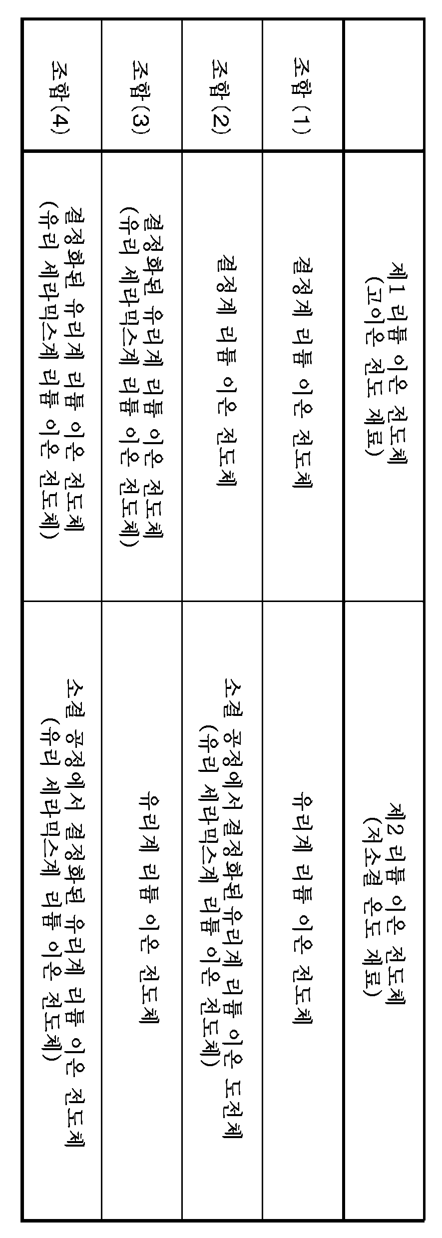
제1 실시 형태에서는, 제1 리튬 이온 전도체의 소결 온도가 600℃를 초과하고 1100℃ 이하인 경우를 예로서 설명했지만, 제1 리튬 이온 전도체의 소결 온도가 600℃ 이하여도 된다. 소결 온도가 600℃ 이하인 제1 리튬 이온 전도체로서는, 결정화된 제2 리튬 이온 전도체, 즉 결정화된 산화물 유리계 리튬 이온 전도체를 사용해도 된다. 결정화된 산화물 유리계 리튬 이온 전도체는, 계면 저항이 높고 이온 전도도가 낮기 때문에, 결정화된 산화물 유리계 리튬 이온 전도체의 사이를, 소결된 제2 리튬 이온 전도체에 의해 물리적으로 또한 이온 전도적으로 연결함으로써, 높은 리튬 이온 전도성이 얻어진다.In the first embodiment, the case where the sintering temperature of the first lithium ion conductor is more than 600 DEG C but not more than 1100 DEG C has been described as an example, but the sintering temperature of the first lithium ion conductor may be 600 DEG C or less. As the first lithium ion conductor having a sintering temperature of 600 ° C or less, a crystallized second lithium ion conductor, that is, a crystallized oxide glass based lithium ion conductor may be used. Since the crystallized oxide glass-based lithium ion conductor has high interface resistance and low ion conductivity, the crystallized oxide glass-based lithium ion conductor is physically and ionically conductively connected by the sintered second lithium ion conductor , High lithium ion conductivity is obtained.
<2 제2 실시 형태>≪ 2 < Second Embodiment >
제2 실시 형태에서는, 상술의 제1 실시 형태에 따른 리튬 이온 전도체의 소결체를 고체 전해질로 하여 정극, 부극 및 고체 전해질층에 포함하는 전지에 대하여 설명한다. 여기에서는, 리튬 이온 전도체의 소결체란, 리튬 이온 전도체에 포함되는 제1, 제2 리튬 이온 전도체 중 제2 리튬 이온 전도체가 소결되어 있음을 의미하고 있다.In the second embodiment, a battery including a positive electrode, a negative electrode, and a solid electrolyte layer using the solid electrolyte as the sintered body of the lithium ion conductor according to the first embodiment will be described. Here, the sintered body of the lithium ion conductor means that the second lithium ion conductor of the first and second lithium ion conductors included in the lithium ion conductor is sintered.
[2.1 전지의 구성][2.1 Configuration of Battery]
본 기술의 제2 실시 형태에 따른 전지는, 소위 벌크형 전고체 전지이고, 도 2의 A에 도시한 바와 같이, 정극(11)과 부극(12)과 고체 전해질층(13)을 구비하고, 고체 전해질층(13)은 정극(11)과 부극(12) 사이에 설치되어 있다. 이 전지는, 전극 반응 물질인 Li의 수수에 의해 전지 용량이 반복하여 얻어지는 이차 전지이고, 리튬 이온의 흡장 방출에 의해 부극의 용량이 얻어지는 리튬 이온 이차 전지여도 되고, 리튬 금속의 석출 용해에 의해 부극의 용량이 얻어지는 리튬 금속 이차 전지여도 된다.The battery according to the second embodiment of the present technology is a so-called bulk-type all solid-state battery and has a positive electrode 11, a negative electrode 12 and a
(정극)(Positive electrode)
정극(11)은 1종 또는 2종류 이상의 정극 활물질과, 고체 전해질을 포함하고 있는 정극 활물질층이다. 고체 전해질이, 결착제로서의 기능을 갖고 있어도 된다. 정극(11)은 필요에 따라 도전제를 더 포함하고 있어도 된다. 정극(11)은, 예를 들면 정극 전구체로서의 그린 시트(이하 「정극 그린 시트」라고 함)의 소성체이다.The positive electrode 11 is a positive electrode active material layer containing one or more kinds of positive electrode active material and a solid electrolyte. The solid electrolyte may have a function as a binder. The positive electrode 11 may further include a conductive agent if necessary. The positive electrode 11 is a sintered body of, for example, a green sheet (hereinafter referred to as " positive electrode green sheet ") as a positive electrode precursor.
정극 활물질은, 예를 들어 전극 반응 물질인 리튬 이온을 흡장 방출 가능한 정극 재료를 포함하고 있다. 이 정극 재료는, 높은 에너지 밀도가 얻어지는 관점에서, 리튬 함유 화합물 등인 것이 바람직하지만, 이것으로 한정되는 것은 아니다. 이 리튬 함유 화합물은, 예를 들어 리튬과 전이 금속 원소를 구성 원소로서 포함하는 복합 산화물(리튬 전이 금속 복합 산화물)이나, 리튬과 전이 금속 원소를 구성 원소로서 포함하는 인산 화합물(리튬 전이 금속 인산 화합물) 등이다. 그 중에서도, 전이 금속 원소는 Co, Ni, Mn 및 Fe 중 어느 1종류 또는 2종류 이상인 것이 바람직하다. 보다 높은 전압이 얻어지기 때문이다.The positive electrode active material includes, for example, a positive electrode material capable of absorbing and desorbing lithium ions, which are electrode reaction materials. The positive electrode material is preferably a lithium-containing compound or the like from the viewpoint of obtaining a high energy density, but is not limited thereto. The lithium-containing compound is, for example, a composite oxide (lithium transition metal composite oxide) containing lithium and a transition metal element as constituent elements, a phosphate compound containing lithium and a transition metal element as constituent elements (lithium transition metal phosphate ). Among them, the transition metal element is preferably at least one of Co, Ni, Mn and Fe, or two or more kinds thereof. A higher voltage is obtained.
리튬 전이 금속 복합 산화물은, 예를 들어 LixM1O2 또는 LiyM2O4 등으로 표시되는 것이다. 보다 구체적으로는 예를 들어, 리튬 전이 금속 복합 산화물은 LiCoO2, LiNiO2, LiVO2, LiCrO2 또는 LiMn2O4 등이다. 또한, 리튬 전이 금속 인산 화합물은, 예를 들어 LizM3PO4 등으로 표시되는 것이다. 보다 구체적으로는 예를 들면, 리튬 전이 금속 인산 화합물은 LiFePO4 또는 LiCoPO4 등이다. 단, M1 내지 M3은 1종류 또는 2종류 이상의 전이 금속 원소이고, x 내지 z의 값은 임의이다.The lithium-transition metal composite oxide is represented by, for example, Li x M 1 O 2 or Li y M 2 O 4 . More specifically, for example, the lithium-transition metal composite oxide is LiCoO 2 , LiNiO 2 , LiVO 2 , LiCrO 2, or LiMn 2 O 4 . Further, the lithium transition metal phosphate compound is, for example, Li z M 3 PO 4 And so on. More specifically, for example, the lithium transition metal phosphate compound is LiFePO 4 or LiCoPO 4 . However, M1 to M3 are one kind or two or more kinds of transition metal elements, and values of x to z are arbitrary.
이밖에, 정극 활물질은, 예를 들어 산화물, 이황화물, 칼코겐화물 또는 도전성 고분자 등이어도 된다. 산화물은, 예를 들어 산화티타늄, 산화바나듐 또는 이산화망간 등이다. 이황화물은, 예를 들어 이황화티타늄 또는 황화몰리브덴 등이다. 칼코겐화물은, 예를 들어 셀렌화니오븀 등이다. 도전성 고분자는, 예를 들어 황, 폴리아닐린 또는 폴리티오펜 등이다.In addition, the positive electrode active material may be, for example, an oxide, a disulfide, a chalcogenide, or a conductive polymer. The oxide is, for example, titanium oxide, vanadium oxide or manganese dioxide. The disulfide is, for example, titanium disulfide or molybdenum sulfide. The chalcogenide is, for example, niobium selenide. The conductive polymer is, for example, sulfur, polyaniline or polythiophene.
정극 활물질은, 정극 활물질 입자의 분말이다. 정극 활물질 입자의 표면이 피복제에 의해 피복되어 있어도 된다. 여기서, 피복은 정극 활물질 입자의 표면 전체에 한정되는 것은 아니고, 정극 활물질 입자의 표면 일부여도 된다. 피복제는, 예를 들어 고체 전해질 및 도전제 중 적어도 1종이다. 정극 활물질 입자의 표면을 피복제로 피복함으로써, 정극 활물질 입자와 고체 전해질의 계면 저항을 저감할 수 있다. 또한, 정극 활물질 입자의 구조 붕괴를 억제할 수 있으므로, 소인 전위 폭을 확장하여, 많은 리튬을 반응에 사용할 수 있게 됨과 동시에, 사이클 특성도 향상시킬 수 있다.The positive electrode active material is a powder of positive electrode active material particles. The surface of the positive electrode active material particles may be covered with a coating agent. Here, the coating is not limited to the entire surface of the positive electrode active material particle but may be a part of the surface of the positive electrode active material particle. The coating agent is, for example, at least one of a solid electrolyte and a conductive agent. By coating the surface of the positive electrode active material particles with a coating agent, the interface resistance between the positive electrode active material particles and the solid electrolyte can be reduced. In addition, since structural collapse of the positive electrode active material particles can be suppressed, a large sweeping potential width can be extended, and a large amount of lithium can be used for the reaction and the cycle characteristics can be improved.
고체 전해질은, 상술한 제1 실시 형태에 따른 리튬 이온 전도체의 소결체이다. 또한, 상기 정극 활물질 입자의 피복제로서의 고체 전해질도, 상술의 제1 실시 형태에 따른 리튬 이온 전도체의 소결체여도 된다.The solid electrolyte is a sintered body of the lithium ion conductor according to the first embodiment. The solid electrolyte as the coating material of the positive electrode active material particles may be a sintered body of the lithium ion conductor according to the first embodiment.
도전제는, 예를 들어 탄소 재료, 금속, 금속 산화물 및 도전성 고분자 등을 단독으로 또는 2종 이상 포함하고 있다. 탄소 재료로서는, 예를 들어 흑연, 탄소 섬유, 카본 블랙 및 카본 나노 튜브 등을 단독으로 또는 2종 이상 조합하여 사용할 수 있다. 탄소 섬유로서는, 예를 들어 기상 성장 탄소 섬유(Vapor Growth Carbon Fiber: VGCF) 등을 사용할 수 있다. 카본 블랙으로서는, 예를 들어 아세틸렌 블랙, 케첸 블랙 등을 사용할 수 있다. 카본 나노 튜브로서는, 예를 들어 싱글 월 카본 나노 튜브(SWCNT), 더블 월 카본 나노 튜브(DWCNT) 등의 멀티 월 카본 나노 튜브(MWCNT) 등을 사용할 수 있다. 금속으로서는, 예를 들어 Ni 분말 등을 사용할 수 있다. 금속 산화물로서는, 예를 들어 SnO2 등을 사용할 수 있다. 도전성 고분자로서는, 예를 들어 치환 또는 비치환된 폴리아닐린, 폴리피롤, 폴리티오펜 및 이것들로부터 선택되는 1종 또는 2종을 포함하는 (공)중합체 등을 사용할 수 있다. 또한, 도전제는, 도전성을 갖는 재료이면 되고, 상술한 예에 한정되는 것은 아니다.The conductive agent includes, for example, a carbon material, a metal, a metal oxide and a conductive polymer, either singly or in combination. As the carbon material, for example, graphite, carbon fiber, carbon black and carbon nanotube may be used alone or in combination of two or more. As the carbon fiber, for example, vapor grown carbon fiber (VGCF) or the like can be used. As the carbon black, for example, acetylene black, ketjen black and the like can be used. As the carbon nanotube, for example, a multiwall carbon nanotube (MWCNT) such as a single wall carbon nanotube (SWCNT) or a double wall carbon nanotube (DWCNT) can be used. As the metal, for example, Ni powder and the like can be used. As the metal oxide, for example, SnO 2 or the like can be used. As the conductive polymer, for example, substituted or unsubstituted polyaniline, polypyrrole, polythiophene, and (co) polymer containing one or two selected from these may be used. The conductive agent may be a conductive material, and is not limited to the above examples.
(부극)(Negative electrode)
부극(12)은 1종 또는 2종류 이상의 부극 활물질과, 고체 전해질을 포함하고 있는 부극 활물질층이다. 고체 전해질이, 결착제로서의 기능을 갖고 있어도 된다. 부극(12)은 필요에 따라 도전제를 더 포함하고 있어도 된다. 부극(12)은, 예를 들어 부극 전구체로서의 그린 시트(이하 「부극 그린 시트」라고 함)의 소성체이다.The negative electrode 12 is a negative electrode active material layer containing one or more negative electrode active materials and a solid electrolyte. The solid electrolyte may have a function as a binder. The negative electrode 12 may further include a conductive agent if necessary. The negative electrode 12 is a sintered body of, for example, a green sheet (hereinafter referred to as negative electrode green sheet) as a negative electrode precursor.
부극 활물질은, 예를 들어 전극 반응 물질인 리튬 이온을 흡장 방출 가능한 부극 재료를 포함하고 있다. 이 부극 재료는, 높은 에너지 밀도가 얻어지는 관점에서, 탄소 재료 또는 금속계 재료 등인 것이 바람직하지만, 이것으로 한정되는 것은 아니다.The negative electrode active material includes, for example, a negative electrode material capable of absorbing and desorbing lithium ions, which are electrode reaction materials. The negative electrode material is preferably a carbon material or a metal material in view of obtaining a high energy density, but is not limited thereto.
탄소 재료는, 예를 들어 이흑연화성 탄소, 난흑연화성 탄소, 흑연, 메소카본 마이크로비드(MCMB) 또는 고배향성 그래파이트(HOPG) 등이다.The carbon material is, for example, graphitizable carbon, hard graphitizable carbon, graphite, mesocarbon microbead (MCMB) or highly oriented graphite (HOPG).
금속계 재료는, 예를 들어 리튬과 합금을 형성 가능한 금속 원소 또는 반금속 원소를 구성 원소로서 포함하는 재료이다. 보다 구체적으로는, 금속계 재료는 예를 들어 Si, Sn, Al, In, Mg, B, Ga, Ge, Pb, Bi, Cd(카드뮴), Ag, Zn, Hf, Zr, Y, Pd(팔라듐) 또는 Pt(백금) 등의 단체, 합금 또는 화합물 중 어느 1종류 또는 2종류 이상이다. 단, 단체는, 순도 100%에 한하지 않고, 미량의 불순물을 포함하고 있어도 된다. 금속계 재료의 구체예로서는 Si, Sn, SiB4, TiSi2, SiC, Si3N4, SiOv(0<v≤2), LiSiO, SnOw(0<w≤2), SnSiO3, LiSnO, Mg2Sn 등을 들 수 있다.The metal-based material is, for example, a material containing a metal element or a semimetal element capable of forming an alloy with lithium as a constituent element. More specifically, the metal-based material includes, for example, Si, Sn, Al, In, Mg, B, Ga, Ge, Pb, Bi, Cd, Ag, Zn, Hf, Zr, Y, Pd Or Pt (platinum), an alloy, or a compound. However, the group may not contain 100% purity and may contain a small amount of impurities. Specific examples of the metal-based material include Si, Sn, SiB 4 , TiSi 2 , SiC, Si 3 N 4 , SiO v (0 < v ≤ 2), LiSiO, SnO w (0 <w ≤ 2), SnSiO 3 , LiSnO, Mg 2 Sn and the like.
금속계 재료는, 리튬 함유 화합물 또는 리튬 금속(리튬의 단체)이어도 된다. 리튬 함유 화합물은, 리튬과 전이 금속 원소를 구성 원소로서 포함하는 복합 산화물(리튬 전이 금속 복합 산화물)이다. 이 복합 산화물로서는, 예를 들어 Li4Ti5O12 등을 들 수 있다.The metallic material may be a lithium-containing compound or a lithium metal (a single lithium). The lithium-containing compound is a composite oxide (lithium-transition metal composite oxide) containing lithium and a transition metal element as constituent elements. Examples of the composite oxide include Li 4 Ti 5 O 12 and the like.
부극 활물질은, 부극 활물질 입자의 분말이다. 부극 활물질 입자의 표면이 피복제로 피복되어 있어도 된다. 여기서, 피복은 부극 활물질 입자의 표면 전체에 한정되는 것은 아니고, 부극 활물질 입자의 표면 일부여도 된다. 피복제는, 예를 들어 고체 전해질 및 도전제 중 적어도 1종이다. 부극 활물질 입자의 표면을 피복제로 피복함으로써, 부극 활물질 입자와 고체 전해질의 계면 저항을 저감할 수 있다. 또한, 부극 활물질 입자의 구조 붕괴를 억제할 수 있으므로, 소인 전위 폭을 확장하여, 많은 리튬을 반응에 사용할 수 있음과 동시에, 사이클 특성도 향상시킬 수 있다.The negative electrode active material is a powder of negative electrode active material particles. The surface of the negative electrode active material particles may be coated with a coating agent. Here, the coating is not limited to the entire surface of the negative electrode active material particle but may be a part of the surface of the negative electrode active material particle. The coating agent is, for example, at least one of a solid electrolyte and a conductive agent. By coating the surface of the negative electrode active material particles with a coating agent, the interface resistance between the negative electrode active material particle and the solid electrolyte can be reduced. Further, since structural collapse of the negative electrode active material particles can be suppressed, a large sweeping potential width can be extended, and a large amount of lithium can be used for the reaction, and the cycle characteristics can be improved.
고체 전해질은, 상술의 제1 실시 형태에 따른 리튬 이온 전도체의 소결체이다. 또한, 상기 부극 활물질 입자의 피복제로서의 고체 전해질도, 상술의 제1 실시 형태에 따른 리튬 이온 전도체의 소결체여도 된다.The solid electrolyte is a sintered body of the lithium ion conductor according to the first embodiment. The solid electrolyte as the coating material of the negative electrode active material particles may also be a sintered body of the lithium ion conductor according to the first embodiment.
도전제는, 상술한 정극(11)에 있어서의 도전제와 마찬가지이다.The conductive agent is the same as the conductive agent in the positive electrode 11 described above.
(고체 전해질층)(Solid electrolyte layer)
고체 전해질층(13)은 상술의 제1 실시 형태에 따른 리튬 이온 전도체의 소결체를 포함하고 있다. 고체 전해질층(13)은, 예를 들어 고체 전해질층 전구체로서의 그린 시트(이하 「고체 전해질 그린 시트」라고 함)의 소성체이다.The
[2.2 전지의 동작][2.2 Operation of Battery]
이 전지에서는, 예를 들어 충전 시에 있어서, 정극(11)으로부터 방출된 리튬 이온이 고체 전해질층(13)을 개재하여 부극(12)에 도입됨과 동시에, 방전 시에 있어서, 부극(12)으로부터 방출된 리튬 이온이 고체 전해질층(13)을 개재하여 정극(11)에 도입된다.In this battery, for example, lithium ions discharged from the positive electrode 11 are introduced into the negative electrode 12 via the
[2.3 전지의 제조 방법][2.3 Manufacturing method of battery]
이어서, 본 기술의 제2 실시 형태에 따른 전지의 제조 방법 일례에 대하여 설명한다. 이 제조 방법은 정극 전구체, 부극 전구체 및 고체 전해질층 전구체를 형성하는 공정과, 이들 전구체를 적층하여 소성하는 공정을 구비한다. 또한, 이 전지의 제조 방법에서는, 정극 전구체, 부극 전구체 및 고체 전해질층 전구체가 모두, 제1 실시 형태에 따른 리튬 이온 전도체를 포함하고 있는 경우를 예로서 설명한다.Next, an example of a manufacturing method of a battery according to a second embodiment of the present technology will be described. This manufacturing method includes a step of forming a positive electrode precursor, a negative electrode precursor and a solid electrolyte layer precursor, and a step of laminating and baking these precursors. The production method of this battery will be described by taking as an example a case where the positive electrode precursor, the negative electrode precursor and the solid electrolyte layer precursor both include the lithium ion conductor according to the first embodiment.
(정극 전구체의 형성 공정)(Step of Forming Positive Electrode Precursor)
정극 전구체로서의 정극 그린 시트를 다음과 같이 하여 형성한다. 먼저, 정극 활물질과, 제1 실시 형태에 따른 리튬 이온 전도체(고체 전해질)와, 유기계 결착제와, 필요에 따라 도전제를 혼합하여, 원료 분말로서의 정극합제 분말을 제조한 뒤, 이 정극합제 분말을 유기 용제 등에 분산시켜, 정극 그린 시트 형성용 조성물로서의 정극 슬러리를 얻는다. 또한, 정극합제 분말의 분산성을 향상시키기 위해서, 분산을 수회로 나누어서 행해도 된다.A positive electrode green sheet as a positive electrode precursor is formed as follows. First, the positive electrode active material, the lithium ion conductor (solid electrolyte) according to the first embodiment, the organic binder and, if necessary, the conductive agent are mixed to prepare a positive electrode material mixture powder as a raw material powder, Is dispersed in an organic solvent or the like to obtain a positive electrode slurry as a composition for forming a positive electrode green sheet. Further, in order to improve the dispersibility of the positive electrode material mixture powder, dispersion may be performed in several steps.
유기계 결착제로서는, 예를 들어 아크릴 수지 등의 유기 결착제를 사용할 수 있다. 용매로서는, 정극합제 분말을 분산할 수 있는 것이라면 특별히 한정되지 않지만, 그린 시트의 소성 온도보다도 낮은 온도 영역에서 소실하는 것이 바람직하다. 용매로서는, 예를 들어 메탄올, 에탄올, 이소프로판올, n-부탄올, sec-부탄올, t-부탄올 등의 탄소수가 4 이하의 저급 알코올, 에틸렌글리콜, 프로필렌글리콜(1,3-프로판디올), 1,3-프로판디올, 1,4-부탄디올, 1,2-부탄디올, 1,3-부탄디올, 2-메틸-1,3-프로판디올 등의 지방족 글리콜, 메틸에틸케톤 등의 케톤류, 디메틸에틸아민 등의 아민류, 테르피네올 등의 지환족 알코올 등을 단독 또는 2종 이상 혼합하여 사용할 수 있지만, 특별히 이것으로 한정되는 것은 아니다. 분산 방법으로서는, 예를 들어 교반 처리, 초음파 분산 처리, 비즈 분산 처리, 혼련 처리, 균질기 처리 등을 들 수 있다.As the organic binder, for example, an organic binder such as an acrylic resin can be used. The solvent is not particularly limited as long as it can disperse the positive electrode material mixture powder, but it is preferable that the solvent disappear in a temperature range lower than the firing temperature of the green sheet. Examples of the solvent include lower alcohols having 4 or less carbon atoms such as methanol, ethanol, isopropanol, n-butanol, sec-butanol and t-butanol, ethylene glycol, propylene glycol (1,3-propanediol) Aliphatic glycols such as propanediol, 1,4-butanediol, 1,2-butanediol, 1,3-butanediol and 2-methyl-1,3-propanediol, ketones such as methyl ethyl ketone, amines such as dimethylethylamine Alicyclic alcohols such as terpineol, and the like can be used alone or in admixture of two or more, but the present invention is not limited thereto. Examples of the dispersion method include stirring treatment, ultrasonic dispersion treatment, bead dispersion treatment, kneading treatment, homogenizer treatment, and the like.
이어서, 필요에 따라, 필터에 의해 정극 슬러리를 여과하고, 정극 슬러리 중의 이물을 제거하게 해도 된다. 이어서, 필요에 따라, 정극 슬러리에 대하여, 내부의 기포를 제거하기 위한 진공 탈포를 행하게 해도 된다.Subsequently, if necessary, the positive electrode slurry may be filtered by a filter to remove foreign matter in the positive electrode slurry. Subsequently, if necessary, the negative electrode slurry may be subjected to vacuum defoaming to remove air bubbles therein.
다음으로, 예를 들어 지지 기재의 표면에 정극 슬러리를 균일하게 도포 또는 인쇄함으로써, 정극 슬러리층을 성형한다. 지지 기체로서는, 예를 들어 폴리에틸렌테레프탈레이트(PET) 등의 고분자 수지 필름 등을 사용할 수 있다. 도포 또는 인쇄의 방법으로서는, 간편하고 양산성에 적합한 방법을 사용하는 것이 바람직하다. 도포 방법으로서는, 예를 들어, 다이 코팅법, 마이크로 그라비아 코팅법, 와이어 바 코팅법, 다이렉트 그라비아 코팅법, 리버스 롤 코팅법, 콤마 코팅법, 나이프 코팅법, 스프레이 코팅법, 커튼 코팅법, 침지법, 스핀 코팅법 등을 사용할 수 있지만, 특별히 이것으로 한정되는 것은 아니다. 인쇄 방법으로서는, 예를 들어 철판 인쇄법, 오프셋 인쇄법, 그라비아 인쇄법, 요판 인쇄법, 고무판 인쇄법, 스크린 인쇄법 등을 사용할 수 있지만, 특별히 이것으로 한정되는 것은 아니다.Next, the positive electrode slurry layer is formed, for example, by uniformly applying or printing the positive electrode slurry on the surface of the supporting substrate. As the supporting base, for example, a polymer resin film such as polyethylene terephthalate (PET) or the like can be used. As a method of coating or printing, it is preferable to use a method which is simple and suitable for mass production. Examples of the application method include a die coating method, a micro gravure coating method, a wire bar coating method, a direct gravure coating method, a reverse roll coating method, a comma coating method, a knife coating method, a curtain coating method, , A spin coating method, and the like can be used, but the present invention is not limited thereto. As the printing method, for example, an iron plate printing method, an offset printing method, a gravure printing method, an intaglio printing method, a rubber plate printing method, a screen printing method and the like can be used.
후속 공정에서 정극 그린 시트를 지지 기재의 표면으로부터 박리하기 쉽게 하기 위해서, 지지 기재의 표면에 박리 처리를 미리 실시해 두는 것이 바람직하다. 박리 처리로서는, 예를 들어 박리성을 부여하는 조성물을 지지 기재의 표면에 미리 도포 또는 인쇄하는 방법을 들 수 있다. 박리성을 부여하는 조성물로서는, 예를 들어 바인더를 주성분으로 하고, 왁스나 불소 등이 첨가된 도료 또는 실리콘 수지 등을 들 수 있다.It is preferable that the surface of the supporting substrate is subjected to the peeling treatment in advance in order to facilitate peeling of the positive electrode green sheet from the surface of the supporting substrate in the subsequent step. As the peeling treatment, for example, a method of previously applying or printing a composition for imparting releasability to the surface of the supporting substrate may be mentioned. As the composition for imparting releasability, for example, a paint containing a binder as a main component and to which wax, fluorine or the like is added, or a silicone resin may, for example, be mentioned.
이어서, 정극 슬러리층을 건조시킴으로써, 지지 기재의 표면에 정극 그린 시트를 형성한다. 건조 방법으로서는, 예를 들어 자연 건조, 열풍 등에 의한 송풍 건조, 적외선이나 원적외선 등에 의한 가열 건조, 진공 건조 등을 들 수 있다. 이들 건조 방법을 단독으로 사용해도 되고, 2 이상 조합하여 사용해도 된다.Subsequently, the positive electrode slurry layer is dried to form a positive electrode green sheet on the surface of the supporting substrate. Examples of the drying method include natural drying, air blow drying by hot air, heating drying by infrared rays or far infrared rays, vacuum drying, and the like. These drying methods may be used alone or in combination of two or more.
(부극 전구체의 형성 공정)(Step of forming negative electrode precursor)
부극 전구체로서의 부극 그린 시트를 다음과 같이 하여 형성한다. 먼저, 부극 활물질과, 제1 실시 형태에 따른 리튬 이온 전도체(고체 전해질)와, 유기계 결착제와, 필요에 따라 도전제를 혼합하여, 원료 분말로서의 부극합제 분말을 제조한 뒤, 이 부극합제 분말을 유기 용제 등에 분산시켜, 부극 그린 시트 형성용 조성물로서의 부극 슬러리를 얻는다. 이 부극 슬러리를 사용하는 것 이외에는 상술한 「정극 전구체의 형성 공정」과 동일하게 하여, 부극 그린 시트를 얻는다.A negative electrode green sheet as a negative electrode precursor is formed as follows. First, a negative electrode active material, a lithium ion conductor (solid electrolyte) according to the first embodiment, an organic binder and, if necessary, a conductive agent are mixed to prepare a negative electrode material mixture powder as a raw material powder, Is dispersed in an organic solvent or the like to obtain a negative electrode slurry as a composition for forming a negative electrode green sheet. A positive electrode green sheet is obtained in the same manner as the above-described " positive electrode precursor forming step " except that the negative electrode slurry is used.
(고체 전해질 전구체의 형성 공정)(Formation process of solid electrolyte precursor)
고체 전해질층 전구체로서의 고체 전해질 그린 시트를 다음과 같이 하여 형성한다. 먼저, 제1 실시 형태에 따른 리튬 이온 전도체(고체 전해질)와, 유기계 결착제를 혼합하여, 원료 분말로서의 전해질 합제 분말을 제조한 뒤, 이 전해질 합제 분말을 유기 용제 등에 분산시켜, 고체 전해질 그린 시트 형성용 조성물로서의 전해질 합제 슬러리를 얻는다. 이 전해질 합제 슬러리를 사용하는 것 이외에는 상술한 「정극 전구체의 형성 공정」과 동일하게 하여, 고체 전해질 그린 시트를 얻는다.A solid electrolyte green sheet as a solid electrolyte layer precursor is formed as follows. First, a lithium ion conductor (solid electrolyte) according to the first embodiment is mixed with an organic binder to prepare an electrolyte mixture powder as a raw material powder. Then, the electrolyte mixture powder is dispersed in an organic solvent or the like to form a solid electrolyte green sheet To obtain an electrolyte mixture slurry as a composition for forming an electrolyte. A solid electrolyte green sheet is obtained in the same manner as the " positive electrode precursor forming step " except that the electrolyte mixture slurry is used.
(전구체의 적층 및 소성 공정)(Laminating and firing steps of the precursor)
상술한 바와 같이 하여 얻어진 정극 그린 시트, 부극 그린 시트 및 고체 전해질 그린 시트를 사용하여, 다음과 같이 하여 전지를 제조한다. 먼저, 고체 전해질 그린 시트를 사이에 두도록 정극 그린 시트와 부극 그린 시트를 적층하여 적층체로 한다. 그 후, 적층체를 가열하는 동시에, 적어도 적층체의 두께 방향으로 압력이 가해지도록 적층체를 프레스한다. 이에 의해, 적층체를 구성하는 각 그린 시트에 포함되는 유기계 결착제가 용융됨과 함께, 적층체를 구성하는 각 그린 시트 사이가 밀착된다. 적층체를 가열하면서 프레스하는 구체적인 방법으로서는, 예를 들어 핫 프레스법, 온간 등방압 프레스(Warm Isostatic Press: WIP) 등을 들 수 있다.A positive electrode green sheet, a negative electrode green sheet and a solid electrolyte green sheet obtained as described above were used to produce a battery as follows. First, a positive electrode green sheet and a negative electrode green sheet are laminated to form a laminate so that the solid electrolyte green sheet is sandwiched therebetween. Thereafter, the laminate is heated while pressing the laminate so that at least pressure is applied in the thickness direction of the laminate. As a result, the organic binder contained in each of the green sheets constituting the laminate is melted and the green sheets constituting the laminate are closely contacted with each other. As a specific method of pressing the laminate while heating, for example, a hot press method, a warm isostatic press (WIP) and the like can be given.
이어서, 필요에 따라 적층체를 소정의 크기 및 형상으로 절단한다. 이어서, 적층체를 소성함으로써, 적층체를 구성하는 각 그린 시트 중에 포함되는 리튬 이온 전도체를 소결시킴과 함께, 유기계 결착제를 소실시킨다.Then, the laminate is cut into a predetermined size and shape as necessary. Subsequently, the laminate is sintered to sinter the lithium ion conductor contained in each green sheet constituting the laminate, and the organic binder is destroyed.
적층체의 소성 온도는, 바람직하게는 제2 리튬 이온 전도체의 소결 온도 이상 600℃ 이하, 보다 바람직하게는 제2 리튬 이온 전도체의 소결 온도 이상 500℃ 이하이다. 여기서, 제2 리튬 이온 전도체의 소결 온도란, 적층체에 포함되는 리튬 이온 전도체가 1종류인 경우에는, 그 제2 리튬 이온 전도체의 소결 온도를 의미한다. 이에 비해, 적층체에 포함되는 제2 리튬 이온 전도체가 2종 이상인 경우에는, 그 제2 리튬 이온 전도체들의 소결 온도 중 최대의 것을 의미한다.The firing temperature of the laminate is preferably not less than the sintering temperature of the second lithium ion conductor of not more than 600 캜, more preferably not less than 500 캜 of the sintering temperature of the second lithium ion conductor. Here, the sintering temperature of the second lithium ion conductor means the sintering temperature of the second lithium ion conductor when one type of lithium ion conductor is included in the laminate. In contrast, when the number of the second lithium ion conductors included in the laminate is two or more, it means the largest sintering temperature of the second lithium ion conductors.
적층체의 소성 온도가 제2 리튬 이온 전도체의 소결 온도 이상이면, 제2 리튬 이온 전도체의 소결이 진행하므로, 정극, 부극 및 고체 전해질층의 리튬 이온 전도성을 향상시킬 수 있다. 또한, 정극, 부극 및 고체 전해질층의 강도를 높일 수 있다. 적층체의 소성 온도를 600℃ 이하 또는 500℃ 이하로 하는 이유는, 제1 실시 형태에 있어서 설명한 리튬 이온 전도체의 소결 온도를 600℃ 이하 또는 500℃ 이하로 하는 이유와 마찬가지이다.When the sintering temperature of the laminate is not lower than the sintering temperature of the second lithium ion conductor, sintering of the second lithium ion conductor proceeds, so that the lithium ion conductivity of the positive electrode, the negative electrode and the solid electrolyte layer can be improved. Further, the strength of the positive electrode, the negative electrode, and the solid electrolyte layer can be increased. The reason why the firing temperature of the laminate is set to 600 占 폚 or less or 500 占 폚 or less is the same as the reason for setting the sintering temperature of the lithium ion conductor described in the first embodiment to 600 占 폚 or less or 500 占 폚 or less.
제2 리튬 이온 전도체가 산화물 유리계 리튬 이온 전도체를 포함하고 있는 경우에는, 소성 공정에 있어서 산화물 유리계 리튬 이온 전도체를 유리화하여, 산화물 유리 세라믹스계 리튬 이온 전도체로 해도 된다. 이상에 의해, 목적으로 하는 전지가 얻어진다.When the second lithium ion conductor contains an oxide glass-based lithium ion conductor, the oxide glass-based lithium ion conductor may be vitrified in the firing step to form an oxide-glass-ceramics-based lithium ion conductor. As a result of the above, a target battery can be obtained.
[2.4 효과][2.4 Effects]
본 기술의 제2 실시 형태에서는 정극 그린 시트, 부극 그린 시트 및 고체 전해질 그린 시트에 포함되는 고체 전해질이, 제1 실시 형태에 따른 리튬 이온 전도체, 즉 저온 소결 가능한 리튬 이온 전도체이다. 따라서, 정극 그린 시트, 부극 그린 시트 및 고체 전해질 그린 시트의 소성 온도를 저온으로 할 수 있다. 이에 의해, 적층체의 소성 공정에 있어서의 정극 활물질 및 부극 활물질의 대미지를 억제하고, 전지 특성의 저하를 억제할 수 있다. 또한, 정극 활물질 및 부극 활물질의 종류 선택 폭이 넓어지고, 전지 설계의 자유도가 향상된다.In the second embodiment of the present technology, the solid electrolyte contained in the positive electrode green sheet, the negative electrode green sheet and the solid electrolyte green sheet is the lithium ion conductor according to the first embodiment, that is, the lithium ion conductor capable of low temperature sintering. Therefore, the sintering temperature of the positive electrode green sheet, negative electrode green sheet and solid electrolyte green sheet can be lowered. Thereby, the damage of the positive electrode active material and the negative electrode active material in the firing step of the laminate can be suppressed, and deterioration of the battery characteristics can be suppressed. Further, the selection range of the types of the positive electrode active material and the negative electrode active material is widened, and the degree of freedom of the battery design is improved.
정극 그린 시트, 부극 그린 시트 및 고체 전해 그린 시트를 저온에서 일괄 소성하여 전고체 전지를 제조할 수 있다. 따라서, 소성에 의한 정극(11), 부극(12) 및 고체 전해질층(13)에 대한 대미지를 억제하면서, 정극(11)과 고체 전해질층(13) 사이의 계면 저항, 및 부극(12)과 고체 전해질층(13) 사이의 계면 저항을 낮출 수 있다.The positive electrode green sheet, the negative electrode green sheet and the solid electrolytic green sheet can be collectively fired at a low temperature to produce an all solid battery. Therefore, the interface resistance between the positive electrode 11 and the
정극(11) 및 부극(12) 내에서, 제1 실시 형태에 따른 리튬 이온 전도체가 소결되어 있기 때문에, 정극(11) 및 부극(12)의 막 강도가 높다. 따라서, 정극(11) 및 부극(12)의 층 두께를 두껍게 한 경우에도, 전지 성능을 유지할 수 있다.Since the lithium ion conductor according to the first embodiment is sintered in the positive electrode 11 and the negative electrode 12, the film strength of the positive electrode 11 and the negative electrode 12 is high. Therefore, even when the thicknesses of the positive electrode 11 and the negative electrode 12 are increased, battery performance can be maintained.
그린 시트 프로세스를 사용하여 전고체 전지를 제조함으로써, 전지 용량에 기여하지 않는 외장재 등의 부재를 없애거나, 또는 일반적인 원통형, 각형 또는 스택형의 리튬 이온 전지에 비하여 전지 용량에 기여하지 않는 외장재 등의 부재를 저감시킬 수 있다. 따라서, 전지 또는 전지 팩 전체에 대한 정극 활물질 및 부극 활물질의 점유율을 높여, 전지 용량(에너지 밀도)을 향상시킬 수 있다.The entire solid battery is manufactured by using the green sheet process to eliminate members such as exterior materials that do not contribute to the battery capacity or to use a casing material that does not contribute to the battery capacity as compared with a general cylindrical, The member can be reduced. Therefore, it is possible to increase the occupancy rate of the positive electrode active material and the negative electrode active material to the entire battery or the battery pack, thereby improving the battery capacity (energy density).
전해질로서 고체 전해질을 사용하고 있기 때문에, 안전성이 향상된다. 이로 인해, 전지 구조나 제어 회로 등을 간소화할 수 있다. 따라서, 전지의 체적 에너지 밀도 및 중량 에너지 밀도가 향상된다.Since the solid electrolyte is used as the electrolyte, the safety is improved. As a result, the battery structure, the control circuit, and the like can be simplified. Thus, the volume energy density and the weight energy density of the battery are improved.
[2.5 변형예][2.5 Variation Example]
상술한 제2 실시 형태에서는 정극, 부극이 각각 정극 활물질층, 부극 활물질층만에 의해 구성된 예에 대하여 설명했지만, 정극 및 부극의 구성은 이것으로 한정되는 것은 아니다. 예를 들어, 도 2의 B에 도시한 바와 같이, 정극(21)이 정극 집전체(21A)와, 이 정극 집전체(21A)의 한쪽 면에 설치된 정극 활물질층(21B)을 구비하고 있어도 된다. 또한, 부극(22)이 부극 집전체(22A)와, 이 부극 집전체(22A)의 한쪽 면에 설치된 부극 활물질층(22B)을 구비하게 해도 된다. 이 경우, 정극 활물질층(21B)과 부극 활물질층(22B)이 대향하도록, 정극(21)과 부극(22)이 고체 전해질층(13)을 개재하여 적층된다. 또한, 상술한 제2 실시 형태와 동일한 개소에는 동일한 부호를 부여하여 설명을 생략한다.In the second embodiment described above, an example in which the positive electrode and the negative electrode are formed only of the positive electrode active material layer and the negative electrode active material layer has been described. However, the configurations of the positive electrode and the negative electrode are not limited thereto. For example, as shown in Fig. 2B, the positive electrode 21 may include a positive electrode current collector 21A and a positive electrode active material layer 21B provided on one surface of the positive electrode current collector 21A . The negative electrode 22 may include a negative electrode current collector 22A and a negative electrode active material layer 22B provided on one surface of the negative electrode current collector 22A. In this case, the positive electrode 21 and the negative electrode 22 are laminated via the
정극 집전체(21A)는, 예를 들어 Al, Ni, 스테인리스강 등의 금속을 포함하고 있다. 정극 집전체(21A)의 형상은, 예를 들어 박 형상, 판 형상, 메쉬 형상 등이다. 정극 활물질층(21B)은, 제2 실시 형태에 있어서의 정극(정극 활물질층)(11)과 동일하다.The positive electrode current collector 21A includes, for example, metals such as Al, Ni, and stainless steel. The shape of the positive electrode current collector 21A is, for example, a thin shape, a plate shape, a mesh shape, or the like. The positive electrode active material layer 21B is the same as the positive electrode (positive electrode active material layer) 11 in the second embodiment.
부극 집전체(22A)는, 예를 들어 Cu, 스테인리스강 등의 금속을 포함하고 있다. 부극 집전체(22A)의 형상은, 예를 들어 박 형상, 판 형상, 메쉬 형상 등이다. 부극 활물질층(22B)은, 제2 실시 형태에 있어서의 부극(부극 활물질층)(12)과 동일하다.The negative electrode current collector 22A includes, for example, a metal such as Cu or stainless steel. The shape of the anode current collector 22A is, for example, a shape of a thin plate, a plate, or a mesh. The negative electrode active material layer 22B is the same as the negative electrode (negative electrode active material layer) 12 in the second embodiment.
또한, 정극(21) 및 부극(22) 중 한쪽이 집전체와 활물질층을 구비하고, 다른 쪽이 활물질층만을 구비하는 구성으로 해도 된다.One of the positive electrode 21 and the negative electrode 22 may have a current collector and an active material layer, and the other may include only the active material layer.
상술한 제2 실시 형태에서는, 전극 반응 물질로서 리튬을 사용하는 전지에 대하여 본 기술을 적용한 예에 대하여 설명했지만, 본 기술은 이 예에 한정되는 것은 아니다. 전극 반응 물질로서, 예를 들어 Na 또는 K 등의 다른 알칼리 금속, Mg 또는 Ca 등의 알칼리 토금속 또는 Al 또는 Ag 등의 기타 금속을 사용하는 전지에 본 기술을 적용해도 된다.In the second embodiment described above, an example has been described in which the present technology is applied to a battery using lithium as an electrode reaction material, but the present technology is not limited to this example. The present technology may be applied to a battery using, for example, another alkali metal such as Na or K, an alkaline earth metal such as Mg or Ca, or other metals such as Al or Ag as the electrode reacting material.
상술한 제2 실시 형태에서는 정극 전구체, 부극 전구체 및 고체 전해질층 전구체가 그린 시트인 경우를 예로서 설명했지만, 정극 전구체, 부극 전구체 및 고체 전해질층 전구체가 압분체여도 된다. 정극 전구체, 부극 전구체 및 고체 전해질층 전구체 중 1층 또는 2층의 전구체가 그린 시트이고, 나머지가 압분체여도 된다. 정극 전구체로서의 압분체는, 프레스기 등으로 정극합제 분말을 가압 성형함으로써 제조된다. 부극 전구체로서의 압분체는, 프레스기 등으로 부극합제 분말을 가압 성형함으로써 제조된다. 고체 전해질층 전구체로서의 압분체는, 프레스기 등으로 전해질 합제 분말을 가압 성형함으로써 제조된다. 또한, 정극합제 분말, 부극합제 분말 및 전해질 합제 분말은, 유기계 결착제를 포함하고 있지 않아도 된다.In the second embodiment described above, the positive electrode precursor, the negative electrode precursor, and the solid electrolyte layer precursor are green sheets. However, the positive electrode precursor, the negative electrode precursor, and the solid electrolyte layer precursor may be green compacts. One or two precursors of the positive electrode precursor, the negative electrode precursor and the solid electrolyte layer precursor may be a green sheet and the remainder may be a green compact. The green compact as the positive electrode precursor is produced by press-molding the positive electrode mixture powder with a press machine or the like. The green compact as the negative electrode precursor is produced by press-molding the negative electrode mixture powder with a press machine or the like. The green compact as the solid electrolyte layer precursor is produced by press-molding the electrolyte mixture powder with a press machine or the like. In addition, the positive electrode material mixture powder, the negative electrode material mixture powder and the electrolyte mixture powder need not contain the organic binder.
상술한 제2 실시 형태에서는 정극 전구체, 고체 전해질층 전구체 및 부극 전구체를 적층하고 나서 소성하는 예에 대하여 설명했지만, 정극 전구체, 고체 전해질층 전구체 및 부극 전구체를 소성하여 소성체(소결체)로 하고 나서, 이들의 소성체를 적층하여 적층체를 형성해도 된다. 이 경우, 적층체의 프레스 후에 적층체를 소성하지 않아도 되고, 필요에 따라 적층체의 프레스 후에 적층체를 소성하게 해도 된다.In the second embodiment described above, the positive electrode precursor, the solid electrolyte layer precursor, and the negative electrode precursor are stacked and fired. However, the positive electrode precursor, the solid electrolyte layer precursor, and the negative electrode precursor are fired to form a fired body (sintered body) , And the sintered bodies thereof may be laminated to form a laminate. In this case, the laminate may not be baked after the pressing of the laminate, and the laminate may be baked after pressing the laminate if necessary.
정극 전구체, 고체 전해질층 전구체 및 부극 전구체 중 1층 또는 2층의 전구체를 미리 소성하여 소성체(소결체)로 하고, 그 이외의 나머지의 층을 미소성의 전구체로서 두고, 그것들의 소성체와 전구체를 적층하여 적층체를 형성해도 된다. 이 경우, 적층체의 프레스 후에 적층체를 소성하는 것이 바람직하다.The precursor of one or two layers of the positive electrode precursor, the solid electrolyte layer precursor and the negative electrode precursor is previously fired to form a fired body (sintered body), and the other remaining layers are used as the unfilled precursor, and the fired body and the precursor Or may be laminated to form a laminate. In this case, it is preferable to sinter the laminate after the pressing of the laminate.
정극 전구체, 고체 전해질층 전구체 및 부극 전구체 중 2층을 미리 적층하여 소성해 두고, 이 적층체에 나머지의 미소성의 1층을 적층하여 적층체를 형성해도 된다. 이 경우, 적층체의 프레스 후에 적층체를 소성하는 것이 바람직하다.Two layers of the positive electrode precursor, the solid electrolyte layer precursor and the negative electrode precursor may be preliminarily laminated and fired, and the remaining unflavored one layer may be laminated on the laminate to form a laminate. In this case, it is preferable to sinter the laminate after the pressing of the laminate.
정극 전구체, 고체 전해질층 전구체 및 부극 전구체 중 2층의 전구체를 미리 적층하여 소성하는 동시에, 나머지 1층의 전구체를 별도 소성하여 소성체로 해 두고, 그것들을 적층하여 적층체를 형성해도 된다. 이 경우, 적층체의 프레스 후에 적층체를 소성하지 않아도 되고, 필요에 따라 적층체의 프레스 후에 적층체를 소성하게 해도 된다.The two precursors of the positive electrode precursor, the solid electrolyte layer precursor and the negative electrode precursor may be preliminarily laminated and fired, and the remaining one precursor may be separately fired to form a fired body and laminated to form a laminate. In this case, the laminate may not be baked after the pressing of the laminate, and the laminate may be baked after pressing the laminate if necessary.
상술한 제2 실시 형태에서는 정극 전구체, 부극 전구체를 각각 정극 그린 시트, 부극 그린 시트에 의해 형성하는 경우를 예로서 설명했지만, 정극 전구체 및 부극 전구체 중 적어도 한쪽을 이하와 같이 하여 형성해도 된다. 즉, 고체 전해질층 전구체 또는 고체 전해질층의 한쪽 면에 정극 슬러리를 도포 또는 인쇄한 후, 건조시켜서 정극 전구체를 형성하도록 해도 된다. 또한, 고체 전해질층 전구체 또는 고체 전해질층의 다른 쪽의 면에 부극 슬러리를 도포 또는 인쇄한 후, 건조시켜서 부극 전구체를 형성하도록 해도 된다.In the above-described second embodiment, the positive electrode precursor and the negative electrode precursor are formed of a positive electrode green sheet and a negative electrode green sheet, respectively. However, at least one of the positive electrode precursor and the negative electrode precursor may be formed as follows. That is, the positive electrode slurry may be coated or printed on one side of the solid electrolyte layer precursor or the solid electrolyte layer, followed by drying to form the positive electrode precursor. The negative electrode slurry may be coated or printed on the other side of the solid electrolyte layer precursor or the solid electrolyte layer and then dried to form the negative electrode precursor.
상술한 제2 실시 형태에서는 정극, 부극 및 고체 전해질층의 모두가, 제1 실시 형태에 따른 리튬 이온 전도체의 소결체를 고체 전해질로서 포함하고 있는 구성을 예로서 설명했지만, 본 기술은 이 구성에 한정되는 것은 아니다. 예를 들어, 정극, 부극 및 고체 전해질층 중 적어도 1층이 제1 실시 형태에 따른 리튬 이온 전도체의 소결체를 고체 전해질로서 포함하고 있어도 된다. 보다 구체적으로는 예를 들어, 정극, 부극 및 고체 전해질층 중 1층 또는 2층이 제1 실시 형태에 따른 리튬 이온 전도체의 소결체를 고체 전해질로서 포함하고, 그 이외의 나머지의 층이 제1 실시 형태에 따른 리튬 이온 전도체 이외의 리튬 이온 전도체를 고체 전해질로서 포함하게 해도 된다.In the above-described second embodiment, all of the positive electrode, negative electrode, and solid electrolyte layer have been described by way of example in which the sintered body of the lithium ion conductor according to the first embodiment is contained as a solid electrolyte. However, It is not. For example, at least one of the positive electrode, the negative electrode, and the solid electrolyte layer may contain the sintered body of the lithium ion conductor according to the first embodiment as a solid electrolyte. More specifically, for example, one or two layers of the positive electrode, the negative electrode and the solid electrolyte layer contain the sintered body of the lithium ion conductor according to the first embodiment as a solid electrolyte, and the remaining layers include the first embodiment The lithium ion conductor other than the lithium ion conductor according to the shape may be included as the solid electrolyte.
상술한 제2 실시 형태에서는 정극 전구체, 부극 전구체 및 고체 전해질층 전구체의 모두가, 제1 실시 형태에 따른 리튬 이온 전도체를 포함하고 있는 구성을 예로서 설명했지만, 본 기술은 이 구성에 한정되는 것은 아니다. 예를 들어, 정극 전구체, 부극 전구체 및 고체 전해질층 전구체 중 적어도 1층이 제1 실시 형태에 따른 리튬 이온 전도체를 포함하고 있어도 된다. 보다 구체적으로는 예를 들어, 정극 전구체, 부극 전구체 및 고체 전해질층 전구체 중 1층 또는 2층이 제1 실시 형태에 따른 리튬 이온 전도체를 포함하고, 그 이외의 나머지의 층이 제1 실시 형태에 따른 리튬 이온 전도체 이외의 리튬 이온 전도체를 포함하게 해도 된다.In the above-described second embodiment, all of the positive electrode precursor, the negative electrode precursor, and the solid electrolyte layer precursor include the lithium ion conductor according to the first embodiment. However, the present technology is limited to this configuration no. For example, at least one of the positive electrode precursor, the negative electrode precursor, and the solid electrolyte layer precursor may include the lithium ion conductor according to the first embodiment. More specifically, for example, one or two layers of the positive electrode precursor, the negative electrode precursor, and the solid electrolyte layer precursor include the lithium ion conductor according to the first embodiment, and the remaining layers other than the lithium ion conductor according to the first embodiment And a lithium ion conductor other than the lithium ion conductor according to the present invention.
제1 실시 형태에 따른 리튬 이온 전도체 이외의 리튬 이온 전도체는, 리튬 이온을 전도 가능한 것이면 되고 특별히 한정되지 않고, 무기계 또는 고분자계의 리튬 이온 전도체 중 어느 것이어도 된다. 무기계의 리튬 이온 전도체로서는, 예를 들어 Li2S-P2S5, Li2S-SiS2-Li3PO4, Li7P3S11, Li3 . 25Ge0 .25P0.75S, Li10GeP2S12 등의 황화물이나, Li7La3Zr2O12, Li6 . 75La3Zr1 . 75Nb0 . 25O12, Li6BaLa2Ta2O12, Li1 + xAlxTi2 -x(PO4)3, La2 /3-xLi3xTiO3 등의 산화물을 들 수 있다. 고분자의 리튬 이온 전도체로서는, 예를 들어 폴리에틸렌옥시드(PEO) 등을 들 수 있다.The lithium ion conductor other than the lithium ion conductor according to the first embodiment is not particularly limited as long as it can conduct lithium ions, and may be any of an inorganic or high molecular lithium ion conductor. As the lithium ion conductor of the inorganic type, such as Li 2 SP 2 S 5, Li 2 S-SiS 2 -Li 3 PO 4, Li 7 P 3 S 11, Li 3. 25 Ge 0 .25 P 0.75 S, and Li 10 GeP 2 S 12 , and sulfides such as Li 7 La 3 Zr 2 O 12 , Li 6 . 75 La 3 Zr 1 . 75 Nb 0 . 25 O 12, there may be mentioned oxides such as Li 6 BaLa 2 Ta 2 O 12 , Li 1 + x Al x Ti 2 -x (PO 4) 3,
상술한 제2 실시 형태에서는, 정극 및 부극의 양쪽이 고체 전해질을 포함하는 전극인 경우를 예로서 설명했지만, 정극 및 부극 중 적어도 한쪽이 고체 전해질을 포함하지 않는 전극이어도 된다. 이 경우, 고체 전해질을 포함하지 않는 전극은, 예를 들어 증착법 또는 스퍼터법 등의 기상 성장법으로 제조되어 있어도 된다.In the second embodiment described above, the case where both the positive electrode and the negative electrode are electrodes including a solid electrolyte has been described as an example. However, at least one of the positive electrode and the negative electrode may not include a solid electrolyte. In this case, the electrode not containing the solid electrolyte may be manufactured by a vapor deposition method such as a vapor deposition method or a sputtering method.
상술한 제2 실시 형태에서는, 적층체를 프레스한 후, 소성하는 공정을 예로서 설명했지만, 적층체를 프레스하면서, 소성하는 공정을 채용해도 된다.In the second embodiment described above, the step of pressing the laminate and then firing is described as an example, but the step of firing while pressing the laminate may be employed.
상술한 제2 실시 형태에 따른 전지를 복수 적층하고, 적층형 전지를 구성해도 된다.A plurality of the batteries according to the second embodiment may be stacked to constitute a stacked battery.
정극, 부극 및 고체 전해질층 중 적어도 1층이 제1 실시 형태의 변형예에 관한 리튬 이온 전도체의 소결체를 고체 전해질로서 포함하고 있어도 된다.At least one of the positive electrode, the negative electrode and the solid electrolyte layer may contain the sintered body of the lithium ion conductor according to the modified example of the first embodiment as a solid electrolyte.
<3 제3 실시 형태>≪ Third Embodiment >
제3 실시 형태에서는, 제2 실시 형태 또는 그 변형예에 관한 이차 전지를 구비하는 전자 기기에 대하여 설명한다.In the third embodiment, an electronic apparatus including the secondary battery according to the second embodiment or its modified example will be described.
[3.1 전자 기기의 구성][3.1 Configuration of electronic equipment]
이하, 도 3을 참조하여, 본 기술의 제3 실시 형태에 따른 전자 기기(400)의 구성 일례에 대하여 설명한다. 전자 기기(400)는, 전자 기기 본체의 전자 회로(401)와, 전지 팩(300)을 구비한다. 전지 팩(300)은 정극 단자(331a) 및 부극 단자(331b)를 개재하여 전자 회로(401)에 대하여 전기적으로 접속되어 있다. 전자 기기(400)는, 예를 들어 유저에 의해 전지 팩(300)을 착탈 가능한 구성을 갖고 있다. 또한, 전자 기기(400)의 구성은 이것으로 한정되는 것은 아니고, 유저에 의해 전지 팩(300)을 전자 기기(400)로부터 제거할 수 없도록, 전지 팩(300)이 전자 기기(400) 내에 내장되어 있는 구성을 갖고 있어도 된다.Hereinafter, a configuration example of the
전지 팩(300)의 충전 시에는, 전지 팩(300)의 정극 단자(331a), 부극 단자(331b)가 각각, 충전기(도시하지 않음)의 정극 단자, 부극 단자에 접속된다. 한편, 전지 팩(300)의 방전 시(전자 기기(400)의 사용 시)에는, 전지 팩(300)의 정극 단자(331a), 부극 단자(331b)가 각각 전자 회로(401)의 정극 단자, 부극 단자에 접속된다.The
전자 기기(400)로서는, 예를 들어 노트북형 퍼스널 컴퓨터, 태블릿형 컴퓨터, 휴대 전화(예를 들어 스마트폰 등), 휴대 정보 단말기(Personal Digital Assistants: PDA), 촬상 장치(예를 들어 디지털 스틸 카메라, 디지털 비디오 카메라 등), 오디오 기기(예를 들어 포터블 오디오 플레이어), 게임 기기, 무선 전화기 핸드셋, 전자 서적, 전자 사전, 라디오, 헤드폰, 내비게이션 시스템, 메모리 카드, 페이스메이커, 보청기, 조명 기기, 완구, 의료 기기, 로봇 등을 들 수 있지만, 이것으로 한정되는 것은 아니다.Examples of the
(전자 회로)(Electronic circuit)
전자 회로(401)는, 예를 들어 CPU(Central Processing Unit), 주변 로직부, 인터페이스부 및 기억부 등을 구비하고, 전자 기기(400)의 전체를 제어한다.The
(전지 팩)(Battery pack)
전지 팩(300)은 조전지(301)와, 충방전 회로(302)를 구비한다. 조전지(301)는 복수의 이차 전지(301a)를 직렬 및/또는 병렬로 접속하여 구성되어 있다. 복수의 이차 전지(301a)는, 예를 들어 n 병렬 m 직렬(n, m은 양의 정수)로 접속된다. 또한, 도 3에서는, 6개의 이차 전지(301a)가 2 병렬 3 직렬(2P3S)로 접속된 예가 나타나 있다. 복수의 이차 전지(301a)가 적층형 이차 전지를 구성하고 있어도 된다. 이차 전지(301a)로서는, 제2 실시 형태 또는 그 변형예에 관한 전지가 사용된다.The
충전 시에는, 충방전 회로(302)는 조전지(301)에 대한 충전을 제어한다. 한편, 방전 시(즉 전자 기기(400)의 사용 시)에는, 충방전 회로(302)는 전자 기기(400)에 대한 방전을 제어한다.At the time of charging, the charging / discharging
[3.2 변형예][Variation example]
상술한 제3 실시 형태에서는, 전자 기기(400)가 복수의 이차 전지(301a)에 의해 구성되는 조전지(301)를 구비하는 경우를 예로서 설명했지만, 전자 기기(400)가 조전지(301) 대신에, 하나의 이차 전지(301a)만을 구비하는 구성으로 해도 된다.The
상술한 제3 실시 형태에서는, 제2 실시 형태 또는 그 변형예에 관한 이차 전지를 전자 기기에 적용한 예에 대하여 설명했지만, 제2 실시 형태 또는 그 변형예에 관한 이차 전지는 전자 기기 이외의 것에도 적용 가능하다. 예를 들어, 전기 자동차(하이브리드 자동차를 포함함), 철도 차량, 골프 카트, 전동 카트, 로드 컨디셔너, 신호기 등의 구동용 전원 또는 보조용 전원, 주택을 비롯한 건축물 또는 발전 설비용의 전력 저장용 전원 등에 탑재하고, 또는, 이들에 전력을 공급하기 위하여 사용할 수 있다. 제2 실시 형태 또는 그 변형예에 관한 이차 전지는, 소위 스마트 그리드에 있어서의 축전 장치로서도 사용할 수 있다. 이러한 축전 장치는, 전력을 공급할 뿐만 아니라, 다른 전력원으로부터 전력의 공급을 받음으로써 축전할 수 있다. 다른 전력원으로서는, 예를 들어 화력 발전, 원자력 발전, 수력 발전, 태양 전지, 풍력 발전, 지열 발전, 연료 전지(바이오 연료 전지를 포함함) 등을 사용할 수 있다.In the above-described third embodiment, the secondary battery according to the second embodiment or its modified example is applied to an electronic device. However, the secondary battery according to the second embodiment or its modified example may be applied to Applicable. For example, a driving power source or an auxiliary power source for an electric car (including a hybrid car), a railroad car, a golf cart, an electric cart, a load conditioner, a signal device, a power storage power source for a building or a power generation facility Or the like, or may be used to supply electric power to these. The secondary battery according to the second embodiment or its modified example can also be used as a power storage device in a so-called smart grid. Such a power storage device can store electricity by not only supplying power but also receiving power from another power source. Examples of other power sources include thermal power generation, nuclear power generation, hydroelectric power generation, solar cell, wind power generation, geothermal power generation, fuel cells (including biofuel cells), and the like.
실시예Example
이하, 실시예에 의해 본 기술을 구체적으로 설명하지만, 본 기술은 이들 실시예만에 한정되는 것은 아니다.Hereinafter, the present technique will be described concretely by way of examples, but the present technology is not limited to these examples.
(실시예 1)(Example 1)
먼저, 고이온 전도성을 갖는 산화물 결정계 리튬 이온 전도체(제1 리튬 이온 전도체) 분말로서, 가닛형 산화물 결정 분말: Li6 . 75La3Zr1 . 75Nb0 . 25O12 분말을 준비하였다. 또한, 저소결 온도를 갖는 산화물 유리계 리튬 이온 전도체(제2 리튬 이온 전도체) 분말로서, Li2O와 SiO2와 B2O3와 Y2O3를 몰 분율로 Li2O:SiO2:B2O3:Y2O3=70.31:16.54:12.41:0.74의 비율로 포함하는 유리 분말을 준비하였다. 이어서, 가닛형 산화물 결정 분말과 유리 분말을 중량비로 가닛형 산화물 결정 분말:유리 분말=70:30의 비율로 혼합하고, 10mmφ의 지르코니아 비즈(150g)와 함께, 밀폐 용기에 넣어, 150rpm으로 5시간 회전 혼합하였다.First, as an oxide crystal based lithium ion conductor (first lithium ion conductor) powder having high ion conductivity, a garnet type oxide crystal powder: Li 6 . 75 La 3 Zr 1 . 75 Nb 0 . 25 O 12 powder was prepared. Further, Li 2 O, SiO 2 , B 2 O 3 and Y 2 O 3 were mixed in a molar ratio of Li 2 O: SiO 2 : SiO 2 as a glass oxide-based lithium ion conductor (second lithium ion conductor) powder having a low sintering temperature, B 2 O 3 : Y 2 O 3 = 70.31: 16.54: 12.41: 0.74 was prepared. Next, the garnet-type oxide crystal powder and the glass powder were mixed in a weight ratio of garnet-shaped oxide crystal powder: glass powder = 70: 30, and the resultant mixture was placed in a sealed container together with 10 mmφ zirconia beads (150 g) Spin mixing.
이어서, 혼합 후의 분체를 10mmφ, 두께 약 1mm가 되도록, 분체 성형기를 사용하여, 펠릿 형상으로 성형하였다. 이어서, 제조한 펠릿을 유리 분말의 소결 온도 320℃에서 10분간 소결시켰다. 이상에 의해, 펠릿 형상의 고체 전해질층을 얻었다.Subsequently, the mixed powder was molded into a pellet shape using a powder molding machine so as to have a diameter of 10 mm and a thickness of about 1 mm. Then, the produced pellets were sintered at a sintering temperature of 320 캜 for 10 minutes. Thus, a pellet-shaped solid electrolyte layer was obtained.
(실시예 2)(Example 2)
고이온 전도성을 갖는 산화물 유리 세라믹스계 리튬 이온 전도체(제1 리튬 이온 전도체) 분말로서, Li2O와 SiO2와 B2O3을 몰 분율로 Li2O:SiO2:B2O3=70.83:16.67:12.5의 비율로 포함하는 유리 분말을 결정화시킨 것을 준비하였다. 또한, 결정화 유리 분말과 유리 분말을 중량비로 결정화 유리 분말:유리 분말=50:50의 비율로 혼합하였다. 이외에는 실시예 1과 동일하게 하여 고체 전해질층을 얻었다.Li 2 O, SiO 2 and B 2 O 3 were mixed in a molar ratio of Li 2 O: SiO 2 : B 2 O 3 = 70.83 (first lithium ion conductor) as a glass oxide ceramic glass-based lithium ion conductor : 16.67: 12.5 was prepared. Further, the crystallized glass powder and the glass powder were mixed at a weight ratio of crystallized glass powder: glass powder = 50: 50. A solid electrolyte layer was obtained in the same manner as in Example 1 except for the above.
(실시예 3)(Example 3)
결정화 유리 분말과 유리 분말을 중량비로 결정화 유리 분말:유리 분말=70:30의 비율로 혼합하였다. 이외에는 실시예 2와 동일하게 하여 고체 전해질층을 얻었다.The crystallized glass powder and glass powder were mixed at a weight ratio of crystallized glass powder: glass powder = 70: 30. A solid electrolyte layer was obtained in the same manner as in Example 2 except for the above.
(실시예 4)(Example 4)
결정화 유리 분말과 유리 분말을 중량비로 결정화 유리 분말:유리 분말=80:20의 비율로 혼합하였다. 이외에는 실시예 2와 동일하게 하여 고체 전해질층을 얻었다.The crystallized glass powder and the glass powder were mixed at a weight ratio of crystallized glass powder: glass powder = 80: 20. A solid electrolyte layer was obtained in the same manner as in Example 2 except for the above.
(비교예 1)(Comparative Example 1)
가닛형 산화물 결정 분말과 유리 분말을 혼합하지 않고, 가닛형 산화물 결정 분말만을 사용하였다. 이외에는 실시예 1과 동일하게 하여 고체 전해질층을 얻었다.Only the garnet type oxide crystal powder was used without mixing the garnet type oxide crystal powder and the glass powder. A solid electrolyte layer was obtained in the same manner as in Example 1 except for the above.
(비교예 2)(Comparative Example 2)
가닛형 산화물 결정 분말과 유리 분말을 혼합하지 않고, 유리 분말만을 사용하였다. 이외에는 실시예 1과 동일하게 하여 고체 전해질층을 얻었다.Only the glass powder was used without mixing the glass powder with the garnet type oxide crystal powder. A solid electrolyte layer was obtained in the same manner as in Example 1 except for the above.
(비교예 3)(Comparative Example 3)
결정화 유리 분말과 유리 분말을 혼합하지 않고, 결정화 유리 분말만을 사용하였다. 이외에는 실시예 2와 동일하게 하여 고체 전해질층을 얻었다.The crystallized glass powder and the glass powder were not mixed, and only the crystallized glass powder was used. A solid electrolyte layer was obtained in the same manner as in Example 2 except for the above.
(리튬 이온 전도도)(Lithium ion conductivity)
이하와 같이 하여, 상술한 바와 같이 하여 얻어진 실시예 1 내지 4, 비교예 1 내지 3의 고체 전해질층의 리튬 이온 전도도를 측정하였다. 먼저, 소결시킨 고체 전해질층의 양면에 5mmφ의 크기로 Pt를 스퍼터하였다. 이어서, 임피던스 측정 장치(도요 테크니카제)를 사용하여, 전극을 형성한 고체 전해질층의 교류 임피던스 측정(주파수: 10+6Hz 내지 10-1Hz, 전압: 100mV, 1000mV)을 행하고, 리튬 이온 전도도를 구하였다. 그 결과를 표 2에 나타내었다.The lithium ion conductivities of the solid electrolyte layers of Examples 1 to 4 and Comparative Examples 1 to 3 obtained as described above were measured as follows. First, Pt was sputtered on both surfaces of the sintered solid electrolyte layer to a size of 5 mmφ. Subsequently, an AC impedance measurement (frequency: 10 + 6 Hz to 10 -1 Hz, voltage: 100 mV, 1000 mV) was performed on the solid electrolyte layer having the electrodes formed thereon by using an impedance measuring device (manufactured by Toyo Technica Co., Ltd.) Respectively. The results are shown in Table 2.
표 2는 실시예 1 내지 4, 비교예 1 내지 3에 고체 전해질층의 구성 및 평가 결과를 나타낸다.Table 2 shows the composition and evaluation results of the solid electrolyte layer in Examples 1 to 4 and Comparative Examples 1 to 3.

또한, 실시예 1, 비교예 1에 있어서의 가닛형 산화물 결정(제1 리튬 이온 전도체)의 소결 온도는 600℃를 초과하고 있다. 한편, 실시예 2 내지 4, 비교예 3에 있어서의 결정화 유리(제1 리튬 이온 전도체)의 소결 온도는, 600℃ 이하이다.The sintering temperature of the garnet-type oxide crystal (first lithium ion conductor) in Example 1 and Comparative Example 1 was more than 600 ° C. On the other hand, the sintering temperature of the crystallized glass (first lithium ion conductor) in Examples 2 to 4 and Comparative Example 3 is 600 占 폚 or less.
표 2로부터 이하를 알 수 있다.Table 2 shows the following.
결정과 유리를 포함하는 하이브리드 재료에서는, 결정 단체보다도 높은 리튬 이온 전도도를 실현할 수 있다.In a hybrid material including crystal and glass, lithium ion conductivity higher than that of a crystal group can be realized.
또한, 결정화 유리와 유리를 포함하는 하이브리드 재료에서는, 결정화 유리 단체보다도 높은 리튬 이온 전도도를 실현할 수 있다.Further, in the hybrid material including the crystallized glass and the glass, a higher lithium ion conductivity than the single crystallized glass can be realized.
결정 또는 결정화 유리 단체에서는, 계면 저항이 높고 이온 전도도가 낮다.In the case of a single crystal or crystallized glass, the interface resistance is high and ion conductivity is low.
이상, 본 기술의 실시 형태 및 그 변형예, 및 실시예에 대하여 구체적으로 설명했지만, 본 기술은 상술한 실시 형태 및 그 변형예, 및 실시예에 한정되는 것은 아니고, 본 기술의 기술적 사상에 기초하는 각종 변형이 가능하다.Although the embodiment of the present invention and its modifications and examples have been described in detail above, the present technology is not limited to the above-described embodiment, its modifications, and examples, Various modifications are possible.
예를 들어, 상술한 실시 형태 및 그 변형예, 및 실시예에 있어서 예를 든 구성, 방법, 공정, 형상, 재료 및 수치 등은 어디까지나 예에 지나지 않고, 필요에 따라서 이것과 다른 구성, 방법, 공정, 형상, 재료 및 수치 등을 사용해도 된다.For example, the configurations, methods, processes, shapes, materials, numerical values, and the like exemplified in the above-described embodiment, its modifications, and examples are merely examples, , A process, a shape, a material, and a numerical value may be used.
또한, 상술한 실시 형태 및 그 변형예, 및 실시예의 구성, 방법, 공정, 형상, 재료 및 수치 등은 본 기술의 주지를 일탈하지 않는 한, 서로 조합하는 것이 가능하다.The configurations, methods, steps, shapes, materials, numerical values, and the like of the above-described embodiment, its modifications, and examples can be combined with each other unless they deviate from the gist of the present technology.
또한, 본 기술은 이하의 구성을 채용할 수도 있다.Further, the present technology may adopt the following configuration.
(1)(One)
산화물 결정 및 유리 세라믹스 중 적어도 1종을 포함하고 있는 제1 리튬 이온 전도체와,A first lithium ion conductor including at least one of oxide crystals and glass ceramics,
소결 온도가 600℃ 이하인 제2 리튬 이온 전도체A second lithium ion conductor having a sintering temperature of 600 DEG C or lower
를 포함하고,Lt; / RTI >
상기 제1 리튬 이온 전도체의 리튬 이온 전도도는, 상기 제2 리튬 이온 전도체의 리튬 이온 전도도에 비하여 높은 리튬 이온 전도체.Wherein the lithium ion conductivity of the first lithium ion conductor is higher than the lithium ion conductivity of the second lithium ion conductor.
(2)(2)
상기 제1 리튬 이온 전도체 및 상기 제2 리튬 이온 전도체는, 산화물을 포함하고 있는 (1)에 기재된 리튬 이온 전도체.The lithium ion conductor according to (1), wherein the first lithium ion conductor and the second lithium ion conductor include an oxide.
(3)(3)
상기 제1 리튬 이온 전도체의 소결 온도는, 600℃를 초과하는 (1) 또는 (2)에 기재된 리튬 이온 전도체.The lithium ion conductor according to (1) or (2), wherein the sintering temperature of the first lithium ion conductor is more than 600 ° C.
(4)(4)
상기 제2 리튬 이온 전도체는, 유리를 포함하고 있는 (1) 내지 (3) 중 어느 한 항에 기재된 리튬 이온 전도체.The lithium ion conductor according to any one of (1) to (3), wherein the second lithium ion conductor comprises glass.
(5)(5)
상기 유리는 Ge(게르마늄), Si(규소), B(붕소) 및 P(인) 중 1종 이상과, Li(리튬)과, O(산소)를 포함하고 있는 (4)에 기재된 리튬 이온 전도체.Wherein the glass comprises at least one of Ge (germanium), Si (silicon), B (boron) and P (phosphorus), Li (lithium) and O (oxygen) .
(6)(6)
상기 제2 리튬 이온 전도체가 소결된 상태에 있어서, 상기 리튬 이온 전도체의 리튬 이온 전도도는 5×10⁻⁷S/cm 이상인 (1) 내지 (5) 중 어느 한 항에 기재된 리튬 이온 전도체.The lithium ion conductor according to any one of (1) to (5), wherein the lithium ion conductor has a lithium ion conductivity of 5 × 10 -7 S / cm or more while the second lithium ion conductor is sintered.
(7)(7)
상기 제1 리튬 이온 전도체의 평균 입경이, 상기 제2 리튬 이온 전도체의 평균 입경 이상인 (1) 내지 (6) 중 어느 한 항에 기재된 리튬 이온 전도체.The lithium ion conductor according to any one of (1) to (6), wherein an average particle diameter of the first lithium ion conductor is not less than an average particle diameter of the second lithium ion conductor.
(8)(8)
상기 제1 리튬 이온 전도체의 체적 비율이, 상기 제2 리튬 이온 전도체의 체적 비율 이상인 (1) 내지 (7) 중 어느 한 항에 기재된 리튬 이온 전도체.The lithium ion conductor according to any one of (1) to (7), wherein the volume ratio of the first lithium ion conductor is not less than the volume ratio of the second lithium ion conductor.
(9)(9)
상기 제2 리튬 이온 전도체의 소결 온도가, 300℃ 이상 500℃ 이하인 (1) 내지 (8) 중 어느 한 항에 기재된 리튬 이온 전도체.The lithium ion conductor according to any one of (1) to (8), wherein a sintering temperature of the second lithium ion conductor is 300 ° C or more and 500 ° C or less.
(10)(10)
(1) 내지 (9) 중 어느 한 항에 기재된 리튬 이온 전도체를 포함하는 고체 전해질층.A solid electrolyte layer comprising the lithium ion conductor according to any one of (1) to (9).
(11)(11)
상기 제2 리튬 이온 전도체가, 소결되어 있는 (10)에 기재된 고체 전해질층.The solid electrolyte layer according to (10), wherein the second lithium ion conductor is sintered.
(12)(12)
상기 제2 리튬 이온 전도체가, 상기 제1 리튬 이온 전도체 사이를 연결하고 있는 (10) 또는 (11)에 기재된 고체 전해질층.The solid electrolyte layer according to (10) or (11), wherein the second lithium ion conductor connects the first lithium ion conductors.
(13)(13)
(1) 내지 (9) 중 어느 한 항에 기재된 리튬 이온 전도체와,The lithium ion conductor as described in any one of (1) to (9)
활물질Active material
을 포함하는 전극..
(14)(14)
상기 활물질이, 탄소 재료를 포함하고 있는 (13)에 기재된 전극.The electrode according to (13), wherein the active material comprises a carbon material.
(15)(15)
정극과, 부극과, 전해질층을 구비하고,A positive electrode, a negative electrode, and an electrolyte layer,
상기 정극, 상기 부극 및 상기 전해질층 중 적어도 하나가, (1) 내지 (9) 중 어느 한 항에 기재된 리튬 이온 전도체를 포함하는 전지.Wherein at least one of the positive electrode, the negative electrode and the electrolyte layer comprises the lithium ion conductor according to any one of (1) to (9).
(16)(16)
(15)에 기재된 전지를 구비하고,(15) is provided,
상기 전지로부터 전력의 공급을 받는 전자 기기.And receives electric power from the battery.
11, 21: 정극
12, 22: 부극
13: 고체 전해질층
21A: 정극 집전체
21B: 정극 활물질층
22A: 부극 집전체
22B: 부극 활물질층
300: 전지 팩
301: 조전지
301a: 이차 전지
302: 충방전 회로
400: 전자 기기
401: 전자 회로11, 21: positive
12, 22: Negative electrode
13: Solid electrolyte layer
21A: Positive electrode collector
21B: Positive electrode active material layer
22A: anode collector
22B: Negative electrode active material layer
300: Battery pack
301: Battery pack
301a: secondary battery
302: charge / discharge circuit
400: Electronic device
401: Electronic circuit
Claims (16)
소결 온도가 600℃ 이하인 제2 리튬 이온 전도체
를 포함하고,
상기 제1 리튬 이온 전도체의 리튬 이온 전도도는, 상기 제2 리튬 이온 전도체의 리튬 이온 전도도에 비하여 높은 리튬 이온 전도체.A first lithium ion conductor including at least one of oxide crystals and glass ceramics,
A second lithium ion conductor having a sintering temperature of 600 DEG C or lower
Lt; / RTI >
Wherein the lithium ion conductivity of the first lithium ion conductor is higher than the lithium ion conductivity of the second lithium ion conductor.
활물질
을 포함하는 전극.A lithium secondary battery comprising the lithium ion conductor according to claim 1,
Active material
.
상기 정극, 상기 부극 및 상기 전해질층 중 적어도 하나가, 제1항에 기재된 리튬 이온 전도체를 포함하는 전지.A positive electrode, a negative electrode, and an electrolyte layer,
Wherein at least one of the positive electrode, the negative electrode and the electrolyte layer comprises the lithium ion conductor according to claim 1.
상기 전지로부터 전력의 공급을 받는 전자 기기.
A battery comprising the battery according to claim 15,
And receives electric power from the battery.
Applications Claiming Priority (3)
| Application Number | Priority Date | Filing Date | Title |
|---|---|---|---|
| JPJP-P-2015-074278 | 2015-03-31 | ||
| JP2015074278 | 2015-03-31 | ||
| PCT/JP2016/001342 WO2016157751A1 (en) | 2015-03-31 | 2016-03-10 | Lithium ion conductor, solid electrolyte layer, electrode, battery and electronic device |
Publications (2)
| Publication Number | Publication Date |
|---|---|
| KR20170133316A true KR20170133316A (en) | 2017-12-05 |
| KR102160330B1 KR102160330B1 (en) | 2020-09-25 |
Family
ID=57005404
Family Applications (1)
| Application Number | Title | Priority Date | Filing Date |
|---|---|---|---|
| KR1020177020802A Active KR102160330B1 (en) | 2015-03-31 | 2016-03-10 | Lithium ion conductor, solid electrolyte layer, electrode, battery and electronic device |
Country Status (6)
| Country | Link |
|---|---|
| US (1) | US10770750B2 (en) |
| EP (1) | EP3242300B1 (en) |
| JP (1) | JP6673338B2 (en) |
| KR (1) | KR102160330B1 (en) |
| CN (1) | CN107251161B (en) |
| WO (1) | WO2016157751A1 (en) |
Cited By (2)
| Publication number | Priority date | Publication date | Assignee | Title |
|---|---|---|---|---|
| KR20210148810A (en) | 2020-05-29 | 2021-12-08 | 오유근 | Manufacturing method of complex electrolyte for solid-state lithium secondary cell |
| KR102603329B1 (en) * | 2023-03-15 | 2023-11-17 | 주식회사 베이스 | Solid electrolyte for solid-state battery, which comprises sintering aid |
Families Citing this family (12)
| Publication number | Priority date | Publication date | Assignee | Title |
|---|---|---|---|---|
| CN109964356B (en) * | 2016-11-16 | 2022-06-28 | 株式会社村田制作所 | Solid state batteries, battery packs, vehicles, power storage systems, power tools, and electronic equipment |
| JP6729796B2 (en) * | 2017-04-04 | 2020-07-22 | 株式会社村田製作所 | All solid state batteries, electronic devices, electronic cards, wearable devices and electric vehicles |
| TWI785239B (en) * | 2018-05-17 | 2022-12-01 | 日商日本碍子股份有限公司 | lithium secondary battery |
| US10770751B2 (en) | 2018-05-17 | 2020-09-08 | Samsung Electronics Co., Ltd. | Solid state lithium-ion conductor |
| US10818969B2 (en) * | 2018-09-27 | 2020-10-27 | University Of Maryland, College Park | Borate compounds as Li super-ionic conductor, solid electrolyte, and coating layer for Li metal battery and Li-ion battery |
| US11488001B2 (en) | 2019-02-05 | 2022-11-01 | International Business Machines Corporation | Neuromorphic devices using layers of ion reservoirs and ion conductivity electrolyte |
| JP7193622B2 (en) * | 2019-04-25 | 2022-12-20 | 日本碍子株式会社 | lithium secondary battery |
| CN111995396A (en) * | 2020-07-20 | 2020-11-27 | 南昌航空大学 | Method for utilizing oxygen ion conductivity of magnesium modified sodium niobate ceramic |
| ES3037482T3 (en) * | 2020-12-04 | 2025-10-02 | Schott Ag | Lithium ion conductive material and method for producing the same |
| JP7624605B2 (en) * | 2020-12-23 | 2025-01-31 | パナソニックIpマネジメント株式会社 | All-solid-state battery and method for producing same |
| JP7746022B2 (en) * | 2021-03-26 | 2025-09-30 | 太陽誘電株式会社 | Solid electrolyte, all-solid-state battery, method for manufacturing solid electrolyte, and method for manufacturing all-solid-state battery |
| JP2025539293A (en) * | 2022-12-09 | 2025-12-05 | サムソン エレクトロ-メカニックス カンパニーリミテッド. | Lithium ion conductor and all-solid-state battery using the same |
Citations (6)
| Publication number | Priority date | Publication date | Assignee | Title |
|---|---|---|---|---|
| JPS5234118B2 (en) | 1973-05-02 | 1977-09-01 | ||
| JPH05299101A (en) * | 1992-02-18 | 1993-11-12 | Sanyo Electric Co Ltd | Solid electrolyte and lithium battery using the same |
| JP2001319520A (en) * | 2000-05-08 | 2001-11-16 | National Institute For Materials Science | Lithium ion conductive solid electrolyte |
| JP2013037992A (en) | 2011-08-10 | 2013-02-21 | Toyota Central R&D Labs Inc | Solid electrolyte and method for producing the same |
| JP2013045738A (en) | 2011-08-26 | 2013-03-04 | Toyota Motor Corp | Solid electrolyte sintered body, method of manufacturing the same, and all-solid lithium battery |
| JP2013140762A (en) * | 2012-01-06 | 2013-07-18 | Toyota Central R&D Labs Inc | Solid electrolyte, battery including the same, and method for manufacturing the same |
Family Cites Families (9)
| Publication number | Priority date | Publication date | Assignee | Title |
|---|---|---|---|---|
| JP2007223863A (en) * | 2006-02-24 | 2007-09-06 | Tdk Corp | Dielectric porcelain composition and method of manufacturing the same |
| US20090202903A1 (en) * | 2007-05-25 | 2009-08-13 | Massachusetts Institute Of Technology | Batteries and electrodes for use thereof |
| JP5436896B2 (en) * | 2009-03-17 | 2014-03-05 | 日本化学工業株式会社 | Lithium phosphorus composite oxide carbon composite, method for producing the same, positive electrode active material for lithium secondary battery, and lithium secondary battery |
| WO2011007445A1 (en) * | 2009-07-17 | 2011-01-20 | トヨタ自動車株式会社 | Solid electrolyte, solid electrolyte sheet and method for producing solid electrolyte |
| JP2012246167A (en) | 2011-05-26 | 2012-12-13 | Toyota Motor Corp | Method for producing compacting sintered body |
| CN102867949B (en) * | 2011-07-04 | 2015-09-30 | 微宏动力系统(湖州)有限公司 | Lithium ion secondary battery anode material and preparation method thereof |
| JP5803700B2 (en) * | 2012-01-30 | 2015-11-04 | Tdk株式会社 | Inorganic all-solid secondary battery |
| JP6362371B2 (en) * | 2014-03-18 | 2018-07-25 | 公立大学法人大阪府立大学 | Oxide-based solid electrolyte and its use |
| JP6185414B2 (en) * | 2014-03-25 | 2017-08-23 | トヨタ自動車株式会社 | Method for producing solid electrolyte member for solid battery |
-
2016
- 2016-03-10 EP EP16771645.5A patent/EP3242300B1/en active Active
- 2016-03-10 JP JP2017509233A patent/JP6673338B2/en active Active
- 2016-03-10 CN CN201680009553.0A patent/CN107251161B/en active Active
- 2016-03-10 WO PCT/JP2016/001342 patent/WO2016157751A1/en not_active Ceased
- 2016-03-10 US US15/549,447 patent/US10770750B2/en active Active
- 2016-03-10 KR KR1020177020802A patent/KR102160330B1/en active Active
Patent Citations (6)
| Publication number | Priority date | Publication date | Assignee | Title |
|---|---|---|---|---|
| JPS5234118B2 (en) | 1973-05-02 | 1977-09-01 | ||
| JPH05299101A (en) * | 1992-02-18 | 1993-11-12 | Sanyo Electric Co Ltd | Solid electrolyte and lithium battery using the same |
| JP2001319520A (en) * | 2000-05-08 | 2001-11-16 | National Institute For Materials Science | Lithium ion conductive solid electrolyte |
| JP2013037992A (en) | 2011-08-10 | 2013-02-21 | Toyota Central R&D Labs Inc | Solid electrolyte and method for producing the same |
| JP2013045738A (en) | 2011-08-26 | 2013-03-04 | Toyota Motor Corp | Solid electrolyte sintered body, method of manufacturing the same, and all-solid lithium battery |
| JP2013140762A (en) * | 2012-01-06 | 2013-07-18 | Toyota Central R&D Labs Inc | Solid electrolyte, battery including the same, and method for manufacturing the same |
Cited By (3)
| Publication number | Priority date | Publication date | Assignee | Title |
|---|---|---|---|---|
| KR20210148810A (en) | 2020-05-29 | 2021-12-08 | 오유근 | Manufacturing method of complex electrolyte for solid-state lithium secondary cell |
| KR102603329B1 (en) * | 2023-03-15 | 2023-11-17 | 주식회사 베이스 | Solid electrolyte for solid-state battery, which comprises sintering aid |
| WO2024190958A1 (en) * | 2023-03-15 | 2024-09-19 | 주식회사 베이스 | Sintering aid for solid electrolyte for all-solid-state batteries and solid electrolyte comprising same |
Also Published As
| Publication number | Publication date |
|---|---|
| JP6673338B2 (en) | 2020-03-25 |
| US10770750B2 (en) | 2020-09-08 |
| CN107251161A (en) | 2017-10-13 |
| WO2016157751A1 (en) | 2016-10-06 |
| EP3242300B1 (en) | 2025-09-03 |
| EP3242300A4 (en) | 2018-07-25 |
| CN107251161B (en) | 2019-07-26 |
| KR102160330B1 (en) | 2020-09-25 |
| JPWO2016157751A1 (en) | 2018-01-25 |
| EP3242300A1 (en) | 2017-11-08 |
| US20180026300A1 (en) | 2018-01-25 |
Similar Documents
| Publication | Publication Date | Title |
|---|---|---|
| JP6673338B2 (en) | Inorganic lithium ion conductor | |
| JP6773170B2 (en) | Lithium ion conductors and batteries | |
| CN108886145B (en) | Amorphous phase oxide-based positive electrode active material and preparation method and application thereof | |
| JP5537607B2 (en) | Method for producing lithium ion conductive solid electrolyte | |
| JP6575109B2 (en) | Lithium ion conductor, electrode, battery, manufacturing method thereof, and electronic device | |
| KR100904247B1 (en) | Lithium ion conductive solid electrolyte and method for manufacturing the same | |
| KR102198115B1 (en) | Electrode, method of producing the same, battery, and electronic device | |
| JP5299860B2 (en) | All solid battery | |
| JP5304168B2 (en) | All solid battery | |
| JP6748909B2 (en) | All solid state battery | |
| JP6679843B2 (en) | Electrode, electrode manufacturing method and battery | |
| CN111816912A (en) | Sulfide solid electrolyte, method for producing sulfide solid electrolyte, electrode body, and all-solid-state battery | |
| JP2009094029A (en) | All-solid lithium secondary battery, and electrode for all-solid lithium secondary battery | |
| US20240222631A1 (en) | Cathode, lithium secondary battery including the same, and method of preparing cathode | |
| CN102549818A (en) | Lithium ion secondary battery positive electrode material | |
| JP2023060591A (en) | Solid electrolyte materials and all-solid-state batteries | |
| US20250192222A1 (en) | All-solid-state secondary battery | |
| JP2009135112A (en) | Lithium battery | |
| US20220231331A1 (en) | Stacked solid-state battery | |
| JP2022129560A (en) | Stacked solid-state battery | |
| KR101569367B1 (en) | Highly ion conductive glass ceramics for Li ion secondary cell |
Legal Events
| Date | Code | Title | Description |
|---|---|---|---|
| PA0105 | International application |
St.27 status event code: A-0-1-A10-A15-nap-PA0105 |
|
| PG1501 | Laying open of application |
St.27 status event code: A-1-1-Q10-Q12-nap-PG1501 |
|
| N231 | Notification of change of applicant | ||
| PN2301 | Change of applicant |
St.27 status event code: A-3-3-R10-R13-asn-PN2301 St.27 status event code: A-3-3-R10-R11-asn-PN2301 |
|
| A201 | Request for examination | ||
| PA0201 | Request for examination |
St.27 status event code: A-1-2-D10-D11-exm-PA0201 |
|
| E902 | Notification of reason for refusal | ||
| PE0902 | Notice of grounds for rejection |
St.27 status event code: A-1-2-D10-D21-exm-PE0902 |
|
| E13-X000 | Pre-grant limitation requested |
St.27 status event code: A-2-3-E10-E13-lim-X000 |
|
| P11-X000 | Amendment of application requested |
St.27 status event code: A-2-2-P10-P11-nap-X000 |
|
| P13-X000 | Application amended |
St.27 status event code: A-2-2-P10-P13-nap-X000 |
|
| E90F | Notification of reason for final refusal | ||
| PE0902 | Notice of grounds for rejection |
St.27 status event code: A-1-2-D10-D21-exm-PE0902 |
|
| P11-X000 | Amendment of application requested |
St.27 status event code: A-2-2-P10-P11-nap-X000 |
|
| P13-X000 | Application amended |
St.27 status event code: A-2-2-P10-P13-nap-X000 |
|
| E701 | Decision to grant or registration of patent right | ||
| PE0701 | Decision of registration |
St.27 status event code: A-1-2-D10-D22-exm-PE0701 |
|
| GRNT | Written decision to grant | ||
| PR0701 | Registration of establishment |
St.27 status event code: A-2-4-F10-F11-exm-PR0701 |
|
| PR1002 | Payment of registration fee |
St.27 status event code: A-2-2-U10-U12-oth-PR1002 Fee payment year number: 1 |
|
| PG1601 | Publication of registration |
St.27 status event code: A-4-4-Q10-Q13-nap-PG1601 |
|
| PR1001 | Payment of annual fee |
St.27 status event code: A-4-4-U10-U11-oth-PR1001 Fee payment year number: 4 |
|
| PR1001 | Payment of annual fee |
St.27 status event code: A-4-4-U10-U11-oth-PR1001 Fee payment year number: 5 |
|
| PR1001 | Payment of annual fee |
St.27 status event code: A-4-4-U10-U11-oth-PR1001 Fee payment year number: 6 |
|
| U11 | Full renewal or maintenance fee paid |
Free format text: ST27 STATUS EVENT CODE: A-4-4-U10-U11-OTH-PR1001 (AS PROVIDED BY THE NATIONAL OFFICE) Year of fee payment: 6 |