JP2010225496A - Safety mechanism for laminated exterior power storage devices - Google Patents
Safety mechanism for laminated exterior power storage devices Download PDFInfo
- Publication number
- JP2010225496A JP2010225496A JP2009073285A JP2009073285A JP2010225496A JP 2010225496 A JP2010225496 A JP 2010225496A JP 2009073285 A JP2009073285 A JP 2009073285A JP 2009073285 A JP2009073285 A JP 2009073285A JP 2010225496 A JP2010225496 A JP 2010225496A
- Authority
- JP
- Japan
- Prior art keywords
- exterior
- storage device
- safety mechanism
- film
- power storage
- Prior art date
- Legal status (The legal status is an assumption and is not a legal conclusion. Google has not performed a legal analysis and makes no representation as to the accuracy of the status listed.)
- Withdrawn
Links
- 238000003860 storage Methods 0.000 title claims abstract description 80
- 230000005611 electricity Effects 0.000 claims abstract description 21
- 230000002093 peripheral effect Effects 0.000 claims abstract description 9
- 239000008151 electrolyte solution Substances 0.000 claims description 6
- 239000003792 electrolyte Substances 0.000 abstract description 5
- 230000004308 accommodation Effects 0.000 abstract description 2
- 238000007599 discharging Methods 0.000 abstract description 2
- 229910052744 lithium Inorganic materials 0.000 description 11
- 239000003990 capacitor Substances 0.000 description 10
- WHXSMMKQMYFTQS-UHFFFAOYSA-N Lithium Chemical compound [Li] WHXSMMKQMYFTQS-UHFFFAOYSA-N 0.000 description 8
- 238000005304 joining Methods 0.000 description 7
- 239000005486 organic electrolyte Substances 0.000 description 7
- OKTJSMMVPCPJKN-UHFFFAOYSA-N Carbon Chemical compound [C] OKTJSMMVPCPJKN-UHFFFAOYSA-N 0.000 description 5
- 239000007772 electrode material Substances 0.000 description 4
- WEVYAHXRMPXWCK-UHFFFAOYSA-N Acetonitrile Chemical compound CC#N WEVYAHXRMPXWCK-UHFFFAOYSA-N 0.000 description 3
- 239000004743 Polypropylene Substances 0.000 description 3
- 229910052782 aluminium Inorganic materials 0.000 description 3
- XAGFODPZIPBFFR-UHFFFAOYSA-N aluminium Chemical compound [Al] XAGFODPZIPBFFR-UHFFFAOYSA-N 0.000 description 3
- 229910001416 lithium ion Inorganic materials 0.000 description 3
- 229910052751 metal Inorganic materials 0.000 description 3
- 239000002184 metal Substances 0.000 description 3
- 239000003960 organic solvent Substances 0.000 description 3
- 239000011347 resin Substances 0.000 description 3
- 229920005989 resin Polymers 0.000 description 3
- RYGMFSIKBFXOCR-UHFFFAOYSA-N Copper Chemical compound [Cu] RYGMFSIKBFXOCR-UHFFFAOYSA-N 0.000 description 2
- HBBGRARXTFLTSG-UHFFFAOYSA-N Lithium ion Chemical compound [Li+] HBBGRARXTFLTSG-UHFFFAOYSA-N 0.000 description 2
- 239000004677 Nylon Substances 0.000 description 2
- 239000011230 binding agent Substances 0.000 description 2
- 229910052802 copper Inorganic materials 0.000 description 2
- 239000010949 copper Substances 0.000 description 2
- 238000000605 extraction Methods 0.000 description 2
- 239000011888 foil Substances 0.000 description 2
- 238000003475 lamination Methods 0.000 description 2
- 239000000463 material Substances 0.000 description 2
- 230000004048 modification Effects 0.000 description 2
- 238000012986 modification Methods 0.000 description 2
- 229920001778 nylon Polymers 0.000 description 2
- 238000012856 packing Methods 0.000 description 2
- -1 polypropylene Polymers 0.000 description 2
- 238000007789 sealing Methods 0.000 description 2
- 229920003026 Acene Polymers 0.000 description 1
- OIFBSDVPJOWBCH-UHFFFAOYSA-N Diethyl carbonate Chemical compound CCOC(=O)OCC OIFBSDVPJOWBCH-UHFFFAOYSA-N 0.000 description 1
- XTHFKEDIFFGKHM-UHFFFAOYSA-N Dimethoxyethane Chemical compound COCCOC XTHFKEDIFFGKHM-UHFFFAOYSA-N 0.000 description 1
- KMTRUDSVKNLOMY-UHFFFAOYSA-N Ethylene carbonate Chemical compound O=C1OCCO1 KMTRUDSVKNLOMY-UHFFFAOYSA-N 0.000 description 1
- 229910015013 LiAsF Inorganic materials 0.000 description 1
- 229910013063 LiBF 4 Inorganic materials 0.000 description 1
- 229910012851 LiCoO 2 Inorganic materials 0.000 description 1
- 229910010586 LiFeO 2 Inorganic materials 0.000 description 1
- 229910013290 LiNiO 2 Inorganic materials 0.000 description 1
- 229910013870 LiPF 6 Inorganic materials 0.000 description 1
- XUIMIQQOPSSXEZ-UHFFFAOYSA-N Silicon Chemical compound [Si] XUIMIQQOPSSXEZ-UHFFFAOYSA-N 0.000 description 1
- RTAQQCXQSZGOHL-UHFFFAOYSA-N Titanium Chemical compound [Ti] RTAQQCXQSZGOHL-UHFFFAOYSA-N 0.000 description 1
- 239000002253 acid Substances 0.000 description 1
- 239000006229 carbon black Substances 0.000 description 1
- 239000003575 carbonaceous material Substances 0.000 description 1
- 239000006182 cathode active material Substances 0.000 description 1
- 229910010293 ceramic material Inorganic materials 0.000 description 1
- 150000001875 compounds Chemical class 0.000 description 1
- 239000004020 conductor Substances 0.000 description 1
- 238000007872 degassing Methods 0.000 description 1
- IEJIGPNLZYLLBP-UHFFFAOYSA-N dimethyl carbonate Chemical compound COC(=O)OC IEJIGPNLZYLLBP-UHFFFAOYSA-N 0.000 description 1
- 238000005868 electrolysis reaction Methods 0.000 description 1
- 230000004927 fusion Effects 0.000 description 1
- 239000008187 granular material Substances 0.000 description 1
- 229910002804 graphite Inorganic materials 0.000 description 1
- 239000010439 graphite Substances 0.000 description 1
- 230000008407 joint function Effects 0.000 description 1
- 238000010030 laminating Methods 0.000 description 1
- 238000004519 manufacturing process Methods 0.000 description 1
- 239000007769 metal material Substances 0.000 description 1
- 229910044991 metal oxide Inorganic materials 0.000 description 1
- 150000004706 metal oxides Chemical class 0.000 description 1
- 239000007773 negative electrode material Substances 0.000 description 1
- 229920001155 polypropylene Polymers 0.000 description 1
- 239000000843 powder Substances 0.000 description 1
- RUOJZAUFBMNUDX-UHFFFAOYSA-N propylene carbonate Chemical compound CC1COC(=O)O1 RUOJZAUFBMNUDX-UHFFFAOYSA-N 0.000 description 1
- 238000000926 separation method Methods 0.000 description 1
- 229910052710 silicon Inorganic materials 0.000 description 1
- 239000010703 silicon Substances 0.000 description 1
- 229910001220 stainless steel Inorganic materials 0.000 description 1
- 239000010935 stainless steel Substances 0.000 description 1
- 239000000126 substance Substances 0.000 description 1
- 238000005979 thermal decomposition reaction Methods 0.000 description 1
- XOLBLPGZBRYERU-UHFFFAOYSA-N tin dioxide Chemical compound O=[Sn]=O XOLBLPGZBRYERU-UHFFFAOYSA-N 0.000 description 1
- 229910001887 tin oxide Inorganic materials 0.000 description 1
- 239000010936 titanium Substances 0.000 description 1
- 229910052719 titanium Inorganic materials 0.000 description 1
Images
Classifications
-
- Y—GENERAL TAGGING OF NEW TECHNOLOGICAL DEVELOPMENTS; GENERAL TAGGING OF CROSS-SECTIONAL TECHNOLOGIES SPANNING OVER SEVERAL SECTIONS OF THE IPC; TECHNICAL SUBJECTS COVERED BY FORMER USPC CROSS-REFERENCE ART COLLECTIONS [XRACs] AND DIGESTS
- Y02—TECHNOLOGIES OR APPLICATIONS FOR MITIGATION OR ADAPTATION AGAINST CLIMATE CHANGE
- Y02E—REDUCTION OF GREENHOUSE GAS [GHG] EMISSIONS, RELATED TO ENERGY GENERATION, TRANSMISSION OR DISTRIBUTION
- Y02E60/00—Enabling technologies; Technologies with a potential or indirect contribution to GHG emissions mitigation
- Y02E60/13—Energy storage using capacitors
Landscapes
- Sealing Battery Cases Or Jackets (AREA)
- Gas Exhaust Devices For Batteries (AREA)
Abstract
【課題】通常の使用状態において十分な気密性が得られ、ラミネート外装蓄電デバイスの外装体の内部にガスが発生した場合においては、そのガスを、特定の部位から確実に排出することができるラミネート外装蓄電デバイスの安全機構を提供する。
【解決手段】互いに重ね合わせた外装フィルム21Aが、それぞれの外周縁部に形成された接合部22において相互に気密に接合されてなる外装体20を有し、当該外装体20の内部に形成された収容部23に蓄電デバイス要素11および電解液が収容されて構成されたラミネート外装蓄電デバイスの安全機構であって、少なくとも一方の外装フィルム21Aの外面に、当該外装フィルムの接合部22に固定され、少なくとも一端部が前記接合部以外の部分24に位置するよう配置された針状部材25が設けられている。
【選択図】図1A laminate capable of obtaining sufficient air-tightness in a normal use state and capable of reliably discharging the gas from a specific portion when a gas is generated inside the exterior body of the laminated exterior power storage device. Provide a safety mechanism for an external power storage device.
SOLUTION: An exterior film 21A that is overlapped with each other has an exterior body 20 that is airtightly joined to each other at a joint portion 22 formed at each outer peripheral edge portion, and is formed inside the exterior body 20. A safety mechanism for a laminated exterior electricity storage device configured to accommodate the electricity storage device element 11 and the electrolyte in the accommodation portion 23, and is fixed to the outer surface of at least one exterior film 21A to the joint portion 22 of the exterior film. The needle-like member 25 is provided so that at least one end portion is located in the portion 24 other than the joint portion.
[Selection] Figure 1
Description
本発明は、ラミネート外装蓄電デバイスの安全機構に関し、更に詳しくは、電池やキャパシタ(コンデンサ)などの蓄電デバイス要素が、2枚の外装フィルムよりなる外装体によって収容されてなるラミネート外装蓄電デバイスの安全機構に関する。 The present invention relates to a safety mechanism for a laminated exterior power storage device, and more specifically, a safety of a laminated exterior electrical storage device in which electrical storage device elements such as a battery and a capacitor (capacitor) are accommodated by an exterior body composed of two exterior films. Regarding the mechanism.
近年、正極板と負極板とがセパレータを介して巻回または交互に積層されて構成された電池要素などの蓄電デバイス要素を、電解液と共に2枚の外装フィルムよりなる外装体内に収容してなるラミネート外装蓄電デバイス(電池やキャパシタ)が、携帯機器や電気自動車等の電源として使用されている。 In recent years, an electricity storage device element such as a battery element in which a positive electrode plate and a negative electrode plate are wound or alternately laminated via a separator is accommodated in an outer package made of two outer films together with an electrolytic solution. Laminate exterior power storage devices (batteries and capacitors) are used as power sources for portable devices and electric vehicles.
かかるラミネート外装蓄電デバイスにおいては、過充電されたり、高温にさらされたりすることにより、電解液が電気分解または加熱分解されることに起因して、外装体の内部に可燃性ガス等のガスが発生し、これにより、外装体の内部圧力が上昇することがある。 而して、このような問題を解決するため、外装体における2枚の外装フィルムの接合部の一部分に接合力の弱い部分(以下、「弱接合部分」ともいう。)を形成し、内部のガス圧が上昇した場合に、この弱接合部分をガス抜き用の安全弁として機能させる構成の安全機構や、内部圧力が所定の値以上に上昇したときに自動的に開口して、可燃性ガスなどを外部に排気する安全弁を有する安全機構などが設けられたラミネート外装蓄電デバイスが提案されている(例えば、特許文献1乃至特許文献5参照)。
In such a laminated exterior electricity storage device, a gas such as a flammable gas is generated inside the exterior body due to electrolysis or thermal decomposition of the electrolytic solution by being overcharged or exposed to a high temperature. This may cause an increase in the internal pressure of the exterior body. Thus, in order to solve such a problem, a portion having a weak bonding force (hereinafter also referred to as “weakly bonded portion”) is formed in a part of the bonded portion of the two exterior films in the exterior body, When the gas pressure rises, a safety mechanism that makes this weak joint function as a safety valve for degassing, or automatically opens when the internal pressure rises above a predetermined value, such as flammable gas A laminated exterior power storage device provided with a safety mechanism having a safety valve that exhausts the air to the outside has been proposed (see, for example,
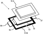
図9に、外装体における接合部位に弱接合部分が形成されてなる安全機構が設けられたラミネート外装蓄電デバイスの一例における構成を分解して示す。このラミネート外装蓄電デバイス50の外装体は、上部外装フィルム51Aと下部外装フィルム51Bとが重ね合わされた状態で、それぞれの外周縁部がその全周にわたって熱シールされて接合部52が形成されることにより、内部に蓄電デバイス要素を収容する収容部が形成されてなるものであり、外装体の収容部内には、薄型の蓄電デバイス要素(例えば、電池要素やキャパシタ要素)55が有機電解液と共に収容されている。
このラミネート外装蓄電デバイス50には、接合部52の一部分に、弱接合部分53が設けられており、この弱接合部分53が安全弁として作用することによって外装体内において多量のガスが発生した場合にも、そのガスを弱接合部分53から放出させて圧力開放を行うことにより、外装体が破裂することが防止される。具体的には、弱接合部分53は、接合部52における他の部分よりシール強度が低くなっており、外装体における蓄電デバイス要素(電池要素やキャパシタ要素)が収容された収容部の内部圧力が所定の値に達すると、弱接合部分53が優先的に剥離して排気口が形成されるものである。
また、この図の例においては、外装体は長方形の輪郭形状を有しており、短辺側の2辺の各々から、蓄電デバイス要素(電池要素やキャパシタ要素)55を構成する複数の正極板の各々に電気的に接続された共通の正極リード部材である正極用電源タブ56、および複数の負極板の各々に電気的に接続された共通の負極リード部材である負極用電源タブ57が引き出されている。
FIG. 9 shows an exploded configuration of an example of a laminated exterior power storage device provided with a safety mechanism in which a weakly joined portion is formed at a joined site in an exterior body. The laminate body of the laminated exterior
The laminated exterior
Moreover, in the example of this figure, the exterior body has a rectangular outline shape, and a plurality of positive electrode plates constituting an electric storage device element (battery element or capacitor element) 55 from each of the two short sides. A positive
このような構成のラミネート外装蓄電デバイスにおいては、安全機構を構成する弱接合部分には、収容用空間の内部圧力が所定の値に達したときに確実に剥離してに排気口が形成され、かつ、通常の使用状態においては、確実に密閉されて十分な信頼性が確保される程度のシール強度が要求される。然るに、製造上の観点から、このようなシール強度を有する弱接合部分を確実に形成することは容易ではない。 In the laminated exterior electricity storage device having such a configuration, the weakly bonded portion constituting the safety mechanism is formed with an exhaust port to be surely peeled when the internal pressure of the accommodating space reaches a predetermined value, Moreover, in a normal use state, a sealing strength that is surely sealed and ensures sufficient reliability is required. However, it is not easy to reliably form a weakly bonded portion having such a sealing strength from the viewpoint of manufacturing.
また、ラミネート外装蓄電デバイスの安全機構としては、接合部が形成された領域の少なくとも一箇所に、非接合部位が蓄電デバイス要素が収容される収容部に連続しかつ収容部に対して入り江状に設けられることにより、圧力集中部が形成され、この非接合部位が形成された領域に、外装フィルムの剥離によって内部と外部とを連通させる圧力開放部が形成されてなるものが提案されている(特許文献6参照)。
しかしながら、このような安全機構においては、内部圧力が急激に上昇した場合には、圧力集中部で剥離が生じにくいため、外装体が破裂する恐れがあり、また、比較的低い圧力で応力集中部において剥離させるためには、圧力集中部における融着幅を相当に小さくすることが必要であるため、通常の使用状態において、十分な気密性を確保することが困難である、という問題がある。
In addition, as a safety mechanism of the laminated exterior power storage device, at least one of the regions where the joint portion is formed, the non-joint portion is continuous with the housing portion in which the power storage device element is housed and is formed in a cove shape with respect to the housing portion. By providing, a pressure concentration part is formed, and in the region where the non-bonded part is formed, a pressure release part that communicates the inside and the outside by peeling of the exterior film is formed ( (See Patent Document 6).
However, in such a safety mechanism, when the internal pressure suddenly increases, the pressure concentration portion is unlikely to peel off, so the exterior body may be ruptured. In order to make it peel in this, since it is necessary to make the fusion width in a pressure concentration part considerably small, there exists a problem that it is difficult to ensure sufficient airtightness in a normal use state.
更に、その他のラミネート外装蓄電デバイスの安全機構としては、外装体を構成する外装フィルムとして、内面側から熱融着性樹脂フィルム、金属箔および剛性を有する樹脂フィルムがこの順で積層されてなるものを用い、当該外装フィルムにおける金属箔に切り込みが設けられた構造のものが提案されている(特許文献7参照。)。
しかしながら、このような安全機構においては、外装体内の気密性が十分に確保されず、電解液の液漏れが生じる恐れがある。
Furthermore, as a safety mechanism of other laminated exterior power storage devices, as an exterior film constituting the exterior body, a heat-fusible resin film, a metal foil, and a rigid resin film are laminated in this order from the inner surface side. And a structure in which a cut is provided in the metal foil of the exterior film (see Patent Document 7).
However, in such a safety mechanism, the airtightness in the exterior body is not sufficiently ensured, and there is a possibility that the electrolyte solution leaks.
本発明は、以上の事情に基づいてなされたものであって、その目的は、通常の使用状態において十分な気密性が得られ、ラミネート外装蓄電デバイスの外装体の内部にガスが発生した場合においては、そのガスを、特定の部位から確実に排出することができるラミネート外装蓄電デバイスの安全機構を提供することにある。 The present invention has been made on the basis of the above circumstances, and its purpose is that when sufficient airtightness is obtained in a normal use state, and gas is generated inside the exterior body of the laminated exterior electricity storage device. An object of the present invention is to provide a safety mechanism for a laminated exterior power storage device that can reliably discharge the gas from a specific part.
本発明のラミネート外装蓄電デバイスの安全機構は、互いに重ね合わせた外装フィルムが、それぞれの外周縁部に形成された接合部において相互に気密に接合されてなる外装体を有し、当該外装体の内部に形成された収容部に蓄電デバイス要素および電解液が収容されて構成されたラミネート外装蓄電デバイスの安全機構であって、
少なくとも一方の外装フィルムの外面に、当該外装フィルムの接合部に固定され、少なくとも一端部が前記接合部以外の部分に位置するよう配置された針状部材が設けられていることを特徴とする。
The safety mechanism of the laminated exterior power storage device of the present invention includes an exterior body in which exterior films stacked on each other are airtightly joined to each other at joint portions formed on the respective outer peripheral edges. A safety mechanism for a laminated exterior power storage device configured by storing an electrical storage device element and an electrolytic solution in a storage portion formed inside,
The outer surface of at least one of the exterior films is provided with a needle-like member that is fixed to a joint portion of the exterior film and arranged so that at least one end portion is located at a portion other than the joint portion.
本発明のラミネート外装蓄電デバイスの安全機構においては、前記針状部材の両端部が前記外装フィルムにおける接合部以外の部分に位置するよう配置されていてもよい。
また、本発明のラミネート外装蓄電デバイスの安全機構においては、前記外装フィルムの各々の外周縁部に、当該外装フィルムの接合部に包囲され、当該外装体の収容部に連通する非接合部位が形成されており、前記針状部材における少なくとも一端部が前記非接合部位に位置するよう配置されていることが好ましい。
このようなラミネート外装蓄電デバイスの安全機構においては、前記接合部は、前記非接合部位に突出する突出部分を有し、当該接合部の突出部分に前記針状部材が固定されていることが好ましい。
また、本発明のラミネート外装蓄電デバイスの安全機構においては、複数の前記針状部材が設けられていてもよい。
また、本発明のラミネート外装蓄電デバイスの安全機構においては、外装体の内部圧力の上昇と共に前記外装フィルムが前記針状部材によって穿孔されることにより、当該外装フィルムにガス排出孔が形成される。
In the safety mechanism of the laminated exterior power storage device of the present invention, both end portions of the needle-like member may be arranged so as to be located at portions other than the joint portion in the exterior film.
Further, in the safety mechanism of the laminated exterior power storage device of the present invention, a non-joined portion that is surrounded by the joint portion of the exterior film and communicates with the housing portion of the exterior body is formed on each outer peripheral edge portion of the exterior film. It is preferable that at least one end portion of the needle-like member is disposed so as to be located at the non-joined portion.
In such a safety mechanism of the laminated exterior power storage device, it is preferable that the joining portion has a projecting portion projecting to the non-joined portion, and the needle-like member is fixed to the projecting portion of the joining portion. .
Moreover, in the safety mechanism of the laminate-cased electricity storage device of the present invention, a plurality of the needle-like members may be provided.
In the safety mechanism of the laminated exterior power storage device of the present invention, the exterior film is pierced by the needle-like member as the internal pressure of the exterior body increases, whereby a gas discharge hole is formed in the exterior film.
本発明のラミネートフィルム外装蓄電デバイスの安全機構においては、外装体内における蓄電デハイス要素が収容される収容部内にガスが発生すると、外装体の内部圧力が上昇することにより、外装体が膨張する。而して、外装体を構成する2枚の外装フィルムのいずれにもガスを排出するための孔が形成されていないため、通常の使用状態において十分な気密性が得られるが、2枚の外装フィルムの少なくとも一方の外装フィルムの外面には、一端部が外装フィルムにおける接合部以外の部分に位置するよう配置された針状部材が、当該外装フィルムの接合部に固定されているため、収容部内にガスが発生して外装体が膨張したときには、針状部材の一端部が外装フィルムを突き刺して穿孔することにより、当該外装フィルムにガス排出孔が形成され、その結果、外装体内のガスが外部に排出される。
従って、本発明のラミネート外装蓄電デバイスの安全機構によれば、外装フィルムには、従来の安全機構において形成されていたガス排出孔が形成されていないため、通常の使用状態において十分な気密性が得られ、しかも、外装体の内部においてガスが発生した場合に、当該ガスの発生による内部圧力の上昇に伴って内部が膨張したときには、針状部材によって比較的低い内部圧力で外装フィルムの特定の部位にガス排出孔が形成されるので、発生したガスをガス排出孔から外部に確実に排出することができる。
In the safety mechanism of the laminated film exterior power storage device of the present invention, when gas is generated in the housing portion in which the electrical storage device is housed in the exterior body, the exterior body expands due to an increase in internal pressure of the exterior body. Thus, since no hole for exhausting gas is formed in any of the two exterior films constituting the exterior body, sufficient airtightness can be obtained in a normal use state. On the outer surface of at least one exterior film of the film, a needle-like member arranged so that one end is located at a portion other than the joint portion in the exterior film is fixed to the joint portion of the exterior film. When the gas is generated and the exterior body expands, one end of the needle-like member pierces and punctures the exterior film, thereby forming a gas discharge hole in the exterior film. To be discharged.
Therefore, according to the safety mechanism of the laminated exterior power storage device of the present invention, the exterior film does not have the gas discharge holes formed in the conventional safety mechanism, and therefore has sufficient airtightness in a normal use state. In addition, when gas is generated inside the exterior body, when the interior expands with an increase in internal pressure due to the generation of the gas, a specific shape of the exterior film can be obtained at a relatively low internal pressure by the needle-like member. Since the gas discharge hole is formed in the part, the generated gas can be reliably discharged to the outside from the gas discharge hole.
以下、本発明の実施の形態について詳細に説明する。
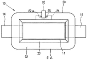
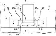
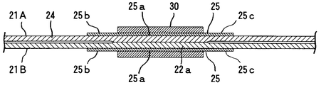
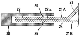
図1は、本発明の安全機構が設けられたラミネート外装蓄電デバイスの一例の構成を示す説明用平面図であり、図2は、図1のラミネート外装蓄電デバイスの安全機構を拡大して示す説明図、図3は、図2のラミネート外装蓄電デバイスの安全機構のA−Aを切断して示す説明用断面図、図4は、図2のラミネート外装蓄電デバイスの安全機構のB−Bを切断して示す説明用断面図である。である。
このラミネート外装蓄電デバイス10においては、外装体20は、それぞれ熱融着性を有する長方形の上部外装フィルム21Aおよび下部外装フィルム21Bが、互いに重ね合わせた状態で、それぞれの外周縁部の全周にわたって形成された接合部22において相互に気密に接合されて構成されている。外装体20の内部には、蓄電デバイス要素が収容される平面形状が矩形の収容部23が形成され、当該収容部23内には、蓄電デバイス要素が有機電解液と共に収容されている。
また、図示の例では、上部外装フィルム21Aにおける収容部23を形成する部分には、絞り加工が施されている。
Hereinafter, embodiments of the present invention will be described in detail.
FIG. 1 is an explanatory plan view showing a configuration of an example of a laminated exterior power storage device provided with the safety mechanism of the present invention, and FIG. 2 is an enlarged view showing a safety mechanism of the laminated exterior power storage device of FIG. FIG. 3 is a cross-sectional view for explaining the safety mechanism AA of the laminated exterior power storage device of FIG. 2, and FIG. 4 is a sectional view of BB of the safety mechanism of the laminate exterior power storage device of FIG. FIG. It is.
In this laminated exterior
In the example shown in the drawing, the portion of the upper
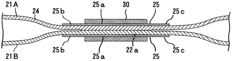
外装体20における上部外装フィルム21Aおよび下部外装フィルム21Bの外周縁部には、その一辺が収容部23に連通し、その他の辺が接合部22に包囲された非接合部位24が形成されており、接合部22は、非接合部位24を包囲する一辺から当該非接合部位24に突出するよう形成された突出部分22aを有する。
上部外装フィルム21Aおよび下部外装フィルム21Bの各々の外面には、針状部材25が設けられている。具体的には、針状部材25の各々は、接合部22における非接合部位24を包囲する一辺に平行に並ぶよう配置され、当該針状部材25の各々の中央部分25aが、上部外装フィルム21Aおよび下部外装フィルム21Bの接合部22の突出部分22aに位置されてクリップ30によって固定され、一端部25bおよび他端部25cの各々が非接合部位24に位置されている。
On the outer peripheral edge of the upper exterior film 21A and the lower exterior film 21B in the
Needle-
外装体20を構成する上部外装フィルム21Aおよび下部外装フィルム21Bとしては、例えば内側からポリプロピレン(以下、「PP」という。)層、アルミニウム層およびナイロン層などがこの順で積層されてなるものを好適に用いることができる。
上部外装フィルム21Aおよび下部外装フィルム21Bとして、例えばPP層、アルミニウム層およびナイロン層が積層されてなるものを用いる場合には、その厚みは、通常、50〜300μmである。
上部外装フィルム21Aおよび下部外装フィルム21Bの縦横の寸法は、収容部23に収容される蓄電デハイス要素11の寸法に応じて適宜選択されるが、例えば縦方向の寸法が40〜200mm、横方向の寸法が60〜300mmである。
また、上部外装フィルム21Aおよび下部外装フィルム21Bの接合部22の接合幅は、例えば2〜15mmである。
As the upper exterior film 21A and the lower exterior film 21B constituting the
When using, for example, a laminate of a PP layer, an aluminum layer and a nylon layer as the upper exterior film 21A and the lower exterior film 21B, the thickness is usually 50 to 300 μm.
The vertical and horizontal dimensions of the upper exterior film 21A and the lower exterior film 21B are appropriately selected according to the dimensions of the
Moreover, the junction width of the
針状部材25を構成する材料としては、ステンレス、銅、チタン等の金属材料、セラミックス材料、硬質樹脂材料などを用いることができる。
針状部材25の全長は、上部外装フィルム21Aの各部の寸法にもよるが、例えば5〜100mm、好ましくは10〜80mmである。
また、針状部材25における接合部22に位置される中央部分25aの長さR1は、例えば1mm以上、好ましくは3mm以上であり、非接合部位24に位置される一端部25bおよび他端部25cの長さR2,R3は、それぞれ例えば1〜30mm、好ましくは2〜10mmである。
また、針状部材25の径は、0.1〜3mm、好ましくは0.2〜2mmである。
また、針状部材25と接合部22の一辺との離間距離Dは、例えば1〜30mm、好ましくは2〜10mmである。
As a material constituting the needle-
The total length of the needle-
Further, the length R1 of the central portion 25a located at the
The diameter of the needle-
Moreover, the separation distance D between the needle-
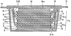
ラミネート外装蓄電デバイス10を構成する蓄電デバイス要素11は、図5に示すように、セパレータSを介して、それぞれ正極集電体12a上に正極層12が形成されてなる複数の正極板と、それぞれ負極集電体13a上に負極層13が形成されてなる複数の負極板とが交互に積層されて構成された電極積層体11aを有し、この電極積層体11aの上面には、リチウムイオンの供給源であるリチウム金属(リチウム極層)18が配置され、このリチウム金属18上には、リチウム極集電体18aが積層されている。また、19は、リチウム極取り出し部材である。
複数の正極板の各々は、取り出し部材16を介して、共通の正極リード部材である、例えばアルミニウム製の正極用電源タブ14に電気的に接続されている。一方、複数の負極板の各々は、取り出し部材17を介して、共通の負極リード部材である、例えば銅製の負極用電源タブ15に電気的に接続されている。
そして、正極用電源タブ14および負極用電源タブ15の各々は、外装体20における一端および他端から外部に突出するよう引き出されている。
As shown in FIG. 5, the power
Each of the plurality of positive electrode plates is electrically connected to a common positive electrode lead member, for example, aluminum positive electrode
Each of the positive electrode
蓄電デバイス要素11を構成する正極層12としては、電極材料を、必要に応じて導電材(例えば、活性炭、カーボンブラック等)およびバインダー等を加えて成形したものが用いられる。正極12を構成する電極材料としては、リチウムを可逆的に担持可能であれば、特に限定されないが、例えば、LiCoO2 、LiNiO2 、LiFeO2 等の一般式:Lix My Oz (但し、Mは金属原子を示し、x、yおよびzは整数である。)で表される金属酸化物等の正極活物質、活性炭などが挙げられる。
また、蓄電デバイス要素11を構成する負極層13としては、電極材料をバインダーで成形したものが用いられる。負極層13の電極材料としては、リチウムを可逆的に担持できるものであれば特に限定されないが、例えばグラファイト、種々の炭素材料、ポリアセン系物質、錫酸化物、珪素酸化合物等の粉末状、粒状の負極活物質などが挙げられる。
As the
Moreover, as the
また、電解液としては、適宜の有機溶媒中に電解質が溶解されてなるものを用いることが好ましい。有機溶媒の具体例としては、例えばエチレンカーボネート、プロピレンカーボネート、ジメチルカーボネート、ジエチルカーボネート、アセトニトリル、ジメトキシエタン等の非プロトン性有機溶媒が挙げられ、これらは単独でまたは2種類以上を組み合わせて用いることができる。また、電解質としては、リチウムイオンを生成しうるものが用いられ、その具体例としては、LiI、LiCIO4 、LiAsF4 、LiBF4 、LiPF6 などが挙げられる。 Further, as the electrolytic solution, it is preferable to use an electrolyte in which an electrolyte is dissolved in an appropriate organic solvent. Specific examples of the organic solvent include aprotic organic solvents such as ethylene carbonate, propylene carbonate, dimethyl carbonate, diethyl carbonate, acetonitrile, and dimethoxyethane. These may be used alone or in combination of two or more. it can. As the electrolyte, which can produce lithium ion is used, and specific examples thereof, LiI, LiCIO 4, LiAsF 4 , LiBF 4, etc. LiPF 6 and the like.
このようなラミネート外装蓄電デバイス10は、例えば以下のようにして製造することができる。
下部外装フィルム21B上における収容部23となる位置に、蓄電デバイス要素11を配置し、この蓄電デバイス要素11上に上部外装フィルム21Aを重ね合わせ、この状態で、上部外装フィルム21Aおよび下部外装フィルム21Bの外周縁部における3辺を熱融着する。これにより、上部外装フィルム21Aおよび下部外装フィルム21Bの外周縁部における3辺に接合部22が形成される。
次いで、上部外装フィルム21Aおよび下部外装フィルム21Bの間に電解液を注入し、更に、上部外装フィルム21Aおよび下部外装フィルム21Bの外周縁部における未融着の1辺を熱融着することにより、外装体20が形成される。
そして、外装体20を構成する上部外装フィルム21Aおよび下部外装フィルム21Bの外面における所要の位置に、針状部材25を配置してクリップ30によって固定することにより、安全機構を具えたラミネート外装蓄電デバイス10が得られる。
Such a laminated exterior
The electricity
Next, by injecting an electrolyte between the upper exterior film 21A and the lower exterior film 21B, and further thermally fusing one side of the outer periphery of the upper exterior film 21A and the lower exterior film 21B, The
Then, the laminated exterior electricity storage device provided with a safety mechanism by disposing the needle-
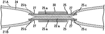
上記のラミネートフィルム外装蓄電デバイス10の安全機構においては、外装体20内における蓄電デハイス要素が収容される収容部23内にガスが発生すると、外装体20の内部圧力が上昇することにより、外装体20が膨張する。ここで、収容部23内に発生したガスは、外周縁部に形成された非接合部位24内に進入するため、外装体20の収容部23のみならず、図6に示すように、上部外装フィルム21Aおよび下部外装フィルム21Bの非接合部位24も膨張する。而して、外装体20を構成する上部外装フィルム21Aおよび下部外装フィルム21Bのいずれにもガスを排出するための孔が形成されていないため、通常の使用状態において十分な気密性が得られるが、上部外装フィルム21Aおよび下部外装フィルム21Bの各々の外面には、一端部25bおよび他端部25cの各々が上部外装フィルム21Aおよび下部外装フィルム21Bにおける非接合部位24に位置するよう配置された針状部材25が、上部外装フィルム21Aおよび下部外装フィルム21Bの接合部22おける突出部分22aに固定されているため、図7に示すように、上部外装フィルム21Aおよび下部外装フィルム21Bの非接合部位24が更に膨張したときには、針状部材25の一端部25bおよび他端部25cのいずれか一方または両方が、上部外装フィルム21Aまたは下部外装フィルム21Bを突き刺して穿孔することにより、上部外装フィルム21Aまたは下部外装フィルム21Bにガス排出孔27が形成され、その結果、外装体20内のガスが外部に排出される。
従って、このようなラミネート外装蓄電デバイス10の安全機構によれば、従来の安全機構において形成されていたガス排出孔が形成されていないため、通常の使用状態において十分な気密性が得られ、しかも、外装体20の内部においてガスが発生した場合に、当該ガスの発生による内部圧力の上昇に伴って内部が膨張したときには、比較的低い内部圧力で下部外装フィルム21Bの特定の部位にガス排出孔27が形成されるので、発生したガスをガス排出孔27から外部に確実に排出することができる。
In the safety mechanism of the laminated film exterior
Therefore, according to the safety mechanism of the laminated exterior
このような構成を有する本発明のラミネートフィルム外装蓄電デバイスの安全機構は、ラミネートフィルム外装蓄電デバイスが、リチウムイオンキャパシタなどの有機電解質キャパシタであるものの他、有機電解質電池であるものにも適用することができるが、有機電解質キャパシタが、有機電解質電池に比べ充電容量が小さいが瞬時に充電、放電できる構成を有するものであることから、ガス圧変化が大きくなる可能性があるため、特に、ラミネートフィルム外装蓄電デバイスが有機電解質キャパシタよりなるものである場合に有効である。 The safety mechanism of the laminated film-clad electricity storage device of the present invention having such a configuration is applicable to the laminated film-clad electricity storage device which is an organic electrolyte battery in addition to an organic electrolyte capacitor such as a lithium ion capacitor. However, the organic electrolyte capacitor has a smaller charge capacity than the organic electrolyte battery but can be charged and discharged instantly. This is effective when the exterior power storage device is made of an organic electrolyte capacitor.
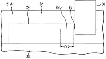
以上、本発明のラミネート外装蓄電デバイスの安全機構について、その実施の形態を説明したが、本発明は上記の実施の形態に限定されるものではなく、種々の変更を加えることができる。
例えば図8に示すように、針状部材25は、その一端部25b(または他端部25c)が非接合部位24に位置され、その他の部分が接合部22に位置されてクリップ30によって固定されていてもよい。このような構成においては、針状部材25における非接合部位24に位置される一端部25b(または他端部25c)の長さR2は、例えば1〜30mm、好ましくは2〜10mmであり、接合部22に固定されるその他の部分の長さは、例えば1mm以上、好ましくは3mm以上である。
また、針状部材25は、上部外装フィルム21Aおよび下部外装フィルム21Bのいずれか一方のみに設けられていてもよい。
また、針状部材25を固定する手段としては、クリップ30に限定されず、適宜の固定手段、例えばテープ等の固定部材などを利用することができる。
As described above, the embodiment of the safety mechanism of the laminated exterior power storage device of the present invention has been described. However, the present invention is not limited to the above embodiment, and various modifications can be made.
For example, as shown in FIG. 8, the needle-
Further, the needle-
In addition, the means for fixing the needle-
10 ラミネート外装蓄電デバイス
11 蓄電デバイス要素
11a 電極積層体
12 正極層
12a 正極集電体
13 負極層
13a 負極集電体
14 正極用電源タブ 15 負極用電源タブ 16,17 取り出し部材
18 リチウム金属(リチウム極層)
18a リチウム極集電体
19 リチウム極取り出し部材
20 外装体
21A 上部外装フィルム
21B 下部外装フィルム
22 接合部
22a 突出部分
23 収容部
24 非接合部位
25 針状部材
25a 中央部分
25b 一端部
25c 他端部
27 ガス排出孔
30 クリップ
50 ラミネート外装蓄電デバイス
51A 上部外装フィルム
51B 下部外装フィルム
52 接合部
53 弱接合部分
55 蓄電デバイス要素
56 正極用電源タブ
57 負極用電源タブ
S セパレータ
DESCRIPTION OF
18a Lithium electrode
Claims (6)
少なくとも一方の外装フィルムの外面に、当該外装フィルムの接合部に固定され、少なくとも一端部が前記接合部以外の部分に位置するよう配置された針状部材が設けられていることを特徴とするラミネート外装蓄電デバイスの安全機構。 The exterior films stacked on each other have exterior bodies that are airtightly joined to each other at the joints formed on the respective outer peripheral edges, and the storage device element and the storage device formed in the interior of the exterior body It is a safety mechanism of a laminated exterior power storage device configured to contain an electrolyte solution,
A laminate characterized in that an outer surface of at least one exterior film is provided with a needle-like member that is fixed to a joint portion of the exterior film and arranged so that at least one end portion is located at a portion other than the joint portion. Safety mechanism for external power storage devices.
Priority Applications (1)
| Application Number | Priority Date | Filing Date | Title |
|---|---|---|---|
| JP2009073285A JP2010225496A (en) | 2009-03-25 | 2009-03-25 | Safety mechanism for laminated exterior power storage devices |
Applications Claiming Priority (1)
| Application Number | Priority Date | Filing Date | Title |
|---|---|---|---|
| JP2009073285A JP2010225496A (en) | 2009-03-25 | 2009-03-25 | Safety mechanism for laminated exterior power storage devices |
Publications (1)
| Publication Number | Publication Date |
|---|---|
| JP2010225496A true JP2010225496A (en) | 2010-10-07 |
Family
ID=43042460
Family Applications (1)
| Application Number | Title | Priority Date | Filing Date |
|---|---|---|---|
| JP2009073285A Withdrawn JP2010225496A (en) | 2009-03-25 | 2009-03-25 | Safety mechanism for laminated exterior power storage devices |
Country Status (1)
| Country | Link |
|---|---|
| JP (1) | JP2010225496A (en) |
Cited By (7)
| Publication number | Priority date | Publication date | Assignee | Title |
|---|---|---|---|---|
| WO2011132723A1 (en) * | 2010-04-24 | 2011-10-27 | Fdk株式会社 | Electrical storage device and electrical storage module having internal pressure releasing mechanism |
| JP2011233604A (en) * | 2010-04-24 | 2011-11-17 | Fdk Corp | Power storage device |
| JP2011249428A (en) * | 2010-05-24 | 2011-12-08 | Fdk Corp | Storage module with explosion-proof function |
| WO2012086855A1 (en) * | 2010-12-20 | 2012-06-28 | 주식회사 엘지화학 | Lithium secondary battery having multi-directional lead-tab structure |
| JP2021510444A (en) * | 2018-12-07 | 2021-04-22 | エルジー・ケム・リミテッド | Pouch-type battery cell including venting member and battery pack containing it |
| CN114879040A (en) * | 2022-05-19 | 2022-08-09 | 广东汽车检测中心有限公司 | Battery package acupuncture testing arrangement |
| JP2023532678A (en) * | 2021-06-02 | 2023-07-31 | エルジー エナジー ソリューション リミテッド | Pouch type battery cell including sealing part venting adjustment means |
-
2009
- 2009-03-25 JP JP2009073285A patent/JP2010225496A/en not_active Withdrawn
Cited By (13)
| Publication number | Priority date | Publication date | Assignee | Title |
|---|---|---|---|---|
| WO2011132723A1 (en) * | 2010-04-24 | 2011-10-27 | Fdk株式会社 | Electrical storage device and electrical storage module having internal pressure releasing mechanism |
| JP2011233604A (en) * | 2010-04-24 | 2011-11-17 | Fdk Corp | Power storage device |
| JP2011249428A (en) * | 2010-05-24 | 2011-12-08 | Fdk Corp | Storage module with explosion-proof function |
| WO2012086855A1 (en) * | 2010-12-20 | 2012-06-28 | 주식회사 엘지화학 | Lithium secondary battery having multi-directional lead-tab structure |
| US8968910B2 (en) | 2010-12-20 | 2015-03-03 | Lg Chem, Ltd. | Lithium secondary battery having multi-directional lead-tab structure |
| JP7062863B2 (en) | 2018-12-07 | 2022-05-09 | エルジー エナジー ソリューション リミテッド | Pouch-type battery cell including venting member and battery pack containing it |
| JP2021510444A (en) * | 2018-12-07 | 2021-04-22 | エルジー・ケム・リミテッド | Pouch-type battery cell including venting member and battery pack containing it |
| US11522249B2 (en) | 2018-12-07 | 2022-12-06 | Lg Energy Solution, Ltd. | Pouch-type battery cell including venting member and battery pack including the same |
| US12597675B2 (en) | 2018-12-07 | 2026-04-07 | Lg Energy Solution, Ltd. | Pouch-type battery cell including venting member and battery pack including the same |
| JP2023532678A (en) * | 2021-06-02 | 2023-07-31 | エルジー エナジー ソリューション リミテッド | Pouch type battery cell including sealing part venting adjustment means |
| JP7531972B2 (en) | 2021-06-02 | 2024-08-13 | エルジー エナジー ソリューション リミテッド | Pouch-type battery cell including sealing portion venting adjustment means |
| US12494545B2 (en) | 2021-06-02 | 2025-12-09 | Lg Energy Solution, Ltd. | Pouch-shaped battery cell including sealed portion venting adjustment means |
| CN114879040A (en) * | 2022-05-19 | 2022-08-09 | 广东汽车检测中心有限公司 | Battery package acupuncture testing arrangement |
Similar Documents
| Publication | Publication Date | Title |
|---|---|---|
| JP5059890B2 (en) | Laminate exterior power storage device | |
| JP6250921B2 (en) | battery | |
| JP2010153841A (en) | Safety mechanism for laminate external package electric storage device | |
| JP2012243556A (en) | Laminated battery, method of detecting expansion of the same, and battery module | |
| JP2009146812A (en) | Battery case and battery pack | |
| JP2011044332A (en) | Laminated outer package power storage device | |
| JP2010186786A (en) | Electrical storage device and electrical storage device module | |
| JP2010086753A (en) | Power storage device | |
| CN114788077B (en) | Electrochemical cell and electrochemical cell module | |
| JP2010033789A (en) | Film-armored electric device assembly | |
| JP2010225496A (en) | Safety mechanism for laminated exterior power storage devices | |
| JP2004006226A (en) | battery | |
| JP2020173989A (en) | Non-aqueous electrolyte secondary battery | |
| JP2016162744A (en) | Storage element and lead terminal | |
| US20130280576A1 (en) | Battery | |
| KR101821488B1 (en) | Battery | |
| JP2010049913A (en) | Manufacturing method of sealed battery | |
| JP5479203B2 (en) | Power storage device | |
| KR20110073837A (en) | Secondary battery | |
| JP5178606B2 (en) | Laminate exterior power storage device | |
| JP2005071673A (en) | battery | |
| JP5224336B2 (en) | Film exterior electrochemical device | |
| JP2010238482A (en) | Laminate exterior power storage device | |
| WO2011125634A1 (en) | Laminated-exterior electricity-storage device and manufacturing method therefor | |
| JP2010238861A (en) | Laminate exterior power storage device |
Legal Events
| Date | Code | Title | Description |
|---|---|---|---|
| A300 | Application deemed to be withdrawn because no request for examination was validly filed |
Free format text: JAPANESE INTERMEDIATE CODE: A300 Effective date: 20120605 |