CN114879040A - Battery package acupuncture testing arrangement - Google Patents
Battery package acupuncture testing arrangement Download PDFInfo
- Publication number
- CN114879040A CN114879040A CN202210545382.0A CN202210545382A CN114879040A CN 114879040 A CN114879040 A CN 114879040A CN 202210545382 A CN202210545382 A CN 202210545382A CN 114879040 A CN114879040 A CN 114879040A
- Authority
- CN
- China
- Prior art keywords
- battery pack
- mounting
- transparent high
- side plate
- testing platform
- Prior art date
- Legal status (The legal status is an assumption and is not a legal conclusion. Google has not performed a legal analysis and makes no representation as to the accuracy of the status listed.)
- Granted
Links
- 238000012360 testing method Methods 0.000 title claims abstract description 133
- 238000001467 acupuncture Methods 0.000 title claims description 34
- 238000009434 installation Methods 0.000 claims abstract description 68
- 238000003825 pressing Methods 0.000 claims abstract description 49
- 230000007246 mechanism Effects 0.000 claims description 49
- 238000005452 bending Methods 0.000 claims description 19
- 238000007789 sealing Methods 0.000 claims description 13
- XLYOFNOQVPJJNP-UHFFFAOYSA-N water Substances O XLYOFNOQVPJJNP-UHFFFAOYSA-N 0.000 claims description 13
- 230000001105 regulatory effect Effects 0.000 claims 4
- 238000004519 manufacturing process Methods 0.000 abstract description 5
- 238000009781 safety test method Methods 0.000 abstract description 2
- 238000009950 felting Methods 0.000 abstract 1
- 238000010586 diagram Methods 0.000 description 6
- 238000000034 method Methods 0.000 description 6
- 238000009792 diffusion process Methods 0.000 description 2
- HBBGRARXTFLTSG-UHFFFAOYSA-N Lithium ion Chemical compound [Li+] HBBGRARXTFLTSG-UHFFFAOYSA-N 0.000 description 1
- 229910000831 Steel Inorganic materials 0.000 description 1
- 230000000712 assembly Effects 0.000 description 1
- 238000000429 assembly Methods 0.000 description 1
- 230000008094 contradictory effect Effects 0.000 description 1
- 239000011521 glass Substances 0.000 description 1
- 229910001416 lithium ion Inorganic materials 0.000 description 1
- 239000000463 material Substances 0.000 description 1
- 230000035515 penetration Effects 0.000 description 1
- 239000000779 smoke Substances 0.000 description 1
- 239000010959 steel Substances 0.000 description 1
- 230000009466 transformation Effects 0.000 description 1
- 238000000844 transformation Methods 0.000 description 1
- 239000002699 waste material Substances 0.000 description 1
Images


Classifications
-
- G—PHYSICS
- G01—MEASURING; TESTING
- G01R—MEASURING ELECTRIC VARIABLES; MEASURING MAGNETIC VARIABLES
- G01R31/00—Arrangements for testing electric properties; Arrangements for locating electric faults; Arrangements for electrical testing characterised by what is being tested not provided for elsewhere
- G01R31/36—Arrangements for testing, measuring or monitoring the electrical condition of accumulators or electric batteries, e.g. capacity or state of charge [SoC]
-
- G—PHYSICS
- G01—MEASURING; TESTING
- G01R—MEASURING ELECTRIC VARIABLES; MEASURING MAGNETIC VARIABLES
- G01R1/00—Details of instruments or arrangements of the types included in groups G01R5/00 - G01R13/00 and G01R31/00
- G01R1/02—General constructional details
- G01R1/04—Housings; Supporting members; Arrangements of terminals
- G01R1/0408—Test fixtures or contact fields; Connectors or connecting adaptors; Test clips; Test sockets
- G01R1/0416—Connectors, terminals
-
- G—PHYSICS
- G01—MEASURING; TESTING
- G01R—MEASURING ELECTRIC VARIABLES; MEASURING MAGNETIC VARIABLES
- G01R31/00—Arrangements for testing electric properties; Arrangements for locating electric faults; Arrangements for electrical testing characterised by what is being tested not provided for elsewhere
- G01R31/36—Arrangements for testing, measuring or monitoring the electrical condition of accumulators or electric batteries, e.g. capacity or state of charge [SoC]
- G01R31/385—Arrangements for measuring battery or accumulator variables
-
- Y—GENERAL TAGGING OF NEW TECHNOLOGICAL DEVELOPMENTS; GENERAL TAGGING OF CROSS-SECTIONAL TECHNOLOGIES SPANNING OVER SEVERAL SECTIONS OF THE IPC; TECHNICAL SUBJECTS COVERED BY FORMER USPC CROSS-REFERENCE ART COLLECTIONS [XRACs] AND DIGESTS
- Y02—TECHNOLOGIES OR APPLICATIONS FOR MITIGATION OR ADAPTATION AGAINST CLIMATE CHANGE
- Y02E—REDUCTION OF GREENHOUSE GAS [GHG] EMISSIONS, RELATED TO ENERGY GENERATION, TRANSMISSION OR DISTRIBUTION
- Y02E60/00—Enabling technologies; Technologies with a potential or indirect contribution to GHG emissions mitigation
- Y02E60/10—Energy storage using batteries
Landscapes
- Physics & Mathematics (AREA)
- General Physics & Mathematics (AREA)
- Battery Mounting, Suspending (AREA)
- Secondary Cells (AREA)
Abstract
Description
技术领域technical field
本发明涉及电池安全测试领域,尤其涉及一种电池包针刺测试装置。The invention relates to the field of battery safety testing, in particular to a battery pack acupuncture testing device.
背景技术Background technique
锂离子电池的安全状况与许多因素相关,如材料体系、设计水平、生产控制和电池使用情况等。内部短路对电池的危害较大,一般通过针刺热扩散试验来模拟电池发生内部短路时的安全状况。针刺热扩散试验是将一枚钢针以一定的速度刺穿电池。针对不同使用需要或不同类型的电池其穿刺位置往往是不同的,例如有的电池穿刺位置在电池的左侧,有的电池穿刺位置在电池的前侧或顶部等位置,但是现有的针刺设备的刺针往往是固定安装在测试平台的某一位置,穿刺位置不同的电池需要匹配不同的针刺设备,大大增加生产成本。The safety status of lithium-ion batteries is related to many factors, such as material system, design level, production control, and battery usage. The internal short circuit is more harmful to the battery. Generally, the acupuncture thermal diffusion test is used to simulate the safety condition of the battery when the internal short circuit occurs. Needle penetration thermal diffusion test is to pierce a steel needle through the battery at a certain speed. For different use needs or different types of batteries, the puncture position is often different. For example, some battery puncture positions are on the left side of the battery, and some battery puncture positions are on the front side or top of the battery. However, the existing acupuncture position The puncturing needle of the equipment is often fixed at a certain position on the test platform, and batteries with different puncturing positions need to be matched with different acupuncture equipment, which greatly increases the production cost.
发明内容SUMMARY OF THE INVENTION
本发明的目的在于提供一种电池包针刺测试装置,其旨在解决现有的针刺设备的刺针固定安装在测试平台的某一位置,穿刺位置不同的电池需要匹配不同的针刺设备的技术问题。The purpose of the present invention is to provide a battery pack acupuncture test device, which aims to solve the problem that the puncture needle of the existing acupuncture equipment is fixedly installed in a certain position of the test platform, and the batteries with different puncture positions need to be matched with different acupuncture equipment. technical problem.
为达到上述目的,本发明提供的方案是:For achieving the above object, the scheme provided by the invention is:
一种电池包针刺测试装置,用于对电池包进行针刺测试,所述电池包针刺测试装置包括测试平台、刺针模组和压紧组件,所述测试平台用于放置电池包,所述测试平台的左侧和/或右侧设置有第一安装区域,所述测试平台的前侧和/或后侧设置有第二安装区域,所述测试平台的上方设置有第三安装区域,所述测试平台的底部设置有第四安装区域,所述刺针模组安装在第一安装区域、第二安装区域、第三安装区域和第四安装区域的任意一者上,所述刺针模组与所述测试平台可拆卸连接,所述刺针模组用于刺穿电池包,所述压紧组件安装在测试平台上,并用于压紧电池包。A battery pack acupuncture test device for performing acupuncture test on the battery pack, the battery pack acupuncture test device includes a test platform, a puncture needle module and a pressing assembly, the test platform is used for placing the battery pack, and the The left and/or right side of the test platform is provided with a first installation area, the front side and/or the rear side of the test platform is provided with a second installation area, and the top of the test platform is provided with a third installation area, The bottom of the test platform is provided with a fourth installation area, the puncture needle module is installed on any one of the first installation area, the second installation area, the third installation area and the fourth installation area, the puncture needle module Removably connected to the test platform, the puncture needle module is used for piercing the battery pack, and the pressing component is installed on the test platform and used for pressing the battery pack.
优选地,所述测试平台包括底板、前侧板、后侧板、左侧板、右侧板和支脚,所述底板、所述前侧板、所述后侧板、所述左侧板、所述右侧板围合形成工作腔室,所述支脚设置在所述底板底部,所述左侧板和/或所述右侧板设置有所述第一安装区域,所述前侧板和/或所述后侧板设置有所述第二安装区域,所述底板上方设置有所述第三安装区域,所述底板底部设置有所述第四安装区域。Preferably, the test platform comprises a bottom plate, a front side plate, a rear side plate, a left side plate, a right side plate and a supporting foot, the bottom plate, the front side plate, the rear side plate, the left side plate, The right side plate encloses a working chamber, the support feet are arranged at the bottom of the bottom plate, the left side plate and/or the right side plate are arranged with the first installation area, the front side plate and the /or the rear side panel is provided with the second installation area, the third installation area is provided above the bottom plate, and the fourth installation area is provided at the bottom of the bottom plate.
优选地,电池包针刺测试装置还包括消防管,所述消防管设置在测试平台上,所述消防管的出口端面向所述工作腔室,所述消防管的进口端用于与输水管道连接。Preferably, the battery pack acupuncture test device further includes a fire-fighting pipe, the fire-fighting pipe is arranged on the test platform, the outlet end of the fire-fighting pipe faces the working chamber, and the inlet end of the fire-fighting pipe is used to communicate with the water delivery Pipe connection.
优选地,所述压紧组件包括第一压紧机构和第二压紧机构,所述第一压紧机构包括能够沿所述测试平台的前后方向和左右方向滑动的电池支撑背板,所述第二压紧机构包括能够沿所述测试平台的上下方向滑动的挡板。Preferably, the pressing assembly includes a first pressing mechanism and a second pressing mechanism, the first pressing mechanism includes a battery support back plate that can slide in the front-rear direction and the left-right direction of the test platform, the The second pressing mechanism includes a baffle plate that can slide in the up-down direction of the test platform.
优选地,所述挡板设置有所述第三安装区域。Preferably, the baffle is provided with the third installation area.
优选地,所述测试平台在所述第一安装区域处、所述第二安装区域处和所述第四安装区域处均开设有观察窗,所述测试平台还包括多个透明耐高温面板,每个所述透明耐高温面板上均设置有穿刺孔,所述透明耐高温面板的数量与安装区域的数量匹配,一个所述透明耐高温面板覆盖住一个所述观察窗,所述透明耐高温面板能够相对所述测试平台前后滑动和上下滑动,所述刺针模组包括刺针组件和刺针驱动组件,所述刺针组件包括导向机构和耐热密封圈,所述导向机构与所述透明耐高温面板可拆卸连接,并覆盖住所述穿刺孔,所述耐热密封圈设置在所述导向机构与所述透明耐高温面板之间,所述刺针滑动设置在导向机构内,所述刺针驱动组件与所述测试平台可拆卸连接,所述刺针驱动组件用于驱动所述刺针沿所述导向机构滑动并穿过所述穿刺孔刺穿电池包。Preferably, the test platform is provided with observation windows at the first installation area, the second installation area and the fourth installation area, and the test platform further includes a plurality of transparent high temperature resistant panels, Each of the transparent high temperature resistant panels is provided with puncture holes, the number of the transparent high temperature resistant panels matches the number of installation areas, one of the transparent high temperature resistant panels covers one of the observation windows, and the transparent high temperature resistant panels The panel can slide back and forth and up and down relative to the test platform. The lancet module includes a lancet assembly and a lancet drive assembly. The lancet assembly includes a guide mechanism and a heat-resistant sealing ring. The guide mechanism is connected with the transparent high temperature resistant panel. It is detachably connected and covers the puncture hole, the heat-resistant sealing ring is arranged between the guide mechanism and the transparent high-temperature-resistant panel, the puncture needle is slidably arranged in the guide mechanism, and the puncture needle drive assembly is connected to the The test platform is detachably connected, and the lancet drive assembly is used to drive the lancet to slide along the guide mechanism and pierce the battery pack through the puncture hole.
优选地,所述测试平台还包括多个限位板和多组调节件,所述限位板的数量和所述调节件的组数均与所述透明耐高温面板的数量匹配,所述测试平台在所述第一安装区域处、所述第二安装区域处和所述第四安装区域处均凹陷形成有与所述限位板适配的安装槽,所述安装槽与所述观察窗相通,每个所述限位板上均设置有第一滑动槽、通槽和安装孔,所述第一滑动槽竖向贯穿所述限位板,所述通槽横向贯穿所述限位板,所述通槽与所述观察窗对应设置,所述安装孔设置有至少两个,两个或两个以上所述安装孔均设置在所述限位板背离所述观察窗的一侧,并分别与所述第一滑动槽连通,所述透明耐高温面板滑动设置在所述第一滑动槽内,一组所述调节件与一个所述透明耐高温面板匹配,每组所述调节件均包括至少两个所述调节件,一个所述调节件穿过一个所述安装孔与所述透明耐高温面板抵接。Preferably, the test platform further includes a plurality of limit plates and groups of adjustment members, and the number of the limit plates and the number of groups of the adjustment members match the number of the transparent high temperature resistant panels. At the first installation area, the second installation area and the fourth installation area, the platform is recessed to form installation grooves adapted to the limit plate, and the installation grooves are connected to the observation window. Each of the limiting plates is provided with a first sliding slot, a through slot and a mounting hole, the first sliding slot vertically penetrates the limiting plate, and the through slot transversely penetrates the limiting plate , the through slot is arranged corresponding to the observation window, the installation holes are provided with at least two, and two or more of the installation holes are arranged on the side of the limiting plate away from the observation window, and communicate with the first sliding grooves respectively, the transparent high temperature resistant panels are slidably arranged in the first sliding grooves, a group of the adjustment members is matched with one of the transparent high temperature resistant panels, and each group of the adjustment members Each includes at least two adjustment pieces, one of the adjustment pieces is abutted with the transparent high temperature resistant panel through one of the mounting holes.
优选地,所述导向机构包括导管、第一弹性件、推杆、第一塞头和第二塞头,所述导管的第二端设置有环形凸起,所述第一塞头安装在所述导管的第一端,所述第二塞头安装在所述导管的第二端,所述第二塞头背离所述导管的一端安装在所述穿刺孔内,所述推杆设置在所述导管内,并穿过所述第一塞头伸出所述导管外,所述刺针设置在导管内,并穿过所述第二塞头伸出所述导管外,所述第一弹性件套设在所述刺针上,且所述第一弹性件弹性压缩在所述推杆与所述第二塞头之间,所述耐热密封圈设置在所述透明耐高温面板与所述环形凸起之间。Preferably, the guiding mechanism includes a conduit, a first elastic member, a push rod, a first plug and a second plug, the second end of the conduit is provided with an annular protrusion, and the first plug is installed on the The first end of the catheter, the second plug head is installed on the second end of the catheter, the end of the second plug head facing away from the catheter is installed in the puncture hole, and the push rod is arranged in the puncture hole. The puncture needle is arranged in the catheter and protrudes out of the catheter through the second plug, and the first elastic member is sleeved on the puncture needle, and the first elastic member is elastically compressed between the push rod and the second plug, and the heat-resistant sealing ring is arranged on the transparent high-temperature resistant panel and the annular between the bulges.
优选地,所述限位板设置有第二滑动槽,所述刺针组件还包括第二安装支架和第二弹性件,所述第二安装支架呈几字形设置,第二安装支架包括本体、第一弯折部和第二弯折部,所述本体设置有导向槽,所述第一弯折部和所述第二弯折部分别设置在所述本体的底部两侧,所述第一弯折部和所述第二弯折部分别设于所述第二滑动槽内,所述导管安装在所述导向槽内,所述第二弹性件弹性压缩在所述本体与所述环形凸起之间,所述第二安装支架能够沿所述第二滑动槽上下滑动,所述导管能够沿所述导向槽前后滑动。Preferably, the limiting plate is provided with a second sliding groove, the lancet assembly further includes a second mounting bracket and a second elastic member, the second mounting bracket is arranged in a zigzag shape, and the second mounting bracket includes a main body, a second mounting bracket and a second elastic member. A bending part and a second bending part, the main body is provided with a guide groove, the first bending part and the second bending part are respectively arranged on both sides of the bottom of the main body, the first bending part is The folded part and the second folded part are respectively arranged in the second sliding groove, the guide tube is installed in the guide groove, and the second elastic member is elastically compressed on the body and the annular protrusion In between, the second mounting bracket can slide up and down along the second sliding groove, and the conduit can slide back and forth along the guide groove.
优选地,所述刺针驱动组件包括第一安装支架、驱动件、推块、底座和紧固件,所述底座安装在所述测试平台上,并位于所述观察窗的外侧,所述底座沿上下方向设置有多个第二调节孔,所述第一安装支架通过所述紧固件与所述底座连接,所述驱动件安装在所述第一安装支架上,所述推块设置在所述驱动件的输出端,所述导向机构的前后滑动范围落入所述推块的纵向宽度范围内。。Preferably, the lancet driving assembly includes a first mounting bracket, a driving member, a push block, a base and a fastener, the base is mounted on the test platform and is located outside the observation window, and the base is along the A plurality of second adjustment holes are arranged in the up and down direction, the first installation bracket is connected with the base through the fastener, the driving member is installed on the first installation bracket, and the push block is arranged on the base. At the output end of the driving member, the front and rear sliding range of the guide mechanism falls within the longitudinal width range of the push block. .
本发明提供的电池包针刺测试装置通过在测试平台的不同位置均设置有安装区域,并将刺针模组与测试平台的连接方式设置为可拆卸连接的方式,从而使得用户可以根据不同类型电池包的穿刺位置将刺针模组安装在相应的安装区域,从而能够提高电池包针刺测试装置的利用率,降低生产成本,提高经济效益。The battery pack acupuncture test device provided by the present invention is provided with installation areas at different positions of the test platform, and the connection mode of the puncture needle module and the test platform is set in a detachable connection mode, so that the user can choose according to different types of batteries. The puncturing needle module is installed in the corresponding installation area at the puncturing position of the pack, so that the utilization rate of the battery pack acupuncture test device can be improved, the production cost can be reduced, and the economic benefit can be improved.
附图说明Description of drawings
为了更清楚地说明本发明实施例或现有技术中的技术方案,下面将对实施例或现有技术描述中所需要使用的附图作简单地介绍,显而易见地,下面描述中的附图仅仅是本发明的一些实施例,对于本领域普通技术人员来讲,在不付出创造性劳动的前提下,还可以根据这些附图示出的结构获得其他的附图。In order to explain the embodiments of the present invention or the technical solutions in the prior art more clearly, the following briefly introduces the accompanying drawings that need to be used in the description of the embodiments or the prior art. Obviously, the accompanying drawings in the following description are only These are some embodiments of the present invention, and for those of ordinary skill in the art, other drawings can also be obtained according to the structures shown in these drawings without creative efforts.
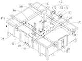
图1是本发明实施例提供的电池包针刺测试装置的使用状态图,此时,刺针模组设置在左侧板上;Fig. 1 is the use state diagram of the battery pack acupuncture test device provided by the embodiment of the present invention, at this time, the needle module is arranged on the left side panel;
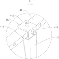
图2是图1中A的放大图;Fig. 2 is the enlarged view of A in Fig. 1;
图3是本发明实施例提供的电池包针刺测试装置另一方向的使用状态图,此时,刺针模组设置在左侧板上;3 is a state diagram of use in another direction of the battery pack acupuncture test device provided by the embodiment of the present invention, at this time, the puncture module is arranged on the left panel;
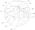
图4是图3中B的放大图;Fig. 4 is the enlarged view of B in Fig. 3;
图5是图3中沿C-C线的剖面图;Fig. 5 is the sectional view along C-C line in Fig. 3;
图6是是图5中D的放大图;Fig. 6 is the enlarged view of D in Fig. 5;
图7是本发明实施例提供的横杆、第二滑块组件和微调机构的组合示意图;7 is a schematic diagram of a combination of a cross bar, a second slider assembly and a fine-tuning mechanism provided by an embodiment of the present invention;
图8是本发明实施例提供的第二安装支架的结构示意图;8 is a schematic structural diagram of a second mounting bracket provided by an embodiment of the present invention;
图9是本发明实施例提供的电池包针刺测试装置的另一使用状态图,此时,刺针模组设置在挡板上;Fig. 9 is another use state diagram of the battery pack acupuncture test device provided by the embodiment of the present invention, at this time, the puncture needle module is arranged on the baffle;
图10是本发明实施例提供的电池包针刺测试装置的再一使用状态图,此时,刺针模组设置在底板上。FIG. 10 is another use state diagram of the battery pack acupuncture test device provided by the embodiment of the present invention. At this time, the puncture needle module is arranged on the bottom plate.
附图标号说明:Description of reference numbers:
10、测试平台;11、工作腔室;12、底板;121、第四安装区域;13、前侧板;131、第二安装区域;14、后侧板;15、左侧板;151、第一凸起;152、第一安装区域;16、右侧板;17、支脚;18、透明耐高温面板;181、穿刺孔;19、观察窗;101、限位板;102、第一滑动槽;103、通槽;104、安装孔;105、第二滑动槽;106、调节件;107、压板;10, test platform; 11, working chamber; 12, bottom plate; 121, fourth installation area; 13, front side panel; 131, second installation area; 14, rear side panel; 15, left side panel; 151, first a protrusion; 152, the first installation area; 16, the right side plate; 17, the feet; 18, the transparent high temperature resistant panel; 181, the puncture hole; 19, the observation window; 101, the limit plate; 102, the first sliding groove ; 103, through groove; 104, installation hole; 105, second sliding groove; 106, adjustment piece; 107, pressure plate;
20、刺针组件;21、刺针;22、导向机构;221、导管;2211、环形凸起;222、第一弹性件;223、推杆;224、第一塞头;225、第二塞头;23、耐热密封圈;24、第二安装支架;241、本体;2411、导向槽;242、第一弯折部;243、第二弯折部;25、第二弹性件;26、垫片;20, lancet assembly; 21, lancet; 22, guide mechanism; 221, catheter; 2211, annular protrusion; 222, first elastic member; 223, push rod; 224, first plug; 225, second plug; 23, heat-resistant sealing ring; 24, second mounting bracket; 241, body; 2411, guide groove; 242, first bending part; 243, second bending part; 25, second elastic part; 26, gasket ;
30、刺针驱动组件;31、第一安装支架;32、驱动件;33、推块;34、底座;35、紧固件;36、第二调节孔;30, lancet drive assembly; 31, first mounting bracket; 32, driving part; 33, push block; 34, base; 35, fastener; 36, second adjustment hole;
40、压紧组件;41、横杆;411、第一调节孔;42、支撑背板;43、第一滑块组件;431、第一滑块;432、第二滑块;433、压紧顶板;434、调节螺栓;435、连接件;44、第二滑块组件;441、第三滑块;442、固定螺栓;443、螺母;45、微调机构;451、第二导轨座;452、第二丝杆;453、第二丝杆安装块;46、挡板;461、第三安装区域;47、升降组件;471、第一导轨座;472、第一丝杆;473、第一丝杆安装块;40, pressing assembly; 41, cross bar; 411, first adjusting hole; 42, supporting back plate; 43, first sliding block assembly; 431, first sliding block; 432, second sliding block; 433, pressing Top plate; 434, adjusting bolt; 435, connecting piece; 44, second slider assembly; 441, third slider; 442, fixing bolt; 443, nut; 45, fine adjustment mechanism; 451, second rail seat; 452, Second screw; 453, Second screw mounting block; 46, Baffle plate; 461, Third installation area; 47, Lifting assembly; 471, First rail seat; 472, First screw; 473, First screw rod mounting block;
50、消防管;50. Fire pipe;
60、排水管;60. Drain pipe;
70、开关阀;70. On-off valve;
80、纵杆。80. Vertical bar.
具体实施方式Detailed ways
下面将结合本发明实施例中的附图,对本发明实施例中的技术方案进行清楚、完整地描述,显然,所描述的实施例仅仅是本发明的一部分实施例,而不是全部的实施例。基于本发明中的实施例,本领域普通技术人员在没有作出创造性劳动前提下所获得的所有其他实施例,都属于本发明保护的范围。The technical solutions in the embodiments of the present invention will be clearly and completely described below with reference to the accompanying drawings in the embodiments of the present invention. Obviously, the described embodiments are only a part of the embodiments of the present invention, not all of the embodiments. Based on the embodiments of the present invention, all other embodiments obtained by those of ordinary skill in the art without creative efforts shall fall within the protection scope of the present invention.
需要说明的是,本发明实施例中所有方向性指示(诸如上、下、左、右、前、后……)仅用于解释在某一特定姿态(如附图所示)下各部件之间的相对位置关系、运动情况等,如果该特定姿态发生改变时,则该方向性指示也相应地随之改变。It should be noted that all directional indications (such as up, down, left, right, front, back...) in the embodiments of the present invention are only used to explain the relationship between various components under a certain posture (as shown in the accompanying drawings). If the specific posture changes, the directional indication also changes accordingly.
还需要说明的是,当元件被称为“固定于”或“设置于”另一个元件上时,它可以直接在另一个元件上或者可能同时存在居中元件。当一个元件被称为是“连接”另一个元件,它可以是直接连接另一个元件或者可能同时存在居中元件。It will also be noted that when an element is referred to as being "fixed to" or "disposed on" another element, it can be directly on the other element or intervening elements may also be present. When an element is referred to as being "connected" to another element, it can be directly connected to the other element or intervening elements may also be present.
另外,在本发明中涉及“第一”、“第二”等的描述仅用于描述目的,而不能理解为指示或暗示其相对重要性或者隐含指明所指示的技术特征的数量。由此,限定有“第一”、“第二”的特征可以明示或者隐含地包括至少一个该特征。另外,各个实施例之间的技术方案可以相互结合,但是必须是以本领域普通技术人员能够实现为基础,当技术方案的结合出现相互矛盾或无法实现时应当认为这种技术方案的结合不存在,也不在本发明要求的保护范围之内。In addition, the descriptions involving "first", "second", etc. in the present invention are only for descriptive purposes, and should not be understood as indicating or implying their relative importance or implying the number of indicated technical features. Thus, a feature delimited with "first", "second" may expressly or implicitly include at least one of that feature. In addition, the technical solutions between the various embodiments can be combined with each other, but must be based on the realization by those of ordinary skill in the art. When the combination of technical solutions is contradictory or cannot be realized, it should be considered that the combination of such technical solutions does not exist. , is not within the scope of protection required by the present invention.
如图1至图10所示,其为本发明的一种实施例的电池包针刺测试装置,其用于对电池包进行针刺测试。以X方向为左右方向的左方,以Y方向为前后方向的前方,以Z方向为上下方向的上方。As shown in FIG. 1 to FIG. 10 , it is a battery pack acupuncture test device according to an embodiment of the present invention, which is used to perform acupuncture test on the battery pack. The X direction is the left in the left and right directions, the Y direction is the front in the front and rear directions, and the Z direction is the upper part in the vertical direction.
请参阅图1-图10所示,本发明实施例的电池包针刺测试装置,包括测试平台10、刺针模组和压紧组件40,测试平台10用于放置电池包,测试平台10的左侧和/或右侧设置有第一安装区域152,测试平台10的前侧和/或后侧设置有第二安装区域131,测试平台10的上方设置有第三安装区域461,测试平台10的底部设置有第四安装区域121,刺针模组安装在第一安装区域152、第二安装区域131、第三安装区域461和第四安装区域121的任意一者上,并与测试平台10可拆卸连接,刺针模组用于完成电池包的针刺测试,压紧组件40安装在测试平台10上,并用于压紧电池包以避免电池包在测试过程中发生移动。Please refer to FIG. 1-FIG. 10. The battery pack acupuncture test device according to the embodiment of the present invention includes a
需要说明的是,当刺针组件20设置在测试平台10的左侧或右侧时,压紧组件40能够从左边或右边压紧电池包,当刺针组件20设置在测试平台10的前侧或后侧时,压紧组件40能够从前边或后边压紧电池包,当刺针组件20设置在测试平台10的上方或底部时,压紧组件40能够从顶部压紧电池包。It should be noted that when the
本发明实施例的电池包针刺测试装置通过在测试平台10的不同位置均设置有安装区域,并将刺针模组与测试平台10的连接方式设置为可拆卸连接的方式,从而使得用户可以根据不同类型电池包的穿刺位置将刺针模组安装在相应的安装区域,从而能够提高电池包针刺测试装置的利用率,降低生产成本,提高经济效益。The battery pack acupuncture test device according to the embodiment of the present invention is provided with installation areas at different positions of the
请参阅图1-图10所示,示例性地,在某些实施例中,测试平台10包括底板12、前侧板13、后侧板14、左侧板15、右侧板16和支脚17,底板12、前侧板13、后侧板14、左侧板15、右侧板16围合形成工作腔室11,支脚17设置在底板12的底部,电池包放置在工作腔室11内,左侧板15和/或右侧板16设置有第一安装区域152,前侧板13和/或后侧板14设置有第二安装区域131,底板12上方设置有第三安装区域461,底板12的底部设置有第四安装区域121。Referring to FIGS. 1-10 , by way of example, in some embodiments, the
需要说明的是,图1、图3和图9中的支脚17的结构与图10中的支脚17的结构是一样。It should be noted that the structure of the
进一步地,电池包针刺测试装置还包括消防管50,消防管50设置在测试平台10上,消防管50的出口端面向工作腔室11,消防管50的进口端与输水管道连接,在对电池包进行测试时,先将消防管50的进口端与输水管道连接(此时,与输水管道连接的供水装置是关闭的),再进行对电池包进行测试,如果在测试过程中,电池包发生热失控,则立马打开供水装置,将水灌入工作腔室11,通过灌水的方式浸泡已经热失控的电池包,能够缩短灭火时间,达到快速灭火和减少烟雾污染的目的,同时能够减少消防水的浪费,此外,采用该灭火方式不需要测试人员靠近电池包进行灭火,测试人员的安全问题得到了保障。Further, the battery pack acupuncture test device further includes a
更进一步地,电池包针刺测试装置还包括排水管60,排水管60设置在测试平台10上,并与工作腔室11连通,排水管60上设置有开关阀70,完成灭火目的后可通过排水管60将工作腔室11内的水排出。Further, the battery pack acupuncture test device also includes a
可选地,排水管60设置在工作腔室11的底部,也可以设置在工作腔室11的下部。Optionally, the
可以理解地,测试平台10可以设置成具有工作腔室11的结构形状,也可以设置成为工作腔室11的结构形状,即测试平台10可以仅包括固定底座34、电池包放置板和支撑结构,电池放置板通过支撑结构安装在固定底座34上,压紧组件40也设置在固定底座34上,固定底座34对应位置设置有各安装区域,刺针模组对应各安装区域可拆卸安装在固定底座34上。It can be understood that the
请参阅图1-图10所示,压紧组件40包括第一压紧机构和第二压紧机构,第一压紧机构包括能够沿测试平台10的前后方向和左右方向滑动的电池支撑背板42,第二压紧机构包括能够沿测试平台10的上下方向滑动的挡板46。Please refer to FIG. 1-FIG. 10 , the pressing
第一压紧机构包括横杆41、支撑背板42、第一滑块组件43和第二滑块组件44,横杆41的两端分别设置有上述第一滑块组件43,其中一个第一滑块组件43与左侧板15滑动连接,另一个第一滑块组件43与右侧板16滑动连接,支撑背板42设于工作腔室11内,支撑背板42通过第二滑块组件44与横杆41滑动连接,在进行测试时,先从前后方向调整支撑背板42,使支撑背板42落入电池包的纵向范围内,再从左右方向滑动调整支撑背板42与电池包的横向距离,直至支撑背板42贴合电池包,从而固定住电池包,避免在测试时,电池包发生横向移动,第一压紧机构结构简单,便于操作。The first pressing mechanism includes a
可以理解地,为了更好地固定住电池包,第一压紧机构可以设置两组,两组第一压紧机构沿测试平台10的前后方向间隔设置。It can be understood that, in order to better fix the battery pack, two groups of first pressing mechanisms may be provided, and the two groups of first pressing mechanisms are arranged at intervals along the front-rear direction of the
可选地,左侧板15顶部和右侧板16顶部均设置有第一凸起151,下面以第一滑块组件43与左侧板15连接为例进行说明,第二滑块组件44与右侧板16的连接关系一样,在此不赘述。Optionally, both the top of the
可选地,第一滑块组件43包括第一滑块431、第二滑块432、压紧顶板433、调节螺栓434和连接件435,第一滑块431呈L型状设置,第二滑块432呈倒L型状设置,第一滑块431底部设置螺纹孔,调节螺栓434穿过螺纹孔与压紧顶板433连接,第一滑块431套设在横杆41上,并位于左侧板15的外侧,压紧顶板433与第一凸起151抵接,第二滑块432套设在横杆41上,并位于左侧板15的内侧,第一滑块431和第二滑块432通过连接件435连接,在调节时,先旋松调节螺栓434使压紧顶板433离开第一凸起151,移动横杆41的纵向位置,移动到位后,将调节螺栓434旋紧使压紧顶板433顶住第一凸起151,避免第一滑块组件43移动,第一滑块组件43结构简单,便于调节。Optionally, the
可选地,第二滑块组件44包括第三滑块441、固定螺栓442和螺母443,横杆41纵向贯穿设置有第一调节孔411,第三滑块441纵向贯设置有连接孔,第三滑块441套设在横杆41上,固定螺栓442穿过连接孔和第一调节孔411后与螺母443连接,在调节时,先松开螺母443,取出固定螺栓442,将第三滑块441移动到位后,装上固定螺栓442和螺母443,避免第二滑块组件44移动,第二滑块组件44结构简单,便于调节。Optionally, the
可以理解地,第一滑块组件43也可以采用其他滑动结构,只要能够带动横杆41可以相对测试平台10前后滑动,并在滑动到位后固定在测试平台10上即可。同理,第二滑块组件44可以也可以采用其他滑动结构,只要能够使支撑背板42可以相对横杆41左右滑动,并在滑动到位后固定在横杆41上即可。It can be understood that the
当刺针模组位于测试平台10的顶部或底部时,可将第二滑块组件44和支撑背板42取下,减少横杆41的负重。When the lancet module is located at the top or bottom of the
第二压紧机构包括挡板46和升降组件47,升降组件47包括第一导轨座471、第一丝杆472和第一丝杆安装块473,第一导轨座471安装在横杆41上,第一丝杆472一端与挡板46转动连接,另一端穿过第一导轨座471与第一丝杆安装块473连接,第一导轨座471与第一丝杆472螺纹连接,转动第一丝杆472能够使第一导轨座471带动挡板46沿测试平台10上下升降,从而实现调整挡板46与电池包之间的距离的目的,当需要压紧电池包时,将挡板46下降至与电池包抵接即可。The second pressing mechanism includes a
可选地,第一导轨座471与横杆41可拆卸连接,当刺针模组位于测试平台10的左侧、右侧、前侧或后侧时,可将第二压紧机构取下,减少横杆41的负重。Optionally, the first
进一步地,第三安装区域461设置在挡板46上,这样设计,当刺针模组位于测试平台10的顶部时,可直接将刺针模组安装在挡板46上,无需设置其他支撑结构来支撑刺针模组。Further, the
更进一步地,当刺针模组安装在第三安装区域461时,电池包针刺测试装置还包括纵杆80,纵杆80的两端分别设置有上述第一滑块组件43,其中一个第一滑块组件43与前侧板13滑动连接,另一个第一滑块组件43与后侧板14滑动连接,通过设置纵杆80能够提高横杆41的承载力,尤其是当挡板46设置在测试平台10的中间位置时,能够避免刺针模组的压力全部施加在横杆41的中段。Further, when the puncture needle module is installed in the
请参阅图1-图10所示,示例性地,在某些实施例中,压紧组件40还包括微调机构45,微调机构45包括第二导轨座451、第二丝杆452和第二丝杆安装块453,第二导轨座451安装在横杆41上,第二丝杆452一端安装在第二丝杆安装块453上,另一端穿过第二导轨座451与第一滑块431转动连接,第二导轨座451与第二丝杆452螺纹连接,能够使第二导轨座451带动安装在横杆41上的支撑背板42沿测试平台10左右滑动,从而实现微调电池包与刺针21之间的距离的目的。Referring to FIGS. 1-10 , for example, in some embodiments, the pressing
可以理解地,刺针组件20和刺针驱动组件30均设置在工作腔室11内,也可以设置在工作腔室11外侧,如果刺针组件20和刺针驱动组件30均设置在工作腔室11外侧,则刺针组件20与测试平台10需要密封连接。下面以刺针组件20和刺针驱动组件30均设置在工作腔室11外侧为例进行说明。It can be understood that the
请参阅图1-图8所示,示例性地,在某些实施例中,测试平台10在第一安装区域152处、第二安装区域131处和第四安装区域121处均开设有观察窗19,测试平台10还包括多个透明耐高温面板18,每个透明耐高温面板18上均设置有穿刺孔181,透明耐高温面板18的数量与安装区域的数量匹配,一个透明耐高温面板18覆盖住一个观察窗19,透明耐高温面板18能够相对测试平台10前后滑动和上下滑动,刺针模组包括刺针组件20和刺针驱动组件30,刺针组件20包括刺针21、导向机构22和耐热密封圈23,导向机构22与透明耐高温面板18可拆卸连接,并覆盖住穿刺孔181,耐热密封圈23设置在导向机构22与透明耐高温面板18之间,刺针21滑动设置在导向机构22内,刺针驱动组件30与测试平台10可拆卸连接,刺针驱动组件30用于驱动刺针21沿导向机构22滑动并穿过穿刺孔181刺穿电池包,即导向机构22和刺针驱动组件30均设置在工作腔室11外侧。这样设计,一方面能够直观地看到电池包的穿刺位置,从而可以根据电池包的穿刺位置调整刺针21的位置,另一方面能够尽可能地减少容纳电池包的工作腔室11的面积,当电池包失火,给工作腔室11灌注水时,能够减少水的使用量,节约资源。Referring to FIGS. 1-8 , for example, in some embodiments, the
可选地,穿刺孔181设置有至少两个,导向机构22覆盖住其中一个穿刺孔181,剩下穿刺孔181内设置有密封塞,这样设计,可以根据电池包的穿刺位置选择将刺针组件20安装在不同的位置。Optionally, at least two
可选地,耐热密封圈23采用耐热橡胶制备而成。Optionally, the heat-
进一步地,测试平台10还包括多个限位板101和多组调节件106,限位板101的数量和调节件106的组数均与透明耐高温面板18的数量匹配,测试平台10在第一安装区域152处、第二安装区域131处和第四安装区域121处均凹陷形成有与限位板101适配的安装槽(图未示),安装槽与观察窗19相通,每个限位板101上均设置有第一滑动槽102、通槽103和安装孔104,第一滑动槽102竖向贯穿限位板101,通槽103横向贯穿限位板101,通槽103与观察窗19对应设置,安装孔104设置有至少两个,两个或两个以上安装孔104均设置在限位板101背离观察窗19的一侧,并分别与第一滑动槽102连通,透明耐高温面板18滑动设置在第一滑动槽102内,一组调节件106与一个透明耐高温面板18匹配,每组调节件106均包括至少两个调节件106,一个调节件106穿过一个安装孔104与透明耐高温面板18抵接,在使用时,先松开调节件106,将透明耐高温面板18滑动到所需要位置,使穿刺孔181与电池包的穿刺位置对应,再拧紧调节件106,完成透明耐高温面板18的固定,调节方式简单可靠。当一个限位板101上的安装孔104的数量大于调节件106的数量时。调节件106可以选择合适的安装孔104进行安装,并且在透明耐高温面板18滑动后可以重新根据透明耐高温面板18相对限位板101的位置选择合适的安装孔104进行安装。Further, the
可选地,限位板101横向设置有两排安装孔104,纵向设置有两排安装孔104,可以在大范围内调节调节件106的位置,更好地固定住透明耐高温面板18。Optionally, the limiting
可选地,透明耐高温面板18为耐高温玻璃面板。Optionally, the transparent high temperature
可选地,调节件106为螺杆或螺栓。Optionally, the adjusting
更进一步地,为了提高透明耐高温面板18与观察窗19的密封性能,测试平台10还包括两块压板107,压板107呈回字形状,两块压板107分别设置在透明耐高温面板18的两侧,一个调节件106穿过一个安装孔104与压板107抵接,通过设置压板107挤压固定透明耐高温面板18,能够提高密封性能。Furthermore, in order to improve the sealing performance of the transparent high temperature
请参阅图1-图10所示,示例性地,在某些实施例中,导向机构22包括导管221、第一弹性件222、推杆223、第一塞头224和第二塞头225,导管221的第二端设置有环形凸起2211,第一塞头224安装在导管221的第一端,第二塞头225安装在导管221的第二端,第二塞头225背离导管221的一端安装在穿刺孔181内,推杆223设置在导管221内,并穿过第一塞头224伸出导管221外,刺针21设置在导管221内,并穿过第二塞头225伸出导管221外,第一弹性件222套设在刺针21上,且第一弹性件222弹性压缩在推杆223与第二塞头225之间,耐热密封圈23设置在透明耐高温面板18与环形凸起2211之间,这样设计,刺针组件20无需与刺针驱动组件30具有直接的连接关系,在根据实验需求选用不同类型刺针21(如圆锥形,扁形)时更加便利,而且,通过设置第一弹性件222使得刺针21在完成测试后能够自动复位。Referring to FIGS. 1-10 , for example, in some embodiments, the guiding
更进一步地,第二塞头225与导管221可拆卸连接,第二塞头225设置有与刺针21适配的穿孔,这样设计,当需要更换刺针21,只需更换刺针21和第二塞头225即可,无需更换整个刺针组件20。Further, the
更进一步地,为了使导向机构22在测试时能够牢固的固定在透明耐高温面板18上,限位板101设置有第二滑动槽105,刺针组件20还包括第二安装支架24和第二弹性件25,第二安装支架24呈几字形设置,第二安装支架24包括本体241、第一弯折部242和第二弯折部243,本体241设置有导向槽2411,第一弯折部242和第二弯折部243分别设置在本体241的底部两侧,第一弯折部242和第二弯折部243分别设于第二滑动槽105内,导管221安装在导向槽2411内,第二弹性件25弹性压缩在本体241与环形凸起2211之间,第二安装支架24能够沿第二滑动槽105上下滑动,导向机构22能够沿导向槽2411前后滑动,滑动方式简单可靠,便于操作。Furthermore, in order to enable the
可选地,为了减少导向机构22在前后滑动过程中,第二弹性件25与第二安装支架24摩擦导致第二安装支架24发生磨损的现象,第二弹性件25与本体241之间设置有垫片26。Optionally, in order to reduce the phenomenon of wear of the second mounting
请参阅图1-图10所示,示例性地,在某些实施例中,刺针驱动组件30包括第一安装支架31、驱动件32和推块33,第一安装支架31滑动安装在测试平台10上,第一安装支架31能够相对测试平台上下滑动,驱动件32安装在第一安装支架31上,推块33设置在驱动件32的输出端,导向机构22的前后滑动范围落入推块33的纵向宽度范围内,刺针驱动组件30结构简单,易于操作,且不需要前后滑动调整。1-10, for example, in some embodiments, the
进一步地,刺针驱动组件30还包括底座34和紧固件35,底座34安装在测试平台10上,并位于观察窗19的外侧,底座34沿上下方向设置有多个第二调节孔36,第一安装支架31通过紧固件35与底座34连接,在调整驱动件32的上下位置时,松开紧固件35,移动第一安装支架31至相应位置后,重新拧紧紧固件35。Further, the
可选地,为了使第一安装支架31受力更均匀,第一安装支架31呈几字形设置,观察窗19的两侧均设置有底座34,第一安装支架31跨过观察窗19安装在底座34上。Optionally, in order to make the force of the first mounting
可选地,紧固件35为螺栓。Optionally, the
可选地,驱动件32可电动缸,驱动方式简单可靠,便于控制。Optionally, the driving
以上所述仅为本发明的优选实施例,并非因此限制本发明的专利范围,凡是在本发明的发明构思下,利用本发明说明书及附图内容所作的等效结构变换,或直接/间接运用在其他相关的技术领域均包括在本发明的专利保护范围内。The above descriptions are only the preferred embodiments of the present invention, and are not intended to limit the scope of the present invention. Under the inventive concept of the present invention, the equivalent structural transformations made by the contents of the description and drawings of the present invention, or the direct/indirect application Other related technical fields are included in the scope of patent protection of the present invention.
Claims (10)
Priority Applications (1)
| Application Number | Priority Date | Filing Date | Title |
|---|---|---|---|
| CN202210545382.0A CN114879040B (en) | 2022-05-19 | 2022-05-19 | A battery pack puncture test device |
Applications Claiming Priority (1)
| Application Number | Priority Date | Filing Date | Title |
|---|---|---|---|
| CN202210545382.0A CN114879040B (en) | 2022-05-19 | 2022-05-19 | A battery pack puncture test device |
Publications (2)
| Publication Number | Publication Date |
|---|---|
| CN114879040A true CN114879040A (en) | 2022-08-09 |
| CN114879040B CN114879040B (en) | 2025-04-15 |
Family
ID=82677672
Family Applications (1)
| Application Number | Title | Priority Date | Filing Date |
|---|---|---|---|
| CN202210545382.0A Active CN114879040B (en) | 2022-05-19 | 2022-05-19 | A battery pack puncture test device |
Country Status (1)
| Country | Link |
|---|---|
| CN (1) | CN114879040B (en) |
Cited By (3)
| Publication number | Priority date | Publication date | Assignee | Title |
|---|---|---|---|---|
| CN115166567A (en) * | 2022-09-07 | 2022-10-11 | 苏州清研精准汽车科技有限公司 | Battery pack detection device and application method |
| CN116008069A (en) * | 2022-10-27 | 2023-04-25 | 广汽埃安新能源汽车股份有限公司 | Needling test device |
| DE102022122104A1 (en) * | 2022-09-01 | 2024-03-07 | Bayerische Motoren Werke Aktiengesellschaft | Method for preparing a short-circuit test of a battery cell of an energy storage device and an energy storage device |
Citations (12)
| Publication number | Priority date | Publication date | Assignee | Title |
|---|---|---|---|---|
| JP2010225496A (en) * | 2009-03-25 | 2010-10-07 | Jm Energy Corp | Safety mechanism for laminated exterior power storage devices |
| CN103837712A (en) * | 2012-11-23 | 2014-06-04 | 海洋王(东莞)照明科技有限公司 | Battery fixing structure, battery acupuncture test device and battery acupuncture test method |
| KR20180045457A (en) * | 2016-10-26 | 2018-05-04 | 주식회사 엘지화학 | Battery Pack Comprising Protection Circuit for Preventing Short Circuit Caused by Penetration of Conductive Nail |
| DE102019101306A1 (en) * | 2019-01-18 | 2019-05-02 | FEV Dauerlaufprüfzentrum GmbH | A climate chamber for receiving a battery unit to be tested and for conditioning the operating environment air of the battery unit and method for testing a battery unit in conditioned operating ambient air |
| CN210154944U (en) * | 2019-07-07 | 2020-03-17 | 广东贝尔试验设备有限公司 | Horizontal closed battery extrusion acupuncture testing machine |
| CN210863801U (en) * | 2019-07-17 | 2020-06-26 | 桑顿新能源科技有限公司 | Battery acupuncture test fixing device |
| CN212572072U (en) * | 2020-07-28 | 2021-02-19 | 天津通盛科技有限公司 | Surge protection device for lightning protection engineering |
| CN212622957U (en) * | 2020-06-11 | 2021-02-26 | 中国第一汽车股份有限公司 | Battery testing device |
| CN213516678U (en) * | 2020-11-23 | 2021-06-22 | 安可捷检测(常州)有限公司 | Lithium cell detects uses acupuncture testing machine |
| CN113960332A (en) * | 2021-09-24 | 2022-01-21 | 宁波二黑科技有限公司 | Battery acupuncture detection device |
| CN114167290A (en) * | 2021-12-06 | 2022-03-11 | 深圳市瑞佳达科技有限公司 | Long-life environment-friendly multi-station quick needling device for power battery |
| CN216563169U (en) * | 2021-12-08 | 2022-05-17 | 杭州优可创机电设备有限公司 | A tucking mounting bracket for photovoltaic cell piece |
-
2022
- 2022-05-19 CN CN202210545382.0A patent/CN114879040B/en active Active
Patent Citations (12)
| Publication number | Priority date | Publication date | Assignee | Title |
|---|---|---|---|---|
| JP2010225496A (en) * | 2009-03-25 | 2010-10-07 | Jm Energy Corp | Safety mechanism for laminated exterior power storage devices |
| CN103837712A (en) * | 2012-11-23 | 2014-06-04 | 海洋王(东莞)照明科技有限公司 | Battery fixing structure, battery acupuncture test device and battery acupuncture test method |
| KR20180045457A (en) * | 2016-10-26 | 2018-05-04 | 주식회사 엘지화학 | Battery Pack Comprising Protection Circuit for Preventing Short Circuit Caused by Penetration of Conductive Nail |
| DE102019101306A1 (en) * | 2019-01-18 | 2019-05-02 | FEV Dauerlaufprüfzentrum GmbH | A climate chamber for receiving a battery unit to be tested and for conditioning the operating environment air of the battery unit and method for testing a battery unit in conditioned operating ambient air |
| CN210154944U (en) * | 2019-07-07 | 2020-03-17 | 广东贝尔试验设备有限公司 | Horizontal closed battery extrusion acupuncture testing machine |
| CN210863801U (en) * | 2019-07-17 | 2020-06-26 | 桑顿新能源科技有限公司 | Battery acupuncture test fixing device |
| CN212622957U (en) * | 2020-06-11 | 2021-02-26 | 中国第一汽车股份有限公司 | Battery testing device |
| CN212572072U (en) * | 2020-07-28 | 2021-02-19 | 天津通盛科技有限公司 | Surge protection device for lightning protection engineering |
| CN213516678U (en) * | 2020-11-23 | 2021-06-22 | 安可捷检测(常州)有限公司 | Lithium cell detects uses acupuncture testing machine |
| CN113960332A (en) * | 2021-09-24 | 2022-01-21 | 宁波二黑科技有限公司 | Battery acupuncture detection device |
| CN114167290A (en) * | 2021-12-06 | 2022-03-11 | 深圳市瑞佳达科技有限公司 | Long-life environment-friendly multi-station quick needling device for power battery |
| CN216563169U (en) * | 2021-12-08 | 2022-05-17 | 杭州优可创机电设备有限公司 | A tucking mounting bracket for photovoltaic cell piece |
Cited By (3)
| Publication number | Priority date | Publication date | Assignee | Title |
|---|---|---|---|---|
| DE102022122104A1 (en) * | 2022-09-01 | 2024-03-07 | Bayerische Motoren Werke Aktiengesellschaft | Method for preparing a short-circuit test of a battery cell of an energy storage device and an energy storage device |
| CN115166567A (en) * | 2022-09-07 | 2022-10-11 | 苏州清研精准汽车科技有限公司 | Battery pack detection device and application method |
| CN116008069A (en) * | 2022-10-27 | 2023-04-25 | 广汽埃安新能源汽车股份有限公司 | Needling test device |
Also Published As
| Publication number | Publication date |
|---|---|
| CN114879040B (en) | 2025-04-15 |
Similar Documents
| Publication | Publication Date | Title |
|---|---|---|
| CN114879040A (en) | Battery package acupuncture testing arrangement | |
| CN112490578B (en) | Power battery module | |
| CN115068860A (en) | Battery package acupuncture testing arrangement | |
| CN210154944U (en) | Horizontal closed battery extrusion acupuncture testing machine | |
| CN107966359A (en) | A kind of fixture and installation method for testing beam web collapsing load | |
| CN201159709Y (en) | Shearing force box for concrete shear test | |
| CN206095593U (en) | Blasting upset value test equipment of battery top cap | |
| CN222299754U (en) | A multifunctional lithium battery thermodynamics experimental device | |
| CN201285396Y (en) | Fire resisting experiment apparatus for restrained beam | |
| CN201856284U (en) | Tooth pressing device | |
| CN220153429U (en) | Storage tank flame arrester detection device | |
| CN213985553U (en) | Balance valve ventilation performance detection mechanism | |
| CN214407958U (en) | Battery pack fixing tool and battery pack impact test device for impact test | |
| CN219121864U (en) | A battery puncture test device | |
| CN217212569U (en) | Measuring and controlling device for harmful gas in industrial park | |
| CN211348358U (en) | A fixed device for battery detection of new energy vehicles | |
| CN219695048U (en) | Air combustible gas recorder | |
| CN209878102U (en) | Weighing equipment for well ketone tricyclazole wettable powder | |
| CN219201123U (en) | Concrete test block compressive strength detection equipment | |
| CN218459468U (en) | Corrosion-resistant safety isolation plate for chemical test | |
| CN214583838U (en) | Pressure test machine for engine oil pan | |
| CN223308248U (en) | A new energy battery testing equipment | |
| CN216594170U (en) | Engine deep cold and hot impact test stand | |
| CN211528078U (en) | Intensity detector for refractory bricks | |
| CN222334690U (en) | A self-closing valve fixing seat |
Legal Events
| Date | Code | Title | Description |
|---|---|---|---|
| PB01 | Publication | ||
| PB01 | Publication | ||
| SE01 | Entry into force of request for substantive examination | ||
| SE01 | Entry into force of request for substantive examination | ||
| GR01 | Patent grant | ||
| GR01 | Patent grant |