EP3546422B1 - Sanitary device - Google Patents
Sanitary device Download PDFInfo
- Publication number
- EP3546422B1 EP3546422B1 EP19163736.2A EP19163736A EP3546422B1 EP 3546422 B1 EP3546422 B1 EP 3546422B1 EP 19163736 A EP19163736 A EP 19163736A EP 3546422 B1 EP3546422 B1 EP 3546422B1
- Authority
- EP
- European Patent Office
- Prior art keywords
- liquid
- container
- pressure
- line
- relief valve
- Prior art date
- Legal status (The legal status is an assumption and is not a legal conclusion. Google has not performed a legal analysis and makes no representation as to the accuracy of the status listed.)
- Active
Links
Images


Classifications
-
- B—PERFORMING OPERATIONS; TRANSPORTING
- B67—OPENING, CLOSING OR CLEANING BOTTLES, JARS OR SIMILAR CONTAINERS; LIQUID HANDLING
- B67D—DISPENSING, DELIVERING OR TRANSFERRING LIQUIDS, NOT OTHERWISE PROVIDED FOR
- B67D1/00—Apparatus or devices for dispensing beverages on draught
- B67D1/08—Details
- B67D1/0878—Safety, warning or controlling devices
- B67D1/0882—Devices for controlling the dispensing conditions
- B67D1/0884—Means for controlling the parameters of the state of the liquid to be dispensed, e.g. temperature, pressure
-
- B—PERFORMING OPERATIONS; TRANSPORTING
- B67—OPENING, CLOSING OR CLEANING BOTTLES, JARS OR SIMILAR CONTAINERS; LIQUID HANDLING
- B67C—CLEANING, FILLING WITH LIQUIDS OR SEMILIQUIDS, OR EMPTYING, OF BOTTLES, JARS, CANS, CASKS, BARRELS, OR SIMILAR CONTAINERS, NOT OTHERWISE PROVIDED FOR; FUNNELS
- B67C3/00—Bottling liquids or semiliquids; Filling jars or cans with liquids or semiliquids using bottling or like apparatus; Filling casks or barrels with liquids or semiliquids
- B67C3/02—Bottling liquids or semiliquids; Filling jars or cans with liquids or semiliquids using bottling or like apparatus
- B67C3/06—Bottling liquids or semiliquids; Filling jars or cans with liquids or semiliquids using bottling or like apparatus using counterpressure, i.e. filling while the container is under pressure
- B67C3/12—Pressure-control devices
-
- B—PERFORMING OPERATIONS; TRANSPORTING
- B67—OPENING, CLOSING OR CLEANING BOTTLES, JARS OR SIMILAR CONTAINERS; LIQUID HANDLING
- B67C—CLEANING, FILLING WITH LIQUIDS OR SEMILIQUIDS, OR EMPTYING, OF BOTTLES, JARS, CANS, CASKS, BARRELS, OR SIMILAR CONTAINERS, NOT OTHERWISE PROVIDED FOR; FUNNELS
- B67C3/00—Bottling liquids or semiliquids; Filling jars or cans with liquids or semiliquids using bottling or like apparatus; Filling casks or barrels with liquids or semiliquids
- B67C3/02—Bottling liquids or semiliquids; Filling jars or cans with liquids or semiliquids using bottling or like apparatus
- B67C3/22—Details
-
- B—PERFORMING OPERATIONS; TRANSPORTING
- B67—OPENING, CLOSING OR CLEANING BOTTLES, JARS OR SIMILAR CONTAINERS; LIQUID HANDLING
- B67C—CLEANING, FILLING WITH LIQUIDS OR SEMILIQUIDS, OR EMPTYING, OF BOTTLES, JARS, CANS, CASKS, BARRELS, OR SIMILAR CONTAINERS, NOT OTHERWISE PROVIDED FOR; FUNNELS
- B67C3/00—Bottling liquids or semiliquids; Filling jars or cans with liquids or semiliquids using bottling or like apparatus; Filling casks or barrels with liquids or semiliquids
- B67C3/02—Bottling liquids or semiliquids; Filling jars or cans with liquids or semiliquids using bottling or like apparatus
- B67C3/22—Details
- B67C3/26—Filling-heads; Means for engaging filling-heads with bottle necks
-
- B—PERFORMING OPERATIONS; TRANSPORTING
- B67—OPENING, CLOSING OR CLEANING BOTTLES, JARS OR SIMILAR CONTAINERS; LIQUID HANDLING
- B67D—DISPENSING, DELIVERING OR TRANSFERRING LIQUIDS, NOT OTHERWISE PROVIDED FOR
- B67D1/00—Apparatus or devices for dispensing beverages on draught
- B67D1/0042—Details of specific parts of the dispensers
- B67D1/0057—Carbonators
- B67D1/0058—In-line carbonators
- B67D1/0059—In-line carbonators in combination with a mixer tap
-
- B—PERFORMING OPERATIONS; TRANSPORTING
- B67—OPENING, CLOSING OR CLEANING BOTTLES, JARS OR SIMILAR CONTAINERS; LIQUID HANDLING
- B67D—DISPENSING, DELIVERING OR TRANSFERRING LIQUIDS, NOT OTHERWISE PROVIDED FOR
- B67D1/00—Apparatus or devices for dispensing beverages on draught
- B67D2001/0093—Valves
-
- E—FIXED CONSTRUCTIONS
- E03—WATER SUPPLY; SEWERAGE
- E03C—DOMESTIC PLUMBING INSTALLATIONS FOR FRESH WATER OR WASTE WATER; SINKS
- E03C2201/00—Details, devices or methods not otherwise provided for
- E03C2201/40—Arrangement of water treatment devices in domestic plumbing installations
- E03C2201/45—Arrangement of water treatment devices in domestic plumbing installations for carbonated water
Definitions
- the present invention relates to a sanitary fitting for filling a container with a carbonated liquid.
- the invention is used in particular for providing carbonated drinks in containers, such as bottles.
- the object of the invention is therefore to at least partially solve the problems described with reference to the prior art and in particular to provide a device, a sanitary fitting and to provide a method for filling a container with a carbonated liquid, with which a high CO2 content in the carbonated liquid can be achieved with a low CO2 consumption.
- Sanitary fittings are used in particular to provide mixed water as needed at a tap, a sink, a washbasin, a shower and/or a bathtub.
- cold water with a cold water temperature and hot water with a hot water temperature can be regularly supplied to the sanitary fitting.
- the cold water temperature is in particular a maximum of 25 °C (Celsius), preferably 1 °C to 25 °C, particularly preferably 5 °C to 20 °C and/or the hot water temperature is in particular a maximum of 90 °C, preferably 25 °C to 90 °C, particularly preferably 55 °C to 65 °C.
- the cold water and the hot water can then be mixed by the sanitary fitting, for example by means of a mixing valve or a thermostat cartridge, to form mixed water with a desired mixed water temperature.
- the proposed sanitary fitting or device can be used to fill a container, such as a drinks bottle, a carafe or a drinking vessel, with a carbonated liquid.
- the device has a container connection for connecting the container to the device.
- the container is attached to the device in a particularly detachable manner by means of the container connection.
- the container connection can be designed, for example, in the manner of a bayonet closure, screw closure, snap closure or clamp closure.
- a seal can be provided in the area of the container connection so that the container can be connected to the device in a liquid-tight and/or gas-tight manner. This allows the device and the container to form a closed system.
- the device further comprises at least one liquid line, via which the carbonated liquid can be conducted from a liquid source into the container.
- the liquid source can be, for example, a storage container for the carbonated liquid or a carbonation device for carbonating a liquid, for example in the manner of a carbonator pot.
- the liquid can be supplied with CO2, in particular under high pressure, by means of the carbonation device, so that the CO2 dissolves in the liquid.
- the at least one liquid line preferably extends from the liquid source through the container connection into the container. Alternatively, the at least one liquid line can extend from the liquid source to the outlet opening of the dispensing device or sanitary fitting.
- the device has at least one pressure relief valve with which a target pressure in the liquid line can be set when filling the container.
- the at least a pressure relief valve must be at least partially closed as long as a line pressure in the liquid line is lower than the target pressure.
- the at least one pressure relief valve is arranged in the liquid line or in a vent line for venting the container.
- the at least one pressure relief valve can have a closing element loaded with a spring force, wherein the spring force is adapted to the desired target pressure and/or is (variably) adaptable.
- the target pressure can be, for example, 1 bar to 20 bar, preferably 1 bar to 8 bar.
- the pressure relief valve can also be electronically controlled.
- the line pressure in the at least one liquid line can be measured, for example, by means of a pressure sensor, wherein the pressure sensor is connected to a controller in a data-conducting manner.
- the controller opens the at least one pressure relief valve at least partially, so that the target pressure in the at least one liquid line is essentially maintained.
- an ambient pressure of, for example, approximately 1 bar in the container.
- the pressure in the liquid line increases due to the (static) pressure in the liquid source or opening a valve of the liquid source and/or by pumping the carbonated liquid through the liquid line with a pump.
- the at least one pressure relief valve can open at least partially.
- the liquid line is at least partially released by the at least one pressure relief valve when the target pressure is reached, so that the carbonated liquid can flow through the liquid line into the container and/or the line pressure in the liquid line does not rise above a maximum permissible pressure.
- the at least one pressure relief valve is arranged in the vent line, the carbonated liquid flows through the liquid line into the container, so that the pressure in the liquid line and the container increases as a result of compression of the air in the container and/or at least partial degassing of the carbonated liquid in the container until the pressure reaches the target pressure.
- the at least one pressure valve opens at least partially so that the pressure in the liquid line and/or in the container does not rise above a maximum permissible pressure.
- the closing element of the at least one pressure relief valve when the target pressure is reached, so that the liquid line and/or the vent line is at least partially released. If the line pressure in the liquid line and/or the pressure in the container drops below the target pressure during filling of the container or after filling of the container, the at least one pressure relief valve closes at least partially, so that the line pressure in the liquid line or the pressure in the container is maintained or rises again to the target pressure.
- the line pressure in the liquid line and/or the pressure in the container can be kept (substantially) constant during filling of the container with the carbonated liquid.
- the at least one pressure relief valve it can be ensured that a line pressure in the liquid line and/or the pressure in the container during filling of the container with the carbonated liquid essentially corresponds to the target pressure, so that degassing of the carbonated liquid can be prevented.
- the carbonated liquid can be filled into the container with low CO2 consumption and a high CO2 concentration.
- the container can be removed or detached from the container connection and used as a carafe, for example.
- the at least one pressure relief valve can have a closing element that is subjected to a closing force by a spring element such that the at least one pressure relief valve opens at a target pressure that is lower than a pressure in the liquid source. This can ensure that the pressure in the liquid source is sufficient to open the at least one pressure relief valve.
- the target pressure can be at least 0.1 bar lower than the pressure in the liquid source.
- the target pressure can be 0.5 to 1 bar lower than the pressure in the liquid source. This ensures that the flow through the liquid line is not too high, so that turbulence in the carbonated liquid can be prevented.
- the at least one pressure relief valve can be arranged in a vent line of the container.
- the vent line connects in particular a receiving space of the container for the carbonated liquid with an environment of the device.
- the vent line preferably extends from the receiving space of the container through the container connection to the environment of the device. Air and/or CO2 can be discharged from the receiving space into the environment or atmosphere through the vent line.
- the vent line can be formed partly in the adapter and partly in the dispensing device.
- the at least one pressure relief valve can in this case be arranged in the adapter or the dispensing device.
- the at least one pressure relief valve can be arranged in the liquid line.
- the at least one pressure relief valve is arranged at one end of the liquid line with which the liquid line opens into the container or the outlet opening of the dispensing device or sanitary fitting.
- the at least one pressure relief valve is arranged along the liquid line a maximum of 10 cm (centimeters) upstream of the end of the liquid line or the outlet opening in the liquid line.
- the at least one pressure relief valve can close when a line pressure in the liquid line is lower than the target pressure.
- At least one pressure relief valve can open when a line pressure in the liquid line reaches the target pressure.
- the Fig.1 shows a sanitary fitting 9 with a device 1 in a schematic representation.
- the sanitary fitting 9 has a fitting housing 10 with which the sanitary fitting 9 is attached to a support 23, which is a worktop here.
- the sanitary fitting 9 also comprises a mixing valve 14 to which cold water can be supplied from a cold water source 16 and hot water from a hot water source 15 via a hot water pipe 26.
- the cold water and the hot water can be mixed by means of the mixing valve 14 to form mixed water with a desired mixed water temperature.
- the mixed water temperature can be adjusted by a user of the sanitary fitting 9 via a lever 12.
- the mixed water can be fed from the mixing valve 14 via a mixed water pipe 27 through an outlet 11 of the fitting housing 10 to an outlet opening 13 of the sanitary fitting 9.
- the sanitary fitting 9 also has the device 1, which comprises a liquid source 5.
- the liquid source 5 is designed here in the manner of a carbonator pot.
- Cold water can be supplied to the liquid source 5 via the cold water line 24 from the cold water source 16 and CO2 can be supplied via a CO2 line 25 from a CO2 source 17, which is a pressure vessel here.
- the cold water can be enriched with CO2 under pressure by the liquid source 5 and can be fed as a carbonated liquid via a liquid line 4 through the outlet 11 of the fitting housing 10 to a container connection 3, which here is in the form of the outlet opening 13 and through which the carbonated liquid can be filled into a container 2.
- a pressure relief valve 6 is arranged in the liquid line 4, which comprises a closing element 21 for at least partially closing the liquid line 4 and a spring element 22, with which the fleece element 21 can be subjected to a closing force.
- the carbonated liquid is provided or produced in the liquid source 5. After opening a valve (not shown here), the carbonated liquid flows from the liquid source 5 through the liquid line 4 in the direction of the pressure relief valve 6.
- a line pressure in the liquid line 4 increases until a target pressure is reached at which the closing force of the spring element 21 of the pressure relief valve 6 is overcome, so that the closing element 21 of the pressure relief valve 6 at least partially releases the liquid line 4.
- the carbonated liquid flows further via the liquid line 4 in the direction of the outlet opening 13, through which the carbonated liquid flows into the container 2.
- the pressure relief valve 6 essentially keeps the line pressure in the liquid line 4 constant at the target pressure while the container is being filled.
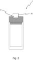
- the Fig. 2 shows a second embodiment of a device 1 of a claimed sanitary fitting in a side view.
- the device 1 has a connecting means 8, which is designed here in the manner of a bayonet lock.
- the connecting means 8 By means of the connecting means 8, the device 1 can be detachably fastened to a dispensing device or sanitary fitting 9 (not shown here in more detail).
- the device 1 can be fastened with the connecting means 8 to a mousseur 18, which is arranged, for example, on or in an outlet opening 13 of the sanitary fitting 9.
- the second embodiment of the device 1 is thus designed in the manner of an adapter, which can be fastened to a dispensing device or sanitary fitting 9 via the connecting means 8.
- the Fig.3 shows the second embodiment of the device 1 in a sectional view.
- the device 1 has a housing 19 to which a container 2 can be detachably attached via a container connection 3, which is designed here in the manner of a bayonet lock.
- the device 1 has a liquid line 4, via which a carbonated liquid can be conducted from a liquid source 5 (not shown here) into the container 2.
- the liquid line 4 extends through the housing 19.
- the device 1 comprises a pressure relief valve 6, which is arranged in a vent line 7.
- the vent line 7 also extends through the housing 19 and connects a receiving space 29 of the container 2 for the carbonated liquid with an environment 28 of the device 1.
- the carbonated liquid flows via the liquid line 4 into the receiving space 29 of the container 2, whereby the pressure in the liquid line 4 and the receiving space 29 increases by compressing the air in the receiving space 29 and at least partially outgassing the carbonated liquid in the receiving space 29.
- a closing force of a spring element 22 on a closing element 21 of the pressure relief valve 6 is overcome, so that the closing element 21 at least partially releases the vent line 7.
- the pressure relief valve 6 can also be operated manually here via a valve actuating lever 20.
- the pressure relief valve 6 is designed here in the manner of a proportional valve, which enables a continuous transition between a closed position and an open position. This makes it possible to avoid a sudden drop in the pressure in the liquid line 4 and the receiving space 29, which could otherwise lead to an undesirably strong foaming of the carbonated liquid in the receiving space 29 of the container 2.
- the present invention enables a carbonated liquid to be filled into a container with a high CO2 concentration and low CO2 consumption.
Landscapes
- Devices For Dispensing Beverages (AREA)
- Filling Of Jars Or Cans And Processes For Cleaning And Sealing Jars (AREA)
Description
Die vorliegende Erfindung betrifft eine Sanitärarmatur zum Befüllen eines Behälters mit einer karbonisierten Flüssigkeit. Die Erfindung dient insbesondere der Bereitstellung kohlensäurehaltiger Getränke in Behältern, wie zum Beispiel Flaschen.The present invention relates to a sanitary fitting for filling a container with a carbonated liquid. The invention is used in particular for providing carbonated drinks in containers, such as bottles.
Bekannt sind Vorrichtungen, Sanitärarmaturen und Verfahren mittels denen in einem Karbonatortopf (trinkbare) Flüssigkeiten, wie zum Beispiel Leitungswasser, unter hohem Druck mit Kohlendioxid (CO2) versetzt werden. Dieses sogenannte Karbonisieren von Flüssigkeiten dient insbesondere der Erhöhung eines Erfrischungseffekts durch die Stimulation von Geschmackssinneszellen beim Trinken. Die karbonisierte Flüssigkeit kann anschließend in einen Behälter, wie zum Beispiel einer Getränkeflasche, abgefüllt werden. Hierzu wird die karbonisierte Flüssigkeit von dem Karbonatortopf über eine Flüssigkeitsleitung dem Behälter zugeführt. Beim Befüllen des Behälters kann der Druck in der Flüssigkeitsleitung und/oder in dem Behälter sinken, sodass das CO2 zumindest teilweise wieder aus der Flüssigkeit entweicht. Daher ist bekannt, den Druck in dem Behälter vor dem Befüllen mit der karbonisierten Flüssigkeit zunächst mit CO2 zu erhöhen, um ein Schäumen der karbonisierten Flüssigkeit und/oder ein entweichen des CO2 beim anschließenden Befüllen des Behälters mit karbonisierter Flüssigkeit zu verhindern. Nachteilig hieran ist jedoch der hohe CO2-Verbrauch. Weiterhin kann in der Flüssigkeitsleitung eine Engstelle ausgebildet sein, um durch den erzeugten Strömungswiderstand beim Befüllen des Behälters den Druck in der Flüssigkeitsleitung vor der Engstelle zu erhöhen. Dies reicht jedoch nicht aus, um einen hohen CO2-Gehalt in der karbonisierten Flüssigkeit nach dem Abfüllen in den Behälter zu gewährleisten. Solche Sanitärarmaturen sind beispielsweise in den Dokumenten
Aufgabe der Erfindung ist es daher, die mit Bezug auf den Stand der Technik geschilderten Probleme zumindest teilweise zu lösen und insbesondere eine Vorrichtung, eine Sanitärarmatur und ein Verfahren zum Befüllen eines Behälters mit einer karbonisierten Flüssigkeit anzugeben, mit denen ein hoher CO2-Gehalt in der karbonisierten Flüssigkeit bei einem geringen CO2-Verbrauch erzielbar ist.The object of the invention is therefore to at least partially solve the problems described with reference to the prior art and in particular to provide a device, a sanitary fitting and to provide a method for filling a container with a carbonated liquid, with which a high CO2 content in the carbonated liquid can be achieved with a low CO2 consumption.
Diese Aufgabe wird gelöst mit einer Sanitärarmatur gemäß den Merkmalen des unabhängigen Patentanspruchs. Eine weitere vorteilhafte Ausgestaltung der Erfindung ist in dem abhängigen Patentanspruch angegeben.This object is achieved with a sanitary fitting according to the features of the independent patent claim. A further advantageous embodiment of the invention is specified in the dependent patent claim.
Darüber hinaus werden die in den Patentansprüchen angegebenen Merkmale in der Beschreibung näher präzisiert und erläutert, wobei weitere bevorzugte Ausgestaltungen der Erfindung dargestellt werden.Furthermore, the features specified in the patent claims are specified and explained in more detail in the description, with further preferred embodiments of the invention being presented.
Hierzu trägt eine Sanitärarmatur gemäß Anspruch 1 mit einer Vorrichtung zum Befüllen eines Behälters mit einer karbonisierten Flüssigkeit bei, die zumindest die folgenden Komponenten aufweist:
- einen Behälteranschluss zum Anschließen des Behälters an die Vorrichtung,
- zumindest eine Flüssigkeitsleitung, über die die karbonisierte Flüssigkeit von einer Flüssigkeitsquelle in den Behälter leitbar ist, und
- zumindest ein Überdruckventil, mit dem ein Solldruck in der Flüssigkeitsleitung beim Befüllen des Behälters einstellbar ist.
- a container connection for connecting the container to the device,
- at least one liquid line through which the carbonated liquid can be fed from a liquid source into the container, and
- at least one pressure relief valve with which a target pressure in the liquid line can be set when filling the container.
Sanitärarmaturen dienen insbesondere der bedarfsgerechten Bereitstellung eines Mischwassers an einer Zapfstelle, einem Spülbecken, einem Waschbecken, einer Dusche und/oder einer Badewanne. Hierzu ist der Sanitärarmatur regelmäßig ein Kaltwasser mit einer Kaltwassertemperatur und ein Warmwasser mit einer Warmwassertemperatur zuführbar. Die Kaltwassertemperatur beträgt insbesondere maximal 25 °C (Celsius), bevorzugt 1 °C bis 25 °C, besonders bevorzugt 5 °C bis 20 °C und/oder die Warmwassertemperatur insbesondere maximal 90 °C, bevorzugt 25 °C bis 90 °C, besonders bevorzugt 55 °C bis 65 °C. Das Kaltwasser und das Warmwasser sind anschließend durch die Sanitärarmatur beispielsweise mittels einem Mischventil oder einer Thermostatkartusche zu einem Mischwasser mit einer gewünschten Mischwassertemperatur mischbar. Zusätzlich kann mit der vorgeschlagenen Sanitärarmatur bzw. der Vorrichtung ein Behälter, wie zum Beispiel eine Getränkeflasche, eine Karaffe oder ein Trinkgefäß, mit einer karbonisierten Flüssigkeit befüllt werden.Sanitary fittings are used in particular to provide mixed water as needed at a tap, a sink, a washbasin, a shower and/or a bathtub. For this purpose, cold water with a cold water temperature and hot water with a hot water temperature can be regularly supplied to the sanitary fitting. The cold water temperature is in particular a maximum of 25 °C (Celsius), preferably 1 °C to 25 °C, particularly preferably 5 °C to 20 °C and/or the hot water temperature is in particular a maximum of 90 °C, preferably 25 °C to 90 °C, particularly preferably 55 °C to 65 °C. The cold water and the hot water can then be mixed by the sanitary fitting, for example by means of a mixing valve or a thermostat cartridge, to form mixed water with a desired mixed water temperature. In addition, the proposed sanitary fitting or device can be used to fill a container, such as a drinks bottle, a carafe or a drinking vessel, with a carbonated liquid.
Hierzu weist die Vorrichtung einen Behälteranschluss zum Anschließen des Behälters an die Vorrichtung auf. Mittels des Behälteranschlusses wird der Behälter insbesondere lösbar an der Vorrichtung befestigt. Hierzu kann der Behälteranschluss beispielsweise nach Art eines Bajonettverschlusses, Schraubverschlusses, Schnappverschlusses oder Klemmverschlusses ausgebildet sein. Weiterhin kann im Bereich des Behälteranschlusses eine Dichtung vorgesehen sein, sodass der Behälter flüssigkeitsdicht und/oder gasdicht mit der Vorrichtung verbindbar ist. Hierdurch können die Vorrichtung und der Behälter ein geschlossenes System bilden.For this purpose, the device has a container connection for connecting the container to the device. The container is attached to the device in a particularly detachable manner by means of the container connection. For this purpose, the container connection can be designed, for example, in the manner of a bayonet closure, screw closure, snap closure or clamp closure. Furthermore, a seal can be provided in the area of the container connection so that the container can be connected to the device in a liquid-tight and/or gas-tight manner. This allows the device and the container to form a closed system.
Weiterhin umfasst die Vorrichtung zumindest eine Flüssigkeitsleitung, über die die karbonisierte Flüssigkeit von einer Flüssigkeitsquelle in den Behälter leitbar ist. Bei der Flüssigkeitsquelle kann es sich beispielsweise um einen Vorratsbehälter für die karbonisierte Flüssigkeit oder eine Karbonisierungsvorrichtung zum Karbonisieren einer Flüssigkeit, beispielsweise nach Art eines Karbonatortopfs, handeln. Mittels der Karbonisierungsvorrichtung ist die Flüssigkeit insbesondere unter hohem Druck CO2 zuführbar, sodass sich das CO2 in der Flüssigkeit löst. Die zumindest eine Flüssigkeitsleitung erstreckt sich bevorzugt von der Flüssigkeitsquelle durch den Behälteranschluss in den Behälter. Alternativ kann sich die zumindest eine Flüssigkeitsleitung von der Flüssigkeitsquelle zu der Auslauföffnung der Zapfvorrichtung bzw. Sanitärarmatur erstrecken.The device further comprises at least one liquid line, via which the carbonated liquid can be conducted from a liquid source into the container. The liquid source can be, for example, a storage container for the carbonated liquid or a carbonation device for carbonating a liquid, for example in the manner of a carbonator pot. The liquid can be supplied with CO2, in particular under high pressure, by means of the carbonation device, so that the CO2 dissolves in the liquid. The at least one liquid line preferably extends from the liquid source through the container connection into the container. Alternatively, the at least one liquid line can extend from the liquid source to the outlet opening of the dispensing device or sanitary fitting.
Darüber hinaus weist die Vorrichtung zumindest ein Überdruckventil auf, mit dem ein Solldruck in der Flüssigkeitsleitung beim Befüllen des Behälters einstellbar ist. Hierzu kann das zumindest eine Überdruckventil zumindest teilweise geschlossen sein, solange ein Leitungsdruck in der Flüssigkeitsleitung geringer ist als der Solldruck. Das zumindest eine Überdruckventil ist, in der Flüssigkeitsleitung oder in einer Entlüftungsleitung zur Entlüftung des Behälters angeordnet. Weiterhin kann das zumindest eine Überdruckventil ein mit einer Federkraft belastetes Schließelement aufweisen, wobei die Federkraft auf den gewünschten Solldruck angepasst und/oder (variabel) anpassbar ist. Der Solldruck kann beispielsweise 1 bar bis 20 bar, bevorzugt 1 bar bis 8 bar betragen. Alternativ kann das Überdruckventil auch elektronisch steuerbar sein. Hierzu kann der Leitungsdruck in der zumindest einen Flüssigkeitsleitung beispielsweise mittels eines Drucksensors messbar sein, wobei der Drucksensor datenleitend mit einer Steuerung verbunden ist. Bei Erreichen des Solldrucks öffnet die Steuerung das zumindest eine Überdruckventil zumindest teilweise, sodass der Solldruck in der zumindest einen Flüssigkeitsleitung im Wesentlichen gehalten wird. Vor dem Befüllen des Behälters herrscht in dem Behälter insbesondere ein Umgebungsdruck von beispielsweise ca. 1 bar. Zu Beginn eines Befüllprozesses steigt der Druck in der Flüssigkeitsleitung durch den (statischen) Druck in der Flüssigkeitsquelle bzw. ein Öffnen eines Ventils der Flüssigkeitsquelle und/oder durch ein Pumpen der karbonisierten Flüssigkeit durch die Flüssigkeitsleitung mit einer Pumpe an. Bei Erreichen des Solldrucks kann sich das zumindest eine Überdruckventil zumindest teilweise öffnen. Ist das zumindest eine Überdruckventil in der Flüssigkeitsleitung angeordnet, wird die Flüssigkeitsleitung durch das zumindest eine Überdruckventil bei Erreichen des Solldrucks zumindest teilweise freigegeben, sodass die karbonisierte Flüssigkeit durch die Flüssigkeitsleitung in den Behälter fließen kann und/oder der Leitungsdruck in der Flüssigkeitsleitung nicht über einen maximal zulässigen Druck steigt. Ist das zumindest eine Überdruckventil in der Entlüftungsleitung angeordnet, fließt die karbonisierte Flüssigkeit durch die Flüssigkeitsleitung in den Behälter, sodass der Druck in der Flüssigkeitsleitung und dem Behälter infolge einer Kompression der in dem Behälter befindlichen Luft und/oder ein zumindest teilweises Entgasen der karbonisierten Flüssigkeit in dem Behälter steigt, bis der Druck den Solldruck erreicht. Bei Erreichen des Solldrucks öffnet sich das zumindest eine Druckventil zumindest teilweise, sodass der Druck in der Flüssigkeitsleitung und/oder in dem Behälter nicht über einen maximal zulässigen Druck steigt. Insbesondere gibt das Schließelement des zumindest einen Überdruckventils bei Erreichen des Solldrucks nach, sodass die Flüssigkeitsleitung und/oder die Entlüftungsleitung zumindest teilweise freigegeben wird. Sinkt der Leitungsdruck in der Flüssigkeitsleitung und/oder der Druck in dem Behälter während des Befüllens des Behälters oder nach dem Befüllen des Behälters unter den Solldruck, schließt sich das zumindest eine Überdruckventil zumindest teilweise, sodass der Leitungsdruck in der Flüssigkeitsleitung bzw. der Druck in dem Behälter gehalten wird oder wieder bis zu dem Solldruck ansteigt. Mit dem zumindest einen Überdruckventil kann der Leitungsdruck in der Flüssigkeitsleitung und/oder der Druck in dem Behälter während des Befüllens des Behälters mit der karbonisierten Flüssigkeit insbesondere (im Wesentlichen) konstant gehalten werden. Somit ist mit dem zumindest einen Überdruckventil gewährleistbar, dass ein Leitungsdruck in der Flüssigkeitsleitung und/oder der Druck in dem Behälter während des Befüllens des Behälters mit der karbonisierten Flüssigkeit im Wesentlichen dem Solldruck entspricht, sodass ein Entgasen der karbonisierten Flüssigkeit verhinderbar ist. Die karbonisierte Flüssigkeit ist hierdurch mit einem geringen CO2-Verbrauch und einer hohen CO2-Konzentration in den Behälter füllbar. Nach dem Befüllen des Behälters ist der Behälter von dem Behälteranschluss entfernbar bzw. lösbar und beispielsweise als Karaffe nutzbar.In addition, the device has at least one pressure relief valve with which a target pressure in the liquid line can be set when filling the container. For this purpose, the at least a pressure relief valve must be at least partially closed as long as a line pressure in the liquid line is lower than the target pressure. The at least one pressure relief valve is arranged in the liquid line or in a vent line for venting the container. Furthermore, the at least one pressure relief valve can have a closing element loaded with a spring force, wherein the spring force is adapted to the desired target pressure and/or is (variably) adaptable. The target pressure can be, for example, 1 bar to 20 bar, preferably 1 bar to 8 bar. Alternatively, the pressure relief valve can also be electronically controlled. For this purpose, the line pressure in the at least one liquid line can be measured, for example, by means of a pressure sensor, wherein the pressure sensor is connected to a controller in a data-conducting manner. When the target pressure is reached, the controller opens the at least one pressure relief valve at least partially, so that the target pressure in the at least one liquid line is essentially maintained. Before the container is filled, there is in particular an ambient pressure of, for example, approximately 1 bar in the container. At the start of a filling process, the pressure in the liquid line increases due to the (static) pressure in the liquid source or opening a valve of the liquid source and/or by pumping the carbonated liquid through the liquid line with a pump. When the target pressure is reached, the at least one pressure relief valve can open at least partially. If the at least one pressure relief valve is arranged in the liquid line, the liquid line is at least partially released by the at least one pressure relief valve when the target pressure is reached, so that the carbonated liquid can flow through the liquid line into the container and/or the line pressure in the liquid line does not rise above a maximum permissible pressure. If the at least one pressure relief valve is arranged in the vent line, the carbonated liquid flows through the liquid line into the container, so that the pressure in the liquid line and the container increases as a result of compression of the air in the container and/or at least partial degassing of the carbonated liquid in the container until the pressure reaches the target pressure. When the target pressure is reached, the at least one pressure valve opens at least partially so that the pressure in the liquid line and/or in the container does not rise above a maximum permissible pressure. In particular, the closing element of the at least one pressure relief valve when the target pressure is reached, so that the liquid line and/or the vent line is at least partially released. If the line pressure in the liquid line and/or the pressure in the container drops below the target pressure during filling of the container or after filling of the container, the at least one pressure relief valve closes at least partially, so that the line pressure in the liquid line or the pressure in the container is maintained or rises again to the target pressure. With the at least one pressure relief valve, the line pressure in the liquid line and/or the pressure in the container can be kept (substantially) constant during filling of the container with the carbonated liquid. Thus, with the at least one pressure relief valve it can be ensured that a line pressure in the liquid line and/or the pressure in the container during filling of the container with the carbonated liquid essentially corresponds to the target pressure, so that degassing of the carbonated liquid can be prevented. This means that the carbonated liquid can be filled into the container with low CO2 consumption and a high CO2 concentration. After filling the container, the container can be removed or detached from the container connection and used as a carafe, for example.
Das zumindest eine Überdruckventil kann ein Schließelement aufweisen, dass durch ein Federelement derart mit einer Schließkraft beaufschlagt ist, dass sich das zumindest eine Überdruckventil bei einem Solldruck öffnet, der niedriger als ein Druck in der Flüssigkeitsquelle ist. Hierdurch kann gewährleistet werden, dass der Druck in der Flüssigkeitsquelle ausreicht, um das zumindest eine Überdruckventil zu öffnen.The at least one pressure relief valve can have a closing element that is subjected to a closing force by a spring element such that the at least one pressure relief valve opens at a target pressure that is lower than a pressure in the liquid source. This can ensure that the pressure in the liquid source is sufficient to open the at least one pressure relief valve.
Der Solldruck kann mindestens 0,1 bar niedriger als der Druck in der Flüssigkeitsquelle sein. Insbesondere kann der Solldruck 0,5 bis 1 bar niedriger als der Druck in der Flüssigkeitsquelle sein. Hierdurch kann gewährleistet werden, dass der Durchfluss durch die Flüssigkeitsleitung nicht zu hoch ist, sodass Verwirbelungen der karbonisierten Flüssigkeit verhinderbar sind.The target pressure can be at least 0.1 bar lower than the pressure in the liquid source. In particular, the target pressure can be 0.5 to 1 bar lower than the pressure in the liquid source. This ensures that the flow through the liquid line is not too high, so that turbulence in the carbonated liquid can be prevented.
Das zumindest eine Überdruckventil kann in einer Entlüftungsleitung des Behälters angeordnet sein. Die Entlüftungsleitung verbindet insbesondere einen Aufnahmeraum des Behälters für die karbonisierte Flüssigkeit mit einer Umgebung der Vorrichtung. Hierzu erstreckt sich die Entlüftungsleitung bevorzugt von dem Aufnahmeraum des Behälters durch den Behälteranschluss zu der Umgebung der Vorrichtung. Durch die Entlüftungsleitung ist Luft und/oder CO2 aus dem Aufnahmeraum in die Umgebung bzw. Atmosphäre ableitbar. Wenn die Vorrichtung nach Art eines Adapters ausgebildet ist, kann die Entlüftungsleitung teilweise in dem Adapter und teilweise in der Zapfvorrichtung ausgebildet sein. Das zumindest eine Überdruckventil kann in diesem Fall in dem Adapter oder der Zapfvorrichtung angeordnet sein.The at least one pressure relief valve can be arranged in a vent line of the container. The vent line connects in particular a receiving space of the container for the carbonated liquid with an environment of the device. For this purpose, the vent line preferably extends from the receiving space of the container through the container connection to the environment of the device. Air and/or CO2 can be discharged from the receiving space into the environment or atmosphere through the vent line. If the device is designed in the manner of an adapter, the vent line can be formed partly in the adapter and partly in the dispensing device. The at least one pressure relief valve can in this case be arranged in the adapter or the dispensing device.
Weiterhin kann das zumindest eine Überdruckventil in der Flüssigkeitsleitung angeordnet sein. Insbesondere ist das zumindest eine Überdruckventil an einem Ende der Flüssigkeitsleitung angeordnet, mit dem die Flüssigkeitsleitung in den Behälter oder die Auslauföffnung der Zapfvorrichtung bzw. Sanitärarmatur mündet. Bevorzugt ist das zumindest eine Überdruckventil entlang der Flüssigkeitsleitung maximal 10 cm (Zentimeter) stromaufwärts des Endes der Flüssigkeitsleitung oder der Auslauföffnung in der Flüssigkeitsleitung angeordnet.Furthermore, the at least one pressure relief valve can be arranged in the liquid line. In particular, the at least one pressure relief valve is arranged at one end of the liquid line with which the liquid line opens into the container or the outlet opening of the dispensing device or sanitary fitting. Preferably, the at least one pressure relief valve is arranged along the liquid line a maximum of 10 cm (centimeters) upstream of the end of the liquid line or the outlet opening in the liquid line.
Das zumindest eine Überdruckventil kann schließen, wenn ein Leitungsdruck in der Flüssigkeitsleitung niedriger als der Solldruck ist.The at least one pressure relief valve can close when a line pressure in the liquid line is lower than the target pressure.
Das zumindest eine Überdruckventil kann öffnen, wenn ein Leitungsdruck in der Flüssigkeitsleitung den Solldruck erreicht.At least one pressure relief valve can open when a line pressure in the liquid line reaches the target pressure.
Der Erfindung folgend wird eine Sanitärarmatur angegeben, die zumindest die folgenden Komponenten aufweist:
- ein Armaturengehäuse mit einem Auslauf,
- eine Flüssigkeitsquelle für eine karbonisierte Flüssigkeit, und
- eine hier vorgeschlagene Vorrichtung.
- a faucet housing with a spout,
- a liquid source for a carbonated liquid, and
- a device proposed here.
Bezüglich der Einzelheiten der Sanitärarmatur wird auf die Beschreibung der Vorrichtung verwiesen.For details of the sanitary fitting, please refer to the description of the device.
Einem noch weiteren Aspekt der Offenbarung folgend wird auch ein Verfahren zum Befüllen eines Behälters mit einer karbonisierten Flüssigkeit angegeben, das zumindest die folgenden Schritte aufweist:
- a) Bereitstellen der karbonisierten Flüssigkeit in einer Flüssigkeitsquelle,
- b) Befüllen des Behälters mit der karbonisierten Flüssigkeit aus der Flüssigkeitsquelle über zumindest eine Flüssigkeitsleitung, und
- c) Einstellen eines Solldrucks in der Flüssigkeitsleitung mithilfe zumindest eines Überdruckventils.
- a) Providing the carbonated liquid in a liquid source,
- b) filling the container with the carbonated liquid from the liquid source via at least one liquid line, and
- c) Setting a target pressure in the liquid line by means of at least one pressure relief valve.
Bezüglich der Einzelheiten des Verfahrens kann die Beschreibung der Vorrichtung in Bezug genommen werden.For details of the method, reference can be made to the description of the device.
Die Erfindung sowie das technische Umfeld werden nachfolgend anhand der Figuren näher erläutert. Es ist darauf hinzuweisen, dass die Figuren besonders bevorzugte Ausführungsvarianten der Erfindung zeigen, diese jedoch nicht darauf beschränkt ist. Dabei sind gleiche Bauteile in den Figuren mit denselben Bezugszeichen versehen. Es zeigen beispielhaft und schematisch:
-
Fig. 1 : eine nicht von den Ansprüchen umfasste Sanitärarmatur mit einer ersten Ausführungsvariante einer Vorrichtung; -
Fig. 2 : eine zweite Ausführungsvariante einer Sanitärarmatur mit einer Vorrichtung in einer Seitenansicht; diese Sanitärarmatur ist von den Ansprüchen umfasst. Und -
Fig. 3 : die Vorrichtung in einer Schnittdarstellung.
-
Fig.1 : a sanitary fitting not covered by the claims with a first embodiment of a device; -
Fig. 2 : a second embodiment of a sanitary fitting with a device in a side view; this sanitary fitting is covered by the claims. And -
Fig.3 : the device in a sectional view.
Die
Die
Die
Durch die vorliegende Erfindung ist eine karbonisierte Flüssigkeit bei einem geringen CO2-Verbrauch mit einer hohen CO2-Konzentration in einen Behälter abfüllbar.The present invention enables a carbonated liquid to be filled into a container with a high CO2 concentration and low CO2 consumption.
- 11
- Vorrichtungdevice
- 22
- Behältercontainer
- 33
- BehälteranschlussContainer connection
- 44
- FlüssigkeitsleitungLiquid line
- 55
- FlüssigkeitsquelleFluid source
- 66
- ÜberdruckventilPressure relief valve
- 77
- EntlüftungsleitungVent line
- 88
- VerbindungsmittelConnecting elements
- 99
- SanitärarmaturSanitary fitting
- 1010
- ArmaturengehäuseValve housing
- 1111
- AuslaufOutlet
- 1212
- Hebellever
- 1313
- AuslauföffnungOutlet opening
- 1414
- MischventilMixing valve
- 1515
- WarmwasserquelleHot water source
- 1616
- KaltwasserquelleCold water spring
- 1717
- CO2-QuelleCO2 source
- 1818
- MousseurMousseur
- 1919
- GehäuseHousing
- 2020
- VentilbetätigungshebelValve operating lever
- 2121
- SchließelementLocking element
- 2222
- FederelementSpring element
- 2323
- Trägercarrier
- 2424
- KaltwasserleitungCold water pipe
- 2525
- CO2-LeitungCO2 line
- 2626
- WarmwasserleitungHot water pipe
- 2727
- MischwasserleitungCombined water pipe
- 2828
- UmgebungVicinity
- 2929
- AufnahmeraumRecording room
Claims (2)
- A sanitary fitting (9), comprising at least:- a faucet housing (10) with an outlet (11),- a liquid source (5) for a carbonated liquid, and- a device (1) for filling a container (2) with a carbonated liquid, comprising at least: a housing (19), a container connection (3) for detachably attaching the container (2) to the housing (19), at least one liquid line (4) which extends through the housing (19) andvia which the carbonated liquid can be conducted from the liquid source (5) into the container (2), at least one pressure relief valve (6) with which a target pressure in the liquid line (4) can be adjusted when filling the container (2), wherein the device (1) can be detachably attached to the outlet (11) by means of a connecting means (8) of the sanitary fitting, wherein the at least one pressure relief valve (6) is arranged in the liquid line (4), or wherein the at least one pressure relief valve (6) is arranged in a vent line (7) which extends through the housing (19) for venting the container (2).
- The sanitary fitting (9) according to claim 1, wherein the connecting means (8) is designed in the manner of a bayonet lock.
Applications Claiming Priority (1)
| Application Number | Priority Date | Filing Date | Title |
|---|---|---|---|
| DE102018107605.3A DE102018107605A1 (en) | 2018-03-29 | 2018-03-29 | Device, sanitary fitting and method for filling a container with a carbonated liquid |
Publications (2)
| Publication Number | Publication Date |
|---|---|
| EP3546422A1 EP3546422A1 (en) | 2019-10-02 |
| EP3546422B1 true EP3546422B1 (en) | 2024-09-25 |
Family
ID=65903953
Family Applications (1)
| Application Number | Title | Priority Date | Filing Date |
|---|---|---|---|
| EP19163736.2A Active EP3546422B1 (en) | 2018-03-29 | 2019-03-19 | Sanitary device |
Country Status (4)
| Country | Link |
|---|---|
| US (1) | US20190300356A1 (en) |
| EP (1) | EP3546422B1 (en) |
| CN (1) | CN110316685B (en) |
| DE (1) | DE102018107605A1 (en) |
Families Citing this family (4)
| Publication number | Priority date | Publication date | Assignee | Title |
|---|---|---|---|---|
| DE102019104229A1 (en) * | 2019-02-20 | 2020-08-20 | Grohe Ag | Device and sanitary fitting for filling a container with a carbonized liquid |
| DE102020108554A1 (en) | 2020-03-27 | 2021-09-30 | Grohe Ag | Dispenser cartridge |
| DE102022106836A1 (en) * | 2022-03-23 | 2023-09-28 | Grohe Ag | Device and method for producing a carbonated liquid |
| EP4685297A1 (en) * | 2024-07-23 | 2026-01-28 | Zerica S.r.l. | A system for dispensing water and adding a gas thereto and a relative method |
Family Cites Families (10)
| Publication number | Priority date | Publication date | Assignee | Title |
|---|---|---|---|---|
| DE3510412A1 (en) * | 1985-03-22 | 1986-09-25 | Gea Ahlborn Gmbh & Co Kg, 3203 Sarstedt | Installation for the continuous pasteurisation and drawing off of beer and other drinks containing gas |
| US5139058A (en) * | 1988-10-12 | 1992-08-18 | Crown Cork & Seal Company, Inc. | Filling valve |
| GB2251674A (en) * | 1990-12-22 | 1992-07-15 | Rudge H E & Co Ltd | Fluid supply fittings |
| DE19849628A1 (en) * | 1998-10-28 | 2000-05-04 | Margret Spiegel | Method and arrangement for introducing gas into a liquid |
| DE102007009435A1 (en) * | 2007-02-23 | 2008-08-28 | Khs Ag | Method for filling bottles or the like container with a liquid product under counter pressure and filling machine for performing this method |
| US9315977B1 (en) * | 2013-01-07 | 2016-04-19 | Joelex, Inc. | Valve apparatus for regulating fluids through a pipe |
| US9114368B2 (en) * | 2013-03-08 | 2015-08-25 | Cornelius, Inc. | Batch carbonator and method of forming a carbonated beverage |
| WO2015006588A1 (en) * | 2013-07-10 | 2015-01-15 | As Ip Holdco, Llc | Faucet-integrated carbonation systems and methods |
| EP2987607B1 (en) * | 2014-08-20 | 2017-06-07 | Krones AG | Moulding and filling method |
| DE102014014317B4 (en) * | 2014-10-01 | 2018-06-07 | Leibinger Gmbh | Device and method for measuring medium-free filling of a container |
-
2018
- 2018-03-29 DE DE102018107605.3A patent/DE102018107605A1/en not_active Withdrawn
-
2019
- 2019-03-19 EP EP19163736.2A patent/EP3546422B1/en active Active
- 2019-03-28 CN CN201910242852.4A patent/CN110316685B/en not_active Expired - Fee Related
- 2019-03-29 US US16/370,120 patent/US20190300356A1/en not_active Abandoned
Also Published As
| Publication number | Publication date |
|---|---|
| CN110316685B (en) | 2022-05-17 |
| EP3546422A1 (en) | 2019-10-02 |
| DE102018107605A1 (en) | 2019-10-02 |
| CN110316685A (en) | 2019-10-11 |
| US20190300356A1 (en) | 2019-10-03 |
Similar Documents
| Publication | Publication Date | Title |
|---|---|---|
| EP3546422B1 (en) | Sanitary device | |
| EP3674256B1 (en) | Dispenser with a cartridge holder | |
| DE102004007727A1 (en) | Conventional carbonator systems or impregnation systems in addition at least one hollow body inline impregnator filled with bulk material to nachkarbonisieren or impregnate already carbonated or impregnated liquids | |
| DE2531697A1 (en) | DEVICE FOR DISPENSING LIQUIDS | |
| DE102012100844A1 (en) | Carbonating device for wine and wine-based drinks | |
| DE202024100624U1 (en) | Mixing device | |
| DE1532614A1 (en) | Valve unit for a liquid container | |
| EP3927647B1 (en) | Device and sanitary fitting for filling a container with a carbonated liquid | |
| EP2236198A2 (en) | Device for issuing beverages | |
| DE102020215036A1 (en) | Bubble machine | |
| EP0141834A1 (en) | Method for supplying draught-beer, particularly "weissbier", into drinking glasses | |
| DE46809C (en) | Filling tap | |
| DE202020107037U1 (en) | CO2 gas supply by means of an aquarium pressurized gas container with a nutrient substrate | |
| DE2306406A1 (en) | Flow rate control for cream pump - by double seat nonreturn valve for air and cream inlets | |
| AT527207B1 (en) | Device for dispensing a carbonated beverage | |
| AT527206B1 (en) | Device for dispensing a carbonated beverage | |
| DE52233C (en) | Shower bath facility | |
| DE958388C (en) | Filling and extraction valve | |
| DE127326C (en) | ||
| DE199972C (en) | ||
| WO2017012992A1 (en) | Device for introducing gases into liquids | |
| DE234490C (en) | ||
| WO2023198660A1 (en) | Pressure equalization vessel and arrangement | |
| DE577313C (en) | Flushing system with automatically closing flushing valves | |
| DE10002335A1 (en) | Device for impregnating liquids with a gas |
Legal Events
| Date | Code | Title | Description |
|---|---|---|---|
| PUAI | Public reference made under article 153(3) epc to a published international application that has entered the european phase |
Free format text: ORIGINAL CODE: 0009012 |
|
| STAA | Information on the status of an ep patent application or granted ep patent |
Free format text: STATUS: THE APPLICATION HAS BEEN PUBLISHED |
|
| AK | Designated contracting states |
Kind code of ref document: A1 Designated state(s): AL AT BE BG CH CY CZ DE DK EE ES FI FR GB GR HR HU IE IS IT LI LT LU LV MC MK MT NL NO PL PT RO RS SE SI SK SM TR |
|
| AX | Request for extension of the european patent |
Extension state: BA ME |
|
| STAA | Information on the status of an ep patent application or granted ep patent |
Free format text: STATUS: REQUEST FOR EXAMINATION WAS MADE |
|
| 17P | Request for examination filed |
Effective date: 20200402 |
|
| RBV | Designated contracting states (corrected) |
Designated state(s): AL AT BE BG CH CY CZ DE DK EE ES FI FR GB GR HR HU IE IS IT LI LT LU LV MC MK MT NL NO PL PT RO RS SE SI SK SM TR |
|
| STAA | Information on the status of an ep patent application or granted ep patent |
Free format text: STATUS: EXAMINATION IS IN PROGRESS |
|
| 17Q | First examination report despatched |
Effective date: 20210305 |
|
| RAP3 | Party data changed (applicant data changed or rights of an application transferred) |
Owner name: GROHE AG |
|
| GRAP | Despatch of communication of intention to grant a patent |
Free format text: ORIGINAL CODE: EPIDOSNIGR1 |
|
| STAA | Information on the status of an ep patent application or granted ep patent |
Free format text: STATUS: GRANT OF PATENT IS INTENDED |
|
| INTG | Intention to grant announced |
Effective date: 20240626 |
|
| GRAS | Grant fee paid |
Free format text: ORIGINAL CODE: EPIDOSNIGR3 |
|
| GRAA | (expected) grant |
Free format text: ORIGINAL CODE: 0009210 |
|
| STAA | Information on the status of an ep patent application or granted ep patent |
Free format text: STATUS: THE PATENT HAS BEEN GRANTED |
|
| AK | Designated contracting states |
Kind code of ref document: B1 Designated state(s): AL AT BE BG CH CY CZ DE DK EE ES FI FR GB GR HR HU IE IS IT LI LT LU LV MC MK MT NL NO PL PT RO RS SE SI SK SM TR |
|
| REG | Reference to a national code |
Ref country code: GB Ref legal event code: FG4D Free format text: NOT ENGLISH |
|
| REG | Reference to a national code |
Ref country code: CH Ref legal event code: EP |
|
| REG | Reference to a national code |
Ref country code: DE Ref legal event code: R096 Ref document number: 502019012172 Country of ref document: DE |
|
| REG | Reference to a national code |
Ref country code: IE Ref legal event code: FG4D Free format text: LANGUAGE OF EP DOCUMENT: GERMAN |
|
| P01 | Opt-out of the competence of the unified patent court (upc) registered |
Free format text: CASE NUMBER: APP_57172/2024 Effective date: 20241018 |
|
| REG | Reference to a national code |
Ref country code: LT Ref legal event code: MG9D |
|
| PG25 | Lapsed in a contracting state [announced via postgrant information from national office to epo] |
Ref country code: NO Free format text: LAPSE BECAUSE OF FAILURE TO SUBMIT A TRANSLATION OF THE DESCRIPTION OR TO PAY THE FEE WITHIN THE PRESCRIBED TIME-LIMIT Effective date: 20241225 |
|
| PG25 | Lapsed in a contracting state [announced via postgrant information from national office to epo] |
Ref country code: GR Free format text: LAPSE BECAUSE OF FAILURE TO SUBMIT A TRANSLATION OF THE DESCRIPTION OR TO PAY THE FEE WITHIN THE PRESCRIBED TIME-LIMIT Effective date: 20241226 Ref country code: FI Free format text: LAPSE BECAUSE OF FAILURE TO SUBMIT A TRANSLATION OF THE DESCRIPTION OR TO PAY THE FEE WITHIN THE PRESCRIBED TIME-LIMIT Effective date: 20240925 |
|
| PG25 | Lapsed in a contracting state [announced via postgrant information from national office to epo] |
Ref country code: BG Free format text: LAPSE BECAUSE OF FAILURE TO SUBMIT A TRANSLATION OF THE DESCRIPTION OR TO PAY THE FEE WITHIN THE PRESCRIBED TIME-LIMIT Effective date: 20240925 |
|
| PG25 | Lapsed in a contracting state [announced via postgrant information from national office to epo] |
Ref country code: LV Free format text: LAPSE BECAUSE OF FAILURE TO SUBMIT A TRANSLATION OF THE DESCRIPTION OR TO PAY THE FEE WITHIN THE PRESCRIBED TIME-LIMIT Effective date: 20240925 |
|
| PG25 | Lapsed in a contracting state [announced via postgrant information from national office to epo] |
Ref country code: RS Free format text: LAPSE BECAUSE OF FAILURE TO SUBMIT A TRANSLATION OF THE DESCRIPTION OR TO PAY THE FEE WITHIN THE PRESCRIBED TIME-LIMIT Effective date: 20241225 |
|
| REG | Reference to a national code |
Ref country code: NL Ref legal event code: MP Effective date: 20240925 |
|
| PG25 | Lapsed in a contracting state [announced via postgrant information from national office to epo] |
Ref country code: RS Free format text: LAPSE BECAUSE OF FAILURE TO SUBMIT A TRANSLATION OF THE DESCRIPTION OR TO PAY THE FEE WITHIN THE PRESCRIBED TIME-LIMIT Effective date: 20241225 Ref country code: NO Free format text: LAPSE BECAUSE OF FAILURE TO SUBMIT A TRANSLATION OF THE DESCRIPTION OR TO PAY THE FEE WITHIN THE PRESCRIBED TIME-LIMIT Effective date: 20241225 Ref country code: LV Free format text: LAPSE BECAUSE OF FAILURE TO SUBMIT A TRANSLATION OF THE DESCRIPTION OR TO PAY THE FEE WITHIN THE PRESCRIBED TIME-LIMIT Effective date: 20240925 Ref country code: GR Free format text: LAPSE BECAUSE OF FAILURE TO SUBMIT A TRANSLATION OF THE DESCRIPTION OR TO PAY THE FEE WITHIN THE PRESCRIBED TIME-LIMIT Effective date: 20241226 Ref country code: FI Free format text: LAPSE BECAUSE OF FAILURE TO SUBMIT A TRANSLATION OF THE DESCRIPTION OR TO PAY THE FEE WITHIN THE PRESCRIBED TIME-LIMIT Effective date: 20240925 Ref country code: BG Free format text: LAPSE BECAUSE OF FAILURE TO SUBMIT A TRANSLATION OF THE DESCRIPTION OR TO PAY THE FEE WITHIN THE PRESCRIBED TIME-LIMIT Effective date: 20240925 |
|
| PG25 | Lapsed in a contracting state [announced via postgrant information from national office to epo] |
Ref country code: NL Free format text: LAPSE BECAUSE OF FAILURE TO SUBMIT A TRANSLATION OF THE DESCRIPTION OR TO PAY THE FEE WITHIN THE PRESCRIBED TIME-LIMIT Effective date: 20240925 |
|
| PG25 | Lapsed in a contracting state [announced via postgrant information from national office to epo] |
Ref country code: PT Free format text: LAPSE BECAUSE OF FAILURE TO SUBMIT A TRANSLATION OF THE DESCRIPTION OR TO PAY THE FEE WITHIN THE PRESCRIBED TIME-LIMIT Effective date: 20250127 Ref country code: IS Free format text: LAPSE BECAUSE OF FAILURE TO SUBMIT A TRANSLATION OF THE DESCRIPTION OR TO PAY THE FEE WITHIN THE PRESCRIBED TIME-LIMIT Effective date: 20250125 |
|
| PG25 | Lapsed in a contracting state [announced via postgrant information from national office to epo] |
Ref country code: RO Free format text: LAPSE BECAUSE OF FAILURE TO SUBMIT A TRANSLATION OF THE DESCRIPTION OR TO PAY THE FEE WITHIN THE PRESCRIBED TIME-LIMIT Effective date: 20240925 Ref country code: SM Free format text: LAPSE BECAUSE OF FAILURE TO SUBMIT A TRANSLATION OF THE DESCRIPTION OR TO PAY THE FEE WITHIN THE PRESCRIBED TIME-LIMIT Effective date: 20240925 |
|
| PG25 | Lapsed in a contracting state [announced via postgrant information from national office to epo] |
Ref country code: ES Free format text: LAPSE BECAUSE OF FAILURE TO SUBMIT A TRANSLATION OF THE DESCRIPTION OR TO PAY THE FEE WITHIN THE PRESCRIBED TIME-LIMIT Effective date: 20240925 |
|
| PG25 | Lapsed in a contracting state [announced via postgrant information from national office to epo] |
Ref country code: EE Free format text: LAPSE BECAUSE OF FAILURE TO SUBMIT A TRANSLATION OF THE DESCRIPTION OR TO PAY THE FEE WITHIN THE PRESCRIBED TIME-LIMIT Effective date: 20240925 |
|
| PG25 | Lapsed in a contracting state [announced via postgrant information from national office to epo] |
Ref country code: CZ Free format text: LAPSE BECAUSE OF FAILURE TO SUBMIT A TRANSLATION OF THE DESCRIPTION OR TO PAY THE FEE WITHIN THE PRESCRIBED TIME-LIMIT Effective date: 20240925 Ref country code: PL Free format text: LAPSE BECAUSE OF FAILURE TO SUBMIT A TRANSLATION OF THE DESCRIPTION OR TO PAY THE FEE WITHIN THE PRESCRIBED TIME-LIMIT Effective date: 20240925 |
|
| PG25 | Lapsed in a contracting state [announced via postgrant information from national office to epo] |
Ref country code: SK Free format text: LAPSE BECAUSE OF FAILURE TO SUBMIT A TRANSLATION OF THE DESCRIPTION OR TO PAY THE FEE WITHIN THE PRESCRIBED TIME-LIMIT Effective date: 20240925 |
|
| REG | Reference to a national code |
Ref country code: DE Ref legal event code: R097 Ref document number: 502019012172 Country of ref document: DE |
|
| PG25 | Lapsed in a contracting state [announced via postgrant information from national office to epo] |
Ref country code: DK Free format text: LAPSE BECAUSE OF FAILURE TO SUBMIT A TRANSLATION OF THE DESCRIPTION OR TO PAY THE FEE WITHIN THE PRESCRIBED TIME-LIMIT Effective date: 20240925 |
|
| PLBE | No opposition filed within time limit |
Free format text: ORIGINAL CODE: 0009261 |
|
| STAA | Information on the status of an ep patent application or granted ep patent |
Free format text: STATUS: NO OPPOSITION FILED WITHIN TIME LIMIT |
|
| 26N | No opposition filed |
Effective date: 20250626 |
|
| PG25 | Lapsed in a contracting state [announced via postgrant information from national office to epo] |
Ref country code: SE Free format text: LAPSE BECAUSE OF FAILURE TO SUBMIT A TRANSLATION OF THE DESCRIPTION OR TO PAY THE FEE WITHIN THE PRESCRIBED TIME-LIMIT Effective date: 20240925 |
|
| REG | Reference to a national code |
Ref country code: DE Ref legal event code: R119 Ref document number: 502019012172 Country of ref document: DE |
|
| PG25 | Lapsed in a contracting state [announced via postgrant information from national office to epo] |
Ref country code: MC Free format text: LAPSE BECAUSE OF FAILURE TO SUBMIT A TRANSLATION OF THE DESCRIPTION OR TO PAY THE FEE WITHIN THE PRESCRIBED TIME-LIMIT Effective date: 20240925 |
|
| REG | Reference to a national code |
Ref country code: CH Ref legal event code: H13 Free format text: ST27 STATUS EVENT CODE: U-0-0-H10-H13 (AS PROVIDED BY THE NATIONAL OFFICE) Effective date: 20251023 |
|
| PG25 | Lapsed in a contracting state [announced via postgrant information from national office to epo] |
Ref country code: LU Free format text: LAPSE BECAUSE OF NON-PAYMENT OF DUE FEES Effective date: 20250319 |
|
| GBPC | Gb: european patent ceased through non-payment of renewal fee |
Effective date: 20250319 |
|
| REG | Reference to a national code |
Ref country code: BE Ref legal event code: MM Effective date: 20250331 |
|
| PG25 | Lapsed in a contracting state [announced via postgrant information from national office to epo] |
Ref country code: DE Free format text: LAPSE BECAUSE OF NON-PAYMENT OF DUE FEES Effective date: 20251001 |
|
| PG25 | Lapsed in a contracting state [announced via postgrant information from national office to epo] |
Ref country code: GB Free format text: LAPSE BECAUSE OF NON-PAYMENT OF DUE FEES Effective date: 20250319 |
|
| PG25 | Lapsed in a contracting state [announced via postgrant information from national office to epo] |
Ref country code: HR Free format text: LAPSE BECAUSE OF FAILURE TO SUBMIT A TRANSLATION OF THE DESCRIPTION OR TO PAY THE FEE WITHIN THE PRESCRIBED TIME-LIMIT Effective date: 20240925 Ref country code: FR Free format text: LAPSE BECAUSE OF NON-PAYMENT OF DUE FEES Effective date: 20250331 Ref country code: IT Free format text: LAPSE BECAUSE OF NON-PAYMENT OF DUE FEES Effective date: 20250319 |
|
| PG25 | Lapsed in a contracting state [announced via postgrant information from national office to epo] |
Ref country code: BE Free format text: LAPSE BECAUSE OF NON-PAYMENT OF DUE FEES Effective date: 20250331 |
|
| PG25 | Lapsed in a contracting state [announced via postgrant information from national office to epo] |
Ref country code: CH Free format text: LAPSE BECAUSE OF NON-PAYMENT OF DUE FEES Effective date: 20250331 |
|
| PG25 | Lapsed in a contracting state [announced via postgrant information from national office to epo] |
Ref country code: IE Free format text: LAPSE BECAUSE OF NON-PAYMENT OF DUE FEES Effective date: 20250319 |