EP1024009B1 - A cartridge and the combination of a cartridge and a printer - Google Patents
A cartridge and the combination of a cartridge and a printer Download PDFInfo
- Publication number
- EP1024009B1 EP1024009B1 EP00300661A EP00300661A EP1024009B1 EP 1024009 B1 EP1024009 B1 EP 1024009B1 EP 00300661 A EP00300661 A EP 00300661A EP 00300661 A EP00300661 A EP 00300661A EP 1024009 B1 EP1024009 B1 EP 1024009B1
- Authority
- EP
- European Patent Office
- Prior art keywords
- cartridge
- aperture
- printer
- projection
- removable part
- Prior art date
- Legal status (The legal status is an assumption and is not a legal conclusion. Google has not performed a legal analysis and makes no representation as to the accuracy of the status listed.)
- Expired - Lifetime
Links
- 230000000295 complement effect Effects 0.000 claims description 3
- 239000012634 fragment Substances 0.000 description 2
- 230000007423 decrease Effects 0.000 description 1
- 239000000463 material Substances 0.000 description 1
- 229920003023 plastic Polymers 0.000 description 1
- 239000004033 plastic Substances 0.000 description 1
Images


Classifications
-
- B—PERFORMING OPERATIONS; TRANSPORTING
- B41—PRINTING; LINING MACHINES; TYPEWRITERS; STAMPS
- B41J—TYPEWRITERS; SELECTIVE PRINTING MECHANISMS, i.e. MECHANISMS PRINTING OTHERWISE THAN FROM A FORME; CORRECTION OF TYPOGRAPHICAL ERRORS
- B41J2/00—Typewriters or selective printing mechanisms characterised by the printing or marking process for which they are designed
- B41J2/005—Typewriters or selective printing mechanisms characterised by the printing or marking process for which they are designed characterised by bringing liquid or particles selectively into contact with a printing material
- B41J2/01—Ink jet
- B41J2/17—Ink jet characterised by ink handling
- B41J2/175—Ink supply systems ; Circuit parts therefor
- B41J2/17503—Ink cartridges
- B41J2/17553—Outer structure
-
- B—PERFORMING OPERATIONS; TRANSPORTING
- B41—PRINTING; LINING MACHINES; TYPEWRITERS; STAMPS
- B41J—TYPEWRITERS; SELECTIVE PRINTING MECHANISMS, i.e. MECHANISMS PRINTING OTHERWISE THAN FROM A FORME; CORRECTION OF TYPOGRAPHICAL ERRORS
- B41J2/00—Typewriters or selective printing mechanisms characterised by the printing or marking process for which they are designed
- B41J2/005—Typewriters or selective printing mechanisms characterised by the printing or marking process for which they are designed characterised by bringing liquid or particles selectively into contact with a printing material
- B41J2/01—Ink jet
- B41J2/17—Ink jet characterised by ink handling
- B41J2/175—Ink supply systems ; Circuit parts therefor
- B41J2/17503—Ink cartridges
Definitions
- the invention relates to a cartridge and the combination of a cartridge and a printer.
- Ink cartridges for printers such as ink jet printers include a delivery aperture, through which ink is withdrawn for printing and one or more breather holes, through which air enters to replace the volume of ink withdrawn, and to prevent a vacuum being created in the cartridge as a result of withdrawal of ink.
- Cartridges are commonly supplied with a seal over the delivery aperture and a label over the breather hole or holes to prevent the cartridges from leaking in handling before they are inserted into a printer.
- Such a cartridge is known from document US 5 671 000 A. The seal is pierced by the ink withdrawal needle of the printer when the cartridge is inserted. The label however must be removed before the cartridge is inserted into the printer or ink cannot be withdrawn.
- a cartridge for a printer including an element for preventing the cartridge from being fully engaged in the printer, at least part of the element being arranged to be removed to enable the cartridge to be fully engaged in a printer and to open at least one aperture into the cartridge, the element including at least one projection, the or each projection being received in an aperture of the cartridge to connect the element to the cartridge, characterised in that a hole is provided which extends into the or each projection and terminates in a blind end in the removable part so that when the removable part has been removed, the hole provides a passageway into the cartridge.
- the element may be a protruding element and may be rigid.
- the removal may be by snapping or breaking off at least part of the element.
- the or each aperture may be a delivery aperture.
- the or each aperture is a breather hole.
- the or each projection and the or each aperture preferably have complementary surfaces. This increases the surface area of contact and therefore increases the frictional force to ensure that the connecting part is not removed by removal of the removable part.
- the or each projection and the or each aperture may have polished contact surfaces. This further increases the surface area of contact to increase frictional force.
- the or each projection and the or each aperture are preferably tapered. In this way the or each projection can be jammed in the or each aperture achieving a tight fit.
- the taper may be less than 5° and preferably is about 1°.
- the removable part of the element may extend substantially perpendicularly to the axis of the or each projection.
- the removable part may include a portion which lies against a third surface of the cartridge which may be perpendicular to the first and/or second surfaces.
- the removable part preferably further includes a portion which lies against a fourth surface of the cartridge which may be parallel to one of the other surfaces. In this way, the removal can only take place in the desired direction, as movement in any other direction is resisted by one of the said portions.
- the top 12 comprises a platelike main body 20 and a plurality of depending hollow bosses 22, 24, aligned with the breather holes 18 and the plurality of fill holes 16 respectively, the fill holes 16 being blocked by ball bearings 28.
- the breather holes 18 are axially elongate.
- the walls 30 defining each breather hole 18 are tapered inwardly downwardly at an angle of about 1° to the axis of the breather hole 18.
- the cartridge 10 is made of plastics material.
- the walls 30 of the breather holes 18 are polished.
- the cartridge box 11 includes a hollow boss defining an outlet port 31 depending from its bottom surface 29.
- a printer 40 includes walls 48, 49 defining an upwardly open cartridge receiving space 50. Extending upwardly into the bottom of the space 50 is an ink withdrawal needle 52 which is connected by a pipe (not shown) to a print head (not shown).
- the third embodiment shown in Figs 13 to 16 will now be described.
- the third embodiment is similar to the second embodiment and only the differences from the second embodiment will be described.
- the same reference numerals will be used for equivalent features.
- a longitudinal rib 78 depends from the underside of the top 12 to lie within the cartridge 10 and extends from the rear wall 46 of the box 11 nearly to the nearest fill hole boss 24.
- the rib 78 intersects the boss 22 defining the breather hole 18 and there is a small gap in the rib 78 around the end of the breather hole 18 so that the passage of air through the breather hole 18 is not obstructed by the rib 78.
- the rib 78 is of substantially constant depth from the rear wall 46 to past the boss 22 and then steadily decreases in depth.
- a porous member 80 in the form of a sponge is provided in the box 11 in use and is impregnated with ink.
Landscapes
- Ink Jet (AREA)
- Containers And Packaging Bodies Having A Special Means To Remove Contents (AREA)
- Impression-Transfer Materials And Handling Thereof (AREA)
- Sheets, Magazines, And Separation Thereof (AREA)
- Handling Of Sheets (AREA)
Abstract
Description
- The invention relates to a cartridge and the combination of a cartridge and a printer.
- Ink cartridges for printers such as ink jet printers include a delivery aperture, through which ink is withdrawn for printing and one or more breather holes, through which air enters to replace the volume of ink withdrawn, and to prevent a vacuum being created in the cartridge as a result of withdrawal of ink. Cartridges are commonly supplied with a seal over the delivery aperture and a label over the breather hole or holes to prevent the cartridges from leaking in handling before they are inserted into a printer. Such a cartridge is known from document US 5 671 000 A. The seal is pierced by the ink withdrawal needle of the printer when the cartridge is inserted. The label however must be removed before the cartridge is inserted into the printer or ink cannot be withdrawn. This is particularly important in the first use of a printer of the kind where ink is transferred through a pipe from the cartridge to a remote printing head. At its first use, the printer is empty of ink and attempts to draw sufficient ink from the cartridge to fill the pipe and hence reach the printing head. If there is a label still over the breather hole or holes, this will be resisted due to vacuum build-up in the cartridge and the printer can be damaged.
- According to one aspect of the invention there is provided a cartridge for a printer, the cartridge including an element for preventing the cartridge from being fully engaged in the printer, at least part of the element being arranged to be removed to enable the cartridge to be fully engaged in a printer and to open at least one aperture into the cartridge, the element including at least one projection, the or each projection being received in an aperture of the cartridge to connect the element to the cartridge, characterised in that a hole is provided which extends into the or each projection and terminates in a blind end in the removable part so that when the removable part has been removed, the hole provides a passageway into the cartridge.
- The element may be a protruding element and may be rigid. The removal may be by snapping or breaking off at least part of the element.
- The or each aperture may be a delivery aperture. In a preferred embodiment the or each aperture is a breather hole.
- The or each projection and the or each aperture preferably have complementary surfaces. This increases the surface area of contact and therefore increases the frictional force to ensure that the connecting part is not removed by removal of the removable part. The or each projection and the or each aperture may have polished contact surfaces. This further increases the surface area of contact to increase frictional force. The or each projection and the or each aperture are preferably tapered. In this way the or each projection can be jammed in the or each aperture achieving a tight fit. The taper may be less than 5° and preferably is about 1°.
- The removable part of the element may extend substantially perpendicularly to the axis of the or each projection.
- The removable part of the element may lie against a surface of the cartridge, which may be the surface in which the or each aperture is formed, and may extend beyond the surface as a protruding part. The protruding part may lie in a plane substantially perpendicular to the axis of the or each projection. Preferably the extended part extends downwardly from that plane towards the cartridge body. The removable part may include a portion which lies against a second surface of the cartridge. The second surface may be perpendicular to the first surface. The portion which lies against a second surface of the cartridge will act to resist movement in the direction towards the second surface and therefore ensure that removal takes place only in the opposite direction thereby ensuring removal in the desired manner. The removable part may include a portion which lies against a third surface of the cartridge which may be perpendicular to the first and/or second surfaces. The removable part preferably further includes a portion which lies against a fourth surface of the cartridge which may be parallel to one of the other surfaces. In this way, the removal can only take place in the desired direction, as movement in any other direction is resisted by one of the said portions.
- According to another aspect of the invention there is provided the combination comprising:
- a cartridge according to the first aspect of the invention; and,
- a printer.
- Three embodiments of the invention will now be described by way of example and with reference to the accompanying drawings, in which:
- Fig. 1 is a side elevation of a cartridge in a first embodiment of the invention, the cartridge being partially inserted into a printer, only a fragment of the printer being shown, and that fragment in partial cross-section;
- Fig. 2 is a top plan view of the cartridge of Fig. 1;
- Fig. 3 is an underneath plan view of an element of the cartridge of Fig. 1;
- Fig. 4 is a rear elevation of the element of Fig. 3;
- Fig. 5 is a front elevation of the element of Fig. 3;
- Fig. 6 is a side elevation in cross-section at A-A of Fig. 4;
- Fig. 7 is a detail side elevation of the top of the cartridge at B-B in Fig. 2;
- Fig. 8 is the view of Fig. 7 with part of the element broken away;
- Fig. 9 is a side elevation of a cartridge in a second embodiment;
- Fig. 10 is a side elevation in cross-section of the cartridge of Fig. 9;
- Fig. 11 is the view of Fig. 10 with part of an element of the cartridge broken away;
- Fig. 12 is a side elevation of the element of the cartridge of the second embodiment;
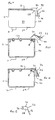
- Fig. 13 is a side elevation in cross-section of a cartridge in a third embodiment;
- Fig. 14 is the view of Fig. 13 with part of an element of the cartridge broken away;
- Fig. 15 is a fragmentary detail view of the break area of Fig. 14; and,
- Fig. 16 is an end elevation in cross-section at C-C of Fig. 14.
- The
cartridge 10 of the first embodiment is a generallyrectangular box 11 having atop 12. Thecartridge 10 includes threebreather holes 18 in thetop 12 which are equally spaced along a notional line parallel to and adjacent therear edge 14 of thecartridge 10. The top 12 further defines a plurality offill holes 16. - The
top 12 comprises a platelikemain body 20 and a plurality of dependinghollow bosses breather holes 18 and the plurality offill holes 16 respectively, thefill holes 16 being blocked byball bearings 28. Thebreather holes 18 are axially elongate. Thewalls 30 defining eachbreather hole 18 are tapered inwardly downwardly at an angle of about 1° to the axis of thebreather hole 18. Thecartridge 10 is made of plastics material. Thewalls 30 of thebreather holes 18 are polished. Thecartridge box 11 includes a hollow boss defining anoutlet port 31 depending from itsbottom surface 29. - An
element 32 comprises amain part 34 and three dependinghollow projections 36 which are received in thebreather holes 18. Theprojections 36 are of a complementary tapered shape to thebreather holes 18 and have polishedouter surfaces 38. Themain part 34 is generally rectangular and tray shaped and lies over the upper surface of thetop 12 extending rearwardly past therear edge 14 of thetop 12. Thefront edge 42 of themain part 34 terminates just past the forwardmost extent of theprojections 36. Themain part 34 is the same width as thetop 12. Tworibs 44 depend from themain part 34 and extend in the front to rear direction of thecartridge 10. Eachrib 44 terminates adjacent therear wall 46 of thebox 11. - A
printer 40 includeswalls cartridge receiving space 50. Extending upwardly into the bottom of thespace 50 is anink withdrawal needle 52 which is connected by a pipe (not shown) to a print head (not shown). - In use, the
element 32 blocks the breather holes 18 as themain part 34 blocks the ends of thehollow projections 36 which are firmly engaged in the breather holes 18. If thecartridge 10 is lowered into thecartridge receiving space 50, theribs 44 of theelement 32 of thecartridge 10 will foul on the top of therear wall 49 definingspace 50 preventing theoutlet port 31 of thecartridge 10 from receiving thewithdrawal needle 52. If thecartridge 10 is removed, the protrudingrear part 56 of themain part 34 can be grasped and lifted. As theprojections 36 are frictionally held, themain part 34 will be broken away with a snap action by the lever force applied. Theprojections 36 will be left in the breather holes 18 as shown in Fig. 8 and are now unblocked as the result of removal of themain part 34 so that there is a clear passageway through eachhollow projection 36 andbreather hole 18 into the interior of thecartridge 10. Thecartridge 10 can then be fitted in theprinter 40 with theink withdrawal needle 52 received in theoutlet port 31 of thecartridge 10. - The polished
outer surfaces 38 of theprojections 36 and thewalls 30 of the breather holes 18 and their tapered fit ensure that there is a strong frictional force holding theprojections 36 into the breather holes 18. - The
ribs 44 prevent themain part 34 being levered by the protrudingrear part 56 in the downwards direction as shown in the drawings which otherwise would use therear edge 14 of the top 12 as a fulcrum and the action would therefore tend to lever theprojections 36 out of the breather holes 18. Theribs 44 resist movement in that direction and therefore ensure that therear part 56 can only be moved in the opposite direction which is the correct direction to break the connection to theprojections 36. - The second embodiment is shown in Figs. 9 to 12. The second embodiment is similar to the first and only the differences from the first embodiment will be described. The same reference numerals will be used for equivalent features.
- In the second embodiment the
main part 34 is not tray-shaped and the protrudingrear part 56 extends downwardly from the remainder of themain part 34 at therear edge 14 of the top 12 of thecartridge box 11 at an angle of about 20° to therear wall 46 of thecartridge box 11. Theribs 44 extend over the length of therear part 56 and from therear part 56 to therear wall 46 of thebox 11 and are thus triangular. - The
element 32 further includes twoflanges 58 provided on opposite sides of themain part 34. Eachflange 58 depends from themain part 34 where it lies on the upper surface on the top 12 to closely lie adjacent aside surface 60 of thebox 11, and is also connected to the side edge of the protrudingpart 56. - In use, the
ribs 44 will prevent movement of themain part 34 in the direction towards therear wall 46 of thebox 11, as in the first embodiment. Theflanges 58 will also prevent movement of themain part 34 about a longitudinal axis in the plane of the top surface of the top 12 of thebox 11. Theelement 32 is thus confined to movement only about an axis parallel to therear edge 14 of thebox 11 and parallel to the line of breather holes 18. The fact that the protruding or extendedrear part 56 is at an angle reduces the risk of themain part 34 being broken off accidentally, while at the same time giving better leverage and an easier manual action when the user does want to break off themain part 34. It also spaces theoutlet port 31 of the cartridge further from thewithdrawal needle 52 of theprinter 40 on attempted entry of thecartridge 10 into theprinter 40. - The third embodiment shown in Figs 13 to 16 will now be described. The third embodiment is similar to the second embodiment and only the differences from the second embodiment will be described. The same reference numerals will be used for equivalent features.
- The top 12 of the
cartridge 10 has only the central one of the threebreather holes 18 of the other embodiments. The top 12 includes ashallow recess 70 in the upper surface 72 thereof around thebreather hole 18. Themain part 34 of theelement 32 includes a raisedland 74 on itsunderside 76 which is received in therecess 70. - A
longitudinal rib 78 depends from the underside of the top 12 to lie within thecartridge 10 and extends from therear wall 46 of thebox 11 nearly to the nearestfill hole boss 24. Therib 78 intersects theboss 22 defining thebreather hole 18 and there is a small gap in therib 78 around the end of thebreather hole 18 so that the passage of air through thebreather hole 18 is not obstructed by therib 78. Therib 78 is of substantially constant depth from therear wall 46 to past theboss 22 and then steadily decreases in depth. Aporous member 80 in the form of a sponge is provided in thebox 11 in use and is impregnated with ink. - In use, the
rib 78 keeps the ink impregnatedsponge 80 away from the end of thebreather hole 18 and this inhibits the entry of ink into thehollow projection 36 and thebreather hole 18. It was found that without therib 78 ink could be drawn into thehollow projection 36 and thebreather hole 18 by capillary action and that removal of themain part 34 could lead to ink "spitting" out of the top of thebreather hole 18. - If there should be any leakage of ink from the
breather hole 18 then therecess 70 confines the leakage so that the chances of a person handling thecartridge 10 getting ink on their fingers is reduced.
Claims (18)
- A cartridge for a printer, the cartridge including an element (32) for preventing the cartridge from being fully engaged in the printer, at least part (34) of the element (32) being arranged to be removed to enable the cartridge to be fully engaged in a printer and to open at least one aperture into the cartridge, the element (32) including at least one projection (36), the or each projection (36) being received in an aperture (18) of the cartridge to connect the element (32) to the cartridge, characterised in that a hole is provided which extends into the or each projection (36) and terminates in a blind end in the removable part (34) so that when the removable part (34) has been removed, the hole provides a passageway into the cartridge.
- A cartridge as claimed in claim 1, wherein the element (32) is rigid.
- A cartridge as claimed in claim 1 or claim 2, wherein the element (32) is protruding.
- A cartridge as claimed in claim 1, 2 or 3, wherein the element (32) is arranged to be removed by being broken off.
- A cartridge as claimed in any preceding claim, wherein the element (32) is arranged to be removed by being snapped off.
- A cartridge as claimed in any preceding claim, wherein the aperture (18) is a breather hole (18).
- A cartridge as claimed in any preceding claim, wherein the or each projection (36) and the or each aperture (18) have complementary surfaces (30, 38), which are preferably polished.
- A cartridge as claimed in claim 7, wherein the or each projection (36) and the or each aperture (18) are tapered.
- A cartridge as claimed in claim 8, wherein the taper is less than 5 °, preferably about 1°.
- A cartridge as claimed in any preceding claim, wherein at least part of the removable part (34) of the element (32) extends substantially perpendicularly to the axis of the or each projection (36).
- A cartridge as claimed in any preceding claim, wherein the surface in which the or each aperture (18) is formed defines a recess (70) around the or each aperture (18) and at least part (74) of the removable part (34) lies in the recess (70).
- A cartridge as claimed in any preceding claim, wherein at least a portion of the removable part (34) of the element (32) lies adjacent a surface of the cartridge.
- A cartridge as claimed in claim 12, wherein at least a portion of the removable part (34) of the element (32) lies adjacent the surface (12) in which the or each aperture (18) is formed.
- A cartridge as claimed in any preceding claim, wherein the removable part (34) includes a protruding part (56) which extends beyond the surface (12) in which the or each aperture (18) is formed and which preferably extends downwardly at an angle.
- A cartridge as claimed in claim 12, 13 or 14, wherein the removable part (34) includes a portion (58) which lies adjacent a second surface (60) of the cartridge, the second surface (60) preferably being perpendicular to the first surface (12).
- A cartridge as claimed in claim 15, wherein the removable part (34) includes a portion (58, 44) which lies adjacent a third surface (60, 46) of the cartridge, the third surface (60, 46) preferably being perpendicular to the first and/or second surfaces (12, 60).
- A cartridge as claimed in claim 16, wherein the removable part (34) further includes a portion (58, 44) which lies adjacent a fourth surface (60, 46) of the cartridge, the fourth surface (60, 46) preferably being parallel to one of the other surfaces (12, 60).
- The combination comprising:- a cartridge as claimed in any preceding claim; and,- a printer.
Applications Claiming Priority (4)
| Application Number | Priority Date | Filing Date | Title |
|---|---|---|---|
| GB9901995 | 1999-01-30 | ||
| GBGB9901995.2A GB9901995D0 (en) | 1999-01-30 | 1999-01-30 | A cartridge and the combination of a cartridge and a printer |
| GB9904498 | 1999-03-01 | ||
| GBGB9904498.4A GB9904498D0 (en) | 1999-01-30 | 1999-03-01 | A cartridge and the combination of a cartridge and a printer |
Publications (3)
| Publication Number | Publication Date |
|---|---|
| EP1024009A2 EP1024009A2 (en) | 2000-08-02 |
| EP1024009A3 EP1024009A3 (en) | 2000-09-20 |
| EP1024009B1 true EP1024009B1 (en) | 2007-04-04 |
Family
ID=26315059
Family Applications (1)
| Application Number | Title | Priority Date | Filing Date |
|---|---|---|---|
| EP00300661A Expired - Lifetime EP1024009B1 (en) | 1999-01-30 | 2000-01-28 | A cartridge and the combination of a cartridge and a printer |
Country Status (7)
| Country | Link |
|---|---|
| US (1) | US6412930B1 (en) |
| EP (1) | EP1024009B1 (en) |
| AT (1) | ATE358586T1 (en) |
| AU (1) | AU761941B2 (en) |
| DE (1) | DE60034165T2 (en) |
| ES (1) | ES2283272T3 (en) |
| GB (1) | GB2350323B (en) |
Families Citing this family (5)
| Publication number | Priority date | Publication date | Assignee | Title |
|---|---|---|---|---|
| US6474802B1 (en) * | 2001-12-14 | 2002-11-05 | Monitek Electronics Limited | Ink cartridge |
| KR100421972B1 (en) | 2002-05-16 | 2004-03-11 | 삼성전자주식회사 | Ink cartridge |
| GB0402655D0 (en) | 2004-02-06 | 2004-03-10 | Dynamic Cassette Int | An ink container |
| US7325912B2 (en) * | 2004-10-06 | 2008-02-05 | Hewlett-Packard Development Company, L.P. | Breachable seal |
| JP2018176653A (en) * | 2017-04-20 | 2018-11-15 | セイコーエプソン株式会社 | Liquid container and liquid injection device |
Family Cites Families (14)
| Publication number | Priority date | Publication date | Assignee | Title |
|---|---|---|---|---|
| JP3513979B2 (en) * | 1994-09-16 | 2004-03-31 | セイコーエプソン株式会社 | Ink cartridge for inkjet printer |
| JP3066867B2 (en) * | 1988-10-31 | 2000-07-17 | キヤノン株式会社 | Inkjet printer, recording head, ink cassette and sales set for inkjet recording |
| US5329294A (en) * | 1992-09-24 | 1994-07-12 | Repeat-O-Type Mfg. Co., Inc. | User refillable ink jet cartridge and method for making said cartridge |
| JP2839997B2 (en) * | 1992-12-09 | 1998-12-24 | 株式会社リコー | Recording head unit |
| US5392063A (en) * | 1993-04-30 | 1995-02-21 | Hewlett-Packard Company | Spring cartridge clamp for inkjet printer carriage |
| JP3188056B2 (en) * | 1993-07-21 | 2001-07-16 | キヤノン株式会社 | Ink jet recording device and ink jet head |
| US5515663A (en) * | 1994-04-06 | 1996-05-14 | Nu-Kote International, Inc. | Method of refilling ink-jet printer cartridges |
| EP0685340B1 (en) * | 1994-05-31 | 1999-08-18 | Canon Kabushiki Kaisha | Replaceable ink cartridge and seal structure thereof |
| JPH08230205A (en) * | 1995-02-28 | 1996-09-10 | Canon Inc | Ink tank protection method and member, and ink tank having the same |
| JP3327807B2 (en) * | 1996-03-01 | 2002-09-24 | キヤノン株式会社 | Ink tank packaging structure and ink tank provided with the packaging structure |
| US5847735A (en) * | 1996-04-26 | 1998-12-08 | Pelikan Produktions Ag | Ink cartridge for a printer |
| JP3612885B2 (en) * | 1996-08-28 | 2005-01-19 | セイコーエプソン株式会社 | Ink cartridge and printer |
| JP3295366B2 (en) * | 1997-02-19 | 2002-06-24 | キヤノン株式会社 | Liquid holding container with cap, cap and liquid holding container |
| US6283587B1 (en) * | 1998-03-20 | 2001-09-04 | Seiko Epson Corporation | Printer ink cartridge and ink cartridge device including the same |
-
2000
- 2000-01-28 EP EP00300661A patent/EP1024009B1/en not_active Expired - Lifetime
- 2000-01-28 AT AT00300661T patent/ATE358586T1/en not_active IP Right Cessation
- 2000-01-28 ES ES00300661T patent/ES2283272T3/en not_active Expired - Lifetime
- 2000-01-28 AU AU13620/00A patent/AU761941B2/en not_active Ceased
- 2000-01-28 GB GB0002108A patent/GB2350323B/en not_active Expired - Fee Related
- 2000-01-28 DE DE60034165T patent/DE60034165T2/en not_active Expired - Lifetime
- 2000-01-31 US US09/495,435 patent/US6412930B1/en not_active Expired - Fee Related
Also Published As
| Publication number | Publication date |
|---|---|
| AU761941B2 (en) | 2003-06-12 |
| US6412930B1 (en) | 2002-07-02 |
| DE60034165T2 (en) | 2008-01-03 |
| DE60034165D1 (en) | 2007-05-16 |
| GB2350323B (en) | 2002-12-11 |
| ES2283272T3 (en) | 2007-11-01 |
| GB0002108D0 (en) | 2000-03-22 |
| ATE358586T1 (en) | 2007-04-15 |
| EP1024009A3 (en) | 2000-09-20 |
| GB2350323A (en) | 2000-11-29 |
| EP1024009A2 (en) | 2000-08-02 |
| AU1362000A (en) | 2000-08-03 |
Similar Documents
| Publication | Publication Date | Title |
|---|---|---|
| EP1359019B1 (en) | Feed channel keying for solid ink stick feed | |
| EP1044815B1 (en) | Liquid container, recording head and recording apparatus using same | |
| EP1527882B1 (en) | Ink cartridge for ink-jet printing apparatus | |
| EP0773109B1 (en) | Ink refilling method and apparatus, ink container refilled therewith and ink jet apparatus comprising ink refilling apparatus | |
| EP0655336B1 (en) | Improved ink container, installing-removing method therefor, and apparatus usable with the same | |
| EP1247650B1 (en) | Ink cartridge and ink-jet recording apparatus | |
| US7934794B2 (en) | Ink cartridge | |
| DK2527153T5 (en) | Combined ink family profiling to an ink cartridge | |
| US6145972A (en) | Container for liquid to be ejected | |
| EP0728586B1 (en) | Ink supply unit and recorder | |
| US6761444B2 (en) | Channel keying for solid ink stick insertion | |
| JP2621923B2 (en) | Vents and ink cartridges | |
| EP0666176A2 (en) | Connector assembly for ink cartridge | |
| KR20010013262A (en) | Method and apparatus for securing an ink container | |
| EP1024009B1 (en) | A cartridge and the combination of a cartridge and a printer | |
| JP3363052B2 (en) | Ink supply device and ink filling method | |
| EP0727314B1 (en) | Ink supply unit | |
| EP1447225A1 (en) | Key plate assembly | |
| HK1029967A (en) | A cartridge and the combination of a cartridge and a printer | |
| JP2007268792A (en) | ink cartridge | |
| KR0126866Y1 (en) | Head storage container of ink jet printer | |
| US6062683A (en) | Container for safekeeping ink cartridge | |
| EP1086816A2 (en) | An ink cartridge | |
| US5949457A (en) | Connecting structure for a head holder and ink cartridge | |
| PT1024009E (en) | A cartridge and the combination of a cartridge and a printer |
Legal Events
| Date | Code | Title | Description |
|---|---|---|---|
| PUAI | Public reference made under article 153(3) epc to a published international application that has entered the european phase |
Free format text: ORIGINAL CODE: 0009012 |
|
| AK | Designated contracting states |
Kind code of ref document: A2 Designated state(s): AT BE CH CY DE DK ES FI FR GB GR IE IT LI LU MC NL PT SE |
|
| AX | Request for extension of the european patent |
Free format text: AL;LT;LV;MK;RO;SI |
|
| PUAL | Search report despatched |
Free format text: ORIGINAL CODE: 0009013 |
|
| AK | Designated contracting states |
Kind code of ref document: A3 Designated state(s): AT BE CH CY DE DK ES FI FR GB GR IE IT LI LU MC NL PT SE |
|
| AX | Request for extension of the european patent |
Free format text: AL;LT;LV;MK;RO;SI |
|
| 17P | Request for examination filed |
Effective date: 20010309 |
|
| AKX | Designation fees paid |
Free format text: AT BE CH CY DE DK ES FI FR GB GR IE IT LI LU MC NL PT SE |
|
| 17Q | First examination report despatched |
Effective date: 20050309 |
|
| GRAP | Despatch of communication of intention to grant a patent |
Free format text: ORIGINAL CODE: EPIDOSNIGR1 |
|
| GRAS | Grant fee paid |
Free format text: ORIGINAL CODE: EPIDOSNIGR3 |
|
| RBV | Designated contracting states (corrected) |
Designated state(s): AT BE CH CY DE DK ES FI FR GR IE IT LI LU MC NL PT SE |
|
| GRAA | (expected) grant |
Free format text: ORIGINAL CODE: 0009210 |
|
| AK | Designated contracting states |
Kind code of ref document: B1 Designated state(s): AT BE CH CY DE DK ES FI FR GR IE IT LI LU MC NL PT SE |
|
| PG25 | Lapsed in a contracting state [announced via postgrant information from national office to epo] |
Ref country code: CH Free format text: LAPSE BECAUSE OF FAILURE TO SUBMIT A TRANSLATION OF THE DESCRIPTION OR TO PAY THE FEE WITHIN THE PRESCRIBED TIME-LIMIT Effective date: 20070404 Ref country code: LI Free format text: LAPSE BECAUSE OF FAILURE TO SUBMIT A TRANSLATION OF THE DESCRIPTION OR TO PAY THE FEE WITHIN THE PRESCRIBED TIME-LIMIT Effective date: 20070404 Ref country code: FI Free format text: LAPSE BECAUSE OF FAILURE TO SUBMIT A TRANSLATION OF THE DESCRIPTION OR TO PAY THE FEE WITHIN THE PRESCRIBED TIME-LIMIT Effective date: 20070404 |
|
| REG | Reference to a national code |
Ref country code: CH Ref legal event code: EP |
|
| REF | Corresponds to: |
Ref document number: 60034165 Country of ref document: DE Date of ref document: 20070516 Kind code of ref document: P |
|
| REG | Reference to a national code |
Ref country code: IE Ref legal event code: FG4D |
|
| REG | Reference to a national code |
Ref country code: PT Ref legal event code: SC4A Free format text: AVAILABILITY OF NATIONAL TRANSLATION Effective date: 20070622 |
|
| PG25 | Lapsed in a contracting state [announced via postgrant information from national office to epo] |
Ref country code: SE Free format text: LAPSE BECAUSE OF FAILURE TO SUBMIT A TRANSLATION OF THE DESCRIPTION OR TO PAY THE FEE WITHIN THE PRESCRIBED TIME-LIMIT Effective date: 20070704 |
|
| REG | Reference to a national code |
Ref country code: HK Ref legal event code: WD Ref document number: 1029967 Country of ref document: HK |
|
| ET | Fr: translation filed | ||
| REG | Reference to a national code |
Ref country code: CH Ref legal event code: PL |
|
| REG | Reference to a national code |
Ref country code: ES Ref legal event code: FG2A Ref document number: 2283272 Country of ref document: ES Kind code of ref document: T3 |
|
| PG25 | Lapsed in a contracting state [announced via postgrant information from national office to epo] |
Ref country code: AT Free format text: LAPSE BECAUSE OF FAILURE TO SUBMIT A TRANSLATION OF THE DESCRIPTION OR TO PAY THE FEE WITHIN THE PRESCRIBED TIME-LIMIT Effective date: 20070404 |
|
| PG25 | Lapsed in a contracting state [announced via postgrant information from national office to epo] |
Ref country code: BE Free format text: LAPSE BECAUSE OF FAILURE TO SUBMIT A TRANSLATION OF THE DESCRIPTION OR TO PAY THE FEE WITHIN THE PRESCRIBED TIME-LIMIT Effective date: 20070404 |
|
| PG25 | Lapsed in a contracting state [announced via postgrant information from national office to epo] |
Ref country code: DK Free format text: LAPSE BECAUSE OF FAILURE TO SUBMIT A TRANSLATION OF THE DESCRIPTION OR TO PAY THE FEE WITHIN THE PRESCRIBED TIME-LIMIT Effective date: 20070404 |
|
| PLBE | No opposition filed within time limit |
Free format text: ORIGINAL CODE: 0009261 |
|
| STAA | Information on the status of an ep patent application or granted ep patent |
Free format text: STATUS: NO OPPOSITION FILED WITHIN TIME LIMIT |
|
| 26N | No opposition filed |
Effective date: 20080107 |
|
| PG25 | Lapsed in a contracting state [announced via postgrant information from national office to epo] |
Ref country code: GR Free format text: LAPSE BECAUSE OF FAILURE TO SUBMIT A TRANSLATION OF THE DESCRIPTION OR TO PAY THE FEE WITHIN THE PRESCRIBED TIME-LIMIT Effective date: 20070705 Ref country code: IT Free format text: LAPSE BECAUSE OF FAILURE TO SUBMIT A TRANSLATION OF THE DESCRIPTION OR TO PAY THE FEE WITHIN THE PRESCRIBED TIME-LIMIT Effective date: 20070404 |
|
| PG25 | Lapsed in a contracting state [announced via postgrant information from national office to epo] |
Ref country code: MC Free format text: LAPSE BECAUSE OF NON-PAYMENT OF DUE FEES Effective date: 20080131 |
|
| PG25 | Lapsed in a contracting state [announced via postgrant information from national office to epo] |
Ref country code: IE Free format text: LAPSE BECAUSE OF NON-PAYMENT OF DUE FEES Effective date: 20080128 |
|
| PG25 | Lapsed in a contracting state [announced via postgrant information from national office to epo] |
Ref country code: CY Free format text: LAPSE BECAUSE OF FAILURE TO SUBMIT A TRANSLATION OF THE DESCRIPTION OR TO PAY THE FEE WITHIN THE PRESCRIBED TIME-LIMIT Effective date: 20070404 |
|
| PG25 | Lapsed in a contracting state [announced via postgrant information from national office to epo] |
Ref country code: LU Free format text: LAPSE BECAUSE OF NON-PAYMENT OF DUE FEES Effective date: 20080128 |
|
| PGFP | Annual fee paid to national office [announced via postgrant information from national office to epo] |
Ref country code: ES Payment date: 20121231 Year of fee payment: 14 Ref country code: FR Payment date: 20130225 Year of fee payment: 14 Ref country code: DE Payment date: 20130122 Year of fee payment: 14 |
|
| PGFP | Annual fee paid to national office [announced via postgrant information from national office to epo] |
Ref country code: NL Payment date: 20130130 Year of fee payment: 14 |
|
| PGFP | Annual fee paid to national office [announced via postgrant information from national office to epo] |
Ref country code: PT Payment date: 20130116 Year of fee payment: 14 |
|
| REG | Reference to a national code |
Ref country code: DE Ref legal event code: R119 Ref document number: 60034165 Country of ref document: DE |
|
| REG | Reference to a national code |
Ref country code: PT Ref legal event code: MM4A Free format text: LAPSE DUE TO NON-PAYMENT OF FEES Effective date: 20140728 |
|
| REG | Reference to a national code |
Ref country code: NL Ref legal event code: V1 Effective date: 20140801 |
|
| PG25 | Lapsed in a contracting state [announced via postgrant information from national office to epo] |
Ref country code: DE Free format text: LAPSE BECAUSE OF NON-PAYMENT OF DUE FEES Effective date: 20140801 Ref country code: NL Free format text: LAPSE BECAUSE OF NON-PAYMENT OF DUE FEES Effective date: 20140801 |
|
| REG | Reference to a national code |
Ref country code: FR Ref legal event code: ST Effective date: 20140930 |
|
| REG | Reference to a national code |
Ref country code: DE Ref legal event code: R119 Ref document number: 60034165 Country of ref document: DE Effective date: 20140801 |
|
| PG25 | Lapsed in a contracting state [announced via postgrant information from national office to epo] |
Ref country code: FR Free format text: LAPSE BECAUSE OF NON-PAYMENT OF DUE FEES Effective date: 20140131 |
|
| PG25 | Lapsed in a contracting state [announced via postgrant information from national office to epo] |
Ref country code: PT Free format text: LAPSE BECAUSE OF NON-PAYMENT OF DUE FEES Effective date: 20140728 |
|
| REG | Reference to a national code |
Ref country code: ES Ref legal event code: FD2A Effective date: 20150331 |
|
| PG25 | Lapsed in a contracting state [announced via postgrant information from national office to epo] |
Ref country code: ES Free format text: LAPSE BECAUSE OF NON-PAYMENT OF DUE FEES Effective date: 20140129 |