EP0265380A2 - Manual apparatus with a removable tool holder - Google Patents
Manual apparatus with a removable tool holder Download PDFInfo
- Publication number
- EP0265380A2 EP0265380A2 EP87810578A EP87810578A EP0265380A2 EP 0265380 A2 EP0265380 A2 EP 0265380A2 EP 87810578 A EP87810578 A EP 87810578A EP 87810578 A EP87810578 A EP 87810578A EP 0265380 A2 EP0265380 A2 EP 0265380A2
- Authority
- EP
- European Patent Office
- Prior art keywords
- spring
- hand tool
- chuck body
- tool holder
- tool according
- Prior art date
- Legal status (The legal status is an assumption and is not a legal conclusion. Google has not performed a legal analysis and makes no representation as to the accuracy of the status listed.)
- Granted
Links
Images

Classifications
-
- B—PERFORMING OPERATIONS; TRANSPORTING
- B23—MACHINE TOOLS; METAL-WORKING NOT OTHERWISE PROVIDED FOR
- B23Q—DETAILS, COMPONENTS, OR ACCESSORIES FOR MACHINE TOOLS, e.g. ARRANGEMENTS FOR COPYING OR CONTROLLING; MACHINE TOOLS IN GENERAL CHARACTERISED BY THE CONSTRUCTION OF PARTICULAR DETAILS OR COMPONENTS; COMBINATIONS OR ASSOCIATIONS OF METAL-WORKING MACHINES, NOT DIRECTED TO A PARTICULAR RESULT
- B23Q3/00—Devices holding, supporting, or positioning work or tools, of a kind normally removable from the machine
- B23Q3/12—Devices holding, supporting, or positioning work or tools, of a kind normally removable from the machine for securing to a spindle in general
-
- B—PERFORMING OPERATIONS; TRANSPORTING
- B23—MACHINE TOOLS; METAL-WORKING NOT OTHERWISE PROVIDED FOR
- B23B—TURNING; BORING
- B23B31/00—Chucks; Expansion mandrels; Adaptations thereof for remote control
- B23B31/008—Chucks; Expansion mandrels; Adaptations thereof for remote control with arrangements for transmitting torque
-
- B—PERFORMING OPERATIONS; TRANSPORTING
- B23—MACHINE TOOLS; METAL-WORKING NOT OTHERWISE PROVIDED FOR
- B23B—TURNING; BORING
- B23B31/00—Chucks; Expansion mandrels; Adaptations thereof for remote control
- B23B31/02—Chucks
- B23B31/10—Chucks characterised by the retaining or gripping devices or their immediate operating means
- B23B31/107—Retention by laterally-acting detents, e.g. pins, screws, wedges; Retention by loose elements, e.g. balls
- B23B31/1071—Retention by balls
-
- B—PERFORMING OPERATIONS; TRANSPORTING
- B25—HAND TOOLS; PORTABLE POWER-DRIVEN TOOLS; MANIPULATORS
- B25D—PERCUSSIVE TOOLS
- B25D17/00—Details of, or accessories for, portable power-driven percussive tools
- B25D17/08—Means for retaining and guiding the tool bit, e.g. chucks allowing axial oscillation of the tool bit
- B25D17/084—Rotating chucks or sockets
- B25D17/088—Rotating chucks or sockets with radial movable locking elements co-operating with bit shafts specially adapted therefor
-
- B—PERFORMING OPERATIONS; TRANSPORTING
- B25—HAND TOOLS; PORTABLE POWER-DRIVEN TOOLS; MANIPULATORS
- B25D—PERCUSSIVE TOOLS
- B25D2217/00—Details of, or accessories for, portable power-driven percussive tools
- B25D2217/003—Details relating to chucks with radially movable locking elements
- B25D2217/0038—Locking members of special shape
- B25D2217/0042—Ball-shaped locking members
-
- B—PERFORMING OPERATIONS; TRANSPORTING
- B25—HAND TOOLS; PORTABLE POWER-DRIVEN TOOLS; MANIPULATORS
- B25D—PERCUSSIVE TOOLS
- B25D2217/00—Details of, or accessories for, portable power-driven percussive tools
- B25D2217/003—Details relating to chucks with radially movable locking elements
- B25D2217/0038—Locking members of special shape
- B25D2217/0049—Roll-shaped locking members
-
- B—PERFORMING OPERATIONS; TRANSPORTING
- B25—HAND TOOLS; PORTABLE POWER-DRIVEN TOOLS; MANIPULATORS
- B25D—PERCUSSIVE TOOLS
- B25D2217/00—Details of, or accessories for, portable power-driven percussive tools
- B25D2217/003—Details relating to chucks with radially movable locking elements
- B25D2217/0053—Devices for securing the tool retainer to the machine part
-
- Y—GENERAL TAGGING OF NEW TECHNOLOGICAL DEVELOPMENTS; GENERAL TAGGING OF CROSS-SECTIONAL TECHNOLOGIES SPANNING OVER SEVERAL SECTIONS OF THE IPC; TECHNICAL SUBJECTS COVERED BY FORMER USPC CROSS-REFERENCE ART COLLECTIONS [XRACs] AND DIGESTS
- Y10—TECHNICAL SUBJECTS COVERED BY FORMER USPC
- Y10S—TECHNICAL SUBJECTS COVERED BY FORMER USPC CROSS-REFERENCE ART COLLECTIONS [XRACs] AND DIGESTS
- Y10S279/00—Chucks or sockets
- Y10S279/904—Quick change socket
- Y10S279/905—Quick change socket with ball detent
-
- Y—GENERAL TAGGING OF NEW TECHNOLOGICAL DEVELOPMENTS; GENERAL TAGGING OF CROSS-SECTIONAL TECHNOLOGIES SPANNING OVER SEVERAL SECTIONS OF THE IPC; TECHNICAL SUBJECTS COVERED BY FORMER USPC CROSS-REFERENCE ART COLLECTIONS [XRACs] AND DIGESTS
- Y10—TECHNICAL SUBJECTS COVERED BY FORMER USPC
- Y10T—TECHNICAL SUBJECTS COVERED BY FORMER US CLASSIFICATION
- Y10T279/00—Chucks or sockets
- Y10T279/17—Socket type
- Y10T279/17042—Lost motion
- Y10T279/17068—Rotary socket
-
- Y—GENERAL TAGGING OF NEW TECHNOLOGICAL DEVELOPMENTS; GENERAL TAGGING OF CROSS-SECTIONAL TECHNOLOGIES SPANNING OVER SEVERAL SECTIONS OF THE IPC; TECHNICAL SUBJECTS COVERED BY FORMER USPC CROSS-REFERENCE ART COLLECTIONS [XRACs] AND DIGESTS
- Y10—TECHNICAL SUBJECTS COVERED BY FORMER USPC
- Y10T—TECHNICAL SUBJECTS COVERED BY FORMER US CLASSIFICATION
- Y10T279/00—Chucks or sockets
- Y10T279/17—Socket type
- Y10T279/17615—Obliquely guided reciprocating jaws
- Y10T279/17623—Threaded sleeve and jaw
- Y10T279/17632—Conical sleeve
-
- Y—GENERAL TAGGING OF NEW TECHNOLOGICAL DEVELOPMENTS; GENERAL TAGGING OF CROSS-SECTIONAL TECHNOLOGIES SPANNING OVER SEVERAL SECTIONS OF THE IPC; TECHNICAL SUBJECTS COVERED BY FORMER USPC CROSS-REFERENCE ART COLLECTIONS [XRACs] AND DIGESTS
- Y10—TECHNICAL SUBJECTS COVERED BY FORMER USPC
- Y10T—TECHNICAL SUBJECTS COVERED BY FORMER US CLASSIFICATION
- Y10T279/00—Chucks or sockets
- Y10T279/17—Socket type
- Y10T279/17666—Radially reciprocating jaws
- Y10T279/17692—Moving-cam actuator
- Y10T279/17717—Rotary eccentric-cam sleeve
- Y10T279/17726—Roller and rocking jaw
-
- Y—GENERAL TAGGING OF NEW TECHNOLOGICAL DEVELOPMENTS; GENERAL TAGGING OF CROSS-SECTIONAL TECHNOLOGIES SPANNING OVER SEVERAL SECTIONS OF THE IPC; TECHNICAL SUBJECTS COVERED BY FORMER USPC CROSS-REFERENCE ART COLLECTIONS [XRACs] AND DIGESTS
- Y10—TECHNICAL SUBJECTS COVERED BY FORMER USPC
- Y10T—TECHNICAL SUBJECTS COVERED BY FORMER US CLASSIFICATION
- Y10T408/00—Cutting by use of rotating axially moving tool
- Y10T408/94—Tool-support
- Y10T408/95—Tool-support with tool-retaining means
- Y10T408/953—Clamping jaws
Definitions
- the invention relates to a hand-held device, such as a drill, hammer drill, screwdriver and the like, with a detachable tool holder arranged on a rotating spindle of the device for holding tools, the tool holder having a chuck body which engages with the rotating spindle and partially overlaps the rotating spindle with a sleeve-shaped region and the chuck body is rotationally connected to the rotating spindle.
- the entire tool holder could not prevail, since no solutions are known that allow replacement without a lot of time and tools.
- the tool holder known from DE-OS 33 10 371 can only be detached from the rotating spindle of the hand-held device with a special amount of tools.
- a set screw must be loosened using a tool and then an adjusting ring in one certain position are offset so that clamping elements release the connection between the chuck body and the rotating spindle.
- the type of connection between the tool holder and the rotating spindle known from this publication requires a relatively long guide area for guiding the tool holder on the rotating spindle, so that a sufficient concentricity and axial runout is ensured.
- the invention has for its object to provide a handheld device, the tool holder is interchangeable without auxiliary tools, the connection between the tool holder and rotating spindle ensures concentricity and axial runout and allows short overall length.
- the overall length can be kept short, since only the length of the tapered support surfaces is relevant.
- their cone angle is outside the self-locking and is expediently 25 to 35 °.
- the tapered support surfaces are formed by a taper and a taper opening, the taper preferably located on the rotating spindle and the taper opening on the chuck body.
- the play-free engagement of the tapered pin in the tapered opening is preferably served by a plurality of clamping elements which are evenly distributed in the circumferential direction of the tool holder and guided in through-openings of the chuck body and are pressed by the spring against the inclined flank of the recess adjacent to the free end of the rotating spindle.
- the spring is tensioned from the outside using an operating handle.
- the Flank expediently extends from the lateral surface of the rotating spindle to the base of the recesses at an angle of approximately 45 ° to the rotating spindle axis.
- the clamping elements have the function of axially holding the tool holder on the rotating spindle; the transmission of any rotary movement is expediently carried out by separate, preferably form-fitting transmission means, such as, for example, splines.
- the recess for engaging the clamping elements is advantageously designed as a circumferential annular groove.
- An annular groove is easy to manufacture and simplifies the connection of the tool holder to the rotating spindle, since the tool holder can be attached in any rotational position, since the clamping elements can always move into the annular groove regardless of the rotational position.
- the clamping elements are designed as balls. Balls are not only inexpensive mass-produced items but also an element that is characterized by simple assembly and function due to its shape.
- the spring acts on the clamping elements as radially as possible in order to use the entire force of the spring without losses due to deflection to engage the clamping elements. This also prevents pinching effects.
- the spring is designed as an annular spring acting on the tensioning elements, the inner side of which rests under prestress on the sleeve-shaped area of the chuck body and engages the tensioning elements in the annular groove.
- the annular spring is advantageously designed to be polygonal in the axial projection, the number of corners being able to correspond to the number of clamping elements.
- the clamping elements face the side surfaces or the corners of the inside of the ring spring.
- the side surfaces of the ring spring lie curved under prestress on the outer surface of the sleeve-shaped region of the chuck body. As a result, the clamping elements are pushed into the recesses from the side surfaces with a corresponding rotational position.
- the spring for acting on the tensioning elements is designed as a plate spring assembly.
- a handle sleeve that is rotatable relative to the chuck body is preferably suitable as an actuating handle for the spring.
- the ring spring can be fixed axially on one side and in a rotationally locking manner.
- the axially free-standing section of the ring spring serves to act on the clamping elements.
- the inside of the grip sleeve has a control contour with the number of clamping elements and a corresponding number of escape niches for the plate spring assembly.
- the control contour causes tensioning of the plate spring assembly and thus the engagement of the tensioning elements in the recesses, which leads to the desired play-free Ver clamping of the tapered support surfaces of the chuck body and rotating spindle leads.
- the escape niches get into the radial projection of the clamping elements, which relaxes the spring assemblies and consequently allows the clamping elements to disengage to change the tool holder.
- Locking means can be provided to lock the grip sleeve in its functional positions.
- These latching means can be, for example, balls which are acted upon by spring force and which are mounted radially displaceably in the grip sleeve and can be inserted into latching openings on the chuck body. Furthermore, the turning of the gripping sleeve from the one blocking position into the other functional position can also be provided.
- the handheld device shown in FIG. 1 has a housing 1 with a laterally protruding handle 2.
- a push-button 3 is used to switch the hand-held device on and off.
- a tool holder, generally designated 4 is detachably connected to a rotating spindle, generally designated 5.
- the tool holder 4 shown enlarged in FIG. 2 has a chuck body designated overall by 6, an adjusting sleeve 7 for clamping jaws 8 and a handle sleeve designated overall by 9, in which an annular spring 11 is fixed axially on one side.
- the chuck body 6 has a sleeve-shaped region 12 with a conical opening 13 facing the rotating spindle 5.
- a stepped cylindrical base bore 14 adjoins the cone opening 13.
- the sleeve-shaped region 12 is provided with three through openings 15 which, as can be seen in FIG. 3, are evenly distributed in the circumferential direction of the chuck body 6.
- a ball 16 is seated in each passage opening 15. The balls 16 are supported radially outward on the free-standing section of the ring spring 11.
- the chuck body 6 also has latching recesses 17 on the outside for engaging a spherical latching body 18 for the purpose of fixing the grip sleeve 9 in a respective function-related rotational position relative to the chuck body 6.
- the latching body 18 is radially displaceably mounted in a recess 19 in the grip sleeve 9 and acted upon by a compression spring 21 .
- the rotary spindle 5 is penetrated by a central bore 22, in which, as can be seen in FIG. 3, an implicitly recognizable impact transmission striker 23 is guided.
- a spline toothing 24 is provided on the rotating spindle 5, which is in engagement with an opposing spline toothing 25 on the chuck body 6.
- the free end section 26 of the rotary spindle 5 is designed as a taper pin 27, the taper angle of which corresponds to the taper angle of the taper opening 13. In the widening direction, the taper pin 27 is delimited by a circumferential annular groove 28.
- the axial extent of the annular groove 28 shortens towards the bottom thereof, this shortening being achieved by a corresponding inclination of a flank 29 facing the free end of the tapered pin 27.
- the annular spring 11 is designed to be polygonal in the axial projection.
- the balls 16 can thus escape from the ring groove to the corners 32, as shown in FIGS. 4 and 5.
- FIG. 6 to 8 show a tool holder, generally designated 41 for turning operation. This in turn sits on a rotary spindle, generally designated 42.
- the tool holder 41 has a chuck body, generally designated 43, on which a handle sleeve, generally designated 44, is rotatably mounted.
- the chuck body 43 is penetrated by a cylindrical longitudinal bore 45, to which a conical opening 46 adjoins the rotary spindle 42 for engagement of the rotary spindle 42.
- the rotary spindle 42 has a corresponding taper pin 47 for play-free centric engagement.
- the rotary spindle 42 is penetrated by an impact transfer striker 48 which on the one hand conveys the rotary movement to the rotary spindle 42 and on the other hand gives 49 impulses to a tool guided in the longitudinal bore 45.
- the rotary transmission striker 48 which carries out the rotation, has driving grooves 51 into which roller-shaped locking elements 52, which are mounted in openings 53 in the rotary spindle 42, engage in order to transmit the rotary movement.
- the locking elements 52 are held in the engaged position by a support ring 54.
- the section of the rotary spindle 42 engaging in the chuck body 43 is provided with a circumferential annular groove 55, the axial extent of which is shortened toward the bottom.
- the inclination of the flank 56 of the annular groove 55 adjacent to the free end of the rotating spindle contributes to this shortening.
- trough-shaped depressions 57 which are diametrically opposite one another are introduced into the lateral surface of the rotary spindle 42.
- the sleeve-shaped region 58 of the chuck body 43 which receives part of the rotary spindle 42 is provided with radially extending passage openings 59 in the free end region.
- a ball 61 is slidably mounted and is normally acted upon by a plate spring assembly 62 toward the tool holder axis.
- the plate spring assembly 62 is supported by a slide shoe 63 toward the inside 64 of the grip sleeve 44. In the functional position shown, the disk spring assembly 62 is tensioned and presses the ball 61 against the flank 56. This results in the taper pin 47 being clamped in the taper opening 46 without play.
- roller-shaped locking elements 65 engage in the recesses 57 on the rotary spindle 42 and are mounted so as to be radially displaceable in openings 66 in the chuck body.
- the locking elements 65 are supported radially outward on the grip sleeve 44.
- Circlips 67, 68 prevent the axial displacement of the grip sleeve 44 and the support ring 54.
- a stop ring 69 is screwed onto the chuck body 43 in the free end region.
- An elastic ring 71 is used to seal the tool 49.
- An infeed collar 72 is slidably mounted on the chuck body 43.
- a cylinder spring 73 drives the feed collar 72 into the run-up position shown against the stop ring 69.
- a further elastic ring 74 dampens the impact of the feed collar 72.
- roller-shaped locking elements 76 are in turn radially displaceably mounted. These are inserted into the tool-side drive grooves 77 for holding and driving the tool 49.
- an infeed contour 78 provided on the inside of the infeed collar 72 is used.
- the infeed collar 72 is displaced against the force of the cylinder spring 73 towards the rotary spindle 42, as a result of which recesses in the infeed contour 78 reach the locking elements 76 in radial projection and disengage Allow locking elements 76.
- FIG. 7 and 8 illustrate the interaction of the grip sleeve 44 with the plate spring assemblies 62.
- the inside 64 of the grip sleeve 44 has control contours 79 which extend in the circumferential direction and which are used to relax the plate spring assemblies 62 and thus to disengage the balls 61 via alternative niches 81 feature.
- the escape niches 81 are outside the radial projection of the slide shoes 63.
- the escape niches 81 By partially turning the grip sleeve 44, the escape niches 81, as can be seen in FIG. 8, get into the radial projection of the slide shoes 63, so that the tool holder 41 can be removed or attached.
Landscapes
- Engineering & Computer Science (AREA)
- Mechanical Engineering (AREA)
- Gripping On Spindles (AREA)
Abstract
Das Handgerät verfügt über einen ohne Hilfswerkzeuge austauschbaren Werkzeughalter (4). Zur Erzielung von Rund- und Planlauf sind am Futterkörper (6) des Werkzeughalters (4) und an der Drehspindel (5) miteinander unter der Kraft einer Feder (11) verspannbar ein Kegelzapfen (27) und eine Kegelöffnung (13) angeordnet. Die Drehspindel (5) ist hierzu mit einer Ausnehmung (28) versehen, die eine geneigte Flanke (29) aufweist, an der sich unter Federkraft ein Spannelement (16) abstützt. Die Feder wird von einer Betätigungshandhabe (9) gespannt.The handheld device has a tool holder (4) that can be exchanged without auxiliary tools. To achieve concentricity and axial runout, a taper pin (27) and a taper opening (13) are arranged on the chuck body (6) of the tool holder (4) and on the rotating spindle (5) under the force of a spring (11). For this purpose, the rotating spindle (5) is provided with a recess (28) which has an inclined flank (29) on which a tensioning element (16) is supported under spring force. The spring is tensioned by an operating handle (9).
Description
Die Erfindung betrifft ein Handgerät, wie Bohrmaschine, Bohrhammer, Schrauber und dergleichen, mit an einer Drehspindel des Gerätes angeordnetem lösbarem Werkzeughalter zur Aufnahme von Werkzeugen, wobei der Werkzeughalter einen mit der Drehspindel in Eingriff stehenden, die Drehspindel mit einem hülsenförmigen Bereich teilweise übergreifenden Futterkörper aufweist und der Futterkörper mit der Drehspindel drehschlüssig verbunden ist.The invention relates to a hand-held device, such as a drill, hammer drill, screwdriver and the like, with a detachable tool holder arranged on a rotating spindle of the device for holding tools, the tool holder having a chuck body which engages with the rotating spindle and partially overlaps the rotating spindle with a sleeve-shaped region and the chuck body is rotationally connected to the rotating spindle.
Bei Handgeräten der in Rede stehenden Art besteht häufig der Bedarf, die Wirkungsweise der einen Gerätegattung bei einer anderen Gerätegattung auszunutzen. So kommt es relativ häufig vor, dass beispielsweise ein Bohrhammer, dessen Schlagbewegung abschaltbar ist, als reine Bohrmaschine verwendet wird. Um die diesbezüglich erforderlichen Werkzeuge zu spannen, muss der Bohrhammer mit einem entsprechendem Werkzeughalter versehen werden, was in der Regel dadurch erfolgt, dass ein solcher Werkzeughalter ein der Aufnahme des Bohrhammers entsprechendes Einsteckende aufweist.In the case of hand-held devices of the type in question, there is often a need to utilize the mode of operation of one type of device in another type of device. So it happens relatively often that, for example, a hammer drill, the impact movement of which can be switched off, is used as a pure drilling machine. In order to clamp the tools required in this regard, the hammer drill must be provided with a corresponding tool holder, which is usually done in that such a tool holder has an insertion end corresponding to the receptacle of the hammer drill.
Solche Umrüstungen sind mit dem Nachteil behaftet, dass einerseits der Rund- und Planlauf der eingespannten Werkzeuge nicht mehr gewährleistet ist und andererseits die Uebertragung des Drehmomentes sowie der Axialkraft über Spiel erfolgt. Ausserdem führen solche Lösungen zu einer grossen Baulänge des Handgerätes.Such conversions have the disadvantage that, on the one hand, the concentricity and axial runout of the clamped tools is no longer guaranteed and, on the other hand, the torque and the axial force are transmitted via play. In addition, such solutions lead to a large overall length of the handheld device.
Anstelle solcher sogenannter Adapter-Lösungen den gesamten Werkzeughalter auszutauschen, konnte sich nicht durchsetzen, da keine Lösungen bekannt sind, die ein Austauschen ohne hohen Zeit- und Werkzeugaufwand ermöglichen. So ist beispielsweise auch der aus der DE-OS 33 10 371 bekannte Werkzeughalter nur mit besonderem Werkzeugaufwand von der Drehspindel des Handgerätes lösbar. In diesem Falle muss mittels eines Werkzeuges eine Stellschraube gelöst und danach ein Stellring in eine bestimmte Lage versetzt werden, so dass Spannelemente die Verbindung zwischen Futterkörper und Drehspindel freigeben. Ausserdem erfordert die aus dieser Veröffentlichung bekannte Art der Verbindung zwischen Werkzeughalter und Drehspindel einen relativ langen Führungsbereich zum Führen des Werkzeughalters auf der Drehspindel, so dass ein ausreichender Rund- und Planlauf gewährleistet ist.Instead of replacing the so-called adapter solutions, the entire tool holder could not prevail, since no solutions are known that allow replacement without a lot of time and tools. For example, the tool holder known from DE-OS 33 10 371 can only be detached from the rotating spindle of the hand-held device with a special amount of tools. In this case, a set screw must be loosened using a tool and then an adjusting ring in one certain position are offset so that clamping elements release the connection between the chuck body and the rotating spindle. In addition, the type of connection between the tool holder and the rotating spindle known from this publication requires a relatively long guide area for guiding the tool holder on the rotating spindle, so that a sufficient concentricity and axial runout is ensured.
Der Erfindung liegt die Aufgabe zugrunde, ein Handgerät zu schaffen, dessen Werkzeughalter ohne Hilfswerkzeuge austauschbar ist, wobei die Verbindung zwischen Werkzeughalter und Drehspindel Rund- und Planlauf gewährleistet sowie kurze Baulänge erlaubt.The invention has for its object to provide a handheld device, the tool holder is interchangeable without auxiliary tools, the connection between the tool holder and rotating spindle ensures concentricity and axial runout and allows short overall length.
Erfindungsgemäss wird die Aufgabe durch die Merkmale des Kennzeichens des Anspruchs 1 gelöst.According to the invention the object is achieved by the features of the characterizing part of claim 1.
Das Verbinden des Werkzeughalters mit der Drehspindel über kegelige Stützflächen am Futterkörper und an der Drehspindel führt zu einem spielfreien konzentrischen Eingriff, der sowohl Rund- als auch Planlauf gewährleistet. Die Baulänge kann kurz gehalten werden, da hierfür nur die Länge der kegeligen Stützflächen massgeblich ist. Um das Lösen des Eingriffs der Stüzflächen zu erleichtern, liegt deren Kegelwinkel ausserhalb der Selbsthemmung und beträgt zweckmässig 25 bis 35°. Die kegeligen Stützflächen sind durch einen Kegelzapfen und eine Kegelöffnung gebildet, wobei der Kegelzapfen vorzugsweise an der Drehspindel und die Kegelöffnung sich am Futterkörper befindet.The connection of the tool holder with the rotating spindle via tapered support surfaces on the chuck body and on the rotating spindle leads to a play-free concentric engagement, which guarantees both concentricity and axial runout. The overall length can be kept short, since only the length of the tapered support surfaces is relevant. In order to facilitate the loosening of the engagement of the support surfaces, their cone angle is outside the self-locking and is expediently 25 to 35 °. The tapered support surfaces are formed by a taper and a taper opening, the taper preferably located on the rotating spindle and the taper opening on the chuck body.
Dem spielfreien Eingriff des Kegelzapfens in die Kegelöffnung dienen vorzugsweise mehrere in Umfangsrichtung des Werkzeughalters gleichmässig verteilte, in Durchtrittsöffnungen des Futterkörpers geführte Spannelemente, welche von der Feder gegen die dem freien Ende der Drehspindel benachbarte geneigte Flanke der Ausnehmung gedrückt werden. Die Feder wird über eine Betätigungshandhabe von aussen gespannt. Die Flanke erstreckt sich von der Mantelfläche der Drehspindel zum Grund der Ausnehmungen hin zweckmässig unter einem Winkel von etwa 45° zur Drehspindelachse. Zufolge des Abstützens der Spannelemente an der Flanke treten diese nicht mit dem Grund der Ausnehmungen in Kontakt und bewirken so eine axiale Kraftkomponente, welche das stete spielfreie Eingreifen der kegeligen Stützflächen bewirkt. Den Spannelementen kommt die Funktion der axialen Halterung des Werkzeughalters auf der Drehspindel zu; das Uebertragen allfälliger Drehbewegung erfolgt zweckmässig durch separate, vorzugsweise formschlüssige Uebertragungsmittel, wie beispielsweise Keilwellenverzahnungen.The play-free engagement of the tapered pin in the tapered opening is preferably served by a plurality of clamping elements which are evenly distributed in the circumferential direction of the tool holder and guided in through-openings of the chuck body and are pressed by the spring against the inclined flank of the recess adjacent to the free end of the rotating spindle. The spring is tensioned from the outside using an operating handle. The Flank expediently extends from the lateral surface of the rotating spindle to the base of the recesses at an angle of approximately 45 ° to the rotating spindle axis. As a result of the tensioning elements being supported on the flank, they do not come into contact with the base of the recesses and thus bring about an axial force component which causes the conical support surfaces to engage without play. The clamping elements have the function of axially holding the tool holder on the rotating spindle; the transmission of any rotary movement is expediently carried out by separate, preferably form-fitting transmission means, such as, for example, splines.
Mit Vorteil ist die Ausnehmung zum Einrücken der Spannelemente als eine umlaufende Ringnut ausgebildet. Eine Ringnut ist einfach herstellbar und vereinfacht das Verbinden des Werkzeughalters mit der Drehspindel, indem der Werkzeughalter in jeder beliebigen Drehstellung aufgesteckt werden kann, da die Spannelemente so unabhängig von der Drehstellung stets in die Ringnut einrücken können.The recess for engaging the clamping elements is advantageously designed as a circumferential annular groove. An annular groove is easy to manufacture and simplifies the connection of the tool holder to the rotating spindle, since the tool holder can be attached in any rotational position, since the clamping elements can always move into the annular groove regardless of the rotational position.
Einfachheitshalber sind die Spannelemente als Kugeln ausgebildet. Bei Kugeln handelt es sich nicht nur um kostengünstige Massenartikel sondern auch um ein Element, das sich durch formbedingt einfache Montage und Funktion auszeichnet.For the sake of simplicity, the clamping elements are designed as balls. Balls are not only inexpensive mass-produced items but also an element that is characterized by simple assembly and function due to its shape.
Die Feder beaufschlagt die Spannelemente möglichst radial, um die gesamte Kraft der Feder ohne Verluste durch Umlenkung zum Einrücken der Spannelemente zu nutzen. Ebenso werden dieserart Klemmeffekte verhindert.The spring acts on the clamping elements as radially as possible in order to use the entire force of the spring without losses due to deflection to engage the clamping elements. This also prevents pinching effects.
Nach einer bevorzugten Ausführungsform ist die Feder als die Spannelemente beaufschlagende Ringfeder ausgebildet, deren Innenseite unter Vorspannung auf dem hülsenförmigen Bereich des Futterkörpers sitzt und die Spannelemente in die Ringnut einrückt.According to a preferred embodiment, the spring is designed as an annular spring acting on the tensioning elements, the inner side of which rests under prestress on the sleeve-shaped area of the chuck body and engages the tensioning elements in the annular groove.
Die Ringfeder ist mit Vorteil in der Axialprojektion polygonartig ausgebildet, wobei die Anzahl der Ecken der Anzahl Spannelemente entsprechen kann. Je nach Drehstellungen der Ringfeder stehen den Spannelementen die Seitenflächen oder die Ecken der Innenseite der Ringfeder gegenüber. Die Seitenflächen der Ringfeder liegen unter Vorspannung gekrümmt an der Mantelfläche des hülsenförmigen Bereichs des Futterkörpers auf. Dadurch werden die Spannelemente bei entsprechender Drehstellung von den Seitenflächen in die Ausnehmungen eingerückt. Durch teilweises Verdrehen der Ringfeder lassen sich deren Ecken, die von der Mantelfläche des hülsenförmigen Bereichs radial beabstandet sind, in Deckung mit den Spannelementen bringen, so dass diese unter Ausrücken aus den Ausnehmungen in die Ecken entweichen können. Der Werkzeughalter kann sodann ohne nennenswerten Kraftaufwand axial von der Drehspindel abgezogen werden.The annular spring is advantageously designed to be polygonal in the axial projection, the number of corners being able to correspond to the number of clamping elements. Depending on the rotational positions of the ring spring, the clamping elements face the side surfaces or the corners of the inside of the ring spring. The side surfaces of the ring spring lie curved under prestress on the outer surface of the sleeve-shaped region of the chuck body. As a result, the clamping elements are pushed into the recesses from the side surfaces with a corresponding rotational position. By partially rotating the ring spring, its corners, which are radially spaced from the outer surface of the sleeve-shaped area, can be brought into register with the tensioning elements, so that they can escape from the recesses and disengage into the corners. The tool holder can then be removed axially from the rotating spindle without any significant force.
Nach einer weiteren Ausführungsform ist die Feder zum Beaufschlagen der Spannelemente als Tellerfederpaket ausgebildet.According to a further embodiment, the spring for acting on the tensioning elements is designed as a plate spring assembly.
Als Betätigungshandhabe für die Feder eignet sich bevorzugt eine gegenüber dem Futterkörper verdrehbare Griffhülse. In dieser kann die Ringfeder axial einseitig und drehschlüssig festgelegt sein. Der axial freistehende Abschnitt der Ringfeder dient dem Beaufschlagen der Spannelemente. Bei Verwendung von in den Durchtrittsöffnungen gelagerten Tellerfederpaketen stützen sich diese zweckmässig über einen Gleitschuh an der Innenseite der Griffhülse ab.A handle sleeve that is rotatable relative to the chuck body is preferably suitable as an actuating handle for the spring. In this, the ring spring can be fixed axially on one side and in a rotationally locking manner. The axially free-standing section of the ring spring serves to act on the clamping elements. When using plate spring assemblies stored in the passage openings, these are expediently supported on a sliding shoe on the inside of the grip sleeve.
In Weiterbildung der Erfindung verfügt die Innenseite der Griffhülse hierzu über eine Steuerkontur mit der Anzahl Spannelemente entsprechender Anzahl Ausweichnischen für das Tellerfederpaket. In der Drehstellung der Griffhülse, in welcher die Ausweichnischen den Spannelementen radial nicht gegenüberstehen, bewirkt die Steuerkontur ein Spannen des Tellerfederpaketes und damit das Einrücken der Spannelemente in die Ausnehmungen, was zu dem angestrebten spielfreie Ver spannen der kegeligen Stützflächen von Futterkörper und Drehspindel führt. Durch teilweises Verdrehen der Griffhülse gelangen die Ausweichnischen in die radiale Projektion der Spannelemente, wodurch die Federpakete entspannt werden und folgedessen die Spannelemente zum Wechsel des Werkzeughalters ausrücken können.In a further development of the invention, the inside of the grip sleeve has a control contour with the number of clamping elements and a corresponding number of escape niches for the plate spring assembly. In the rotational position of the grip sleeve, in which the alternative niches are not radially opposite the tensioning elements, the control contour causes tensioning of the plate spring assembly and thus the engagement of the tensioning elements in the recesses, which leads to the desired play-free Ver clamping of the tapered support surfaces of the chuck body and rotating spindle leads. By partially turning the grip sleeve, the escape niches get into the radial projection of the clamping elements, which relaxes the spring assemblies and consequently allows the clamping elements to disengage to change the tool holder.
Zum Arretieren der Griffhülse in deren Funktionsstellungen können Rastmittel vorgesehen sein. Bei diesen Rastmitteln kann es sich beispielsweise um durch Federkraft beaufschlagte Kugeln handeln, die in der Griffhülse radial verschiebbar gelagert und in Rastöffnungen am Futterkörper einrückbar sind. Ferner können auch das Verdrehen der Griffhülse von der einen in die andere Funktionsstellung begrenzende Sperrmittel vorgesehen sein. Locking means can be provided to lock the grip sleeve in its functional positions. These latching means can be, for example, balls which are acted upon by spring force and which are mounted radially displaceably in the grip sleeve and can be inserted into latching openings on the chuck body. Furthermore, the turning of the gripping sleeve from the one blocking position into the other functional position can also be provided.
Die Erfindung wird nachstehend anhand von Zeichnungen, die Ausführungsbeispiele wiedergeben näher erläutert. Es zeigen:
- Fig. 1 Ein Handgerät mit Werkzeughalter in Ansicht;
- Fig. 2 eine vergrösserte Darstellung des mit einer Drehspindel verspannten Werkzeughalters nach Fig. 1, teilweise im Längsschnitt;
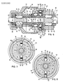
- Fig. 3 einen Schnitt durch die Anordnung nach Fig. 2, gemäss Schnittverlauf III-III;
- Fig. 4 die Anordnung analog Fig. 2 mit gegenüber der Drehspindel entspannten Werkzeughalter;
- Fig. 5 einen Schnitt durch die entspannte Anordnung nach Fig. 4, gemäss Schnittverlauf V-V;
- Fig. 6 eine weitere Ausführungsform eines mit einer Drehspindel verspannten Werkzeughalters im Längsschnitt;
- Fig. 7 einen Schnitt durch die Anordnung nach Fig. 6, gemäss Schnittverlauf VII-VII;
- Fig. 8 einen Schnitt analog Fig. 7 mit gegenüber der Drehspindel entspanntem Werkzeughalter.
- Fig. 1 A handheld device with tool holder in view;
- FIG. 2 shows an enlarged illustration of the tool holder according to FIG. 1 braced with a rotating spindle, partly in longitudinal section;
- 3 shows a section through the arrangement according to FIG. 2, according to section III-III;
- 4 shows the arrangement analogous to FIG. 2 with the tool holder relaxed relative to the rotating spindle;
- 5 shows a section through the relaxed arrangement according to FIG. 4, according to the section VV;
- 6 shows a further embodiment of a tool holder clamped with a rotating spindle in longitudinal section;
- FIG. 7 shows a section through the arrangement according to FIG. 6, according to section VII-VII;
- 8 shows a section analogous to FIG. 7 with the tool holder relaxed relative to the rotating spindle.
Das aus Fig. 1 ersichtliche Handgerät weist ein Gehäuse 1 mit einem seitlich abragendem Handgriff 2 auf. Dem Ein- und Ausschalten des Handgerätes dient ein Drücker 3. Ein insgesamt mit 4 bezeichneter Werkzeughalter ist lösbar mit einer insgesamt mit 5 bezeichneten Drehspindel verbunden.The handheld device shown in FIG. 1 has a housing 1 with a laterally
Der in Fig. 2 vergrössert dargestellte Werkzeughalter 4 verfügt über einen insgesamt mit 6 bezeichneten Futterkörper, eine Stellhülse 7 für Spannbacken 8 und eine insgesamt mit 9 bezeichnete Griffhülse, in welcher eine Ringfeder 11 axial einseitig festgelegt ist. Der Futterkörper 6 weist zur Drehspindel 5 hingewandt einen hülsenförmigen Bereich 12 mit einer Kegelöffnung 13 auf. In Verjüngungsrichtung schliesst sich an die Kegelöffnung 13 eine abgestufte zylindrische Grundbohrung 14 an. In der Zone des erweiterten Auslaufs der Kegelöffnung 13 ist der hülsenförmige Bereich 12 mit drei Durchtrittsöffnungen 15 versehen, die, wie der Fig. 3 entnommen werden kann, in Umfangsrichtung des Futterkörpers 6 gleichmässig verteilt sind. In jeder Durchtrittsöffnung 15 sitzt eine Kugel 16. Radial nach aussen stützen sich die Kugeln 16 an dem freistehenden Abschnitt der Ringfeder 11 ab.The tool holder 4 shown enlarged in FIG. 2 has a chuck body designated overall by 6, an adjusting
Der Futterkörper 6 verfügt ferner aussenseitig über Rastvertiefungen 17 zum Eingriff eines kugeligen Rastkörpers 18 zwecks Festlegens der Griffhülse 9 in einer jeweils funktionsbezogenen Drehstellung gegenüber dem Futterkörper 6. Der Rastkörper 18 ist in einer Aussparung 19 der Griffhülse 9 radial verschiebbar gelagert und von einer Druckfeder 21 beaufschlagt.The
Die Drehspindel 5 ist von einer Zentralbohrung 22 durchsetzt, in welcher, wie der Fig. 3 entnommen werden kann, ein andeutungsweise erkennbarer Schlagübertragungsdöpper 23 geführt ist. Zur Uebertragung von Drehbewegung ist an der Drehspindel 5 eine Keilwellenverzahnung 24 vorgesehen, die mit einer gegengleichen Keilwellenverzahnung 25 am Futterkörper 6 in Eingriff steht. Der freie Endabschnitt 26 der Drehspindel 5 ist als Kegelzapfen 27 ausgebildet, dessen Kegelwinkel mit dem Kegelwinkel der Kegelöffnung 13 korrespondiert. In Erweiterungsrichtung ist der Kegelzapfen 27 durch eine umlaufende Ringnut 28 begrenzt. Die Axialerstreckung der Ringnut 28 verkürzt sich zu deren Grund hin, wobei diese Verkürzung durch entsprechende Neigung einer dem freien Ende des Kegelzapfens 27 zugewandten Flanke 29 erzielt wird. Bei in die Kegelöffnung 13 eingeführtem Kegelzapfen 27 stützen sich die Kugeln 16 unter der Kraft der vorgespannten Ringfeder 11 an der Flanke 29 ab, wodurch ein spielfreies Verspannen des Kegelzapfens 27 in der Kegelöffnung 13 erreicht wird.The
Der Fig. 3 ist ferner zu entnehmen, dass die Ringfeder 11 in Axialprojektion polygonartig ausgebildet ist. Die durch Vorspannung gekrümmten, an der Mantelfläche des hülsenförmigen Bereichs 12 aufliegenden Seitenflächen 31 halten in der in Fig. 2 und 3 gezeigten Drehstellung die Kugeln 16 eingerückt in der Ringnut 28. Durch Drehen der als gleichseitiges Bogendreieck ausgebildeten Ringfeder 11 um 60° gelangen die von der Mantelfläche des Bereichs 12 radial beabstandeten Ecken 32 der Ringfeder 11 in Radialprojektion zu den Kugeln 16. Die Kugeln 16 können somit zu den Ecken 32 hin aus der Ringnut entweichen, wie diese die Fig. 4 und 5 zeigen. In dieser durch Betätigen der Griffhülse 9 erzielten Drehstellung der Ringfeder 11 kann der Werkzeughalter 4 ohne nennenswerten Kraftaufwand und ohne Einsatz von Hilfswerkzeugen von der Drehspindel 5 abgezogen oder gegebenenfalls auf diese aufgesteckt werden. Zum Verspannen wird die Ringfeder 11 wieder um 60° in die den Fig. 2 und 3 entnehmbare Drehstellung gebracht.3 that the
Einen für Drechschlagbetrieb geeigneten insgesamt mit 41 bezeichneten Werkzeughalter zeigen die Fig. 6 bis 8. Dieser sitzt wiederum auf einer insgesamt mit 42 bezeichneten Drehspindel.6 to 8 show a tool holder, generally designated 41 for turning operation. This in turn sits on a rotary spindle, generally designated 42.
Der Werkzeughalter 41 verfügt über einen insgesamt mit 43 bezeichneten Futterkörper, auf dem eine insgesamt mit 44 bezeichnete Griffhülse verdrehbar gelagert ist. Der Futterkörper 43 ist von einer zylindrischen Längsbohrung 45 durchsetzt, an die zur Drehspindel 42 hin eine Kegelöffnung 46 zum Eingriff der Drehspindel 42 anschliesst. Für den spielfreien zentrischen Eingriff weist die Drehspindel 42 einen korrespondierenden Kegelzapfen 47 auf.The
Die Drehspindel 42 ist von einem Schlagübertragungsdöpper 48 durchgriffen, der einerseits der Drehspindel 42 die Drehbewegung vermittelt und andererseits einem in der Längsbohrung 45 geführten Werkzeug 49 Schlagimpulse erteilt.The
Der Drehung ausführende Schlagübertragungsdöpper 48 weist Mitnahmenuten 51 auf, in die walzenförmige Verriegelungselemente 52, die in Durchbrüchen 53 der Drehspindel 42 gelagert sind, zur Uebertragung der Drehbewegung eingreifen. Die Verriegelungselemente 52 werden von einem Stützring 54 in Eingriffsstellung gehalten.The
Der in den Futterkörper 43 eingreifende Abschnitt der Drehspindel 42 ist mit einer umlaufenden Ringnut 55 versehen, deren axiale Erstreckung zum Grund hin sich verkürzt. Zu dieser Verkürzung trägt die Neigung der dem freien Ende der Drehspindel benachbarten Flanke 56 der Ringnut 55 bei. Im Längsabschnitt zwischen der Ringnut 55 und dem Kegelzapfen 47 sind in die Mantelfläche der Drehspindel 42 einander diametral gegenüberliegende muldenförmige Vertiefungen 57 eingebracht.The section of the
Der einen Teil der Drehspindel 42 aufnehmende hülsenförmige Bereich 58 des Futterkörpers 43 ist im freien Endbereich mit sich radial erstreckenden Durchtrittsöffnungen 59 versehen. In diesen ist jeweils eine Kugel 61 verschiebbar gelagert und von einem Tellerfederpaket 62 normal zur Werkzeughalterachse hin beaufschlagt. Das Tellerfederpaket 62 wird durch einen Gleitschuh 63 zur Innenseite 64 der Griffhülse 44 hin abgestützt. In der gezeigten Funktionsstellung ist das Tellerfederpaket 62 gespannt und drückt die Kugel 61 gegen die Flanke 56. Dadurch kommt es zum spielfreien Verspannen des Kegelzapfens 47 in der Kegelöffnung 46.The sleeve-shaped
In die Vertiefungen 57 an der Drehspindel 42 greifen wiederum walzenförmige Verriegelungselemente 65 ein, die in Durchbrüchen 66 des Futterkörpers radial verschiebbar gelagert sind. Die Verriegelungselemente 65 stützen sich radial nach aussen an der Griffhülse 44 ab. Sicherungsringe 67, 68 unterbinden das axiale Verschieben der Griffhülse 44 und des Stützringes 54.In turn, roller-shaped
Auf den Futterkörper 43 ist im freien Endbereich ein Anschlagring 69 aufgeschraubt. Ein elastischer Ring 71 dient dem Abdichten des Werkzeugs 49. Auf dem Futterkörper 43 ist eine Zustellmanschette 72 verschiebbar gelagert. Eine Zylinderfeder 73 treibt die Zustellmanschette 72 in die gezeigte Auflaufstellung gegen den Anschlagring 69. Ein weiterer elastischer Ring 74 dämpft dabei den Aufschlag der Zustellmanschette 72. In Durchbrüchen 75 des Futterkörpers 43 sind weiderum walzenförmige Verriegelungselemente 76 radial verschiebbar gelagert. Diese werden zur Halterung und Drehmitnahme des Werkzeugs 49 in werkzeugseitige Mitnahmenuten 77 eingerückt. Hierzu dient eine an der Zustellmanschette 72 innenseitig vorgesehene Zustellkontur 78. Für das Ausrücken der Verriegelungselemente 76 wird die Zustellmanschette 72 gegen die Kraft der Zylinderfeder 73 zur Drehspindel 42 hin verschoben, wodurch Vertiefungen der Zustellkontur 78 in Radialprojektion zu den Verriegelungselementen 76 gelangen und ein Ausrücken der Verriegelungselemente 76 erlauben.A
Die Fig. 7 und 8 verdeutlichen das Zusammenwirken der Griffhülse 44 mit den Tellerfederpaketen 62. Die Innenseite 64 der Griffhülse 44 weist in Umfangsrichtung sich erstreckende Steuerkonturen 79 auf, die für das Entspannen der Tellerfederpakete 62 und damit für das Ausrücken der Kugeln 61 über Ausweichnischen 81 verfügen. In Spannstellung sind die Ausweichnischen 81, wie der Fig. 7 entnehmbar, ausserhalb der Radialprojektion der Gleitschuhe 63. Durch teilweises Verdrehen der Griffhülse 44 gelangen die Ausweichnischen 81, wie der Fig. 8 entnehmbar, in die Radialprojektion der Gleitschuhe 63, so dass der Werkzeughalter 41 abgezogen bzw aufgesteckt werden kann.7 and 8 illustrate the interaction of the
Claims (8)
Applications Claiming Priority (2)
| Application Number | Priority Date | Filing Date | Title |
|---|---|---|---|
| DE3636027 | 1986-10-23 | ||
| DE19863636027 DE3636027A1 (en) | 1986-10-23 | 1986-10-23 | HAND DEVICE WITH DETACHABLE TOOL HOLDER |
Publications (3)
| Publication Number | Publication Date |
|---|---|
| EP0265380A2 true EP0265380A2 (en) | 1988-04-27 |
| EP0265380A3 EP0265380A3 (en) | 1989-07-05 |
| EP0265380B1 EP0265380B1 (en) | 1991-06-19 |
Family
ID=6312284
Family Applications (1)
| Application Number | Title | Priority Date | Filing Date |
|---|---|---|---|
| EP87810578A Expired - Lifetime EP0265380B1 (en) | 1986-10-23 | 1987-10-07 | Manual apparatus with a removable tool holder |
Country Status (3)
| Country | Link |
|---|---|
| US (1) | US4824298A (en) |
| EP (1) | EP0265380B1 (en) |
| DE (2) | DE3636027A1 (en) |
Cited By (11)
| Publication number | Priority date | Publication date | Assignee | Title |
|---|---|---|---|---|
| EP0448801A1 (en) * | 1990-03-30 | 1991-10-02 | Robert Bosch Gmbh | Portable machine tool with removable tool holder |
| EP0487926A3 (en) * | 1990-11-28 | 1992-09-23 | C. & E. Fein Gmbh & Co. | Motor driven tool |
| EP0556713A3 (en) * | 1992-02-21 | 1993-09-15 | Atlas Copco Elektrowerkzeuge Gmbh | Tool change device on a hand-held machine-tool |
| EP0561246A1 (en) * | 1992-03-18 | 1993-09-22 | Robert Bosch Gmbh | Handheld machine tool with tool holder |
| US5601387A (en) * | 1995-06-07 | 1997-02-11 | Black & Decker Inc. | Depth adjusting system for a power tool |
| US5951026A (en) * | 1997-12-12 | 1999-09-14 | Black & Decker Inc. | Removable chuck |
| WO1999067065A1 (en) * | 1998-06-22 | 1999-12-29 | Azuko Pty. Ltd. | A component mounting method and apparatus for a percussion tool |
| US6079716A (en) * | 1997-12-12 | 2000-06-27 | Black & Decker Inc. | Removable chuck |
| AU743785B2 (en) * | 1998-06-22 | 2002-02-07 | Sandvik Mining And Construction Australia (Production/Supply) Pty Ltd | A component mounting method and apparatus for a percussion tool |
| EP2414121A4 (en) * | 2009-04-03 | 2012-09-26 | Ingersoll Rand Co | Spindle locking assembly |
| CN114700722A (en) * | 2022-04-22 | 2022-07-05 | 博世通(青岛)智能装备有限公司 | A device for automatically changing sleeves for tightening shafts |
Families Citing this family (107)
| Publication number | Priority date | Publication date | Assignee | Title |
|---|---|---|---|---|
| DE4019727A1 (en) * | 1990-06-21 | 1992-02-27 | Licentia Gmbh | Quick-change chuck for portable power drill - has collet which closes onto spindle and eliminates play |
| DE4100186A1 (en) * | 1991-01-05 | 1992-07-09 | Bosch Gmbh Robert | HAND MACHINE TOOL WITH REMOVABLE TOOL HOLDER |
| DE4103663A1 (en) * | 1991-02-07 | 1992-08-20 | Aesculap Ag | SURGICAL HANDPIECE |
| US5110145A (en) * | 1991-06-24 | 1992-05-05 | Stewart Patrick A | Power tool adaptor |
| US5316323A (en) * | 1993-01-08 | 1994-05-31 | Victor Jovanovic | Two-part tool holding fixture |
| AU670373B2 (en) * | 1993-06-30 | 1996-07-11 | Nitto Kohki Co., Ltd. | Annular cutter connecting apparatus and annular cutter |
| US5437465A (en) * | 1993-10-22 | 1995-08-01 | Atlas Copco Elektrowerkzeuge Gmbh | Tool changing device on a hand-operated machine tool |
| DE19521993B4 (en) * | 1995-06-20 | 2009-04-09 | Robert Bosch Gmbh | Tool holder and tool for a drilling and / or percussion machine tool |
| US6036639A (en) * | 1997-04-11 | 2000-03-14 | Minrad Inc. | Laryngoscope having low magnetic susceptibility and method of assembling |
| JPH11104974A (en) * | 1997-10-06 | 1999-04-20 | Makita Corp | Hammering tool |
| US6550786B2 (en) * | 1997-12-12 | 2003-04-22 | Black & Decker Inc. | Removable chuck |
| US6688611B2 (en) * | 1997-12-12 | 2004-02-10 | Black & Decker Inc. | Removable chuck |
| US6551037B2 (en) * | 1997-12-12 | 2003-04-22 | Black & Decker Inc. | Removable chuck |
| DE19945322B8 (en) * | 1999-09-22 | 2004-07-08 | Aesculap Ag & Co. Kg | chuck |
| US6729812B2 (en) * | 1999-12-06 | 2004-05-04 | Theodore G. Yaksich | Power driver having geared tool holder |
| US6357974B1 (en) * | 1999-12-14 | 2002-03-19 | Troy L. Robins | Quick release drill chuck |
| US20030089509A1 (en) * | 2000-01-22 | 2003-05-15 | Helmut Wanek | Hand machine tool |
| US6688610B2 (en) * | 2000-05-12 | 2004-02-10 | Power Tool Holders Incorporated | Chuck with quick change |
| DE10101212A1 (en) * | 2001-01-11 | 2002-07-18 | Roehm Gmbh | chuck |
| US6533291B2 (en) | 2001-02-14 | 2003-03-18 | Power Tool Holders Incorporated | Chuck having quick change mechanism |
| CA2370981C (en) * | 2001-02-14 | 2009-12-29 | Black & Decker Inc. | Removable chuck |
| GB0125749D0 (en) * | 2001-10-26 | 2001-12-19 | Black & Decker Inc | Power tool |
| GB0105547D0 (en) | 2001-03-07 | 2001-04-25 | Black & Decker Inc | Tool holder for a rotary hammer or a chisel hammer |
| US6702090B2 (en) | 2001-03-14 | 2004-03-09 | Milwaukee Electric Tool Corporation | Power tool and spindle lock system |
| DE20105763U1 (en) * | 2001-04-02 | 2001-07-19 | Röhm GmbH, 89567 Sontheim | Drill chuck with a quick coupling |
| DE10127103B4 (en) * | 2001-06-02 | 2008-08-21 | Robert Bosch Gmbh | tool holder |
| US6651990B2 (en) * | 2001-08-06 | 2003-11-25 | Ryobi Ltd. | Tool holder |
| CN2493365Y (en) * | 2001-08-31 | 2002-05-29 | 武进市湟里东方电动工具厂 | Locking mechanism and assembling tool |
| GB0121947D0 (en) * | 2001-09-12 | 2001-10-31 | Black & Decker Inc | Tool holder for hammer |
| US6834864B2 (en) * | 2001-10-24 | 2004-12-28 | Power Tool Holders Incorporated | Chuck having quick change mechanism |
| US7222862B2 (en) * | 2001-10-26 | 2007-05-29 | Black & Decker Inc. | Tool holder |
| US6712368B2 (en) * | 2001-11-08 | 2004-03-30 | S-B Power Tool Company | Quick attachment release system for a rotary hand tool |
| DE10156391C1 (en) * | 2001-11-16 | 2003-01-02 | Bosch Gmbh Robert | Power tool used as a screwdriver or drill comprises a working spindle having a section in the shape of a truncated pyramid which comes into contact with an inner truncated pyramid surface on a tool holder |
| US7063201B2 (en) * | 2001-11-27 | 2006-06-20 | Milwaukee Electric Tool Corporation | Power tool and spindle lock system |
| US7766586B2 (en) * | 2002-12-12 | 2010-08-03 | Derosa John L | Quick change power tool chuck |
| DE10321869A1 (en) * | 2003-05-15 | 2004-12-02 | Robert Bosch Gmbh | Hand tool |
| US20050097717A1 (en) * | 2003-11-06 | 2005-05-12 | Bret Rasmussen | Machining tool |
| EP1533057B1 (en) * | 2003-11-14 | 2007-06-13 | A & M Electric Tools GmbH | Toolholder of a power tool, particularly a screwdriver |
| DE20317695U1 (en) * | 2003-11-14 | 2004-02-19 | Röhm Gmbh | drilling |
| GB2414701A (en) * | 2004-06-05 | 2005-12-07 | Black & Decker Inc | Rotary spindle for a power tool |
| US7455302B2 (en) * | 2004-08-09 | 2008-11-25 | The Jacobs Chuck Manufacturing Company | Chuck with spindle lock |
| US7690658B2 (en) * | 2004-09-20 | 2010-04-06 | Black & Decker Inc. | Tool chuck with power take off feature |
| US20060088393A1 (en) * | 2004-10-26 | 2006-04-27 | Cooper Vincent P | Extended sleeve removable chuck |
| ATE429209T1 (en) * | 2005-02-09 | 2009-05-15 | Safilens S R L | CONTACT LENS, METHOD FOR PRODUCTION THEREOF AND PACKAGE FOR STORING AND CARE OF A CONTACT LENS |
| US7588398B2 (en) * | 2005-04-19 | 2009-09-15 | Black & Decker Inc. | Tool chuck with power take off and dead spindle features |
| US7588399B2 (en) | 2005-09-16 | 2009-09-15 | Black & Decker Inc. | PTO selector mechanism for parallel axis transmission |
| US7537421B2 (en) * | 2005-09-16 | 2009-05-26 | Black & Decker Inc. | Dead spindle PTO with compliant grounding mechanism |
| US7645101B2 (en) * | 2005-09-16 | 2010-01-12 | Black & Decker Inc. | Chuck with internally threaded jaw in a PTO application |
| US7547165B2 (en) * | 2005-09-16 | 2009-06-16 | Black & Decker Inc. | PTO selector mechanism with brake |
| TWM293125U (en) * | 2005-12-07 | 2006-07-01 | Lite On Technology Corp | Torque regulating assembly |
| JP2007326193A (en) * | 2006-06-08 | 2007-12-20 | Hitachi Koki Co Ltd | Impact tool |
| US20070290458A1 (en) * | 2006-06-15 | 2007-12-20 | Shun-Yuan Chuang | Replaceable adapter for an electric hand tool |
| DE102006057928A1 (en) * | 2006-12-08 | 2008-06-12 | Robert Bosch Gmbh | Attachment for a hand tool |
| EP1961522B1 (en) * | 2007-02-23 | 2015-04-08 | Robert Bosch Gmbh | Rotary power tool operable in either an impact mode or a drill mode |
| CN100522427C (en) * | 2007-03-10 | 2009-08-05 | 朱明� | Machine tool quick changing chuck system |
| EP2554616A3 (en) * | 2007-03-27 | 2013-06-26 | Interface, Inc. | System and method for floor covering installation |
| DE102007028486A1 (en) * | 2007-06-21 | 2008-12-24 | Robert Bosch Gmbh | Tool holder for a power tool, in particular for a chisel and / or rotary hammer |
| DE102007000453A1 (en) | 2007-08-20 | 2009-02-26 | Hilti Aktiengesellschaft | Changeable tool holder |
| US7798245B2 (en) | 2007-11-21 | 2010-09-21 | Black & Decker Inc. | Multi-mode drill with an electronic switching arrangement |
| US7735575B2 (en) | 2007-11-21 | 2010-06-15 | Black & Decker Inc. | Hammer drill with hard hammer support structure |
| US7717192B2 (en) | 2007-11-21 | 2010-05-18 | Black & Decker Inc. | Multi-mode drill with mode collar |
| US7770660B2 (en) | 2007-11-21 | 2010-08-10 | Black & Decker Inc. | Mid-handle drill construction and assembly process |
| US7762349B2 (en) | 2007-11-21 | 2010-07-27 | Black & Decker Inc. | Multi-speed drill and transmission with low gear only clutch |
| US7854274B2 (en) | 2007-11-21 | 2010-12-21 | Black & Decker Inc. | Multi-mode drill and transmission sub-assembly including a gear case cover supporting biasing |
| US7717191B2 (en) | 2007-11-21 | 2010-05-18 | Black & Decker Inc. | Multi-mode hammer drill with shift lock |
| WO2009129611A2 (en) * | 2008-04-22 | 2009-10-29 | Gerard Grand | Impact mechanism |
| US8403339B2 (en) | 2008-06-18 | 2013-03-26 | Jacobs Chuck Manufacturing Company | Self tightening chuck with an axial lock |
| US8622401B2 (en) * | 2009-02-27 | 2014-01-07 | Black & Decker Inc. | Bit retention device |
| US8800999B2 (en) * | 2009-02-27 | 2014-08-12 | Black & Decker Inc. | Bit retention device |
| US8381830B2 (en) * | 2009-05-05 | 2013-02-26 | Black & Decker Inc. | Power tool with integrated bit retention device |
| DE102009027223B4 (en) * | 2009-06-26 | 2022-01-13 | Robert Bosch Gmbh | Hand-held power tool with ratchet mechanism |
| US9421679B2 (en) | 2009-06-26 | 2016-08-23 | Robert Bosch Gmbh | Hand-held power tool |
| SE534788C2 (en) * | 2010-04-14 | 2011-12-20 | Anders Johnsen | Coupling device with locking sleeve with radially resilient control means |
| TWM393379U (en) * | 2010-07-23 | 2010-12-01 | Top Gearbox Industry Co Ltd | Switching device for output configuration |
| US8292150B2 (en) | 2010-11-02 | 2012-10-23 | Tyco Healthcare Group Lp | Adapter for powered surgical devices |
| SE535919C2 (en) * | 2011-06-30 | 2013-02-19 | Atlas Copco Ind Tech Ab | Electrically powered tool |
| US9156147B2 (en) | 2012-02-15 | 2015-10-13 | Black & Decker Inc. | Quick change bit holder with ring magnet |
| US10150205B2 (en) | 2012-02-15 | 2018-12-11 | Black & Decker Inc. | Fastening tools with floating magnet sleeves |
| US9943946B2 (en) | 2012-02-15 | 2018-04-17 | Black & Decker Inc. | Tool bits with floating magnet sleeves |
| US9227309B2 (en) | 2012-02-15 | 2016-01-05 | Black & Decker Inc. | Quick change bit holder with ring magnet |
| US9505108B2 (en) | 2012-02-15 | 2016-11-29 | Black & Decker Inc. | Bit holder with floating magnet sleeve |
| US20130214496A1 (en) * | 2012-02-18 | 2013-08-22 | Jack Lin | Chuck |
| US9271705B2 (en) * | 2012-06-14 | 2016-03-01 | Tyrone Vaughn | Surgical instrument adapter with highly secure locking shaft mechanism |
| DE102012211907A1 (en) | 2012-07-09 | 2014-01-09 | Robert Bosch Gmbh | Rotary impact wrench with a striking mechanism |
| US10011008B2 (en) * | 2012-11-15 | 2018-07-03 | Robert Bosch Gmbh | Tool attachment for a hand-held machine tool |
| DE102013213816A1 (en) * | 2012-11-15 | 2014-05-15 | Robert Bosch Gmbh | Tool attachment for a hand tool |
| DE102013213804A1 (en) * | 2012-11-22 | 2014-05-22 | Robert Bosch Gmbh | Tool attachment for a hand tool |
| DE102013210752A1 (en) * | 2012-11-27 | 2014-06-12 | Robert Bosch Gmbh | Hand tool device |
| US10556276B2 (en) | 2013-03-14 | 2020-02-11 | Apex Brands, Inc. | Locking chuck |
| US9883853B2 (en) * | 2013-03-15 | 2018-02-06 | Teleflex Medical Devices S.À.R.L. | Intraosseous device couplers, drivers, kits, and methods |
| DE102013204782A1 (en) * | 2013-03-19 | 2014-09-25 | Robert Bosch Gmbh | Hand tool with a tool holder, which has a polygonal interior shot and a polygonal outdoor shot |
| USD742441S1 (en) | 2013-05-21 | 2015-11-03 | Wilson Tool International Inc. | Punch holder |
| US9815105B2 (en) | 2013-05-21 | 2017-11-14 | Wilson Tool International Inc. | Punch holder and punch configurations |
| JP6467040B2 (en) | 2015-02-16 | 2019-02-06 | ノルグレン オートメーション ソーリューションズ エルエルシーNorgren Automation Solutions,Llc. | Modular machine tool instrument receiver |
| US9981391B2 (en) | 2015-02-16 | 2018-05-29 | Norgren Automation Solutions, Llc | Quick disconnect apparatus for modular tooling |
| USD789761S1 (en) | 2015-11-02 | 2017-06-20 | Black & Decker Inc. | Torsion bit |
| US10442009B2 (en) * | 2017-01-31 | 2019-10-15 | Black & Decker Inc. | Drill with removable chuck |
| DE102017205097B4 (en) * | 2017-03-27 | 2025-04-17 | Robert Bosch Gmbh | Accessory device with locking unit |
| USD898879S1 (en) | 2017-05-01 | 2020-10-13 | Norgren Automation Solutions, Llc | Modular tooling coupler |
| US11034002B2 (en) | 2018-03-23 | 2021-06-15 | Milwaukee Electric Tool Corporation | Attachment mechanism for a power tool |
| CN110421187B (en) * | 2019-08-14 | 2024-04-12 | 重庆机床(集团)有限责任公司 | Self-adaptive positioning clamp |
| CN210686762U (en) * | 2019-08-19 | 2020-06-05 | 北京海益同展信息科技有限公司 | Interlocking mechanism |
| US20210231230A1 (en) * | 2020-01-29 | 2021-07-29 | Stephen E. Finegan, Jr. | Universal stem shaft handle |
| CN111203837A (en) * | 2020-03-10 | 2020-05-29 | 宁波汉浦工具有限公司 | Locking structure and electric screwdriver |
| CN219027426U (en) * | 2020-03-23 | 2023-05-16 | 米沃奇电动工具公司 | Rotary hammer |
| US12589477B2 (en) | 2023-11-30 | 2026-03-31 | Stanley Black & Decker Inc. | Multi-headed power tool and fastening system for same and systems for fastening heads thereon |
| US12594657B2 (en) | 2023-11-30 | 2026-04-07 | Stanley Black & Decker, Inc. | Multi-headed power tool and systems for fastening heads thereon |
Family Cites Families (7)
| Publication number | Priority date | Publication date | Assignee | Title |
|---|---|---|---|---|
| AT233355B (en) * | 1961-09-12 | 1964-05-11 | Metabowerke Kg | Quick change coupling |
| NL294810A (en) * | 1962-09-13 | |||
| US3827510A (en) * | 1972-07-12 | 1974-08-06 | Rockwell International Corp | Power tool |
| SE374288B (en) * | 1973-06-04 | 1975-03-03 | Eminentverktyg Ab | |
| CA1082904A (en) * | 1977-02-09 | 1980-08-05 | Charles R. Johnson | Self-locking chuck |
| DE3310371A1 (en) * | 1983-03-22 | 1984-10-11 | Hilti Ag, Schaan | HAND DEVICE, LIKE DRILL, DRILL, SCREWDRIVER AND THE LIKE |
| DE3413581C2 (en) * | 1984-04-11 | 1986-08-14 | Günter Horst 7927 Sontheim Röhm | Drill chuck |
-
1986
- 1986-10-23 DE DE19863636027 patent/DE3636027A1/en not_active Withdrawn
-
1987
- 1987-10-07 DE DE8787810578T patent/DE3770910D1/en not_active Expired - Lifetime
- 1987-10-07 EP EP87810578A patent/EP0265380B1/en not_active Expired - Lifetime
- 1987-10-22 US US07/112,743 patent/US4824298A/en not_active Expired - Fee Related
Cited By (16)
| Publication number | Priority date | Publication date | Assignee | Title |
|---|---|---|---|---|
| EP0448801A1 (en) * | 1990-03-30 | 1991-10-02 | Robert Bosch Gmbh | Portable machine tool with removable tool holder |
| EP0487926A3 (en) * | 1990-11-28 | 1992-09-23 | C. & E. Fein Gmbh & Co. | Motor driven tool |
| US5180261A (en) * | 1990-11-28 | 1993-01-19 | C. & E. Fein Gmbh & Co. | Motor-operated tool |
| EP0556713A3 (en) * | 1992-02-21 | 1993-09-15 | Atlas Copco Elektrowerkzeuge Gmbh | Tool change device on a hand-held machine-tool |
| EP0561246A1 (en) * | 1992-03-18 | 1993-09-22 | Robert Bosch Gmbh | Handheld machine tool with tool holder |
| US5342154A (en) * | 1992-03-18 | 1994-08-30 | Robert Bosch Gmbh | Hand machine tool with tool holder |
| US5601387A (en) * | 1995-06-07 | 1997-02-11 | Black & Decker Inc. | Depth adjusting system for a power tool |
| US6293559B1 (en) | 1997-12-12 | 2001-09-25 | Black & Decker Inc. | Removable chuck |
| US5951026A (en) * | 1997-12-12 | 1999-09-14 | Black & Decker Inc. | Removable chuck |
| US6079716A (en) * | 1997-12-12 | 2000-06-27 | Black & Decker Inc. | Removable chuck |
| WO1999067065A1 (en) * | 1998-06-22 | 1999-12-29 | Azuko Pty. Ltd. | A component mounting method and apparatus for a percussion tool |
| AU743785B2 (en) * | 1998-06-22 | 2002-02-07 | Sandvik Mining And Construction Australia (Production/Supply) Pty Ltd | A component mounting method and apparatus for a percussion tool |
| US6637520B1 (en) | 1998-06-22 | 2003-10-28 | Azuko Pty Ltd, Acn | Component mounting method and apparatus for a percussion tool |
| EP2414121A4 (en) * | 2009-04-03 | 2012-09-26 | Ingersoll Rand Co | Spindle locking assembly |
| CN114700722A (en) * | 2022-04-22 | 2022-07-05 | 博世通(青岛)智能装备有限公司 | A device for automatically changing sleeves for tightening shafts |
| CN114700722B (en) * | 2022-04-22 | 2023-08-22 | 博世通(青岛)智能装备有限公司 | An automatic sleeve changing device for tightening shaft |
Also Published As
| Publication number | Publication date |
|---|---|
| US4824298A (en) | 1989-04-25 |
| EP0265380A3 (en) | 1989-07-05 |
| DE3636027A1 (en) | 1988-04-28 |
| DE3770910D1 (en) | 1991-07-25 |
| EP0265380B1 (en) | 1991-06-19 |
Similar Documents
| Publication | Publication Date | Title |
|---|---|---|
| EP0265380B1 (en) | Manual apparatus with a removable tool holder | |
| EP0175088B1 (en) | Tool holder for drilling and chipping tools | |
| EP0054774B1 (en) | Chuck | |
| EP0765707B1 (en) | Tool holder for boring and chiseling machine | |
| EP0253761B1 (en) | Chuck for tools | |
| DE10028016B4 (en) | Locking chuck and drive with such a chuck | |
| CH663918A5 (en) | IMPACT DRILLING DEVICE. | |
| DE3422195A1 (en) | IMPACT DRILLING DEVICE | |
| DE10207152A1 (en) | drilling | |
| DE3406668A1 (en) | DRILL CHUCK FOR DRILLING | |
| DE3416986C2 (en) | Drill chucks for hammer drilling | |
| EP0364821A2 (en) | Tool adapter for a machine tool spindle | |
| DE69700028T2 (en) | Clamping device for tool holder with hollow cone | |
| DE8415796U1 (en) | Device for connecting a tool part to a connecting shaft | |
| EP0204654B1 (en) | Drill chuck for hand tools | |
| EP0175065B1 (en) | Adjustable drill chuck | |
| EP3043939A1 (en) | Drill chuck, drilling needle and drilling needle-drill chuck assembly | |
| EP0151551B1 (en) | Chuck for drilling and/or milling tools | |
| EP0316522B1 (en) | Self-gripping chuck | |
| EP0199842B1 (en) | Electropneumatic percussion drill | |
| EP0235607B1 (en) | Keyless chuck for clamp drill-rods or percussion drilling | |
| EP0111787B1 (en) | Insertion of a tool fixed on a machine-tool | |
| DE3744092C2 (en) | Tool holder for drilling and chiseling tools | |
| DE4210911A1 (en) | Quick-coupling mechanism for drill or chisel bits - with spring-loaded connector in which drill shaft and drive shaft are inserted into either end and which can move be moved axially to one another. | |
| DE1602877C3 (en) | Chucks for machine tools |
Legal Events
| Date | Code | Title | Description |
|---|---|---|---|
| PUAI | Public reference made under article 153(3) epc to a published international application that has entered the european phase |
Free format text: ORIGINAL CODE: 0009012 |
|
| AK | Designated contracting states |
Kind code of ref document: A2 Designated state(s): CH DE FR GB LI NL SE |
|
| PUAL | Search report despatched |
Free format text: ORIGINAL CODE: 0009013 |
|
| AK | Designated contracting states |
Kind code of ref document: A3 Designated state(s): CH DE FR GB LI NL SE |
|
| RHK1 | Main classification (correction) |
Ipc: B23B 31/04 |
|
| 17P | Request for examination filed |
Effective date: 19890719 |
|
| 17Q | First examination report despatched |
Effective date: 19901114 |
|
| GRAA | (expected) grant |
Free format text: ORIGINAL CODE: 0009210 |
|
| AK | Designated contracting states |
Kind code of ref document: B1 Designated state(s): CH DE FR GB LI NL SE |
|
| REF | Corresponds to: |
Ref document number: 3770910 Country of ref document: DE Date of ref document: 19910725 |
|
| ET | Fr: translation filed | ||
| GBT | Gb: translation of ep patent filed (gb section 77(6)(a)/1977) | ||
| PLBE | No opposition filed within time limit |
Free format text: ORIGINAL CODE: 0009261 |
|
| STAA | Information on the status of an ep patent application or granted ep patent |
Free format text: STATUS: NO OPPOSITION FILED WITHIN TIME LIMIT |
|
| 26N | No opposition filed | ||
| EAL | Se: european patent in force in sweden |
Ref document number: 87810578.2 |
|
| PGFP | Annual fee paid to national office [announced via postgrant information from national office to epo] |
Ref country code: GB Payment date: 19970926 Year of fee payment: 11 |
|
| PG25 | Lapsed in a contracting state [announced via postgrant information from national office to epo] |
Ref country code: GB Free format text: LAPSE BECAUSE OF NON-PAYMENT OF DUE FEES Effective date: 19981007 |
|
| GBPC | Gb: european patent ceased through non-payment of renewal fee |
Effective date: 19981007 |
|
| PGFP | Annual fee paid to national office [announced via postgrant information from national office to epo] |
Ref country code: SE Payment date: 19990812 Year of fee payment: 13 |
|
| PGFP | Annual fee paid to national office [announced via postgrant information from national office to epo] |
Ref country code: NL Payment date: 19991029 Year of fee payment: 13 |
|
| PG25 | Lapsed in a contracting state [announced via postgrant information from national office to epo] |
Ref country code: SE Free format text: THE PATENT HAS BEEN ANNULLED BY A DECISION OF A NATIONAL AUTHORITY Effective date: 20001030 |
|
| PG25 | Lapsed in a contracting state [announced via postgrant information from national office to epo] |
Ref country code: NL Free format text: LAPSE BECAUSE OF NON-PAYMENT OF DUE FEES Effective date: 20010501 |
|
| EUG | Se: european patent has lapsed |
Ref document number: 87810578.2 |
|
| NLV4 | Nl: lapsed or anulled due to non-payment of the annual fee |
Effective date: 20010501 |
|
| PGFP | Annual fee paid to national office [announced via postgrant information from national office to epo] |
Ref country code: FR Payment date: 20031003 Year of fee payment: 17 |
|
| PG25 | Lapsed in a contracting state [announced via postgrant information from national office to epo] |
Ref country code: FR Free format text: LAPSE BECAUSE OF NON-PAYMENT OF DUE FEES Effective date: 20050630 |
|
| REG | Reference to a national code |
Ref country code: FR Ref legal event code: ST |
|
| PGFP | Annual fee paid to national office [announced via postgrant information from national office to epo] |
Ref country code: DE Payment date: 20060914 Year of fee payment: 20 |
|
| PGFP | Annual fee paid to national office [announced via postgrant information from national office to epo] |
Ref country code: CH Payment date: 20061013 Year of fee payment: 20 |
|
| REG | Reference to a national code |
Ref country code: CH Ref legal event code: PL |