DE202018102220U1 - Spring terminal connection and conductor terminal - Google Patents
Spring terminal connection and conductor terminal Download PDFInfo
- Publication number
- DE202018102220U1 DE202018102220U1 DE202018102220.2U DE202018102220U DE202018102220U1 DE 202018102220 U1 DE202018102220 U1 DE 202018102220U1 DE 202018102220 U DE202018102220 U DE 202018102220U DE 202018102220 U1 DE202018102220 U1 DE 202018102220U1
- Authority
- DE
- Germany
- Prior art keywords
- clamping
- spring
- clamping spring
- cage
- conductor
- Prior art date
- Legal status (The legal status is an assumption and is not a legal conclusion. Google has not performed a legal analysis and makes no representation as to the accuracy of the status listed.)
- Active
Links
- 239000004020 conductor Substances 0.000 title claims abstract description 46
- 239000002184 metal Substances 0.000 claims description 4
- 238000007373 indentation Methods 0.000 description 4
- 238000003780 insertion Methods 0.000 description 3
- 230000037431 insertion Effects 0.000 description 3
- 239000011810 insulating material Substances 0.000 description 2
- 230000002093 peripheral effect Effects 0.000 description 2
- 230000015572 biosynthetic process Effects 0.000 description 1
- 230000001419 dependent effect Effects 0.000 description 1
- 238000011161 development Methods 0.000 description 1
- 230000018109 developmental process Effects 0.000 description 1
- 230000003716 rejuvenation Effects 0.000 description 1
- 238000007493 shaping process Methods 0.000 description 1
Images


Classifications
-
- H—ELECTRICITY
- H01—ELECTRIC ELEMENTS
- H01R—ELECTRICALLY-CONDUCTIVE CONNECTIONS; STRUCTURAL ASSOCIATIONS OF A PLURALITY OF MUTUALLY-INSULATED ELECTRICAL CONNECTING ELEMENTS; COUPLING DEVICES; CURRENT COLLECTORS
- H01R4/00—Electrically-conductive connections between two or more conductive members in direct contact, i.e. touching one another; Means for effecting or maintaining such contact; Electrically-conductive connections having two or more spaced connecting locations for conductors and using contact members penetrating insulation
- H01R4/28—Clamped connections, spring connections
- H01R4/48—Clamped connections, spring connections utilising a spring, clip, or other resilient member
- H01R4/4809—Clamped connections, spring connections utilising a spring, clip, or other resilient member using a leaf spring to bias the conductor toward the busbar
- H01R4/48185—Clamped connections, spring connections utilising a spring, clip, or other resilient member using a leaf spring to bias the conductor toward the busbar adapted for axial insertion of a wire end
- H01R4/4819—Clamped connections, spring connections utilising a spring, clip, or other resilient member using a leaf spring to bias the conductor toward the busbar adapted for axial insertion of a wire end the spring shape allowing insertion of the conductor end when the spring is unbiased
- H01R4/4821—Single-blade spring
-
- H—ELECTRICITY
- H01—ELECTRIC ELEMENTS
- H01R—ELECTRICALLY-CONDUCTIVE CONNECTIONS; STRUCTURAL ASSOCIATIONS OF A PLURALITY OF MUTUALLY-INSULATED ELECTRICAL CONNECTING ELEMENTS; COUPLING DEVICES; CURRENT COLLECTORS
- H01R4/00—Electrically-conductive connections between two or more conductive members in direct contact, i.e. touching one another; Means for effecting or maintaining such contact; Electrically-conductive connections having two or more spaced connecting locations for conductors and using contact members penetrating insulation
- H01R4/28—Clamped connections, spring connections
- H01R4/48—Clamped connections, spring connections utilising a spring, clip, or other resilient member
- H01R4/4809—Clamped connections, spring connections utilising a spring, clip, or other resilient member using a leaf spring to bias the conductor toward the busbar
- H01R4/4828—Spring-activating arrangements mounted on or integrally formed with the spring housing
- H01R4/483—Pivoting arrangements, e.g. lever pushing on the spring
-
- H—ELECTRICITY
- H01—ELECTRIC ELEMENTS
- H01R—ELECTRICALLY-CONDUCTIVE CONNECTIONS; STRUCTURAL ASSOCIATIONS OF A PLURALITY OF MUTUALLY-INSULATED ELECTRICAL CONNECTING ELEMENTS; COUPLING DEVICES; CURRENT COLLECTORS
- H01R4/00—Electrically-conductive connections between two or more conductive members in direct contact, i.e. touching one another; Means for effecting or maintaining such contact; Electrically-conductive connections having two or more spaced connecting locations for conductors and using contact members penetrating insulation
- H01R4/28—Clamped connections, spring connections
- H01R4/48—Clamped connections, spring connections utilising a spring, clip, or other resilient member
- H01R4/4809—Clamped connections, spring connections utilising a spring, clip, or other resilient member using a leaf spring to bias the conductor toward the busbar
- H01R4/4846—Busbar details
- H01R4/4852—Means for improving the contact with the conductor, e.g. uneven wire-receiving surface
Landscapes
- Connections Arranged To Contact A Plurality Of Conductors (AREA)
Abstract
Federkraftklemmanschluss (100) zum Anschließen eines Leiters (L), mit
einer Stromschiene (10),
einer Klemmfeder (11), mittels welcher der anzuschließende Leiter (L) im geklemmten Zustand gegen die Stromschiene (10) geklemmt ist, und
einem schwenkbar angeordneten Betätigungshebel (12), wobei mittels einer Schwenkbewegung des Betätigungshebels (12) die Klemmfeder (11) betätigbar ist,
dadurch gekennzeichnet, dass ein Klemmkäfig (13) vorgesehen ist, welcher einen Aufnahmeraum für den anzuschließenden Leiter (L) ausbildet, und dass die Klemmfeder (11) als Blattfeder ausgebildet ist und einen als Klemmbereich ausgebildeten ersten Endabschnitt (14) und einen dem ersten Endabschnitt (14) gegenüberliegenden, als Haltebereich ausgebildeten zweiten Endabschnitt (15) aufweist, wobei die Klemmfeder (11) mit ihrem zweiten Endabschnitt (15) an dem Klemmkäfig (13) befestigt ist.

a busbar (10),
a clamping spring (11), by means of which the conductor to be connected (L) is clamped in the clamped state against the busbar (10), and
a pivotally arranged actuating lever (12), wherein by means of a pivoting movement of the actuating lever (12), the clamping spring (11) is actuated,
characterized in that a clamping cage (13) is provided, which forms a receiving space for the conductor to be connected (L), and that the clamping spring (11) is designed as a leaf spring and a clamping portion formed as a first end portion (14) and a first end portion (14) opposite, formed as a holding portion second end portion (15), wherein the clamping spring (11) is fastened with its second end portion (15) on the clamping cage (13).
Description
Die Erfindung betrifft einen Federkraftklemmanschluss zum Anschließen eines Leiters, welcher eine Stromschiene, eine Klemmfeder, mittels welcher der anzuschließende Leiter im geklemmten Zustand gegen die Stromschiene geklemmt ist, und einen schwenkbar gelagerten Betätigungshebel aufweist, wobei mittels einer Schwenkbewegung des Betätigungshebels die Klemmfeder betätigbar ist. Weiter betrifft die Erfindung eine Leiteranschlussklemme mit einem entsprechenden Federkraftklemmanschluss.The invention relates to a spring terminal connection for connecting a conductor which a busbar, a clamping spring, by means of which the conductor to be clamped is clamped in the clamped state against the busbar, and a pivotally mounted actuating lever, wherein by means of a pivoting movement of the actuating lever, the clamping spring is actuated. Furthermore, the invention relates to a conductor terminal with a corresponding spring terminal connection.
Leiteranschlussklemmen sind in einer Vielzahl von Varianten bekannt. Üblicherweise wird für den Federkraftklemmanschluss eine als Schenkelfeder ausgebildete Klemmfeder, welche einen Anlageschenkel und einen Klemmschenkel aufweist, verwendet, welche einen anzuschließenden Leiter mit ihrem Klemmschenkel gegen die Stromschiene klemmen kann. Um eine verkippsichere Position der Klemmfeder erreichen zu können, liegt diese üblicherweise mit ihrem Anlageschenkel flächig an einem Isolierstoffgehäuse der Leiteranschlussklemme an. Diese Ausgestaltung erfordert jedoch einen relativ großen Bauraum des Federkraftklemmanschlusses und damit auch der Leiteranschlussklemme.Conductor terminals are known in a variety of variations. Usually, a spring formed as a leg spring clamping spring, which has a plant leg and a clamping leg used for the spring terminal connection, which can clamp a conductor to be connected with its clamping leg against the busbar. In order to achieve a tilt-safe position of the clamping spring, this is usually flat with her plant leg to a Isolierstoffgehäuse the conductor terminal. However, this configuration requires a relatively large space of the spring terminal connection and thus also the conductor terminal.
Der Erfindung liegt daher die Aufgabe zu Grunde, einen Federkraftklemmanschluss sowie eine Leiteranschlussklemme zur Verfügung zu stellen, welche sich durch einen reduzierten Bauraum auszeichnen.The invention is therefore based on the object to provide a Federkraftklemmanschluss and a conductor terminal available, which are characterized by a reduced space.
Die Aufgabe wird erfindungsgemäß mit den Merkmalen der unabhängigen Ansprüche gelöst. Zweckmäßige Ausgestaltungen und vorteilhafte Weiterbildungen der Erfindung sind in den Unteransprüchen angegeben.The object is achieved with the features of the independent claims. Advantageous embodiments and advantageous developments of the invention are specified in the dependent claims.
Der Federkraftklemmanschluss gemäß der Erfindung zeichnet sich dadurch aus, dass ein Klemmkäfig vorgesehen ist, welcher einen Aufnahmeraum für den anzuschließenden Leiter ausbildet, und dass die Klemmfeder als Blattfeder ausgebildet ist und einen als Klemmbereich ausgebildeten ersten Endabschnitt und einen dem ersten Endabschnitt gegenüberliegenden, als Haltebereich ausgebildeten zweiten Endabschnitt aufweist, wobei die Klemmfeder mit ihrem zweiten Endabschnitt an dem Klemmkäfig befestigt ist.The spring terminal connection according to the invention is characterized in that a clamping cage is provided, which forms a receiving space for the conductor to be connected, and that the clamping spring is formed as a leaf spring and a clamping portion formed as a first end portion and the first end portion opposite, formed as a holding area second end portion, wherein the clamping spring is fixed with its second end portion to the clamping cage.
Die Klemmfeder ist nunmehr erfindungsgemäß nicht mehr als Schenkelfeder ausgebildet, sondern die Klemmfeder ist als Blattfeder ausgebildet. Die Blattfeder weist eine blatt- oder streifenförmige Form auf. Da die Blattfeder gegenüber einer Schenkelfeder nur einen Schenkel und nicht zwei Schenkel aufweist, weist diese als Blattfeder ausgebildete Klemmfeder eine kleinere Baugröße auf als eine als Schenkelfeder ausgebildete Klemmfeder. Durch die kleinere Baugröße benötigt sie auch weniger Platz in dem Federkraftklemmanschluss, so dass der gesamte Federkraftklemmanschluss kleinbauender ausgebildet werden kann. Gehalten ist die Klemmfeder nicht an einem Isolierstoffgehäuse, sondern sie ist an einem zusätzlich vorgesehenen Klemmkäfig befestigt bzw. gehalten. Dieser Klemmkäfig bildet auch gleichzeitig einen Aufnahmeraum für den anzuschließenden Leiter aus. Gehalten ist die Klemmfeder an dem Klemmkäfig mit einem zweiten Endabschnitt, welcher einem einen Klemmbereich zum Klemmen des Leiters ausbildenden ersten Endabschnitt gegenüberliegt. Mit dem zweiten Endabschnitt ist die Klemmfeder damit vorzugsweise in einer festen, definierten Position gehalten, wohingegen die Klemmfeder mit ihrem ersten Endabschnitt vorzugweise beweglich, insbesondere verschwenkbar, ist. Um die Federwirkung der Klemmfeder verbessern zu können und/oder um die Montage der Klemmfeder an dem Klemmkäfig vereinfachen zu können, weist die Klemmfeder ausgehend von ihrem ersten Endabschnitt hin zu ihrem zweiten Endabschnitt vorzugsweis eine Querschnittsreduzierung bzw. Verjüngung auf.The clamping spring is now according to the invention no longer designed as a leg spring, but the clamping spring is designed as a leaf spring. The leaf spring has a leaf-shaped or strip-like shape. Since the leaf spring relative to a leg spring has only one leg and not two legs, this clamping spring designed as a leaf spring has a smaller size than a clamping spring formed as a leg spring. Due to the smaller size, it also requires less space in the spring terminal connection, so that the entire spring terminal connection can be made kleinbauender. Held the clamping spring is not attached to a Isolierstoffgehäuse, but it is attached to an additionally provided clamping cage or held. This clamping cage also simultaneously forms a receiving space for the conductor to be connected. Held the clamping spring on the clamping cage with a second end portion, which is opposite to a clamping region for clamping the conductor forming the first end portion. With the second end portion, the clamping spring is thus preferably held in a fixed, defined position, whereas the clamping spring with its first end portion preferably movable, in particular pivotable, is. In order to improve the spring action of the clamping spring and / or to facilitate the assembly of the clamping spring on the clamping cage, the clamping spring, preferably starting from its first end portion towards its second end portion, a cross-sectional reduction or taper.
Zur Befestigung der Klemmfeder an dem Klemmkäfig kann an dem Klemmkäfig eine Öffnung ausgebildet sein, in welcher die Klemmfeder mit ihrem zweiten Endabschnitt eingehangen sein kann. Der zweite Endabschnitt der Klemmfeder kann dafür vorzugsweise gebogen ausgebildet sein, um sich in der Öffnung einhaken zu können. Die Öffnung ist vorzugsweise in Form einer fensterartigen Öffnung ausgebildet. Durch die Befestigung der Klemmfeder in einer Öffnung des Klemmkäfigs kann die Montage der Klemmfeder an dem Klemmkäfig besonders leicht erfolgen, so dass der Montageaufwand verringert werden kann. Zudem nimmt auch die Befestigung der Klemmfeder keinen großen Bauraum in dem Federkraftklemmanschluss ein.For attachment of the clamping spring to the clamping cage, an opening may be formed on the clamping cage, in which the clamping spring may be mounted with its second end portion. The second end portion of the clamping spring may preferably be formed bent to hook in the opening can. The opening is preferably formed in the form of a window-like opening. By attaching the clamping spring in an opening of the clamping cage, the mounting of the clamping spring on the clamping cage can be done very easily, so that the assembly cost can be reduced. In addition, the attachment of the clamping spring does not take up much space in the Federkraftklemmanschluss.
Um auch Leiter mit einem geringen Leiterquerschnitt klemmen zu können, kann an der Stromschiene ein Vorsprung ausgebildet sein, an welchem die Klemmfeder mit ihrem ersten Endabschnitt in einem nicht klemmten Zustand vorgespannt gehalten sein kann. Durch die Vorspannung der Klemmfeder kann die auf die Klemmfeder aufzubringende Kraft beim Überführen der Klemmfeder von dem nicht geklemmten Zustand in den geklemmten Zustand reduziert werden. Der Vorsprung kann in Form einer von der Oberfläche der Stromschiene hervorstehenden Kante ausgebildet sein. Der Vorsprung kann einen Hinterschnitt an der Stromschiene ausbilden, an welchem die Klemmfeder mit ihrem den Klemmbereich ausbildenden ersten Endabschnitt im nicht geklemmten Zustand hinterhaken kann.In order to be able to clamp conductors with a small conductor cross-section, a projection may be formed on the busbar, on which the clamping spring may be held biased by its first end portion in a non-clamped state. By the bias of the clamping spring applied to the clamping spring force can be reduced when transferring the clamping spring from the unclamped state to the clamped state. The projection may be in the form of a protruding from the surface of the busbar edge. The projection can be an undercut at the Form busbar on which the clamping spring with its clamping region forming the first end portion can hook behind in the non-clamped state.
Der Betätigungshebel kann an dem Klemmkäfig schwenkbar gelagert sein. Durch eine Lagerung am Klemmkäfig kann die Baugröße des Federkraftklemmanschlusses weiter reduziert werden. Beispielsweise kann der Betätigungshebel mindestens eine Schwenkachse aufweisen, um die der Betätigungshebel verschwenkt werden kann, wobei es vorgesehen sein kann, dass der Betätigungshebel mit seiner Schwenkachse in eine an dem Klemmkäfig ausgebildete Aussparung eingreift.The actuating lever may be pivotally mounted on the clamping cage. By storage on the clamping cage, the size of the spring terminal connection can be further reduced. For example, the actuating lever may have at least one pivot axis about which the actuating lever can be pivoted, wherein it may be provided that the actuating lever engages with its pivot axis in a recess formed on the clamping cage.
An dem ersten Endabschnitt der Klemmfeder kann eine seitlich an dem ersten Endabschnitt der Klemmfeder angeformte Betätigungsfläche ausgebildet sein, welche zum Betätigen der Klemmfeder mit dem Betätigungshebel zusammenwirken kann. Durch die seitlich angeformte Betätigungsfläche kann die Klemmfeder an ihrem ersten Endabschnitt gegenüber dem zweiten Endabschnitt verbreitert sein. Durch die Betätigungsfläche kann ein Betätigungspunkt des Betätigungselements an der Klemmfeder zum Betätigen der Klemmfeder definiert festgelegt sein, wobei dieser Betätigungspunkt vorzugsweise außerhalb des eigentlichen Klemmbereiches der Klemmfeder zum Klemmen des Leiters positioniert ist. Durch die seitliche Anformung der Betätigungsfläche an dem zweiten Endabschnitt kann jedoch gleichzeitig erreicht werden, dass die Betätigen der Klemmfeder mittels des Betätigungselements auf der Höhe des ersten Endabschnitts und damit des Klemmbereiches erfolgt, so dass der auf die Klemmfeder aufzubringende Kraftaufwand zum Betätigen der Klemmfeder mittels des Betätigungshebels reduziert werden kann.At the first end portion of the clamping spring can be formed laterally integrally formed on the first end portion of the clamping spring actuating surface, which can cooperate for actuating the clamping spring with the actuating lever. Due to the laterally molded actuating surface, the clamping spring can be widened at its first end portion relative to the second end portion. By the actuating surface, an actuating point of the actuating element on the clamping spring for the actuation of the clamping spring defined defined, said actuating point is preferably positioned outside of the actual clamping region of the clamping spring for clamping the conductor. Due to the lateral shaping of the actuating surface on the second end portion, however, can be achieved simultaneously that the actuation of the clamping spring by means of the actuating element at the level of the first end portion and thus of the clamping area, so that the force applied to the clamping spring for actuating the clamping spring by means of Operating lever can be reduced.
Weiter kann es vorgesehen sein, dass an dem Klemmkäfig eine in Form einer fensterartigen Öffnung ausgebildete Führungskontur ausgebildet ist, durch welche die Betätigungsfläche der Klemmfeder hindurchragen kann, so dass die Betätigungsfläche der Klemmfeder mit dem Betätigungshebel außerhalb des Klemmkäfigs zusammenwirken kann. Die Führungskontur kann damit eine gezielte Führung der Klemmfeder beim Überführen in den geklemmten und den nicht geklemmten Zustand der Klemmfeder ausbilden. Ein seitliches Verkippen der Klemmfeder kann dadurch sicher verhindert werden, da der Klemmkäfig eine seitliche Begrenzungswand für die Klemmfeder ausbilden kann. Auch kann durch die Führungskontur der Verschwenkweg, insbesondere die Länge des Verschwenkweges, der Klemmfeder definiert festgelegt werden, so dass ein zu weites Verschwenken der Klemmfeder bzw. ein zu weites Auslenken der Klemmfeder mit ihrem ersten Endabschnitt verhindert werden kann.Further, it may be provided that on the clamping cage formed in the form of a window-like opening guide contour is formed, through which the actuating surface of the clamping spring can protrude so that the actuating surface of the clamping spring can cooperate with the actuating lever outside of the clamping cage. The guide contour can thus form a targeted guidance of the clamping spring during transfer to the clamped and the non-clamped state of the clamping spring. A lateral tilting of the clamping spring can be reliably prevented, since the clamping cage can form a lateral boundary wall for the clamping spring. Also can be defined defined by the guide contour of the Verschwenkweg, in particular the length of the pivoting, the clamping spring, so that too far pivoting of the clamping spring or too far deflection of the clamping spring can be prevented with its first end portion.
Der Klemmkäfig ist bevorzugt aus einem Metall ausgebildet. Durch die Ausbildung aus einem Metall kann die Befestigung der Klemmfeder an dem Klemmkäfig für einen langen Zeitraum sicher erfolgen, da eine Verformung des Klemmkäfigs auch bei einer von der Klemmfeder auf den Klemmkäfig wirkenden Kraft, bspw. durch Betätigen der Klemmfeder, sicher verhindert werden kann.The clamping cage is preferably formed from a metal. Due to the formation of a metal, the attachment of the clamping spring on the terminal cage for a long period of time safely done, as a deformation of the clamping cage can be safely prevented even when acting on the clamping cage of the clamping force, for example. By pressing the clamping spring.
Die Betätigung der Klemmfeder mittels des Betätigungshebels erfolgt vorzugsweise über eine Außenumfangsfläche des Betätigungshebels, welche durch Verschwenken des Betätigungshebels eine Druckkraft auf die Klemmfeder bzw. auf den ersten Endabschnitt der Klemmfeder aufbringen kann. Vorzugsweise weist der Betätigungshebel eine Betätigungsnocke zum Betätigen der Klemmfeder auf, wobei der Betätigungshebel beim Verschwenken des Betätigungshebels mit der Außenfläche der Betätigungsnocke auf der Klemmfeder abgerollt werden kann, um die Klemmfeder zu betätigen.The actuation of the clamping spring by means of the actuating lever is preferably carried out via an outer peripheral surface of the actuating lever, which can apply a compressive force on the clamping spring or on the first end portion of the clamping spring by pivoting the actuating lever. Preferably, the actuating lever has an actuating cam for actuating the clamping spring, wherein the actuating lever when pivoting the actuating lever with the outer surface of the actuating cam on the clamping spring can be unrolled to actuate the clamping spring.
Die Lösung der erfindungsgemäßen Aufgabe erfolgt ferner mittels einer Leiteranschlussklemme, welche ein Gehäuse aufweist, in welchem ein Federkraftklemmanschluss angeordnet ist, welcher wie vorstehend beschrieben, aus- und weitergebildet ist. Das Gehäuse ist vorzugsweise aus einem Isolierstoffmaterial, beispielsweise einem Kunststoff, ausgebildet. Durch die kompaktere Ausbildung des Federkraftklemmanschlusses kann auch das den Federkraftklemmanschluss umgebende Gehäuse kompakter ausgebildet sein, wodurch die gesamte Leiteranschlussklemme kompakter ausgebildet sein kann.The solution of the object according to the invention also takes place by means of a conductor connection terminal, which has a housing in which a spring force terminal connection is arranged, which is as described above, and further developed. The housing is preferably formed from an insulating material, for example a plastic. Due to the more compact design of the spring terminal connection and the housing surrounding the spring terminal connection can be made more compact, whereby the entire conductor terminal can be made more compact.
Um zudem die Handhabung der Leiteranschlussklemme für einen Benutzer verbessern zu können, kann das Gehäuse einen Rastbereich aufweisen, an welchem der Betätigungshebel verrastbar sein kann. Durch die Verrastung kann eine definierte, festgelegte Position des Betätigungshebels relativ zu dem Gehäuse in einem nicht betätigten Zustand des Betätigungshebels erreicht werden.In addition, in order to be able to improve the handling of the conductor terminal for a user, the housing may have a latching region, on which the actuating lever can be latched. By locking a defined, fixed position of the actuating lever can be achieved relative to the housing in a non-actuated state of the actuating lever.
Nachfolgend wird die Erfindung unter Bezugnahme auf die anliegenden Zeichnungen anhand bevorzugter Ausführungsformen näher erläutert.The invention will be explained in more detail with reference to the accompanying drawings with reference to preferred embodiments.
Es zeigen:
-
1 eine schematische Darstellung eines Federkraftklemmanschlusses gemäß der Erfindung in einer Vorderansicht, -
2 eine schematische Darstellung des Federkraftklemmanschlusses gemäß1 in einer Rückansicht, -
3 eine weitere schematische Darstellung des in1 gezeigten Federkraftklemmanschlusses in einer Vorderansicht, -
4 eine weitere schematische Darstellung des in1 gezeigten Federkraftklemmanschlusses in einer Rückansicht, -
5 eine schematische Darstellung einer Rückansicht eines wie in1 gezeigten Federkraftklemmanschlusses mit einem angeschlossenen Leiter, -
6 eine schematische Darstellung einer perspektivischen Ansicht eines wie in1 gezeigten Federkraftklemmanschlusses mit einem angeschlossenen Leiter, -
7 eine schematische Darstellung einer Leiteranschlussklemme gemäß der Erfindung mit einem angeschlossenen Leiter, -
8 eine weitere schematische Darstellung der in7 gezeigten Leiteranschlussklemme, -
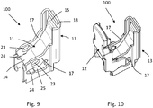
9 eine schematische Darstellung einer weiteren Ausführungsvariante des Federkraftklemmanschlusses gemäß der Erfindung, und -
10 eine weitere schematische Darstellung des in9 gezeigten Federkraftklemmanschlusses.
-
1 1 is a schematic representation of a spring-force clamping connection according to the invention in a front view, -
2 a schematic representation of the Federkraftklemmanschlusses according to1 in a rear view, -
3 another schematic representation of the in1 shown Federkraftklemmanschlusses in a front view, -
4 another schematic representation of the in1 shown Federkraftklemmanschlusses in a rear view, -
5 a schematic representation of a rear view of a as in1 shown Federkraftklemmanschlusses with a connected conductor, -
6 a schematic representation of a perspective view of a as in1 shown Federkraftklemmanschlusses with a connected conductor, -
7 a schematic representation of a conductor terminal according to the invention with a connected conductor, -
8th another schematic representation of in7 shown conductor terminal, -
9 a schematic representation of another embodiment of the spring terminal connection according to the invention, and -
10 another schematic representation of the in9 shown spring force terminal connection.
Die Klemmfeder
Die Stromschiene
Der Klemmkäfig
Die zweite Wand
Die Klemmfeder
Die Klemmkäfig
Zum Betätigen der Klemmfeder
Die Klemmfeder
An dem Klemmkäfig
Der Betätigungshebel
Der Betätigungshebel
Ist der anzuschließende Leiter
Ist ein Leiter L angeschlossen, hat der Betätigungshebel
BezugszeichenlisteLIST OF REFERENCE NUMBERS
Claims (10)
Priority Applications (1)
| Application Number | Priority Date | Filing Date | Title |
|---|---|---|---|
| DE202018102220.2U DE202018102220U1 (en) | 2018-04-20 | 2018-04-20 | Spring terminal connection and conductor terminal |
Applications Claiming Priority (1)
| Application Number | Priority Date | Filing Date | Title |
|---|---|---|---|
| DE202018102220.2U DE202018102220U1 (en) | 2018-04-20 | 2018-04-20 | Spring terminal connection and conductor terminal |
Publications (1)
| Publication Number | Publication Date |
|---|---|
| DE202018102220U1 true DE202018102220U1 (en) | 2019-07-23 |
Family
ID=67550692
Family Applications (1)
| Application Number | Title | Priority Date | Filing Date |
|---|---|---|---|
| DE202018102220.2U Active DE202018102220U1 (en) | 2018-04-20 | 2018-04-20 | Spring terminal connection and conductor terminal |
Country Status (1)
| Country | Link |
|---|---|
| DE (1) | DE202018102220U1 (en) |
Cited By (1)
| Publication number | Priority date | Publication date | Assignee | Title |
|---|---|---|---|---|
| WO2022243284A3 (en) * | 2021-05-19 | 2023-02-02 | Wago Verwaltungsgesellschaft Mbh | Lead terminal comprising at least one spring-loaded clamping connection |
-
2018
- 2018-04-20 DE DE202018102220.2U patent/DE202018102220U1/en active Active
Cited By (1)
| Publication number | Priority date | Publication date | Assignee | Title |
|---|---|---|---|---|
| WO2022243284A3 (en) * | 2021-05-19 | 2023-02-02 | Wago Verwaltungsgesellschaft Mbh | Lead terminal comprising at least one spring-loaded clamping connection |
Similar Documents
| Publication | Publication Date | Title |
|---|---|---|
| DE102014114026B4 (en) | Conductor terminal and method of assembly | |
| DE2709604C2 (en) | ||
| DE102008039232B4 (en) | Electrical connection terminal | |
| EP2324533B1 (en) | Electrical connection terminal | |
| DE102022100132A1 (en) | Electrical connection device | |
| EP3298659A1 (en) | Conductor connection terminal | |
| EP3843221B1 (en) | Supporting frame for a connector | |
| DE102016112831B4 (en) | Connection terminal | |
| WO2017081197A1 (en) | Plug contact | |
| DE102008033325A1 (en) | Electrical connecting terminal e.g. tension spring clamp, for connecting electrical cable, has housing provided with cable entry opening, and clamping spring swiveled from position to other position during shifting of actuating slide | |
| WO2019052852A1 (en) | CONNECTION DEVICE FOR CONNECTING AN ELECTRICAL LINE | |
| DE102020126486A1 (en) | Holding frame for a connector | |
| DE202018102220U1 (en) | Spring terminal connection and conductor terminal | |
| DE102024134941A1 (en) | Spring clamp connection, conductor connection terminal and guide sleeve | |
| DE102018109545A1 (en) | Spring terminal connection and conductor terminal | |
| DE202017105162U1 (en) | Conductor terminal | |
| DE2706988A1 (en) | Bared wire ends connection system - has slider acting on V=shaped leaf spring which used to retain wire | |
| LU501611B1 (en) | Current bar and connection arrangement with such a current bar | |
| DE102025102742A1 (en) | Spring-cage terminal and conductor connection terminal | |
| DE202024102624U1 (en) | conductor connection terminal | |
| DE202024102627U1 (en) | conductor connection terminal | |
| DE102017115865A1 (en) | Connecting device for connecting an electrical line | |
| DE202023101684U1 (en) | Self-locking spring clamp connection and terminal equipped with it | |
| DE102017118638B4 (en) | Cable lug and terminal | |
| DE102024126138A1 (en) | Spring-cage terminal and conductor connection terminal |
Legal Events
| Date | Code | Title | Description |
|---|---|---|---|
| R207 | Utility model specification | ||
| R150 | Utility model maintained after payment of first maintenance fee after three years | ||
| R151 | Utility model maintained after payment of second maintenance fee after six years |