DE112006000360T5 - Automatic ultrasonic testing device, automatic ultrasonic testing method and manufacturing method using the testing method - Google Patents

Automatic ultrasonic testing device, automatic ultrasonic testing method and manufacturing method using the testing method Download PDF

Info

Publication number
DE112006000360T5
DE112006000360T5 DE112006000360T DE112006000360T DE112006000360T5 DE 112006000360 T5 DE112006000360 T5 DE 112006000360T5 DE 112006000360 T DE112006000360 T DE 112006000360T DE 112006000360 T DE112006000360 T DE 112006000360T DE 112006000360 T5 DE112006000360 T5 DE 112006000360T5
Authority
DE
Germany
Prior art keywords
spot
ultrasonic testing
center
test
welded
Prior art date
Legal status (The legal status is an assumption and is not a legal conclusion. Google has not performed a legal analysis and makes no representation as to the accuracy of the status listed.)
Granted
Application number
DE112006000360T
Other languages
German (de)
Other versions
DE112006000360B4 (en
Inventor
Hideki Neyagawa Tanishiki
Current Assignee (The listed assignees may be inaccurate. Google has not performed a legal analysis and makes no representation or warranty as to the accuracy of the list.)
Exedy Corp
Original Assignee
Exedy Corp
Priority date (The priority date is an assumption and is not a legal conclusion. Google has not performed a legal analysis and makes no representation as to the accuracy of the date listed.)
Filing date
Publication date
Application filed by Exedy Corp filed Critical Exedy Corp
Publication of DE112006000360T5 publication Critical patent/DE112006000360T5/en
Application granted granted Critical
Publication of DE112006000360B4 publication Critical patent/DE112006000360B4/en
Anticipated expiration legal-status Critical
Expired - Fee Related legal-status Critical Current

Links

Classifications

    • GPHYSICS
    • G01MEASURING; TESTING
    • G01NINVESTIGATING OR ANALYSING MATERIALS BY DETERMINING THEIR CHEMICAL OR PHYSICAL PROPERTIES
    • G01N29/00Investigating or analysing materials by the use of ultrasonic, sonic or infrasonic waves; Visualisation of the interior of objects by transmitting ultrasonic or sonic waves through the object
    • G01N29/22Details, e.g. general constructional or apparatus details
    • G01N29/26Arrangements for orientation or scanning by relative movement of the head and the sensor
    • G01N29/265Arrangements for orientation or scanning by relative movement of the head and the sensor by moving the sensor relative to a stationary material
    • GPHYSICS
    • G01MEASURING; TESTING
    • G01NINVESTIGATING OR ANALYSING MATERIALS BY DETERMINING THEIR CHEMICAL OR PHYSICAL PROPERTIES
    • G01N29/00Investigating or analysing materials by the use of ultrasonic, sonic or infrasonic waves; Visualisation of the interior of objects by transmitting ultrasonic or sonic waves through the object
    • G01N29/04Analysing solids
    • G01N29/043Analysing solids in the interior, e.g. by shear waves
    • GPHYSICS
    • G01MEASURING; TESTING
    • G01NINVESTIGATING OR ANALYSING MATERIALS BY DETERMINING THEIR CHEMICAL OR PHYSICAL PROPERTIES
    • G01N29/00Investigating or analysing materials by the use of ultrasonic, sonic or infrasonic waves; Visualisation of the interior of objects by transmitting ultrasonic or sonic waves through the object
    • G01N29/22Details, e.g. general constructional or apparatus details
    • G01N29/225Supports, positioning or alignment in moving situation
    • GPHYSICS
    • G01MEASURING; TESTING
    • G01NINVESTIGATING OR ANALYSING MATERIALS BY DETERMINING THEIR CHEMICAL OR PHYSICAL PROPERTIES
    • G01N29/00Investigating or analysing materials by the use of ultrasonic, sonic or infrasonic waves; Visualisation of the interior of objects by transmitting ultrasonic or sonic waves through the object
    • G01N29/44Processing the detected response signal, e.g. electronic circuits specially adapted therefor
    • G01N29/4445Classification of defects
    • GPHYSICS
    • G01MEASURING; TESTING
    • G01NINVESTIGATING OR ANALYSING MATERIALS BY DETERMINING THEIR CHEMICAL OR PHYSICAL PROPERTIES
    • G01N2291/00Indexing codes associated with group G01N29/00
    • G01N2291/26Scanned objects
    • G01N2291/267Welds
    • G01N2291/2672Spot welding
    • GPHYSICS
    • G01MEASURING; TESTING
    • G01NINVESTIGATING OR ANALYSING MATERIALS BY DETERMINING THEIR CHEMICAL OR PHYSICAL PROPERTIES
    • G01N2291/00Indexing codes associated with group G01N29/00
    • G01N2291/26Scanned objects
    • G01N2291/269Various geometry objects
    • G01N2291/2693Rotor or turbine parts

Landscapes

  • Physics & Mathematics (AREA)
  • Biochemistry (AREA)
  • Health & Medical Sciences (AREA)
  • Life Sciences & Earth Sciences (AREA)
  • Chemical & Material Sciences (AREA)
  • Analytical Chemistry (AREA)
  • General Health & Medical Sciences (AREA)
  • General Physics & Mathematics (AREA)
  • Immunology (AREA)
  • Pathology (AREA)
  • Acoustics & Sound (AREA)
  • Engineering & Computer Science (AREA)
  • Signal Processing (AREA)
  • Investigating Or Analyzing Materials By The Use Of Ultrasonic Waves (AREA)

Abstract

Automatische Ultraschallprüfvorrichtung zum automatischen Kontrollieren der Qualität eines punktgeschweißten Bereichs eines Prüfobjekts, umfassend:
ein Ultraschallprüfinstrument mit einer Ultraschallsonde zum Senden von Ultraschallwellen und zum Erfassen von reflektierten Wellen während ihres Kontakts mit dem punktgeschweißten Bereich und mit einer Ultraschallprüfinstrumenthauptvorrichtung, die mit der Ultraschallsonde verbunden ist, zum Konvertieren von der Ultraschallsonde empfangenen Reflexionswellenerfassungssignale in Prüfinformationen;
einen Roboterarm mit einer Mehrzahl von Gelenken zum dreidimensionalen Einstellen der Stellung und Lage der Ultraschallsonde relativ zu dem punktgeschweißten Bereich; und
eine mit dem Ultraschallprüfinstrument und dem Roboterarm verbundene Steuerungsvorrichtung zur Daten- und Signalkommunikation mit dem Ultraschallprüfinstrument und dem Roboterarm;
wobei die Steuerungsvorrichtung eine Tatsächliche-Mitte-Identifizierungseinheit zum Identifizieren der tatsächlichen Mitte des punktgeschweißten Bereichs mit Bezug auf einzelne Prüfinformationen, die rund um eine voreingestellte vorläufige Mitte des punktgeschweißten Bereichs erhalten werden, und eine Bestimmungseinheit zum Kontrollieren der Qualität des punktgeschweißten Bereichs mit Bezug auf die an der tatsächlichen Mitte erhaltenen Prüfinformationen...
Automatic ultrasonic testing apparatus for automatically controlling the quality of a spot-welded area of a test object, comprising:
an ultrasonic testing instrument having an ultrasonic probe for transmitting ultrasonic waves and detecting reflected waves during their contact with the spot-welded portion and having an ultrasonic testing instrument main device connected to the ultrasonic probe for converting reflection wave detection signals received by the ultrasonic probe into inspection information;
a robot arm having a plurality of hinges for three-dimensionally adjusting the position and attitude of the ultrasound probe relative to the spot-welded region; and
a control device connected to the ultrasonic testing instrument and the robot arm for data and signal communication with the ultrasonic testing instrument and the robot arm;
wherein the control device has an actual center identification unit for identifying the actual center of the spot welded area with respect to individual inspection information obtained around a preset preliminary center of the spot welded area and a quality control unit of the spot welded area with reference to FIG test information obtained at the actual center ...
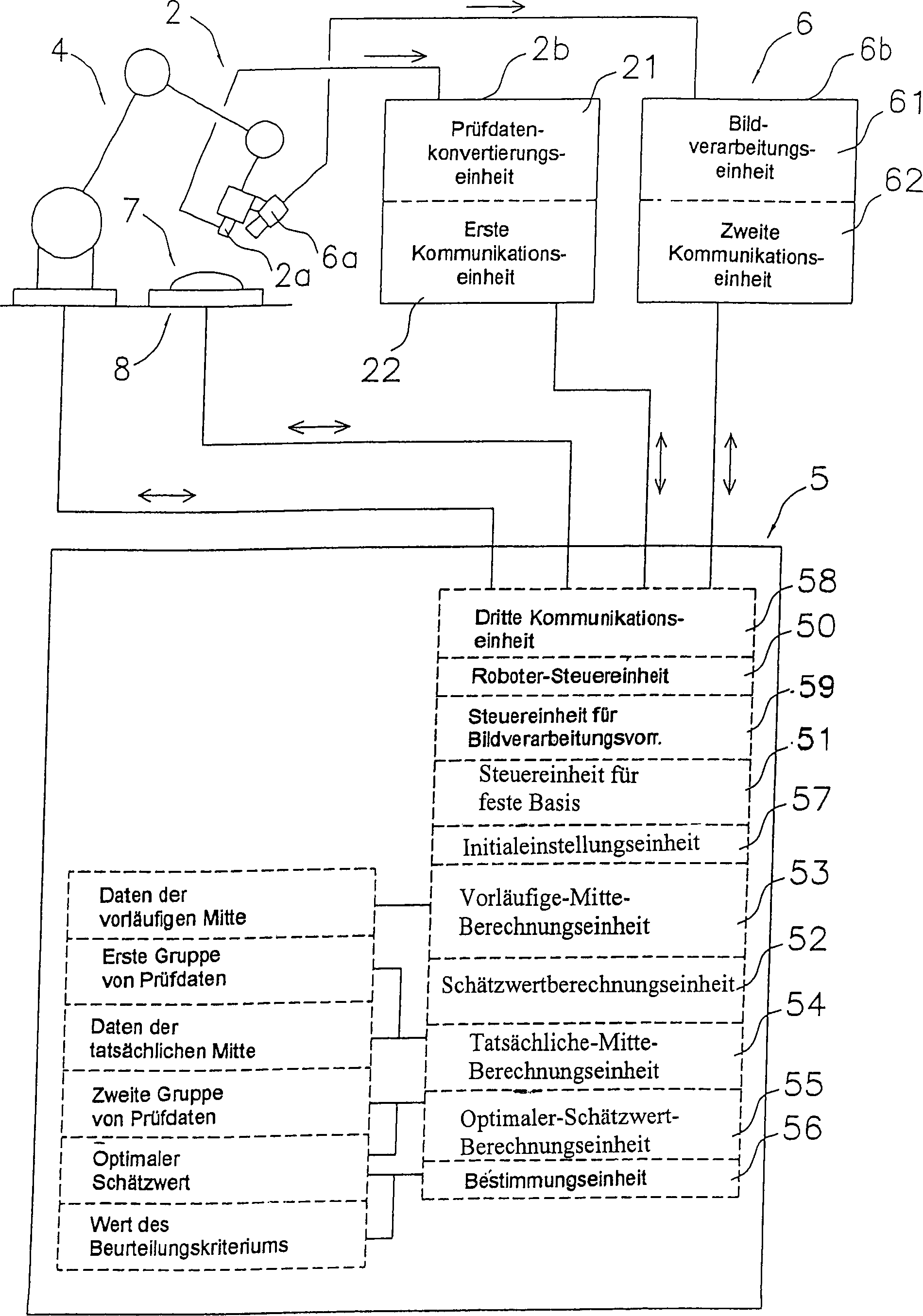
Figure 00000001
Figure 00000001

Description

Technisches GebietTechnical area

Die vorliegende Erfindung betrifft eine automatische Ultraschallprüfvorrichtung, ein automatisches Ultraschallprüfverfahren und ein Herstellungsverfahren, bei welchem das Prüfverfahren angewendet wird. Die Erfindung betrifft insbesondere solche automatische Verfahren, bei denen Roboter zum Einsatz kommen.The The present invention relates to an automatic ultrasonic testing apparatus, an automatic ultrasonic test procedure and a manufacturing method in which the test method is applied. The invention particularly relates to such automatic Methods in which robots are used.

Technischer HintergrundTechnical background

Es ist ein Verfahren allgemein bekannt, das Ultraschallprüfinstrumente für die zerstörungsfreie Prüfung von punktgeschweißten Bereichen anwendet. Das Ultraschallprüfinstrument weist beispielsweise eine Ultraschallsonde, die Ultraschallwellen aussendet und die reflektierten Ultraschallwellen erfasst, während die Sonde mit punktgeschweißten Bereichen in Kontakt ist, und ein mit der Ultraschallsonde verbundenes Ultraschallprüfinstrumenthauptvorrichtung des Ultraschallprüfinstruments auf, das von der Ultraschallsonde Signale einer erfassten reflektierten Welle empfängt und diese Signale in Prüfdaten umwandelt. Da Ultraschallwellen bei dem Ultraschallprüfinstrument durch eine in dem punktgeschweißten Bereich gebildete Schweißlinse gedämpft wird, ist es möglich, die Qualität der geschweißten Bereiche zu kontrollieren (siehe zum Beispiel Patentdokument 1).

  • Patentdokument 1: Ungeprüfte JP Patentpublikation H11-326287
A method is generally known which uses ultrasonic testing instruments for nondestructive testing of spot welded areas. The ultrasonic testing instrument includes, for example, an ultrasonic probe which emits ultrasonic waves and detects the reflected ultrasonic waves while the probe is in contact with spot-welded portions, and an ultrasonic inspection instrument main device of the ultrasonic inspection instrument connected to the ultrasonic probe which receives signals of a detected reflected wave from the ultrasonic probe and these signals converted into test data. Since ultrasonic waves in the ultrasonic testing instrument are damped by a nugget formed in the spot-welded portion, it is possible to control the quality of the welded portions (for example, see Patent Document 1).
  • Patent Document 1: Unexamined Japanese Patent Publication H11-326287

Offenbarung der ErfindungDisclosure of the invention

Durch die Erfindung zu lösendes ProblemProblem to be solved by the invention

Um die punktgeschweißten Bereiche präzise prüfen zu können, ist es erforderlich, dass die Ultraschallsonde für eine Ultraschallprüfung mit der Mitte der Schweißlinse in Kontakt gelangt. Die genaue Mitte der Schweißlinse unterscheidet sich jedoch in vielen Fällen von der augenscheinlichen Mitte von Schweißnarben, so dass es schwierig ist, die genaue Mitte nur durch Augenschein zu identifizieren. Selbst wenn die genaue Mitte identifiziert ist, ist es, da die Intensität der reflektierten Wellen relativ zu der Schweißlinse abhängig von den Einfallswinkeln der Ultraschallwellen unterschiedlich ist, schwierig, die Qualität der punktgeschweißten Bereiche genau zu kontrollieren, ist mühsam, den Winkel der Ultraschallsonde einzustellen. Speziell wenn der punktgeschweißte Bereich an einer gekrümmten Oberfläche gebildet ist, benötigt dies viele Arbeitsstunden. Wenn also der Prüfvorgang von einer Bedienungsperson durchgeführt wird, verschlechtern sich die Genauigkeit und die Effizienz der Qualitätskontrolle ganz enorm.Around the point-welded Being able to examine areas precisely is It required that the ultrasound probe be used for ultrasonic testing the center of the weld nugget got in contact. However, the exact center of the weld lens differs in many cases from the apparent center of sweat marks, making it difficult is to identify the exact center only by visual inspection. Even if the exact middle is identified, it is because the intensity of the reflected Waves relative to the weld nugget dependent is different from the angles of incidence of the ultrasonic waves, difficult, the quality the point-welded Precisely controlling areas is troublesome, the angle of the ultrasound probe adjust. Especially when the spot-welded portion is formed on a curved surface is needed this many working hours. So if the inspection is done by an operator, deteriorate the accuracy and efficiency of quality control very huge.

Obwohl eine Vorrichtung vorgeschlagen wurde, die den Prüfvorgang mit Robotern durchführt, fehlt ein Verfahren zur effizienten und hochgenauen Identifizierung der Mitte der Schweißlinse in dem punktgeschweißten Bereich oder zur Einstellung des optimalen Einfallswinkels der Ultraschallwellen.Even though a device has been proposed which performs the testing process with robots is missing a method for efficient and highly accurate identification of the Center of the weld nugget in the point-welded Range or to adjust the optimal angle of incidence of the ultrasonic waves.

Es ist eine Aufgabe der vorliegenden Erfindung, die Qualität von punktgeschweißten Bereichen unter Verwendung eines Ultraschallprüfinstruments mit hoher Genauigkeit und hoher Geschwindigkeit zu kontrollieren.It It is an object of the present invention to reduce the quality of spot welded areas Using an ultrasonic test instrument with high accuracy and high speed control.

Lösung des Problemsthe solution of the problem

Es wird eine automatische Ultraschallprüfvorrichtung gemäß Anspruch 1 vorgeschlagen, um einen punktgeschweißten Bereich eines Prüfobjekts automatisch zu prüfen. Die Vorrichtung weist ein Ultraschallprüfinstrument, einen Roboterarm und eine Steuervorrichtung auf. Das Ultraschallprüfinstrument weist eine Ultraschallsonde zum Senden von Ultraschallwellen und zum Erfassen von reflektierten Ultraschallwellen während des Kontakts der Sonde mit dem punktgeschweißten Bereich und eine mit der Ultraschallsonde verbundene Ultraschallprüfinstrumenthauptvorrichtung zum Konvertieren der von der Ultraschallsonde empfangenen Erfassungssignale der reflektierten Wellen in Prüfinformationen auf. Der Roboterarm hat eine Mehrzahl von Gelenken zum dreidimensionalen Einstellen der Stellung und Lage der Ultraschallsonde relativ zu dem punktgeschweißten Bereich. Die Steuerungsvorrichtung ist mit dem Ultraschallprüfinstrument und mit dem Roboterarm verbunden, zur Daten- und Signalkommunikation mit dem Ultraschallprüfinstrument und mit dem Roboterarm. Die Steuerungsvorrichtung hat eine Tatsächliche-Mitte-Identifizierungseinheit zum Identifizieren einer Position einer tatsächlichen Mitte des punktgeschweißten Bereichs mit Bezug auf Prüfinformationen, die rund um eine voreingestellte vorläufige Mitte des punktgeschweißten Bereichs erhalten werden, und eine Bestimmungseinheit zum Kontrollieren der Qualität des punktgeschweißten Bereichs mit Bezugnahme auf die an der tatsächlichen Mitte erhaltenen Prüfinformationen.It is an automatic ultrasonic testing device according to claim 1 proposed to automatically detect a point-welded area of a test object to consider. The device has an ultrasonic testing instrument, a robotic arm and a control device. The ultrasonic test instrument points an ultrasonic probe for transmitting ultrasonic waves and detecting of reflected ultrasonic waves during the contact of the probe with the point-welded Area and connected to the ultrasonic probe Ultraschallprüfinstrumenthauptvorrichtung for converting the detection signals received from the ultrasonic probe reflected waves in test information on. The robot arm has a plurality of joints for three-dimensional Adjusting the position and position of the ultrasound probe relative to the point-welded Area. The control device is with the ultrasonic testing instrument and connected to the robot arm for data and signal communication with the ultrasonic testing instrument and with the robot arm. The control device has an actual center identification unit for identifying a position of an actual center of the spot-welded area with regard to test information, around a pre-set preliminary center of the spot-welded area and a determination unit for controlling the quality of the spot-welded area with reference to the test information obtained at the actual center.

Da bei der automatischen Ultraschallprüfvorrichtung die Tatsächliche-Mitte-Identifizierungseinheit die tatsächliche Mitte des punktgeschweißten Bereichs, d.h. die durch bloßen Augenschein nicht zu beurteilende Mitte einer Schweißlinse, identifizieren kann, ist es möglich, die Qualität des punktgeschweißten Bereichs mit einem ungleich höheren Grad an Genauigkeit zu prüfen als bei Durchführung der Prüfung durch die Bedienungsperson. Zusätzlich ermöglicht der automatische Betrieb durch die Steuerungsvorrichtung und den Roboterarm einen Betrieb mit einer im Vergleich zur einer Durchführung durch die Bedienperson hohen Geschwindigkeit.There in the automatic ultrasonic inspection device, the actual center identification unit the actual Middle of the spot-welded area, i.e. by mere Inspection center of a weld nugget, can identify, it is possible the quality the point-welded Area with a much higher degree to check for accuracy than when carrying out the exam by the operator. In addition, the automatic operation by the control device and the robot arm an operation with one in comparison to one implementation by the operator high speed.

Es wird eine automatische Ultraschallprüfvorrichtung gemäß dem von Anspruch 1 abhängigen Anspruch 2 vorgeschlagen, bei der die Steuerungsvorrichtung eine Optimal-Prüfinformation-Einheit aufweist, um eine Prüfinformation zu erhalten, die zum Kontrollieren der Qualität des punktgeschweißten Bereichs in Bezug auf einzelne Prüfinformationen optimal ist, die rund um die zentrale Achse der tatsächlichen Mitte erhalten werden, während eine Schwenkbewegung an einem Kontaktpunkt zwischen der Ultraschallsonde und der tatsächlichen Mitte vorgenommen wird. Die Bestimmungseinheit kontrolliert die Qualität des punktgeschweißten Bereichs mit Bezug auf die optimale Prüfinformationen.It an automatic ultrasonic testing device according to the Claim 1 dependent claim 2, in which the control device is an optimum check information unit has to check information to get that to control the quality of the spot welded area in terms of individual test information optimal, which is around the central axis of the actual Middle to be obtained while a pivoting movement at a contact point between the ultrasound probe and the actual middle is made. The determination unit controls the quality of the spot-welded area with reference to the optimal test information.

Da bei der automatischen Ultraschallprüfvorrichtung die Bestimmungseinheit die Qualitätskontrolle mit Bezug auf die optimale Prüfinformation durchführt, ist diese Qualitätskontrolle durch die Bestimmungseinheit mit hoher Genauigkeit möglich.There in the automatic ultrasonic testing apparatus, the determining unit the quality control with respect to performing the optimal check information is this quality control possible by the determination unit with high accuracy.

Es wird eine automatische Ultraschallprüfvorrichtung gemäß dem von Anspruch 1 oder 2 abhängigen Anspruch 3 vorgeschlagen, bei welcher der Ort und die Anzahl von Prüfpunkten durch die Steuerungsvorrichtung voreingestellt werden können.It an automatic ultrasonic testing device according to the Claim 1 or 2 dependent Claim 3, wherein the location and the number of checkpoints can be preset by the control device.

Da bei der automatischen Ultraschallprüfvorrichtung die Orte und die Anzahl der Prüfpunkte voreingestellt werden können, ist eine Kontrolle von verschieden großen punktgeschweißten Bereichen möglich.There in the automatic ultrasonic testing device the places and the Number of checkpoints can be preset, is a control of different sized spot-welded areas possible.

Es wird eine automatische Ultraschallprüfvorrichtung gemäß dem von einem der Ansprüche 1 bis 3 abhängigen Anspruch 4 vorgeschlagen, bei welcher ein Abstand zwischen benachbarten Prüfpunkten durch die Steuerungsvorrichtung voreingestellt werden kann.It an automatic ultrasonic testing device according to the one of the claims 1 to 3 dependent Claim 4, wherein a distance between adjacent checkpoints can be preset by the control device.

Da bei der automatischen Ultraschallprüfvorrichtung ein Abstand zwischen benachbarten Prüfpunkten voreingestellt werden kann, ist eine Kontrolle von verschieden großen punktgeschweißten Bereichen möglich.There in the automatic ultrasonic testing device, a distance between neighboring test points can be preset, is a control of different sized spot welded areas possible.

Es wird eine automatische Ultraschallprüfvorrichtung gemäß dem von einem der Ansprüche 1 bis 4 abhängigen Anspruch 5 vorgeschlagen, bei der sich die Prüfpunkte rund um die vorläufige Mitte in einer Gitteranordnung befinden.It an automatic ultrasonic testing device according to the one of the claims 1 to 4 dependent Claim 5, in which the checkpoints around the provisional center in a grid arrangement.

Da sich bei der automatischen Ultraschallprüfvorrichtung die Prüfpunkte in einer Gitteranordnung befinden, kann die tatsächliche Mitte präziser identifiziert werden.There In the automatic ultrasonic testing device, the test points In a grid arrangement, the actual center can be more accurately identified become.

Es wird eine automatische Ultraschallprüfvorrichtung gemäß dem von einem der Ansprüche 1 bis 5 abhängigen Anspruch 6 vorgeschlagen. Die Vorrichtung umfasst ferner eine Vorläufige-Mitte-Identifizierungseinheit, die mit der Steuerungsvorrichtung verbunden ist, um eine vorläufige Mitte zu identifizieren, indem sie die Bilddaten von dem punktgeschweißten Bereich empfängt und verarbeitet.It an automatic ultrasonic testing device according to the one of the claims 1 to 5 dependent Claim 6 proposed. The apparatus further comprises a tentative center identification unit, which is connected to the control device to a preliminary center by identifying the image data from the spot-welded area receives and processed.

Da die Vorläufige-Mitte-Identifizierungseinheit bei der automatischen Ultraschallprüfvorrichtung die nach Augenschein beurteilte vorläufige Mitte identifiziert, ist es möglich, die vorläufige Mitte nahe an der tatsächlichen Mitte zu identifizieren, wodurch die Anzahl der einzelnen Prüfinformationen, die durch die Tatsächliche-Mitte-Identifizierungseinheit erhalten werden, reduziert wird. Es ist daher möglich, die Qualitätskontrolle des punktgeschweißten Bereichs mit einem hohen Maß an Genauigkeit und mit hoher Geschwindigkeit durchzuführen.There the tentative center identification unit in the case of the automatic ultrasonic testing device, by visual inspection assessed preliminary Center identified, it is possible the provisional Middle close to the actual Center, thereby reducing the number of individual inspection information, obtained by the actual center identification unit be reduced. It is therefore possible to quality control the point-welded Range with a high degree of Accuracy and at high speed.

Es wird ein automatisches Ultraschallprüfverfahren gemäß Anspruch 7 vorgeschlagen, zum automatischen Prüfen eines Prüfobjekts in einer automatischen Ultraschallprüfvorrichtung, die ein Ultraschallprüfinstrument zum Erhalten von Prüfinformationen von dem Prüfobjekt und einen Roboterarm zum dreidimensionalen Einstellen der Stellung und der Position des Ultraschallprüfinstruments relativ zu dem Prüfobjekt aufweist. Das Verfahren umfasst einen Tatsächliche-Mitte-Identifzierungsschritt zum Identifizieren der tatsächlichen Mitte des punktgeschweißten Bereichs unter Bezug auf einzelne Prüfinformationen rund um eine vorläufige Mitte des punktgeschweißten Bereichs, die durch das Ultraschallprüfinstrument erhalten werden; und einen Bestimmungsschritt zum Kontrollieren der Qualität des punktgeschweißten Bereichs mit Bezug auf die an der tatsächlichen Mitte erhaltenen Prüfinformationen.It is an automatic ultrasonic test method according to claim 7 proposed for automatically testing a test object in an automatic ultrasonic testing device, which is an ultrasonic testing instrument for obtaining test information from the test object and a robot arm for three-dimensionally adjusting the position and the position of the ultrasonic testing instrument relative to the UUT having. The method includes an actual center identification step to identify the actual Middle of the point-welded Area with reference to individual test information around one provisional Middle of the point-welded Area obtained by the ultrasonic testing instrument; and a determining step for controlling the quality of the spot-welded area with reference to the actual Center obtained test information.

Da das automatische Ultraschallprüfverfahren den Tatsächliche-Mitte-Identifzierungsschritt enthält, ist es möglich, die Qualität des punktgeschweißten Bereichs mit einem Maß an Genauigkeit zu kontrollieren, das höher ist als bei Durchführung des Vorgangs durch die Bedienungsperson.There the automatic ultrasonic test procedure the actual center identification step contains Is it possible, the quality the point-welded Scope with a degree To control accuracy that is higher than when performing the Operation by the operator.

Ein automatisches Ultraschallprüfverfahren gemäß dem von Anspruch 7 abhängigen Anspruch 8 umfasst ferner einen Optimale-Prüfinformation-Erfassungsschritt zum Erhalten einer optimalen Prüfinformation zum kontrollieren der Qualität des punktgeschweißten Bereichs in Bezug auf einzelne Prüfinformationen, die rund um die zentrale Achse der tatsächlichen Mitte erhalten wurden, während an einem Kontaktpunkt zwischen der Ultraschallsonde und der tatsächlichen Mitte eine Schwenkbewegung vorgenommen wurde. In dem Bestimmungsschritt wird die Qualität des punktgeschweißten Bereichs mit Bezug auf die optimale Prüfinformation kontrolliert.One automatic ultrasonic testing method according to the Claim 7 dependent Claim 8 further comprises an optimal check information acquiring step for obtaining optimal check information to control the quality the point-welded Area in terms of individual inspection information, which is around the central axis of the actual Middle were obtained while at a point of contact between the ultrasound probe and the actual one Center a pivoting movement was made. In the determination step will the quality the point-welded Controlled area with respect to the optimal inspection information.

Da bei dem automatischen Ultraschallprüfverfahren die Qualität mit Bezug auf die optimale Prüfinformation kontrolliert wird, ist es möglich, die Qualität des punktgeschweißten Bereichs mit einem hohen Maß an Genauigkeit zu kontrollieren.As in the automatic ultrasonic test method, the quality with respect to the optimal Inspection information is checked, it is possible to control the quality of the spot welded area with a high degree of accuracy.

Es wird ein automatisches Ultraschallprüfverfahren gemäß dem von Anspruch 7 oder 8 abhängigen Anspruch 9 vorgeschlagen. Das Verfahren umfasst ferner einen Vorläufige-Mitte-Identifizierungsschritt zum Identifizieren einer vorläufigen Mitte durch eine Bildverarbeitung der Bilddaten des punktgeschweißten Bereichs.It is an automatic ultrasonic test method according to the Claim 7 or 8 dependent Claim 9 proposed. The method further includes a tentative center identification step for identifying a preliminary one Center by image processing the image data of the spot-welded area.

Da bei dem automatischen Ultraschallprüfverfahren die vorläufige Mitte anhand der Erscheinung des punktgeschweißten Bereichs ermittelt werden kann, ist es möglich, die Anzahl von einzelnen Prüfinformationen, die in dem Schritt zur Identifizierung der tatsächlichen Mitte erhalten werden, zu reduzieren. Dadurch kann die Kontrolle der Qualität des punktgeschweißten Bereichs mit einem hohen Maß an Genauigkeit und mit hoher Geschwindigkeit durchgeführt werden.There in the automatic ultrasonic testing method, the preliminary center determined by the appearance of the spot-welded area can, it is possible the number of individual test information, which are obtained in the step of identifying the actual center, to reduce. This allows control of the quality of the spot-welded area with a high degree Accuracy and be carried out at high speed.

Ein Verfahren zur Herstellung von punktgeschweißten Produkten gemäß Anspruch 10 umfasst einen Punktschweißschritt zum Punktschweißen einer Mehrzahl von Metallmaterialien und einen Ultraschallprüfungsschritt zum Kontrollieren der Qualität des punktgeschweißten Bereichs des punktgeschweißten Produkts unter Verwendung bzw. Anwendung eines Ultraschallprüfverfahrens gemäß einem der Ansprüche 7 bis 9.One Process for the production of spot-welded products according to claim 10 includes a spot welding step for spot welding a plurality of metal materials and an ultrasonic testing step to control the quality of the spot-welded Area of the point-welded Product using or applying an ultrasonic test method according to one the claims 7 to 9.

Da bei dem Herstellungsverfahren die Qualität des punktgeschweißten Bereichs unter Verwendung des in einem der Ansprüche 7 bis 9 angegebenen automatischen Ultraschallprüfverfahrens kontrolliert wird, ist es möglich, die Qualitätskontrolle des geschweißten Bereichs im Gegensatz zu dem von einer Bedienungsperson durchgeführten Vorgang mit einem hohen Maß an Genauigkeit und mit hoher Geschwindigkeit durchzuführen und sowohl die Qualität des punktgeschweißten Produkts als auch die Produktivität zu verbessern.There in the manufacturing process, the quality of the spot-welded area using the automatic indicated in any one of claims 7 to 9 ultrasonic testing method is controlled, it is possible the quality control of the welded Range as opposed to the operation performed by an operator with a high degree of accuracy and perform at high speed and both the quality of the spot-welded product as well as productivity to improve.

Wirkung der ErfindungEffect of the invention

Bei der automatischen Ultraschallprüfvorrichtung und bei dem automatischen Ultraschallprüfverfahren gemäß der vorliegenden Erfindung ermöglichen die Identifizierung der Mitte der Schweißlinse und die Schätzung der Prüfpunkte wie vorstehend beschrieben eine Durchführung der Prüfung mit einem hohen Maß an Genauigkeit und mit hoher Geschwindigkeit.at the automatic ultrasonic testing device and in the automatic ultrasonic testing method according to the present invention Invention enable the identification of the center of the weld nugget and the estimation of the checkpoints as described above, carrying out the test with a high level Accuracy and high speed.

Bei dem erfindungsgemäßen Herstellungsverfahren ermöglicht die Anwendung des automatischen Ultraschallprüfverfahrens eine Verbesserung der Qualität des punktgeschweißten Produkts und eine Verbesserung der Produktivität.at the production process according to the invention allows the application of the automatic ultrasonic test method an improvement of the quality the point-welded Products and improving productivity.

Kurze Beschreibung der ZeichnungenBrief description of the drawings

1 ist eine Ansicht der Gesamtanordnung der automatischen Ultraschallprüfvorrichtung gemäß einer Ausführungsform der vorliegenden Erfindung; 1 Fig. 10 is a view of the overall arrangement of the automatic ultrasonic testing apparatus according to an embodiment of the present invention;

2 ist eine Detaildarstellung der Struktur der automatischen Ultraschallprüfvorrichtung der einen Ausführungsform der vorliegenden Erfindung; 2 Fig. 11 is a detailed view of the structure of the automatic ultrasonic inspection apparatus of one embodiment of the present invention;

3 ist eine Querschnittsdarstellung des Turbinengehäuses 73 als Prüfobjekt 7; 3 is a cross-sectional view of the turbine housing 73 as a test object 7 ;

4 ist eine Darstellung eines Betriebs- oder Arbeitsablaufs unter Verwendung einer automatischen Ultraschallprüfvorrichtung dder einen Ausführungsform der vorliegenden Erfindung; 4 Fig. 10 is an illustration of an operation using an automatic ultrasonic inspection apparatus of one embodiment of the present invention;

5 ist eine Querschnittsdarstellung und eine Draufsicht des punktgeschweißten Bereichs 70; 5 is a cross-sectional view and a plan view of the spot welded area 70 ;

6 ist ein detailliertes Flussdiagramm des dritten Schritts S3; 6 Fig. 10 is a detailed flowchart of the third step S3;

7 ist eine Ansicht eines Beispiels für die Positionierung der Prüfpunkte in dem vierten Schritt S4; 7 Fig. 15 is a view of an example of the positioning of the inspection items in the fourth step S4;

8 ist ein detailliertes Flussdiagramm des vierten Schritts S4; 8th Fig. 10 is a detailed flowchart of the fourth step S4;

9 ist eine Ansicht eines Beispiels für die Festlegung der Prüfachse in dem fünften Schritt S5; 9 FIG. 15 is a view of an example of the determination of the check level in the fifth step S5; FIG.

10 ist ein detailliertes Ablaufdiagramm des fünften Schritts S5. 10 Fig. 10 is a detailed flowchart of the fifth step S5.

11
automatische Ultraschallprüfvorrichtungautomatic ultrasonic inspection
22
Ultraschallprüfinstrumentultrasonic test
2a2a
Ultraschallsondeultrasound probe
2b2 B
Ultraschallprüfinstrumenthauptvorrichtungultrasonic test
44
Roboterarmrobot arm
55
Steuerungsvorrichtungcontrol device
66
Vorläufige-Mitte-IdentifizierungseinheitTentative center location identifying device
6a6a
Kameracamera
6b6b
BildverarbeitungsvorrichtungImage processing device
77
PrüfobjektUUT
88th
Feste Basisfirm Base
2121
Prüfdaten-KonvertierungseinheitTest data conversion unit
2222
erste Kommunikationseinheitfirst communication unit
5050
Roboter-SteuereinheitRobot control unit
5151
Steuereinheit der festen Basiscontrol unit the firm base
5252
Schätzwert-BerechnungseinheitEstimated value calculating unit
5353
Vorläufige-Mitte-BerechnungseinheitTentative center calculation unit
5454
Tatsächliche-Mitte-BerechnungseinheitReal center calculation unit
5555
Optimaler-Schätzwert-BerechnungseinheitOptimum estimated value calculation unit
5656
Bestimmungseinheitdetermining unit
5757
InitialeinstellungseinheitInitial setting unit
5858
dritte Kommunikationseinheitthird communication unit
5959
Bildverarbeitungsvorrichtungs-SteuereinheitAn image processing apparatus control unit
6161
BildverarbeitungseinheitImage processing unit
6262
zweite Kommunikationseinheitsecond communication unit
7070
punktgeschweißter Bereichspot welded area
7171
Schweißnarbewelding scar
71a71a
augenscheinliche Mitteapparent center
7272
Schweißlinsenugget
72a72a
innere Mitteinner center
7373
Turbinengehäuseturbine housing
7474
Gehäusekörperhousing body
7575
angetriebene Plattedriven plate
7676
ringförmiger Bereichannular area
7777
Vorsprunghead Start

Bester Weg zum Ausführen der ErfindungBest way to run the invention

Es folgt eine Detailbeschreibung einer Ausführungsform der vorliegenden Erfindung unter Bezugnahme auf die anliegenden Zeichnungen.It follows a detailed description of an embodiment of the present invention Invention with reference to the accompanying drawings.

1. Struktur der automatischen Ultraschallprüfvorrichtung1. Structure of the automatic ultrasonic inspection

1 zeigt eine Ansicht einer Gesamtanordnung einer automatischen Ultraschallprüfvorrichtung gemäß einer Ausführungsform der vorliegenden Erfindung, und in 2 ist ein detaillierter Aufbau einer automatischen Ultraschallprüfvorrichtung der einen Ausführungsform der vorliegenden Erfindung dargestellt. Eine automatische Ultraschallprüfvorrichtung 1 dient zum automatischen Prüfen von punktgeschweißten Bereichen eines Prüfobjekts 7 und hat ein Ultraschallprüfinstrument 2, Roboterarme 4, eine Vorläufige-Mitte-Identifizierungseinheit 6, eine feste Basis 8 und ein Steuerungsvorrichtung 5. 1 FIG. 11 is a view showing an overall arrangement of an automatic ultrasonic inspection apparatus according to an embodiment of the present invention, and FIG 2 1 is a detailed construction of an automatic ultrasonic inspection apparatus of one embodiment of the present invention. An automatic ultrasonic testing device 1 is used to automatically check spot welded areas of a test object 7 and has an ultrasonic testing instrument 2 , Robotic arms 4 , a tentative center identification unit 6 , a solid basis 8th and a control device 5 ,

(1) Ultraschallprüfinstrument 2 (1) Ultrasonic testing instrument 2

Das Ultraschallprüfinstrument 2 dient zur Kontrolle der punktgeschweißten Bereiche durch Ultraschallwellen und weist eine Ultraschallsonde 2a und eine Ultraschallprüfinstrumenthauptvorrichtung 2b auf. Die Ultraschallsonde 2a dient zum Senden von Ultraschallwellen und zum Erfassen von reflektierten Wellen, während sie mit den punktgeschweißten Bereichen in Kontakt ist, und sie ist an dem vorderen Ende des Roboterarms 4 befestigt. Die Ultraschallsonde 2a ist mit der Ultraschallprüfinstrumenthauptvorrichtung 2b verbunden, so dass sie Signale der erfassten reflektierten Welle an die Ultraschallprüfinstrumenthauptvorrichtung 2b senden kann. Die Ultraschallprüfinstrumenthauptvorrichtung 2b dient für den Empfang der Signale der erfassten reflektierten Welle von der Ultraschallsonde 2a und zum Konvertieren der Signale der erfassten reflektierten Welle in Prüfdaten. Das Vorrichtung 2b ist mit der Ultraschallsonde 2a verbunden.The ultrasonic test instrument 2 Used to control the spot-welded areas by ultrasonic waves and has an ultrasonic probe 2a and an ultrasonic inspection instrument main device 2 B on. The ultrasound probe 2a It is used to transmit ultrasonic waves and detect reflected waves while in contact with the spot-welded areas, and it is at the front end of the robot arm 4 attached. The ultrasound probe 2a is with the ultrasonic tester main device 2 B so that they receive signals of the detected reflected wave to the ultrasonic inspection instrument main device 2 B can send. The ultrasonic tester main device 2 B is used to receive the signals of the detected reflected wave from the ultrasound probe 2a and for converting the signals of the detected reflected wave into test data. The device 2 B is with the ultrasound probe 2a connected.

Als Ultraschallprüfinstrumenthauptvorrichtung 2b kann zum Beispiel ein Personalcomputer oder dergleichen verwendet werden, der mit CPU, RAM und ROM versehen ist. Wie in 2 gezeigt ist, werden eine Prüfdaten-Konvertierungseinheit 21 und eine erste Kommunikationseinheit 22 durch vorinstallierte Softwareanwendungen in dem Ultraschallprüfinstrumenthauptvorrichtung 2b realisiert. Die Prüfdaten-Konvertierungseinheit 21 hat die Funktion, Reflexionswellenerfassungssignale von der Ultraschallsonde 2a zu empfangen und sie in Prüfdaten umzuwandeln. Die erste Kommunikationseinheit 22 hat die Funktion, mit der Steuerungsvorrichtung 5 (später beschrieben) zu kommunizieren. Es ist anzumerken, dass „die Prüfdaten" aus dem Weg der Ultraschallwellen und der Intensität der reflektierten Wellen aufgebaut oder zusammengesetzt sind.As ultrasonic testing instrument main device 2 B For example, a personal computer or the like provided with CPU, RAM and ROM may be used. As in 2 is shown, a test data conversion unit 21 and a first communication unit 22 by pre-installed software applications in the ultrasound tester main device 2 B realized. The test data conversion unit 21 has the function of reflection wave detection signals from the ultrasonic probe 2a to receive and convert them into test data. The first communication unit 22 has the function with the control device 5 (described later) to communicate. It should be noted that "the test data" is composed or composed of the path of the ultrasonic waves and the intensity of the reflected waves.

(2) Roboterarm 4 (2) robot arm 4

Der Roboterarm 4 dient zum dreidimensionalen Einstellen der Stellung und der Lage der Ultraschallsonde 2a relativ zu den punktgeschweißten Bereichen. Der Roboterarm 4 ist mit einer Mehrzahl von Gelenken versehen, so dass er die Ultraschallsonde 2a je nach Anweisung einer Roboter-Steuereinheit 50 (später beschrieben) der Steuerungsvorrichtung 5 in jede beliebige Stellung bringen kann.The robot arm 4 Used for three-dimensional adjustment of the position and the position of the ultrasonic probe 2a relative to the spot-welded areas. The robot arm 4 is provided with a plurality of joints, so that it is the ultrasound probe 2a depending on the instructions of a robot control unit 50 (described later) of the control device 5 into any position.

(3) Vorläufige-Mitte-Identifizierungseinheit 6 (3) Provisional center identification unit 6

Die Vorläufige-Mitte-Identifizierungseinheit 6 dient zum Identifizieren einer vorläufigen Mitte gemäß der Erscheinung oder des Aussehens des punktgeschweißten Bereichs und sie weist eine Kamera 6a und eine Bildverarbeitungsvorrichtung 6b auf. Die Kamera 6a ist an dem vorderen Ende des Roboterarms 4 befestigt, wo sie die Ultraschallsonde 2a nicht behindert. Außerdem sind der Anbringungsort und der Anbringungswinkel der Kamera 6a derart eingestellt, dass die punktgeschweißten Bereiche fotografiert werden können, wenn sich die Spitze der Ultraschallsonde 2a mit dem punktgeschweißten Bereich in Kontakt befindet.The tentative center identification unit 6 It serves to identify a preliminary center according to the appearance or appearance of the spot-welded area and has a camera 6a and an image processing device 6b on. The camera 6a is at the front end of the robot arm 4 attached where to the ultrasound probe 2a not disabled. In addition, the mounting location and the mounting angle of the camera 6a set so that the spot-welded areas can be photographed when the tip of the ultrasound probe 2a is in contact with the spot welded area.

Wie im Falle der Ultraschallprüfinstrumenthauptvorrichtung 2b ist die Bildverarbeitungsvorrichtung 6b zum Beispiel ein Personalcomputer. Wie in 2 gezeigt ist, werden eine Bildverarbeitungseinheit 61 und eine zweite Kommunikationseinheit 62 durch Softwareanwendungen, die in der Bildverarbeitungsvorrichtung 6b vorinstalliert sind, realisiert. Die Bildverarbeitungseinheit 61 hat die Funktion, die vorläufige Mitte des punktgeschweißten Bereichs durch einen Bildverarbeitungsprozess zu ermitteln. Die zweite Kommunikationseinheit 62 hat die Funktion, mit der Steuerungsvorrichtung 5 (später beschrieben) zu kommunizieren. Die Details der Funktionen der Bildverarbeitungseinheit 61 werden an späterer Stelle beschrieben.As in the case of the ultrasonic tester main device 2 B is the image processing device 6b for example, a personal computer. As in 2 is shown, an image processing unit 61 and a second communication unit 62 by software applications included in the image processing device 6b are pre-installed, realized. The image processing unit 61 has the function of determining the preliminary center of the spot welded area by an image processing process. The second communication unit 62 has the function with the control device 5 (described later) to communicate. The details of the functions of the image processing unit 61 will be described later.

(4) Feste Basis 8 (4) Fixed base 8th

Die feste Basis 8 dient zur Befestigung des Prüfobjekts 7 daran und ist abhängig von dem Prüfobjekt 7 mit Positionierstiften oder dergleichen versehen. Die feste Basis 8 ist so aufgebaut, dass sie sich drehen und horizontal bewegen kann, wobei die Bewegungen durch die für die feste Basis vorgesehene Steuereinheit 51 (später beschrieben) der Steuerungsvorrichtung 5 gesteuert werden. In der Steuerungsvorrichtung 5 sind Koordinaten in drei Achsrichtungen (X-Achse, Y-Achse und Z-Achse) voreingestellt, wobei die Mittelkoordinate und die Mitte der festen Basis 8 herangezogen werden. Wenn daher der Ort des punktgeschweißten Bereichs in dem Prüfobjekt 7 bekannt ist, kann die Steuerungsvorrichtung 5 die Positionskoordinaten der punktgeschweißten Bereiche von der Mitte der festen Basis 8 aus festlegen, wodurch die Ultraschallsonde 2a in eine grobe Mitte (eine anfängliche Mitte) des punktgeschweißten Bereichs bewegt wird.The solid base 8th serves for fastening the test object 7 it depends on the test object 7 provided with positioning pins or the like. The solid base 8th is constructed so that it can rotate and move horizontally, the movements through the provided for the fixed base control unit 51 (described later) of the control device 5 to be controlled. In the control device 5 For example, coordinates are preset in three axis directions (X-axis, Y-axis, and Z-axis) with the center coordinate and the center of the fixed base 8th be used. Therefore, if the location of the spot-welded area in the test object 7 is known, the control device 5 the position coordinates of the spot welded areas from the center of the fixed base 8th set out, causing the ultrasound probe 2a is moved into a rough center (an initial center) of the spot-welded area.

Bei der vorliegenden Ausführungsform wird als Prüfobjekt 7 ein Turbinengehäuse 73 für einen Drehmomentwandler beschrieben. 3 zeigt eine Querschnittsdarstellung eines Turbinengehäuses 73. Die Linie O-O in 3 stellt die Rotationsachse des Drehmomentwandlers dar. Das Turbinengehäuse 73 ist durch einen ringförmigen Gehäusekörper 74 und eine angetriebene Platte 75 gebildet. Die angetriebene Platte 75 ist durch einen ringförmigen Bereich 76 und durch eine Vielzahl von Vorsprüngen 77 gebildet, die in einer axialen Richtung von einem radial inneren Bereich des ringförmigen Bereichs 76 vorspringen. Der ringförmige Bereich 76 ist durch Punktschweißen an der Oberfläche des radial äußeren Bereichs des Gehäusekörpers 74 befestigt, so dass das Turbinengehäuse 73 mit einer Vielzahl von punktgeschweißten Bereichen 70 versehen ist. Die automatische Ultraschallprüfvorrichtung 1 gemäß der Erfindung prüft die punktgeschweißten Bereiche 70 durch Ultraschallwellen.In the present embodiment, as the test object 7 a turbine housing 73 described for a torque converter. 3 shows a cross-sectional view of a turbine housing 73 , The line OO in 3 represents the axis of rotation of the torque converter. The turbine housing 73 is through an annular housing body 74 and a powered plate 75 educated. The driven plate 75 is through an annular area 76 and by a variety of protrusions 77 formed in an axial direction from a radially inner region of the annular region 76 protrude. The annular area 76 is by spot welding on the surface of the radially outer portion of the housing body 74 attached, leaving the turbine housing 73 with a variety of spot welded areas 70 is provided. The automatic ultrasonic testing device 1 According to the invention, the spot-welded areas check 70 by ultrasonic waves.

(5) Steuerungsvorrichtung 5 (5) Control device 5

Die Steuerungsvorrichtung 5 dient zum Steuern der automatischen Ultraschallprüfvorrichtung 1, so dass diese automatisch den Prüfvorgang durchführt und Daten und Signale zwischen sich und Peripheriegeräten senden und empfangen kann. Ein Beispiel der Steuerungsvorrichtung 5 ist ein Personalcomputer wie im Falle der Ultraschallprüfinstrumenthauptvorrichtung 2b. Wie in 2 gezeigt ist, realisieren in der Steuerungsvorrichtung 5 vorinstallierte Softwareanwendungen eine Robotersteuereinheit 50, eine Steuereinheit 51 der festen Basis, eine Schätzwert-Berechnungseinheit 52, eine Vorläufige-Mitte-Berechnungseinheit 53 eine Tatsächliche-Mitte-Berechnungseinheit 54, eine Opitmaler-Schätzwert-Bereichungseinheit 55, eine Bestimmungseinheit 56, eine Initialeinstellungseinheit 57, eine dritte Kommunikationseinheit 58 und eine Bildverarbeitungsvorrichtung-Steuereinheit 59.The control device 5 serves to control the automatic ultrasonic testing device 1 so that it automatically performs the checking process and can send and receive data and signals between itself and peripherals. An example of the control device 5 is a personal computer as in the case of the main ultrasonic tester device 2 B , As in 2 is shown in the control device 5 preinstalled software applications a robot controller 50 , a control unit 51 the fixed base, an estimated value calculation unit 52 , a tentative center calculation unit 53 an actual center calculation unit 54 , an opit painter estimate enrichment unit 55 , a determination unit 56 , an initial setting unit 57 , a third communication unit 58 and an image processing device control unit 59 ,

Die Robotersteuereinheit 50 hat die Funktion der Steuerung der Bewegung des Roboterarms 4. Die Steuereinheit 51 der festen Basis hat die Funktion der Steuerung der festen Basis 8. Die Schätzwert-Berechnungseinheit 52 hat die Funktion der Umwandlung der durch das Ultraschallprüfinstrument 2 ermittelten Daten in Schätzwerte. Die Vorläufige-Mitte-Berechnungseinheit 53 hat die Funktion der Berechnung der Koordinate der Daten der vorläufigen Mitte, wobei die Daten durch die Vorläufige-Mitte-Identifizierungseinheit ermittelt werden.The robot control unit 50 has the function of controlling the movement of the robot arm 4 , The control unit 51 the fixed base has the function of controlling the fixed base 8th , The estimated value calculation unit 52 has the function of converting the through the ultrasonic testing instrument 2 determined data in estimates. The tentative middle calculation unit 53 has the function of calculating the coordinate of the preliminary center data, the data being determined by the tentative center identification unit.

Die Tatsächliche-Mitte-Berechnungseinheit (eine Tatsächliche-Mitte-Identifizierungseinheit) hat die Funktion der Identifizierung der tatsächlichen Mitte des punktgeschweißten Bereichs gemäß einer Vielzahl von Schätzwerten rund um die vorläufige Mitte. Die Optimaler-Schätzwert-Berechnungseinheit 55 hat die Funktion der Ermittlung eines Schätzwerts zum Kontrollieren der Qualität gemäß einer Vielzahl von Schätzwerten, die durch eine Veränderung der Winkel der Ultraschallsonde 2a an der tatsächlichen Mitte erhalten werden. Die Bestimmungseinheit 56 hat die Funktion des Kontrollierens der Qualität der punktgeschweißten Bereiche gemäß dem optimalen Schätzwert, der durch die Optimaler-Schätzwert-Berechnungseinheit 55 ermittelt wurde.The actual center calculation unit (an actual center identification unit) has the function of identifying the actual center of the spot welded area according to a plurality of estimates around the tentative center. The optimal estimate calculation unit 55 has the function of determining an estimate for controlling the quality according to a plurality of estimates obtained by changing the angles of the ultrasonic probe 2a to be obtained at the actual center. The determination unit 56 has the function of controlling the quality of the spot welded areas according to the optimum estimate given by the optimum estimate calculating unit 55 was determined.

Die Initialisierungseinheit 57 hat die Funktion der Voreinstellung von numerischen Werten, die jede der Recheneinheiten der Berechnungseinheiten erfordert. Die dritte Kommunikationseinheit 58 verbindet die Einheiten miteinander und hat die Funktion der Kommunikation mit den Peripheriegeräten. Die Bildverarbeitungsvorrichtungssteuereinheit 59 hat die Funktion des Sendens einer Bildverarbeitungsanweisung an die Bildverarbeitungseinheit 61. Details der Funktionen jeder der Einheiten werden an späterer Stelle beschrieben.The initialization unit 57 has the function of presetting numerical values required by each of the calculation units of the calculation units. The third communication unit 58 connects the units to each other and has the function of communicating with the peripherals. The image processing device control unit 59 has the function of sending an image processing instruction to the image processing unit 61 , Details of the functions of each of the units will be described later.

2. Betriebsablauf der automatischen Ultraschallprüfvorrichtung2. Operation of the automatic ultrasonic testing device

4 zeigt ein Beispiel des Arbeitsablaufs der automatischen Ultraschallprüfvorrichtung 1 einer Ausführungsform der vorliegenden Erfindung. Wie in 4 gezeigt ist, ist der Betriebsablauf der automatischen Ultraschallprüfvorrichtung 1 hauptsächlich aus Schritten erster Schritt S1 bis neunter Schritt S9 zusammengesetzt. 4 shows an example of the operation of the automatic ultrasonic testing apparatus 1 an embodiment of the present invention. As in 4 is shown is the operation of the automatic ultrasonic testing apparatus 1 mainly composed of steps of first step S1 to ninth step S9.

(1) Erster Schritt S1(1) First step S1

In dem ersten Schritt S1 wird das Turbinengehäuse 73 durch den Roboterarm 4 an der festen Basis 8 befestigt, wobei die Ultraschallsonde 2a noch nicht an dem vorderen Ende des Roboterarms 4 befestigt ist. Dieser Schritt muss von dem Roboterarm 4 der automatischen Ultraschallprüfvorrichtung 1 nicht durchgeführt werden, wenn der Vorgang von einem Roboter einer benachbarten Vorrichtung durchgeführt wird.In the first step S1, the turbine housing 73 through the robot arm 4 on the firm basis 8th attached, with the ultrasound probe 2a yet not at the front end of the robot arm 4 is attached. This step must be done by the robot arm 4 the automatic ultrasonic testing device 1 are not performed when the operation is performed by a robot of an adjacent device.

(2) Zweiter Schritt S2(2) Second step S2

Der optimale Durchmesser der Ultraschallsonde 2a variiert je nach Durchmesser der punktgeschweißten Bereiche. In dem zweiten Schritt S2 wählt der Roboterarm 4 die optimale Ultraschallsonde 2a. Diese wird durch die Initialeinstellungseinheit 57 der Steuerungsvorrichtung 5 abhängig von der jeweiligen Art des Prüfobjekts 7 voreingestellt. Wenn der erste Schritt S1 durch einen Roboter einer Nachbarvorrichtung durchgeführt wird, kann dieser Schritt entfallen, wenn sich nicht die Art des Prüfobjekts ändert.The optimal diameter of the ultrasound probe 2a varies depending on the diameter of the spot-welded areas. In the second step S2, the robot arm selects 4 the optimal ultrasound probe 2a , This is done by the initial setting unit 57 the control device 5 depending on the type of test object 7 preset. If the first step S1 is performed by a robot of a neighboring device, this step may be omitted unless the kind of the inspection object changes.

(3) Dritter Schritt S3 (Vorläufige-Mitte-Identifizierungsschritt)(3) Third Step S3 (Provisional Middle Identification Step)

In Schritt S3 wird durch die Vorläufige-Mitte-Identifizierungseinheit die vorläufige Mitte gemäß der äußeren Erscheinung des punktgeschweißten Bereichs ermittelt. Die Mitte des punktgeschweißten Bereichs wird im folgenden beschrieben.In Step S3 is performed by the tentative center identification unit the provisional Middle according to the external appearance of the spot welded area determined. The center of the spot welded area will be below described.

5 zeigt den punktgeschweißten Bereich 70 in einem Querschnitt und in Draufsicht. Wie in 5 dargestellt ist, hat der punktgeschweißte Bereich 70 eine deformierte kreisförmige Narbe, wie zum Beispiel eine Schweißnarbe 71. Zwischen der angetriebenen Platte 75 und dem ringförmigen Bereich 76 ist durch Punktschweißen eine Schweißlinse 72 gebildet. Die Schweißlinse 72 ist ein Bereich, in dem die angetriebene Platte 75 und der ringförmige Bereich 76 zusammengeschweißt sind. 5 shows the spot welded area 70 in a cross section and in plan view. As in 5 is shown has the spot welded area 70 a deformed circular scar, such as a sweat scar 71 , Between the driven plate 75 and the annular area 76 is a weld nugget by spot welding 72 educated. The nugget 72 is an area where the driven plate 75 and the annular area 76 are welded together.

Die Schweißnarbe 71 und die Schweißlinse 72 sind kreisförmig und in der Draufsicht geringfügig derformiert. Wenn angenommen wird, dass die Mitte der Schweißnarbe 71 eine augenscheinliche bzw. von außen erscheinende Mitte 71a und die Mitte der Schweißlinse 72 eine innere Mitte 72a ist, stimmen beide Mitten 71a und 72a nicht generell überein, wie das in 5 dargestellt ist. Für eine genaue Qualitätskontrolle des punktgeschweißten Bereichs 70 wird jedoch eine Prüfung der inneren Mitte 72a der Schweißlinse 72 bevorzugt.The sweat scar 71 and the nugget 72 are circular and slightly derformed in plan view. If it is assumed that the center of the welding scar 71 an apparent or appearing center 71a and the center of the weld nugget 72 an inner center 72a is, both centers agree 71a and 72a do not generally agree, like that in 5 is shown. For accurate quality control of the spot welded area 70 However, a test of the inner center 72a the weld nugget 72 prefers.

Gemäß dem Ablaufdiagramm in 6 wird in diesem Schritt durch die Vorläufige-Mitte-Identifizierungseinheit 6 zuerst die zur augenscheinlichen Mitte 71a äquivalente vorläufige Mitte gemäß Erscheinung ermittelt. Dies erleichtert die Identifizierung der inneren Mitte 72a.According to the flowchart in FIG 6 in this step, the tentative center identification unit 6 first to the apparent center 71a equivalent provisional center determined according to appearance. This facilitates the identification of the inner center 72a ,

Zuerst sendet die Roboter-Steuereinheit 50 eine Anweisung an den Roboterarm 4, woraufhin der Roboterarm 4 die Ultraschallsonde zur anfänglichen Mitte des punktgeschweißten Bereichs führt (Schritt S31). Danach wird die Spitze der Ultraschallsonde 2a mit der anfänglichen Mitte in Kontakt gebracht. Demzufolge ermöglicht die an dem vorderen Ende des Roboterarms 4 befestigte Kamera 6a eine Aufnahme des punktgeschweißten Bereichs.First, the robot control unit sends 50 an instruction to the robot arm 4 , whereupon the robotic arm 4 the ultrasound probe leads to the initial center of the spot-welded area (step S31). Thereafter, the tip of the ultrasound probe 2a contacted with the initial center. Consequently, the allows at the front end of the robot arm 4 attached camera 6a a picture of the spot welded area.

Als nächstes sendet die vorgesehene Bildverarbeitungsvorrichtungs-Steuereinheit 59 der Steuerungsvorrichtung 5 eine Aufnahmeanweisung an die Bildverarbeitungsvorrichtung 6b, und es werden die Bilddaten des punktgeschweißten Bereichs 70 durch die Bildverarbeitungseinheit 61 erhalten (Schritt S32). Die erhaltenen Bilddaten werden dann einer Bildverarbeitung unterzogen, so dass die Form/Gestalt der Schweißnarbe 71 der punktgeschweißten Bereiche 70 deutlicher wird (Schritt S33). Insbesondere erfolgt die Bildverarbeitung durch die Bildverarbeitungsvorrichtung 6b unter Nutzung der Unterschiede in Helligkeit und Farbe zwischen der Schweißnarbe 71 und dem Peripheriebereich, so dass die Koordinate der äußeren Form/Gestalt berechnet und dadurch die Form/Gestalt der Schweißnarbe 71 ausgemacht werden kann.Next, the intended image processing device control unit sends 59 the control device 5 a pickup instruction to the image processing device 6b and it becomes the image data of the spot-welded area 70 through the image processing unit 61 obtained (step S32). The obtained image data is then subjected to image processing so that the shape / shape of the weld nugget 71 the point-welded areas 70 becomes clearer (step S33). In particular, the image processing is performed by the image processing apparatus 6b taking advantage of differences in brightness and color between the weld nugget 71 and the periphery region, so that the coordinate of the external shape / shape is calculated, and thereby the shape / shape of the weld nugget 71 can be made out.

Schließlich wird die Koordinate der äußeren Peripherie der Schweißnarbe 71 anhand Bilddaten berechnet (Schritt S34), und es wird die Koordinate der vorläufigen Mitte anhand der Bilddaten berechnet, wozu die Koordinate der äußeren Peripherie verwendet wird (Schritt S35). Danach werden die Daten der vorläufigen Mitte an das Steuerungsvorrichtung 5 gesandt (Schritt S36).Finally, the coordinate becomes the outer periphery of the weld nugget 71 is calculated on the basis of image data (step S34), and the coordinate of the preliminary center is calculated from the image data using the outer periphery coordinate (step S35). Thereafter, the preliminary center data is sent to the control device 5 sent (step S36).

Die Vorläufige-Mitte-Berechnungseinheit 53 der Steuerungsvorrichtung 5 berechnet die Koordinatendaten der vorläufigen Mitte anhand der an der festen Basis 8 vorgesehen Koordinaten unter Verwendung der durch die Initialeinstellungseinheit 57 voreingestellten anfänglichen Mitte aus den Bilddaten und den erhaltenen Daten der vorläufigen Mitte. Die Koordinate der berechneten vorläufigen Mitte wird in der Steuerungsvorrichtung 5 gespeichert.The tentative middle calculation unit 53 the control device 5 calculates the provisional center coordinate data using the fixed base 8th provided coordinates using the by the initial setting unit 57 preset initial center from the image data and the obtained preliminary center data. The coordinate of the calculated preliminary center is in the control device 5 saved.

Wie vorstehend erwähnt wurde, ist es in dem dritten Schritt S3 möglich, die Koordinatendaten der vorläufigen Mitte der punktgeschweißten Bereiche 70 an der an der festen Basis 8 vorgesehenen Koordinate zu erhalten.As mentioned above, in the third step S3, it is possible to obtain the coordinate data of the preliminary center of the spot welded areas 70 at the on the firm basis 8th coordinate obtained.

(4) Vierter Schritt S4 (Tatsächliche-Mitte-Identifizierungsschritt)(4) Fourth Step S4 (Actual Middle Identification Step)

In dem vierten Schritt S4 wird eine Mehrzahl von Prüfdaten mit Bezug auf die in Schritt S3 identifizierte vorläufige Mitte erhalten, und es wird die der inneren Mitte 72a der punktgeschweißten Bereiche 70 entsprechende tatsächliche Mitte identifiziert.In the fourth step S4, a plurality of check data with respect to the tentative center identified in step S3 is obtained, and it becomes the center of the interior 72a the point-welded areas 70 corresponding actual middle identified.

Das Verfahren zum Identifizieren der tatsächlichen Mitte wird im Folgenden beschrieben. Wie vorstehend erwähnt wurde, bildet sich im Inneren der punktgeschweißten Bereiche 70 die Schweißlinse 72 (siehe 5), die allgemein ihren dicksten Bereich in der Mitte hat, wo die Ultraschallwellen am stärksten gedämpft wird. Demzufolge werden gemäß einem Weg zum Identifizieren der inneren Mitte 72a der Schweißlinse 72 angenommen, dass unter einer Mehrzahl von Punkten rund um eine vorläufige Mitte 71b derjenige Punkt, an dem der Ultraschall am stärksten gedämpft wird, die innere Mitte 72a ist (das heißt präziser ausgedrückt der Punkt, der am nächsten an der inneren Mitte 72a liegt). Wie vorstehend beschrieben wurde, ermöglichen die an einer Mehrzahl von Prüfpunkten durchgeführten Ultraschallprüfungen im Schritt 5 ein Identifizieren der tatsächlichen Mitte.The method of identifying the actual center will be described below. As mentioned above, it forms inside the spot-welded portions 70 the nugget 72 (please refer 5 ), which generally has its thickest area in the middle, where the ultrasonic waves are most attenuated. As a result, according to a way of identifying the inner center 72a the weld nugget 72 assumed that among a plurality of points around a preliminary center 71b the point at which the ultrasound is most attenuated, the inner center 72a is (that is, more precisely expressed, the point closest to the inner center 72a lies). As described above, the ultrasonic tests performed at a plurality of test points allow in step 5 identifying the actual center.

Es folgt eine detaillierte Beschreibung der Vielzahl von Prüfpunkten. 7 zeigt ein Beispiel einer Positionierung der Prüfpunkte in dem fünften Schritt. 7 ist eine Vergrößerung der Ansicht des punktgeschweißten Bereichs in 5. Der Einfachheit halber ist die vorläufige Mitte 71b als ein Punkt dargestellt, der derselbe ist wie der Punkt der augenscheinlichen Mitte 71a. Wie in 7 dargestellt ist, ist eine ebene Oberfläche derart vorbereitet, dass sie den punktgeschweißten Bereich 70 enthält und dass sich P-Achsen und die Q-Achsen auf der ebenen Oberfläche in einem rechten Winkel schneiden. Die Ultraschallprüfungen werden an einer Mehrzahl von Prüfpunkten An durchgeführt, die in einer gitterähnlichen Anordnung entlang der Richtungen der P-Achsen und der Q-Achsen angeordnet sind, wobei die Anzahl von Punkten in den Richtungen der P-Achsen und der Q-Achsen die Anzahl von Prüfpunkten NP und NQ ist, wobei in dieser Ausführungsform durch die Steuerungsvorrichtung 5 eine Gesamtzahl von fünfundzwanzig Punkten (Testpunkten A1 bis A25) eingestellt wird, wobei NP = 5 und NQ = 5 ist. Zudem wird durch die Steuerungsvorrichtung 5 ein Abstand zwischen den benachbarten Prüfpunkten in den Richtungen der P-Achsen und der Q-Achsen jeweils als Prüfabstand δP und δQ voreingestellt. An jedem der wie vorstehend beschrieben voreingestellten Prüfpunkte wird eine Ultraschallprüfung gemäß dem in 8 gezeigten Ablaufdiagramm durchgeführt.The following is a detailed description of the multitude of checkpoints. 7 shows an example of a positioning of the test points in the fifth step. 7 is an enlargement of the view of the spot welded area in 5 , For the sake of simplicity, the provisional center 71b represented as a point which is the same as the point of the apparent center 71a , As in 7 is shown, a flat surface is prepared so as to the point-welded area 70 contains and that intersect P-axes and the Q-axes on the flat surface at a right angle. The ultrasonic tests are performed at a plurality of check points A n arranged in a lattice-like arrangement along the directions of the P axes and the Q axes, the number of points in the directions of the P axes and the Q axes being the Number of test points N P and N is Q , wherein in this embodiment by the control device 5 a total number of twenty-five points is set (test points A 1 to A 25), where N P Q = 5 and N = 5. In addition, by the control device 5 a distance between the adjacent checkpoints in the directions of the P-axes and the Q-axes are respectively preset as a test distance δ P and δ Q. At each of the test points preset as described above, an ultrasonic test is performed according to the method described in 8th shown flowchart performed.

Zunächst wird die Ultraschallsonde 2a durch den Roboterarm 4 zu dem Prüfpunkt A1 bewegt, so dass die Spitze der Ultraschallsonde 2a mit dem Prüfpunkt A1 in Kontakt gebracht wird (Schritt S41). Als nächstes ermittelt die Ultraschallprüfinstrumenthauptvorrichtung 2b Prüfdaten mit Bezug auf die von der Ultraschallsonde 2a gesandten Erfassungssignale der reflektierten Wellen (Schritt S42).First, the ultrasound probe 2a through the robot arm 4 moved to the test point A 1 , so that the tip of the ultrasonic probe 2a is brought into contact with the check point A 1 (step S41). Next, the ultrasonic inspection instrument main device detects 2 B Test data related to that of the ultrasound probe 2a sent detection signals of the reflected waves (step S42).

Die Prüfdaten B1 an dem Prüfpunkt A1, die durch die Ultraschallprüfinstrumenthauptvorrichtung 2b erhalten werden, werden in die Steuerungsvorrichtung 5 übernommen (Schritt S43). Dann berechnet die Schätzwert-Berechnungseinheit der Steuerungsvorrichtung 5 den Schätzwert C1 unter Verwendung der Prüfdaten B1 (Schritt S44). Wenngleich in dieser Ausführungsform ein unter Verwendung der Anzahl von Reflexionsechos N und der gemessenen Plattendicke t berechneter "Schätzwert C = 2·N·t" verwendet wird, ist auch die Verwendung eines auf andere Weise ermittelten Schätzwerts möglich. Der berechnete Schätzwert C1 wird durch die Tatsächliche-Mitte-Berechnungseinheit der Steuerungsvorrichtung 5 als erste Prüfdatengruppe sowie als Koordinatendaten des Prüfpunkts A1 in der Steuerungsvorrichtung 5 gespeichert (Schritt S45). Die Schritte S41 bis S45 werden wiederholt, bis die Schätzwerte C1 bis C25 an den Prüfpunkten A1 bis A25 ermittelt sind (Schritt S46). Während dieses Vorgangs sind die Winkel der Ultraschallsonde 2a relativ zu der ebenen Oberfläche, die die Achsen P und Q enthält, an jedem der Prüfpunkte An gleich, zum Beispiel rechtwinklig oder senkrecht.The test data B 1 at the test point A 1 generated by the ultrasonic test instrument main device 2 B are received in the control device 5 taken over (step S43). Then, the estimated value calculating unit calculates the control device 5 the estimated value C 1 using the test data B 1 (step S44). Although "estimated value C = 2 × N × t" calculated using the number of reflection echoes N and the measured plate thickness t is used in this embodiment, it is also possible to use a different estimated value. The calculated estimated value C 1 is determined by the actual center calculation unit of the control device 5 as the first test data group and as the coordinate data of the test point A 1 in the control device 5 stored (step S45). The steps S41 to S45 are repeated until the estimated values C 1 to C 25 at the check points A 1 to A 25 are determined (step S46). During this process, the angles of the ultrasound probe are 2a relative to the plane surface containing the axes P and Q at each of the test points A n is equal, for example, perpendicular or perpendicular.

Unter allen Schätzwerten C1 bis C25 wird der minimale Schätzwert gewählt (Schritt S47). Dann werden die Koordinatendaten der Prüfpunkte An, die dem minimalen Schätzwert Cn entsprechen, als Daten der tatsächlichen Mitte in dem Steuerungsvorrichtung 5 gespeichert (Schritt S48).Among all the estimated values C 1 to C 25 , the minimum estimated value is selected (step S47). Then, the coordinate data of the check points A n corresponding to the minimum estimated value C n becomes the data of the actual center in the control device 5 stored (step S48).

Wie vorstehend beschrieben wurde, ist es in Schritt S4 möglich, die Koordinatendaten der tatsächlichen Mitte des punktgeschweißten Bereichs zu erhalten.As is described above, it is possible in step S4, the Coordinate data of the actual Middle of the point-welded To get area.

(5) Fünfter Schritt S5 (Optimale-Prüfinformation-Erfassungsschritt)(5) fifth Step S5 (Optimal Check Information Detecting Step)

In Schritt S5 wird, während die Ultraschallsonde 2a mit der in dem fünften Schritt S5 ermittelten tatsächlichen Mitte in Kontakt gebracht wird, durch ein Ändern des Winkels der Ultraschallsonde 2a eine Mehrzahl von Prüfdaten erhalten, um dadurch unter den Prüfdaten diejenigen auszuwählen, die zum Kontrollieren der Qualität des punktgeschweißten Bereichs optimal sind.In step S5, while the ultrasonic probe 2a is brought into contact with the actual center determined in the fifth step S5 by changing the angle of the ultrasonic probe 2a obtain a plurality of test data, thereby selecting among the test data those which are optimal for controlling the quality of the spot-welded area.

Im Folgenden wird ein Weg für den Erhalt des optimalen Schätzwerts beschrieben. 9 zeigt die Winkeleinstellung der Ultraschallsonde 2a in dem fünften Schritt S5. Der Winkel der Ultraschallsonde 2a relativ zu dem punktgeschweißten Bereich im Anfangszustand ist senkrecht zu der durch die P-Achsen und die Q-Achsen definierten ebenen Oberfläche. Rund um den Ort der Achsen werden die Prüfungen entlang einer Mehrzahl von Prüfachsen Dn durchgeführt, die gegenüber der Richtungen der P-Achsen und/oder der Q-Achsen unterschiedliche Winkel aufweisen. In der vorliegenden Ausführungsform wird die Anzahl der Prüfachsen MP, MQ als die Anzahl der Achsen, die in den Richtungen der P-Achse und der Q-Achse eingestellt sind, durch die Initialeinstellungseinheit 57 auf insgesamt 25 Punkte festgelegt, wobei MP = 5 und MQ = 5 ist. Außerdem wird der Winkel zwischen den benachbarten Prüfachsen Dn in den Richtungen der P-Achsen und der Q-Achsen durch die Initialeinstellungseinheit 57 als Prüfwinkel αP und αQ voreingestellt. Die Ultraschallprüfung wird in der nachstehend beschriebenen Weise entlang jeder der wie vorstehend beschrieben festgelegten Prüfachsen Dn durchgeführt.The following describes a way to obtain the optimal estimate. 9 shows the angle setting of the ultrasound probe 2a in the fifth step S5. The angle of the ultrasound probe 2a relative to the spot-welded area in the initial state is perpendicular to the plane surface defined by the P-axes and the Q-axes. Around the location of the axes, the tests are performed along a plurality of test axes D n , which are different from the directions of the P axes and / or the Q axes Have angle. In the present embodiment, the number of test axes M P , M Q as the number of axes set in the P-axis and Q-axis directions is set by the initial setting unit 57 to 25 points in total, where M P = 5 and M Q = 5. In addition, the angle between the adjacent test axes D n in the directions of the P axes and the Q axes by the initial setting unit 57 as test angle α P and α Q preset. The ultrasonic inspection is performed in the manner described below along each of the test axes D n set as described above.

Wie in einem Flussdiagramm in 10 dargestellt, wird die Ultraschallsonde 2a durch den Roboterarm 4 zunächst zu der tatsächlichen Mitte bewegt, und die Spitze der Ultraschallsonde 2a wird mit der tatsächlichen Mitte in Kontakt gebracht (Schritt S51). Als nächstes erhält die Ultraschallprüfinstrumenthauptvorrichtung 2b die Prüfdaten mit Bezug auf die von der Ultraschallsonde 2a gesendeten Reflexionswellenerfassungsdaten (Schritt S52).As in a flowchart in 10 shown, the ultrasound probe 2a through the robot arm 4 initially moved to the actual center, and the tip of the ultrasound probe 2a is brought into contact with the actual center (step S51). Next, the ultrasonic inspection instrument main device is obtained 2 B the test data with respect to that of the ultrasound probe 2a transmitted reflection wave detection data (step S52).

Die durch die Ultraschallprüfinstrumenthauptvorrichtung 2b an der Prüfachse D1 erhaltenen Prüfdaten E1 werden in die Steuerungsvorrichtung 5 übernommen (Schritt S53). Dann berechnet die für die Schätzwert-Berechnungseinheit der Steuerungsvorrichtung 5 unter Verwendung der Prüfdaten E1 den Schätzwert F1 (Schritt S54). Als Schätzwert wird ein Wert verwendet, der mit derselben Formel wie in Schritt S5 berechnet wurde. Der berechnete Schätzwert F1 wird durch die Optimaler-Schätzwert-Berechnungseinheit der Steuerungsvorrichtung 5 als eine zweite Gruppe von Prüfdaten sowie als die Winkeldaten der Prüfachse D1 in der Steuerungsvorrichtung 5 gespeichert (Schritt S55). Die Schritte S61 bis S65 werden wiederholt, bis die Schätzwerte F1 bis F25 der Prüfachsen D1 bis D25 erhalten wurden (Schritt S56).The through the ultrasonic tester main device 2 B At the test axis D 1 obtained test data E 1 are in the control device 5 taken over (step S53). Then, it calculates for the estimated value calculation unit of the control device 5 using the test data E 1, the estimated value F 1 (step S54). The estimated value is a value calculated using the same formula as in step S5. The calculated estimated value F 1 is determined by the optimal estimation value calculation unit of the control device 5 as a second group of test data as well as the angle data of the test axis D 1 in the control device 5 stored (step S55). Steps S61 to S65 are repeated until the estimated values F 1 to F 25 of the test axes D 1 to D 25 are obtained (step S56).

Unter allen Schätzwerten F1 bis F25 wird der minimale Schätzwert Fn ausgewählt (Schritt S57). Dann wird der ausgewählte minimale Schätzwert als ein optimaler Schätzwert in der Steuerungsvorrichtung 5 gespeichert (Schritt S58).Among all the estimated values F 1 to F 25 , the minimum estimated value F n is selected (step S57). Then, the selected minimum estimate becomes an optimal estimate in the controller 5 stored (step S58).

Wie vorstehend beschrieben wurde, ist es in dem fünften Schritt S5 möglich, den optimalen Schätzwert für die Qualitätskontrolle des punktgeschweißten Bereichs zu erhalten.As is described above, it is possible in the fifth step S5, the optimal estimate for the quality control the point-welded To get area.

(6) Sechster Schritt S6 (Bestimmungsschritt)(6) Sixth step S6 (determination step)

In dem sechsten Schritt S6 wird die Qualität des punktgeschweißten Bereichs durch Vergleichen des in Schritt S5 erhaltenen optimalen Schätzwerts und eines experimentell ermittelten Kriteriumswerts kontrolliert. Speziell bei einem Wert, der gleich oder kleiner ist als der Kriteriumswert, wird bestimmt, dass die Qualität der Schweißung des punktgeschweißten Bereichs gut ist. Wenn der optimale Schätzwert dagegen größer ist als der Kriteriumswert, wird bestimmt, dass die Qualität der Schweißung des punktgeschweißten Bereichs nicht gut ist.In the sixth step S6 becomes the quality of the spot-welded area by comparing the optimum estimate obtained in step S5 and of an experimentally determined criterion value. specially at a value equal to or less than the criterion value, will determine the quality the weld of the spot welded area good is. If the optimal estimate is larger as the criterion value, it is determined that the quality of the weld of the spot-welded Area is not good.

(7) Siebter Schritt S7 bis neunter Schritt S9(7) Seventh step S7 to ninth step S9

In dem siebten Schritt S7 werden die Prüfschritte von Schritt S4 bis Schritt S6 an einer Vielzahl von punktgeschweißten Bereichen an einem Turbinengehäuse 73 durchgeführt. Nach erfolgter Durchführung der Prüfung an allen punktgeschweißten Bereichen in dem Schritt S7 wird in Schritt S8 die Ultraschallsonde 2a wegbewegt, so dass der Roboterarm 4 die Ultraschallsonde 2a an den Aufbewahrungsort zurückführen kann. In dem neunten Schritt S9 gibt der Roboterarm 4 das Turbinengehäuse 73 gemäß dem Beurteilungsergebnis in Schritt S6 in eine entsprechende Position ab.In the seventh step S7, the inspection steps from step S4 to step S6 at a plurality of spot-welded portions on a turbine casing 73 carried out. After the test has been carried out on all point-welded areas in step S7, the ultrasound probe is opened in step S8 2a moved away, leaving the robot arm 4 the ultrasound probe 2a can lead back to the repository. In the ninth step S9, the robot arm is 4 the turbine housing 73 in accordance with the judgment result in step S6 in a corresponding position.

Wie vorstehend beschrieben wurde, ermöglichen in der Vorrichtung 6 zur Identifizierung der vorläufigen Mitte und in der Steuerungsvorrichtung 5 vorgesehene Einheiten eine Qualitätskontrolle der punktgeschweißten Bereiche mit einer im Gegensatz zur Durchführung der Qualitätskontrolle durch eine Bedienungsperson hohen Geschwindigkeit und hohen Genauigkeit.As described above, allow in the device 6 for identifying the preliminary center and in the control device 5 units provided a quality control of the spot-welded areas with a high speed and high accuracy in contrast to performing the quality control by an operator.

3. Wirkungen3. Effects

Die vorteilhafte Wirkung, die durch die automatische Ultraschallprüfvorrichtung 1 und das Prüfverfahren gemäß vorliegender Erfindung erzielt wird, wird im Folgenden zusammengefasst.The beneficial effect of the automatic ultrasonic testing device 1 and the test method according to the present invention is achieved, is summarized below.

Bei der automatischen Ultraschallprüfvorrichtung 1 kann die Tatsächliche-Mitte-Berechnungseinheit 54 der Steuerungsvorrichtung 5 die tatsächliche Mitte des punktgeschweißten Bereichs ermitteln, das heißt die Mitte der Schweißlinse 72, die nicht durch Augenschein identifiziert werden kann. Das Identifizieren der Mitte, die nicht durch Augenschein identifiziert werden kann, erlaubt im Vergleich zur Durchführung des Prüfvorgangs durch eine Bedienungsperson eine hochgenaue Qualitätskontrolle des punktgeschweißten Bereichs 70 mit hoher Geschwindigkeit. Ferner ermöglicht die Gitteranordnung der Prüfpunkte An die präzise Identifizierung der tatsächlichen Mitte. Da die Anzahl der Prüfpunkte NP und NQ oder der Abstände δP und δQ zwischen den Prüfpunkten in den Richtungen der P-Achsen und der Q-Achsen durch die initiale anfängliche Einstellung eingestellt wird, können verschieden große punktgeschweißte Bereiche kontrolliert werden.In the automatic ultrasonic testing device 1 can be the Actual Center Calculation Unit 54 the control device 5 determine the actual center of the spot welded area, that is the center of the weld nugget 72 that can not be identified by visual inspection. The identification of the center, which can not be identified by visual inspection, allows a highly accurate quality control of the spot welded area as compared to the performance of the inspection by an operator 70 at high speed. Furthermore, the grid arrangement of the test points A n enables the precise identification of the actual center. Since the number of check points N P and N Q or the distances δ P and δ Q between the check points in the directions of the P axes and the Q axes is set by the initial initial setting, different sized spot welded portions can be controlled.

Ferner wählt die Optimaler-Schätzwert-Berechnungseinheit 55 der Steuerungsvorrichtung 5 bei der automatischen Ultraschallprüfvorrichtung 1 einen optimalen Schätzwert aus der zweiten Gruppe von Prüfdaten entlang der Prüfachsen Dn. Demzufolge ist es möglich, verglichen mit der Durchführung des Vorgangs durch eine Bedienungsperson den besseren optimalen Schätzwert für die Qualitätskontrolle zu erhalten und die Qualitätskontrolle mit einem hohen Grad an Genauigkeit durchzuführen.Further, the optimal estimation calculation unit selects 55 the control device 5 in the automatic ultrasonic testing device 1 one optimal estimate from the second set of test data along the test axes D n . As a result, it is possible to obtain the better optimum quality control estimation and perform the quality control with a high degree of accuracy as compared with the performance of the operation by an operator.

Bei der automatischen Ultraschallprüfvorrichtung 1 kann die Vorläufige-Mitte-Identifizierungseinheit 6 die vorläufige Mitte anhand der äußeren Erscheinung ermitteln. Demzufolge kann der Bereich, in dem die Tatsächliche-Mitte-Berechnungseinheit 54 der Steuerungsvorrichtung 5 die erste Gruppe von Prüfdaten ermittelt, kleiner bemessen werden, wodurch eine Qualitätskontrolle mit einem hohen Grad an Genauigkeit und mit hoher Geschwindigkeit ermöglicht wird.In the automatic ultrasonic testing device 1 may be the Provisional Center Identification Unit 6 determine the preliminary center based on the external appearance. As a result, the area in which the actual-center calculation unit 54 the control device 5 The first set of test data is determined to be smaller, allowing for quality control with a high degree of accuracy and high speed.

Da die Qualität des geschweißten Bereichs durch die vorstehend beschriebene automatische Ultraschallprüfvorrichtung 1 und durch das Prüfverfahren kontrolliert wird, ist im Vergleich zu der Durchführung des Vorgangs durch eine Bedienungsperson eine hochgenaue Qualitätskontrolle des geschweißten Bereichs mit hoher Geschwindigkeit möglich, wodurch ein Produktivitätssteigerung erreicht wird.Since the quality of the welded portion by the above-described automatic ultrasonic testing device 1 and controlled by the inspection method, highly accurate quality control of the welded area at high speed is possible as compared with the performance of the operation by an operator, thereby achieving an increase in productivity.

4. Andere Ausführungsformen4. Other embodiments

Die vorliegende Erfindung ist nicht auf die vorstehend beschriebenen Ausführungsformen beschränkt. Verschiedene Änderungen und Modifikationen sind möglich, ohne den Rahmen der Erfindung zu verlassen. Im Folgenden werden andere Ausführungsformen beschrieben.The The present invention is not limited to those described above embodiments limited. Various changes and modifications are possible without departing from the scope of the invention. The following will be other embodiments described.

(1) Vorläufige-Mitte-dentifizierungseinheit 6 (1) Provisional-center-dentification unit 6

Bei der vorstehend beschriebenen Ausführungsform ermittelt die Vorläufige-Mitte-Identifizierungseinheit 6 die Mitte der Schweißnarbe 71 in einer Ebene auf dem Bild. Es ist möglich, die vorläufige Mitte dreidimensional durch die Anwendung einer Bildverarbeitungssoftware zu ermitteln, die eine Bildverarbeitung durchführt, so dass es möglich ist, die vorläufige Mitte präziser zu ermitteln (insbesondere in einer Richtung senkrecht zu der ebenen Oberfläche, so dass die punktgeschweißten Bereiche 70 darin enthalten sind). In diesem Fall ist die Anzahl von Kameras 6a nicht auf eine beschränkt, sondern es können mehrere Kameras 6a verwendet werden.In the embodiment described above, the tentative center identification unit determines 6 the middle of the sweat 71 in a plane in the picture. It is possible to determine the preliminary center three-dimensionally by the use of image processing software that performs image processing so that it is possible to more accurately determine the preliminary center (specifically, in a direction perpendicular to the flat surface such that the spot-welded areas 70 contained therein). In this case, the number of cameras 6a not limited to one, but it can have multiple cameras 6a be used.

Bei der vorstehend beschriebenen Ausführungsform ermittelt die Vorläufige-Mitte-dentifizierungseinheit 6 die vorläufige Mitte. Wenn die voreingestellte anfängliche Mitte sehr nahe an der vorläufigen Mitte liegt oder wenn die Einstellung der Anzahl der Prüfpunkte NP und NQ oder der Prüfabstände δP und δQ so angepasst wird, dass sich der Prüfbereich in Schritt S5 erweitert, ist der Einsatz der Vorläufige-Mitte-Identifizierungseinheit 6 bei Verwendung der anfänglichen Mitte als vorläufige Mitte unnötig.In the embodiment described above, the provisional center identifying unit detects 6 the provisional center. If the preset initial center is very close to the tentative center or if the adjustment of the number of test points N P and N Q or the test intervals δ P and δ Q is adjusted so that the test area expands in step S5, the use of tentative center location identifying device 6 unnecessary using the initial center as a preliminary center.

(2) Steuerungsvorrichtung 5 (2) Control device 5

Bei der vorstehend beschriebenen Ausführungsform sind die Ultraschallprüfinstrumenthauptvorrichtung 2b, die Steuerungsvorrichtung 5 und die Bildverarbeitungsvorrichtung 6b verschiedene Vorrichtungen/Geräte. Diese Funktionen können auch durch einen Personalcomputer oder dergleichen realisiert werden, in dem Softwareanwendungen installiert sind, die mit allen Funktionen dieser Vorrichtungen/Geräte versehen sind.In the embodiment described above, the ultrasonic inspection instrument main device 2 B , the control device 5 and the image processing apparatus 6b various devices / devices. These functions can also be realized by a personal computer or the like in which software applications equipped with all functions of these devices / devices are installed.

(3) Tatsächliche-Mitte-Berechnungseinheit 54 (3) Actual-center calculation unit 54

In der vorstehend beschriebenen Ausführungsform legt die Tatsächliche-Mitte-Berechnungseinheit 54 in Schritt S4 eine Mehrzahl von Prüfpunkten in einer Gitteranordnung fest. Es ist auch möglich, keine Gitteranordnung zu verwenden, sondern die verschiedenen Positionierungen der Prüfpunkte abhängig von anderen Bedingungen wie der Größe des punktgeschweißten Bereichs festzulegen.In the embodiment described above, the actual center calculation unit sets 54 in step S4, a plurality of checkpoints in a grid arrangement fixed. It is also possible to use no grating arrangement, but to set the different positions of the test points depending on other conditions such as the size of the spot welded area.

(4) Optimaler-Schätzwert-Berechnungseinheit 55 (4) Optimal estimate calculating unit 55

In der vorstehend beschriebenen Ausführungsform legt die Optimaler-Schätzwert-Berechnungseinheit 55 in Schritt S5 eine Mehrzahl von Prüfachsen fest. Es ist möglich, die Achsen auf verschiedene Weise festzulegen. Zum Beispiel können verschiedene Festlegungen der Prüfachsen abhängig von der Genauigkeit oder von der Zeit erfolgen, wobei die schräg angeordnete Ultraschallsonde 2a in einem Winkel um die zentrale Achse geschwenkt wird, um Schätzwerte zu erhalten. Abhängig von dem Produkt kann die Anzahl der festgelegten Achsen verringert werden.In the embodiment described above, the optimal estimate calculating unit sets 55 in step S5, a plurality of test axes fixed. It is possible to set the axes in different ways. For example, various determinations of the test axes may be made depending on the accuracy or the time, with the obliquely arranged ultrasonic probe 2a pivoted at an angle about the central axis to obtain estimates. Depending on the product, the number of fixed axes can be reduced.

Gewerbliche AnwendbarkeitIndustrial Applicability

Bei der automatischen Ultraschallprüfvorrichtung und bei dem Prüfverfahren gemäß der vorliegenden Erfindung ermöglichen die vorstehend beschriebene Identifizierung der Mitte der Schweißlinse und die Veranschlagung der Prüfpunkte die Durchführung der Prüfung mit hoher Genauigkeit und hoher Geschwindigkeit. Ferner ermöglicht die Anwendung des automatischen Ultraschallprüfverfahrens bei einem erfindungsgemäßen Herstellungsverfahren eine Steigerung der Qualität der punktgeschweißten Bereiche und eine Steigerung der Produktivität. Demzufolge sind die automatische Ultraschallprüfvorrichtung, das Prüfverfahren und das Herstellungsverfahren gemäß der vorliegenden Erfindung nützlich in Bereichen, in denen eine Durchführung der Prüfung mit hoher Genauigkeit und hoher Geschwindigkeit oder eine Steigerung der Qualität von punktgeschweißten Bereichen und der Produktivität gefordert sind.In the automatic ultrasonic inspection apparatus and the inspection method according to the present invention, the above-described identification of the center of the weld nugget and the estimation of the inspection points make it possible to carry out the inspection with high accuracy and high speed. Further, the use of the automatic ultrasonic testing method in a manufacturing method of the present invention enables an increase in the quality of the spot-welded portions and an increase in productivity. Accordingly, the automatic ultrasonic inspection apparatus, the inspection method and the manufacturing method according to the present invention are useful in fields where high-accuracy, high-speed or high-accuracy testing is performed an increase in the quality of spot-welded areas and productivity are required.

Automatische Ultraschallprüfvorrichtung, automatische Ultraschallprüfverfahren und Herstellungsverfahren unter Anwendung des PrüfverfahrensAutomatic ultrasonic testing device, automatic ultrasonic testing and manufacturing method using the test method

ZusammenfassungSummary

Eine Aufgabe der vorliegenden Erfindung ist die Qualitätskontrolle eines punktgeschweißten Bereichs mit hoher Genauigkeit und hoher Geschwindigkeit unter Verwendung eines Ultraschallprüfinstruments. Eine automatische Ultraschallprüfvorrichtung 1 hat ein Ultraschallprüfinstrument 2, einen Roboterarm 4 und eine Steuerungsvorrichtung 5. Das Ultraschallprüfinstrument 2 weist eine Ultraschallsonde 2a zum Senden von Ultraschall und zum Erfassen von reflektierten Wellen während ihres Kontakts mit dem punktgeschweißten Bereich und eine Ultraschallprüfinstrumenthauptvorrichtung 2b auf, die mit der Ultraschallsonde 2a verbunden ist, zum Konvertieren der von der Ultraschallsonde 2a empfangenen Reflexionswellenerfassungssignale in Prüfinformationen. Die Steuerungsvorrichtung 5 hat eine Tatsächliche-Mitte-Berechnungseinheit 54 zum Identifizieren einer tatsächlichen Mitte des punktgeschweißten Bereichs mit Bezug auf einzelne Prüfinformationen, die rund um eine voreingestellte vorläufige Mitte des punktgeschweißten Bereichs erhalten werden, und eine Bestimmungseinheit 56 zum Kontrollieren der Qualität des punktgeschweißten Bereichs mit Bezug auf Prüfinformationen, die am Ort der tatsächlichen Mitte erhalten wurden.An object of the present invention is the quality control of a spot-welded area with high accuracy and high speed using an ultrasonic testing instrument. An automatic ultrasonic testing device 1 has an ultrasonic testing instrument 2 , a robotic arm 4 and a control device 5 , The ultrasonic test instrument 2 has an ultrasound probe 2a for transmitting ultrasound and for detecting reflected waves during their contact with the spot-welded area and an ultrasonic test instrument main device 2 B on that with the ultrasound probe 2a connected to convert the from the ultrasound probe 2a received reflection wave detection signals in test information. The control device 5 has an actual middle calculation unit 54 for identifying an actual center of the spot-welded area with respect to individual inspection information obtained around a preset preliminary center of the spot-welded area, and a determination unit 56 for checking the quality of the spot welded area with reference to inspection information obtained at the location of the actual center.

Claims (10)

Automatische Ultraschallprüfvorrichtung zum automatischen Kontrollieren der Qualität eines punktgeschweißten Bereichs eines Prüfobjekts, umfassend: ein Ultraschallprüfinstrument mit einer Ultraschallsonde zum Senden von Ultraschallwellen und zum Erfassen von reflektierten Wellen während ihres Kontakts mit dem punktgeschweißten Bereich und mit einer Ultraschallprüfinstrumenthauptvorrichtung, die mit der Ultraschallsonde verbunden ist, zum Konvertieren von der Ultraschallsonde empfangenen Reflexionswellenerfassungssignale in Prüfinformationen; einen Roboterarm mit einer Mehrzahl von Gelenken zum dreidimensionalen Einstellen der Stellung und Lage der Ultraschallsonde relativ zu dem punktgeschweißten Bereich; und eine mit dem Ultraschallprüfinstrument und dem Roboterarm verbundene Steuerungsvorrichtung zur Daten- und Signalkommunikation mit dem Ultraschallprüfinstrument und dem Roboterarm; wobei die Steuerungsvorrichtung eine Tatsächliche-Mitte-Identifizierungseinheit zum Identifizieren der tatsächlichen Mitte des punktgeschweißten Bereichs mit Bezug auf einzelne Prüfinformationen, die rund um eine voreingestellte vorläufige Mitte des punktgeschweißten Bereichs erhalten werden, und eine Bestimmungseinheit zum Kontrollieren der Qualität des punktgeschweißten Bereichs mit Bezug auf die an der tatsächlichen Mitte erhaltenen Prüfinformationen aufweist.Automatic ultrasonic testing device for automatic Control the quality a point-welded Area of a test object, full: an ultrasonic testing instrument with an ultrasound probe for transmitting ultrasonic waves and for detecting reflected waves Waves during their contact with the spot welded area and with a ultrasonic test, which is connected to the ultrasound probe, for converting the reflected sound wave detection signals received by the ultrasonic probe in test information; one Robot arm with a plurality of joints to the three-dimensional Adjusting the position and position of the ultrasound probe relative to the point-welded Area; and one with the ultrasonic testing instrument and the robotic arm Connected control device for data and signal communication with the ultrasonic testing instrument and the robotic arm; wherein the control device is an actual center identification unit to identify the actual Middle of the point-welded Area with respect to individual inspection information, which is around a pre-set preliminary Middle of the point-welded Area and a determining unit for controlling the quality the point-welded Range with respect to the inspection information obtained at the actual center having. Automatische Ultraschallprüfvorrichtung nach Anspruch 1, wobei die Steuerungsvorrichtung eine Optimal-Prüfinformation-Einheit aufweist zum Erhalten einer Prüfinformation, die zum Kontrollieren der Qualität des punktgeschweißten Bereichs mit Bezug auf einzelne Prüfinformationen, die während einer Schwenkbewegung an einem Kontaktpunkt zwischen der Ultraschallsonde und der tatsächlichen Mitte rund um eine zentrale Achse der tatsächlichen Mitte erhalten werden, optimal ist und wobei die Bestimmungseinheit die Qualität des punktgeschweißten Bereichs mit Bezug auf die optimale Prüfinformationen kontrolliert.Automatic ultrasonic testing device according to claim 1, wherein the control device is an optimum check information unit for obtaining a check information, to control the quality the point-welded Area with respect to individual inspection information during a pivoting movement at a point of contact between the ultrasound probe and the actual center be obtained around a central axis of the actual center, is optimal and wherein the determining unit is the quality of the spot-welded area with reference to the optimal test information controlled. Automatische Ultraschallprüfvorrichtung nach Anspruch 1 oder 2, wobei der Ort und die Anzahl von Prüfpunkten durch die Steuerungsvorrichtung voreinstellbar sind.Automatic ultrasonic testing device according to claim 1 or 2, wherein the location and the number of checkpoints by the control device are presettable. Automatische Ultraschallprüfvorrichtung nach einem der Ansprüche 1 bis 3, wobei ein Abstand zwischen den benachbarten Prüfpunkten durch die Steuerungsvorrichtung voreinstellbar ist.Automatic ultrasonic testing device according to one of the claims 1 to 3, with a distance between the adjacent test points can be preset by the control device. Automatische Ultraschallprüfvorrichtung nach einem der Ansprüche 1 bis 4, wobei die Prüfpunkte rund um die vorläufige Mitte in einer Gitteranordnung angeordnet sind.Automatic ultrasonic testing device according to one of the claims 1 to 4, with the test points around for the provisional Center are arranged in a grid arrangement. Automatische Ultraschallprüfvorrichtung nach einem der Ansprüche 1 bis 5, ferner umfassend eine Vorläufige-Mitte-Identifizierungseinheit, die mit der Steuerungsvorrichtung verbunden ist, zum Identifizieren einer vorläufigen Mitte durch Empfang und Bildverarbeitung von Bilddaten des punktgeschweißten Bereichs.Automatic ultrasonic testing device according to one of the claims 1 to 5, further comprising a tentative center identification unit, which is connected to the control device, for identifying a preliminary one Center by receiving and image processing of image data of the spot welded area. Automatisches Ultraschallprüfverfahren zum automatischen Kontrollieren der Qualität eines punktgeschweißten Bereichs eines Prüfobjekts in einer automatischen Ultraschallprüfvorrichtung mit einem Ultraschallprüfinstrument zum Erhalten von Prüfinformationen von dem Prüfobjekt und mit einem Roboterarm zum dreidimensionalen Einstellen der Stellung und Position des Ultraschallprüfinstruments relativ zu dem Prüfobjekt, wobei das Verfahren die folgenden Schritte umfasst: einen Tatsächliche-Mitte-Identifizierungsschritt des Identifizierens einer tatsächlichen Mitte des punktgeschweißten Bereichs mit Bezug auf einzelne Prüfinformationen rund um eine vorläufige Mitte des punktgeschweißten Bereichs, die durch das Ultraschallprüfinstrument erhalten werden; und einen Bestimmungsschritt des Kontrollierens der Qualität des punktgeschweißten Bereichs mit Bezug auf die an der tatsächlichen Mitte erhaltenen Prüfinformationen.An automatic ultrasonic testing method for automatically controlling the quality of a spot-welded portion of a test object in an ultrasonic ultrasonic testing apparatus with an ultrasonic testing instrument for obtaining test information from the test object and with a robot arm for three-dimensionally adjusting the position and position of the ultrasonic testing instrument relative to the test object, the method comprising the following steps comprising: an actual center identification step of identifying an actual center of the spot welded area with respect to individual inspection information around a preliminary center of the spot welded area caused by the ultrasound test instrument; and a determining step of controlling the quality of the spot-welded area with respect to the inspection information obtained at the actual center. Automatisches Ultraschallprüfverfahren gemäß Anspruch 7, ferner umfassend einen Optimale-Prüfinformation-Erfassungsschritt zum Erfassen von Prüfinformationen, die zum Kontrolieren der Qualität des punktgeschweißten Bereichs mit Bezug auf einzelne Prüfinformationen, die während einer Schwenkbewegung an einem Kontaktpunkt zwischen der Ultraschallsonde und der tatsächlichen Mitte rund um die zentrale Achse der tatsächlichen Mitte erhalten werden, optimal ist, und wobei in dem Bestimmungsschritt die Qualität des punktgeschweißten Bereichs mit Bezug auf die optimale Prüfinformation kontrolliert wird.Automatic ultrasonic testing method according to claim 7, further comprising an optimal check information acquiring step for collecting test information, to control the quality the point-welded Area with respect to individual inspection information during a pivoting movement at a point of contact between the ultrasound probe and the actual center be obtained around the central axis of the actual center, is optimal, and wherein in the determining step the quality of the spot-welded area with reference to the optimal test information is controlled. Automatisches Ultraschallprüfverfahren gemäß Anspruch 7 oder 8, ferner umfassend einen Vorläufige-Mitte-Identifizierungsschritt des Identifizierens einer vorläufigen Mitte durch eine Bildverarbeitung der Bilddaten des punktgeschweißten Bereichs.Automatic ultrasonic testing method according to claim 7 or 8, further comprising a tentative center identification step of identifying a provisional Center by image processing the image data of the spot-welded area. Verfahren zur Herstellung von punktgeschweißten Produkten, umfassend einen Punktschweißschritt des Punktschweißens einer Mehrzahl von Metallmaterialien; und einen Ultraschallprüfschritt zum Kontrollieren der Qualität des geschweißten Bereichs des punktgeschweißten Produkts unter Verwendung eines Ultraschallprüfverfahrens gemäß einem der Ansprüche 7 bis 9.Method for producing spot-welded products, comprising a spot welding step of spot welding a plurality of metal materials; and an ultrasonic testing step to control the quality of the welded Area of the point-welded Product using an ultrasonic test method according to a the claims 7 to 9.
DE112006000360T 2005-02-14 2006-02-09 Automatic ultrasonic testing device, automatic ultrasonic testing method and manufacturing method using the testing method Expired - Fee Related DE112006000360B4 (en)

Applications Claiming Priority (3)

Application Number Priority Date Filing Date Title
JP2005-036202 2005-02-14
JP2005036202A JP3886014B2 (en) 2005-02-14 2005-02-14 Automatic ultrasonic inspection apparatus, inspection method thereof, and manufacturing method using the inspection method
PCT/JP2006/302233 WO2006085570A1 (en) 2005-02-14 2006-02-09 Automatic ultrasonic examining device, its examining method, and manufacturing method using the examining method

Publications (2)

Publication Number Publication Date
DE112006000360T5 true DE112006000360T5 (en) 2007-12-27
DE112006000360B4 DE112006000360B4 (en) 2012-12-13

Family

ID=36793141

Family Applications (1)

Application Number Title Priority Date Filing Date
DE112006000360T Expired - Fee Related DE112006000360B4 (en) 2005-02-14 2006-02-09 Automatic ultrasonic testing device, automatic ultrasonic testing method and manufacturing method using the testing method

Country Status (5)

Country Link
US (1) US7798002B2 (en)
JP (1) JP3886014B2 (en)
CN (1) CN101120248B (en)
DE (1) DE112006000360B4 (en)
WO (1) WO2006085570A1 (en)

Cited By (5)

* Cited by examiner, † Cited by third party
Publication number Priority date Publication date Assignee Title
DE102016110164A1 (en) 2016-06-02 2017-12-07 Dr. Ing. H.C. F. Porsche Aktiengesellschaft Connecting device for connecting a robot device with an ultrasonic measuring device
DE102017125033A1 (en) * 2017-10-25 2019-04-25 ese-robotics GmbH Processes and industrial robots for testing welded joints, in particular spot welds
EP3699585A2 (en) 2019-02-25 2020-08-26 Battenberg Robotic GmbH&Co. KG Method for checking a weld and ultrasonic test head assembly
DE102019104654A1 (en) * 2019-02-25 2020-08-27 Battenberg Robotic Gmbh & Co. Kg Procedure for checking a weld
DE202020100206U1 (en) * 2020-01-16 2021-04-19 Battenberg Robotic Gmbh & Co. Kg Ultrasonic probe assembly

Families Citing this family (29)

* Cited by examiner, † Cited by third party
Publication number Priority date Publication date Assignee Title
JP5456259B2 (en) * 2008-01-30 2014-03-26 日野自動車株式会社 Welding inspection method and apparatus
US20090287427A1 (en) * 2008-05-16 2009-11-19 Lockheed Martin Corporation Vision system and method for mapping of ultrasonic data into cad space
JP5267158B2 (en) * 2009-01-27 2013-08-21 トヨタ自動車株式会社 Ultrasonic measuring device
CN101846657B (en) * 2009-03-27 2013-01-02 宝山钢铁股份有限公司 Pipe end ultrasonic flaw detection device
US8573076B2 (en) * 2011-07-11 2013-11-05 The Boeing Company Non-destructive inspection systems and methods that incorporate interchangeable probes
CN102636572B (en) * 2012-04-12 2014-12-10 中国人民解放军装甲兵工程学院 Auxiliary device for ultrasonic detection
US9830523B2 (en) * 2012-05-31 2017-11-28 Korea Institute Of Science And Technology Method and apparatus for recognizing object material using spatial image and spatial radar information
CN102809604B (en) * 2012-07-30 2014-11-12 燕山大学 Wall-cross type robot type ultrasonic automatic defectoscope
US20140207403A1 (en) * 2013-01-22 2014-07-24 General Electric Company Inspection instrument auto-configuration
FR3020463B1 (en) * 2014-04-25 2016-05-27 Snecma METHOD AND DEVICE FOR ULTRASONIC INSPECTION OF WELDINGS, ESPECIALLY AUBES WELDING ON THE DISK OF A MONOBLOC AUBING DISK
JP2018513976A (en) * 2015-04-07 2018-05-31 エジソン・ウェルディング・インスティチュート,インコーポレーテッド Phased array system for inspection of laser welds
WO2016172078A1 (en) * 2015-04-20 2016-10-27 Edison Welding Institute, Inc. Automated weld inspection system
JP6618728B2 (en) 2015-07-09 2019-12-11 Ntn株式会社 Method for manufacturing outer joint member of constant velocity universal joint and ultrasonic flaw detection inspection method for welded part
JP6782194B2 (en) * 2017-06-02 2020-11-11 株式会社日立製作所 Automatic inspection system
JP6751062B2 (en) * 2017-09-13 2020-09-02 株式会社日立製作所 Automatic inspection system and automatic inspection method
CN107688053A (en) * 2017-09-25 2018-02-13 三峡大学 A kind of spot welding ultrasound B sweeps automatic detection device and method
JP6570600B2 (en) * 2017-11-15 2019-09-04 株式会社東芝 Inspection system, control device, angle adjustment method, program, and storage medium
KR101995418B1 (en) * 2018-12-04 2019-07-02 주식회사 신영 Automatic system for nondestructive inspection of weld zone
EP3933538B1 (en) 2019-02-22 2025-04-09 JFE Steel Corporation Self-propelled inspection device and inspection method for metal sheet, and manufacturing method for metal sheet
EP3969893B1 (en) * 2019-05-13 2025-11-05 ABB Schweiz AG Non-destructive inspection of test objects on a workpiece
JP7214589B2 (en) * 2019-07-30 2023-01-30 株式会社東芝 Inspection system, angle adjustment method, program, and storage medium
US11561204B2 (en) 2019-08-28 2023-01-24 Kabushiki Kaisha Toshiba Display control system, inspection control system, display control method, and storage medium
EP3798629B1 (en) 2019-09-24 2024-10-23 Kabushiki Kaisha Toshiba Processing system, processing method, and storage medium
DE102020209587A1 (en) 2020-07-30 2022-02-03 Volkswagen Aktiengesellschaft Device for ultrasonic testing of welds
JP7658824B2 (en) * 2021-07-19 2025-04-08 株式会社東芝 Processing system, robot system, control device, teaching method, program, and storage medium
JP7722857B2 (en) * 2021-07-19 2025-08-13 株式会社東芝 Data processing device, data processing system, data processing method, program, and storage medium
JP7658823B2 (en) 2021-07-19 2025-04-08 株式会社東芝 Processing system, robot system, control device, processing method, control method, program, and storage medium
CN115266920A (en) * 2022-06-30 2022-11-01 山东济钢型材有限公司 Ultrasonic flaw detection equipment for straight welded pipeline weld joint and flaw detection method thereof
US20250255579A1 (en) * 2024-02-08 2025-08-14 Fujifilm Sonosite, Inc. Repeatable Ultrasound

Family Cites Families (18)

* Cited by examiner, † Cited by third party
Publication number Priority date Publication date Assignee Title
US4368644A (en) * 1981-05-26 1983-01-18 Combustion Engineering, Inc. Tool for inspecting defects in irregular weld bodies
JPS6148360U (en) * 1984-08-31 1986-04-01
JPS63148864U (en) * 1987-03-20 1988-09-30
WO1991002971A1 (en) * 1989-08-21 1991-03-07 Hitachi Construction Machinery Co., Ltd. Ultrasonic flaw detector
DE4109625A1 (en) * 1991-03-23 1992-09-24 Krautkraemer Gmbh ULTRASONIC MEASUREMENT METHOD FOR THE WALL THICKNESS DEVELOPMENT OF A WELDED SEAM OF A PIPE
JPH05288724A (en) * 1992-04-08 1993-11-02 Asupekuto:Kk Automatic ultrasonic flaw detection
JPH06265529A (en) 1993-03-15 1994-09-22 Hitachi Ltd Method and apparatus for evaluating spot-welded part
JPH08110332A (en) 1994-10-11 1996-04-30 Komatsu Ltd Ultrasonic inspection method by articulated robot and its apparatus
US5773721A (en) * 1996-07-31 1998-06-30 General Electric Company Laser beam aiming apparatus for ultrasonic inspection
GB9803364D0 (en) * 1998-02-18 1998-04-15 Armstrong Healthcare Ltd Improvements in or relating to a method of an apparatus for registering a robot
JPH11326287A (en) 1998-05-15 1999-11-26 Nippon Krautkraemer Ferusutaa Kk Judging method of molten solidified part of welded part using ultrasonic flaw detector
JP3712254B2 (en) * 2000-09-22 2005-11-02 山陽特殊製鋼株式会社 Estimation method of defect diameter in metal materials
DE10125782B4 (en) * 2000-10-25 2004-12-23 SCHWEIßTECHNISCHE LEHR- UND VERSUCHSANSTALT HALLE GMBH Process for the automated ultrasonic testing of resistance spot welds
DE10113238C1 (en) * 2001-03-19 2002-09-12 Amatec Robotics Gmbh Process for testing welding sites in car chassis parts uses a robot with an ultrasound testing probe in its arm
JP2006153710A (en) 2004-11-30 2006-06-15 Daihen Corp Welding inspection probe and welding inspection system using the same
DE102005043699A1 (en) * 2005-09-14 2007-03-22 Daimlerchrysler Ag Ultrasonic test head positioning procedure uses camera fixed on industrial robot to image approximate weld position to create data to place test head in ideal position
DE102005043776A1 (en) * 2005-09-14 2007-03-22 Bayerische Motoren Werke Ag Ultrasonic test head positioning procedure uses camera fixed on industrial robot to image approximate weld position to create data to place test head in ideal position
US7448272B2 (en) * 2005-12-22 2008-11-11 Ford Global Technologies, Llc System and method for inspecting spot weld

Cited By (6)

* Cited by examiner, † Cited by third party
Publication number Priority date Publication date Assignee Title
DE102016110164A1 (en) 2016-06-02 2017-12-07 Dr. Ing. H.C. F. Porsche Aktiengesellschaft Connecting device for connecting a robot device with an ultrasonic measuring device
DE102017125033A1 (en) * 2017-10-25 2019-04-25 ese-robotics GmbH Processes and industrial robots for testing welded joints, in particular spot welds
EP3699585A2 (en) 2019-02-25 2020-08-26 Battenberg Robotic GmbH&Co. KG Method for checking a weld and ultrasonic test head assembly
DE102019104654A1 (en) * 2019-02-25 2020-08-27 Battenberg Robotic Gmbh & Co. Kg Procedure for checking a weld
US11656205B2 (en) 2019-02-25 2023-05-23 Battenberg Robotic Gmbh & Co. Kg Method for testing of a weld, and ultrasonic probe arrangement
DE202020100206U1 (en) * 2020-01-16 2021-04-19 Battenberg Robotic Gmbh & Co. Kg Ultrasonic probe assembly

Also Published As

Publication number Publication date
US20080210009A1 (en) 2008-09-04
JP3886014B2 (en) 2007-02-28
DE112006000360B4 (en) 2012-12-13
WO2006085570A1 (en) 2006-08-17
JP2006220608A (en) 2006-08-24
US7798002B2 (en) 2010-09-21
CN101120248B (en) 2012-07-18
CN101120248A (en) 2008-02-06

Similar Documents

Publication Publication Date Title
DE112006000360B4 (en) Automatic ultrasonic testing device, automatic ultrasonic testing method and manufacturing method using the testing method
EP1931503B1 (en) Method for determining a virtual tool center point
DE102013021917B4 (en) Robot system display device
DE69637413T2 (en) COMPOSITE DETECTION SYSTEM FOR ROBOTS
DE69933870T2 (en) Component recognition method and apparatus
EP1711777B1 (en) Method for determining the position and the relative motion of an object in a space
DE102020110252B4 (en) Vibration display device, operating program creation device and system
EP2730092B1 (en) System and method for camera calibration
DE19618283A1 (en) Imaging device and method for three-dimensional non-contact measurement
DE102012216908B4 (en) Method using image correlation to determine position measurements in a machine vision system
EP2898322B1 (en) Method and device for improving the saft analysis in case of irregular local measurement density
DE102018007287B4 (en) Robot controller for performing a calibration, measuring system and calibration procedure
DE102020121396A1 (en) Object detection apparatus and object detection computer programs
DE102018124208B4 (en) Method and device for monitoring a laser machining process on a workpiece and the associated laser machining system
DE102017203818A1 (en) DEVICE FOR AUTOMATIC MEASUREMENT OF THE PRECISION OF A SHAFT FOR A MOTOR
DE102016119098A1 (en) 3D scanning device and 3D scanning method
DE102020114456B4 (en) Machine learning device, robot system and machine learning method for learning a state of a cable
EP3403051B1 (en) Method and device for specifying specification data for a measurement of a workpiece to be measured by means of a coordinate measuring device and/or for an analysis of measurement results of a measurement of a measured workpiece by means of a coordinate measuring device
DE102018121481A1 (en) Distance measuring system and distance measuring method
DE60018421T2 (en) OAK OF A VISUELL GUIDE ROBOT WITH TWO PICTORES
DE102021209178A1 (en) Method and device for determining relative poses and for calibration in a coordinate measuring machine or robot
DE102018002838B4 (en) Measuring device
DE102018210688A1 (en) Arrangement and method for detecting hardness properties of an object with a coordinate measuring machine
DE102005045854B3 (en) Method and system for calibrating a camera in production machines
WO2011023353A1 (en) Method and device for the quality inspection of a formed thermoplastic fiber-reinforced plastic component

Legal Events

Date Code Title Description
OP8 Request for examination as to paragraph 44 patent law
R016 Response to examination communication
R018 Grant decision by examination section/examining division
R020 Patent grant now final

Effective date: 20130314

R119 Application deemed withdrawn, or ip right lapsed, due to non-payment of renewal fee

Effective date: 20130903