CN101120248A - Automatic ultrasonic inspection device, its inspection method, and manufacturing method using the inspection method - Google Patents
Automatic ultrasonic inspection device, its inspection method, and manufacturing method using the inspection method Download PDFInfo
- Publication number
- CN101120248A CN101120248A CNA2006800047976A CN200680004797A CN101120248A CN 101120248 A CN101120248 A CN 101120248A CN A2006800047976 A CNA2006800047976 A CN A2006800047976A CN 200680004797 A CN200680004797 A CN 200680004797A CN 101120248 A CN101120248 A CN 101120248A
- Authority
- CN
- China
- Prior art keywords
- flaw detection
- ultrasonic
- center position
- spot
- detection information
- Prior art date
- Legal status (The legal status is an assumption and is not a legal conclusion. Google has not performed a legal analysis and makes no representation as to the accuracy of the status listed.)
- Granted
Links
Images


Classifications
-
- G—PHYSICS
- G01—MEASURING; TESTING
- G01N—INVESTIGATING OR ANALYSING MATERIALS BY DETERMINING THEIR CHEMICAL OR PHYSICAL PROPERTIES
- G01N29/00—Investigating or analysing materials by the use of ultrasonic, sonic or infrasonic waves; Visualisation of the interior of objects by transmitting ultrasonic or sonic waves through the object
- G01N29/22—Details, e.g. general constructional or apparatus details
- G01N29/26—Arrangements for orientation or scanning by relative movement of the head and the sensor
- G01N29/265—Arrangements for orientation or scanning by relative movement of the head and the sensor by moving the sensor relative to a stationary material
-
- G—PHYSICS
- G01—MEASURING; TESTING
- G01N—INVESTIGATING OR ANALYSING MATERIALS BY DETERMINING THEIR CHEMICAL OR PHYSICAL PROPERTIES
- G01N29/00—Investigating or analysing materials by the use of ultrasonic, sonic or infrasonic waves; Visualisation of the interior of objects by transmitting ultrasonic or sonic waves through the object
- G01N29/04—Analysing solids
- G01N29/043—Analysing solids in the interior, e.g. by shear waves
-
- G—PHYSICS
- G01—MEASURING; TESTING
- G01N—INVESTIGATING OR ANALYSING MATERIALS BY DETERMINING THEIR CHEMICAL OR PHYSICAL PROPERTIES
- G01N29/00—Investigating or analysing materials by the use of ultrasonic, sonic or infrasonic waves; Visualisation of the interior of objects by transmitting ultrasonic or sonic waves through the object
- G01N29/22—Details, e.g. general constructional or apparatus details
- G01N29/225—Supports, positioning or alignment in moving situation
-
- G—PHYSICS
- G01—MEASURING; TESTING
- G01N—INVESTIGATING OR ANALYSING MATERIALS BY DETERMINING THEIR CHEMICAL OR PHYSICAL PROPERTIES
- G01N29/00—Investigating or analysing materials by the use of ultrasonic, sonic or infrasonic waves; Visualisation of the interior of objects by transmitting ultrasonic or sonic waves through the object
- G01N29/44—Processing the detected response signal, e.g. electronic circuits specially adapted therefor
- G01N29/4445—Classification of defects
-
- G—PHYSICS
- G01—MEASURING; TESTING
- G01N—INVESTIGATING OR ANALYSING MATERIALS BY DETERMINING THEIR CHEMICAL OR PHYSICAL PROPERTIES
- G01N2291/00—Indexing codes associated with group G01N29/00
- G01N2291/26—Scanned objects
- G01N2291/267—Welds
- G01N2291/2672—Spot welding
-
- G—PHYSICS
- G01—MEASURING; TESTING
- G01N—INVESTIGATING OR ANALYSING MATERIALS BY DETERMINING THEIR CHEMICAL OR PHYSICAL PROPERTIES
- G01N2291/00—Indexing codes associated with group G01N29/00
- G01N2291/26—Scanned objects
- G01N2291/269—Various geometry objects
- G01N2291/2693—Rotor or turbine parts
Landscapes
- Physics & Mathematics (AREA)
- Biochemistry (AREA)
- Health & Medical Sciences (AREA)
- Life Sciences & Earth Sciences (AREA)
- Chemical & Material Sciences (AREA)
- Analytical Chemistry (AREA)
- General Health & Medical Sciences (AREA)
- General Physics & Mathematics (AREA)
- Immunology (AREA)
- Pathology (AREA)
- Acoustics & Sound (AREA)
- Engineering & Computer Science (AREA)
- Signal Processing (AREA)
- Investigating Or Analyzing Materials By The Use Of Ultrasonic Waves (AREA)
Abstract
Description
技术领域technical field
本发明涉及自动超声波检查装置、其检查方法以及采用该检查方法的制造方法,特别涉及采用机器人自动进行的超声波检查装置、其检查方法以及采用该检查方法的制造方法。The present invention relates to an automatic ultrasonic inspection device, its inspection method and a manufacturing method using the inspection method, in particular to an automatic ultrasonic inspection device using a robot, its inspection method and a manufacturing method using the inspection method.
背景技术Background technique
过去作为点焊部的无损检查方法,众所周知的是采用超声波探伤器的方法。超声波探伤器的结构包括:例如用于与点焊部接触并发送超声波及检测反射波的超声波探头、以及用于与超声波探头连接并从超声波探头接受反射波检测信号且变换为探伤数据的超声波探伤器本体。在该超声波探伤器中,利用由于形成在点焊部内部的熔核而使超声波衰减的情况,从而能够进行焊部好坏的判定(例如,参照专利文献1)。Conventionally, a method using an ultrasonic flaw detector has been known as a nondestructive inspection method for spot welds. The structure of an ultrasonic flaw detector includes, for example, an ultrasonic probe that contacts a spot weld to transmit ultrasonic waves and detect reflected waves, and an ultrasonic flaw detector that is connected to an ultrasonic probe and receives reflected wave detection signals from the ultrasonic probe and converts them into flaw detection data. device body. In this ultrasonic flaw detector, the attenuation of ultrasonic waves due to the nugget formed inside the spot weld can be used to determine whether the weld is good or bad (for example, refer to Patent Document 1).
[专利文献1]特开平11-326287号公报[Patent Document 1] JP-A-11-326287
但是,为了正确地进行点焊部的探伤,必须使超声波探头与熔核的中心位置接触来进行超声波探伤。但是,很多情况下的熔核正确的中心位置与残留在外部的焊痕的中心位置不同,从外观上很难确定正确的中心位置。另外,即使确定了正确的中心位置,但由于相对于熔核的超声波入射角的不同而反射波的电平也不同,所以很难正确地进行点焊部好坏的判定,另外超声波探头的角度调整也很费工夫。特别是,当点焊部设置在曲面上的情况下,作业时间将非常地长。因此,由操作员进行探伤作业时,会使好坏判定的精度和作业效率显著地下降。However, in order to accurately detect flaws in spot welds, it is necessary to perform ultrasonic flaw detection by bringing an ultrasonic probe into contact with the center of the nugget. However, in many cases, the correct center position of the nugget is different from the center position of the weld mark remaining outside, and it is difficult to determine the correct center position from the appearance. In addition, even if the correct center position is determined, the level of the reflected wave is different due to the difference in the incident angle of the ultrasonic wave relative to the nugget, so it is difficult to accurately judge whether the spot weld is good or bad. In addition, the angle of the ultrasonic probe Adjustment is also a lot of work. In particular, when the spot welding portion is provided on a curved surface, the working time will be extremely long. Therefore, when the operator performs flaw detection work, the accuracy of good and bad judgment and work efficiency will be significantly reduced.
另外,虽然也提出一种利用机器人进行探伤作业的装置,但是还未提出一种能够高效地进行高精度的点焊部的熔核的中心位置的确定作业和超声波的最佳入射角的调整作业的方法。In addition, although a device that uses a robot to perform flaw detection has been proposed, a device that can efficiently determine the center position of the nugget of the spot weld with high precision and adjust the optimal incident angle of ultrasonic waves has not yet been proposed. Methods.
本发明的课题的目的在于力图使采用超声波探伤器的点焊部好坏的判定的高精度化和高速化。The object of the present invention is to improve the accuracy and speed of determination of the quality of a spot weld using an ultrasonic flaw detector.
发明内容Contents of the invention
权利要求1中所述的自动超声波检查装置是用于自动地进行检查对象物的点焊部的探伤的装置。该自动超声波检查装置具有超声波探伤器、机器人手臂、及控制装置。超声波探伤器具有:用于与点焊部接触并发送超声波及检测反射波的超声波探头;以及用于与超声波探头连接、并将从超声波探头接受的反射波检测信号变换为探伤信息的超声波探伤器本体。机器人手臂具有多个关节,能够对超声波探头相对于点焊部的姿势和位置进行三维调整。控制装置与超声波探伤器和机器人手臂连接,能够对超声波探伤器和机器人手臂发送和接收数据和信号。控制装置具有:用于根据在预先设定的点焊部的假定中心位置的周边得到的多个探伤信息、来确定点焊部的真实中心位置的真实中心位置确定单元;以及用于根据在真实中心位置上得到的探伤信息、来判定点焊部好坏的判定单元。The automatic ultrasonic inspection apparatus described in
在该自动超声波检查装置中,因为能够利用真实中心位置确定单元来指定点焊部的真实中心位置、即不能从外观判定的熔核的中心位置,所以与操作员进行的情况相比,能够期望点焊部好坏的判定的高精度化。另外,因为利用控制装置和机器人手臂而自动地进行这些作业,所以与操作员进行的情况相比,能够期望作业的更高速化。In this automatic ultrasonic inspection device, since the real center position of the spot weld, that is, the center position of the nugget that cannot be judged from the appearance can be specified by the real center position determination unit, it can be expected to Improve the accuracy of judging whether the spot weld is good or bad. In addition, since these operations are automatically performed by the control device and the robot arm, it is possible to expect a higher speed of operation than when an operator performs them.
如权利要求2中所述的自动超声波检查装置,是在权项1中,控制装置还具有:用于根据将超声波探头和真实中心位置的接点作为支点而在真实中心位置的中心轴周围得到的多个探伤信息、得到最适合于点焊部好坏的判定的探伤信息的最佳探伤信息单元。判定单元根据最佳探伤信息进行点焊部好坏的判定。The automatic ultrasonic inspection device as described in
在该自动超声波检查装置中,因为判定单元根据最佳探伤信息判定好坏,所以判定单元中的好坏判定的精度更高。In this automatic ultrasonic inspection apparatus, since the judgment unit judges whether it is good or bad based on the optimal flaw detection information, the accuracy of good or bad judgment in the judgment unit is higher.
权利要求3中所述的自动超声波检查装置,是在权项1或者2中,能够在控制装置中预先设定多个探伤点的配置和点数。In claim 3, in
在该自动超声波检查装置中,因为探伤点的配置和点数能够预先设定,所以能够对应于各种大小的点焊部。In this automatic ultrasonic inspection device, since the arrangement and number of flaw detection points can be set in advance, it is possible to cope with spot welds of various sizes.
权利要求4中所述的自动超声波检查装置,是在从权项1至权项3的任一项中,能够在控制装置中预先设定相邻的探伤点的间隔。In the automatic ultrasonic inspection apparatus according to
在该自动超声波检查装置中,因为相邻的探伤点的间隔分别能够预先设定,所以能够对应于各种大小的点焊部。In this automatic ultrasonic inspection device, since the intervals between adjacent flaw detection points can be set in advance, it is possible to cope with spot welds of various sizes.
权利要求5中所述的自动超声波检查装置,是在从权项1至权项4的任一项中,在假定中心位置周边将多个探伤点配置成格子形状。The automatic ultrasonic inspection device according to
在该自动超声波检查装置中,因为将多个探伤点配置成格子形状,所以能够更加正确地确定真实中心位置。In this automatic ultrasonic inspection apparatus, since a plurality of flaw detection points are arranged in a grid shape, the true center position can be specified more accurately.
权利要求6中所述的自动超声波检查装置,是在从权项1至权项5的任一项中,还具有与控制装置连接、用于取入点焊部的图像数据并通过图像处理来确定假定中心位置的假定中心位置确定单元。The automatic ultrasonic inspection device described in claim 6, in any one of
在该自动超声波检查装置中,因为能够利用假定中心确定单元确定从外观上判断的假定中心位置,所以能够确定更接近真实中心位置的假定中心位置,并且能够减少在真实中心位置确定单元中取得的探伤信息的数量。通过这样,能够期望点焊部好坏判定的高精度化和作业的高速化。In this automatic ultrasonic inspection apparatus, since the assumed center position judged from the appearance can be determined by the assumed center determination unit, it is possible to determine the assumed center position closer to the real center position, and it is possible to reduce the number of times acquired by the real center position determination unit. The amount of flaw detection information. In this way, it is possible to expect high precision of spot welding good or bad judgment and high speed of operation.
权利要求7中所述的自动超声波探伤方法,是在具有用于从检查对象物得到探伤信息的超声波探伤器、以及能够三维调整超声波探伤器对于检查对象物的姿势和位置的机器人手臂的自动超声波检查装置中,自动地对检查对象物的点焊部进行探伤的方法。该自动超声波探伤方法包括:根据在预先设定的点焊部的假定中心位置周边通过超声波探伤器得到的多个探伤信息、确定点焊部的真实中心位置的真实中心位置确定工序;以及根据在真实中心位置得到的探伤信息、进行点焊部好坏的判定的判定工序。The automatic ultrasonic flaw detection method described in
在该自动超声波探伤方法中,因为包括真实中心位置确定工序,所以与操作员进行的情况相比,能够期望点焊部好坏判定的高精度化。In this automatic ultrasonic flaw detection method, since a true center position determining step is included, it is possible to expect higher accuracy in judging whether a spot weld is good or bad compared to a case where an operator performs it.
权利要求8中所述自动超声波探伤方法,是在权项7中,还包括:用于根据以超声波探头和真实中心位置的接点作为支点而在真实中心位置的中心轴周围得到的多个探伤信息、得到最适合于点焊部好坏判定的探伤信息的最佳探伤信息取得工序。在判定工序中,根据最佳探伤信息进行点焊部好坏的判定。在所述的自动超声波探伤方法中,因为根据最佳探伤信息进行好坏的判定,所以能够更高精度地进行点焊部好坏的判定。The automatic ultrasonic flaw detection method described in
权利要求9中所述的自动超声波探伤方法,是在权项7或者8中,还包括:用于通过对点焊部的图像数据进行图像处理来确定假定中心位置的假定中心位置确定工序。The automatic ultrasonic flaw detection method according to claim 9, in
在该自动超声波探伤方法中,因为能够从点焊部的外观来确定假定中心位置,所以能够减少在真实中心位置确定工序中取得的探伤信息的数量。通过这样,能够期望点焊部好坏判定的高精度化和作业的高速化。In this automatic ultrasonic flaw detection method, since the tentative center position can be specified from the appearance of the spot weld, the amount of flaw detection information acquired in the real center position specifying step can be reduced. In this way, it is possible to expect high precision of spot welding good or bad judgment and high speed of operation.
权利要求10中所述的制造方法,是实施点焊的点焊产品的制造方法。该制造方法包括:对多种金属材料实施点焊的点焊工序;以及采用权项7至9中所述的自动超声波探伤方法来进行点焊产品的焊接部好坏的判定的超声波探伤工序。The manufacturing method described in claim 10 is a manufacturing method of a spot-welded product in which spot welding is performed. The manufacturing method includes: a spot welding process of performing spot welding on various metal materials; and an ultrasonic flaw detection process of using the automatic ultrasonic flaw detection method described in
在该制造方法中,因为采用权项7至9中所述的自动超声波探伤方法来进行焊接部好坏的判定,所以与操作员进行的情况相比,能够期望焊接部好坏判定的高精度化和高速化,并且能够提高点焊产品的质量和生产率。In this manufacturing method, since the automatic ultrasonic flaw detection method described in
在与本发明相关的自动超声波检查装置及其探伤方法中,如上所述通过进行熔核的中心位置的确定和探伤评价,能够期望探伤检查的高精度化和高速化。In the automatic ultrasonic inspection apparatus and flaw detection method according to the present invention, by performing determination of the center position of the nugget and flaw detection evaluation as described above, it is possible to expect high precision and high speed of flaw detection inspection.
另外在与本发明相关的制造方法中,通过采用自动超声波探伤方法,能够期望提高点焊产品的质量和生产率。Also in the manufacturing method related to the present invention, by adopting the automatic ultrasonic flaw detection method, improvement in quality and productivity of spot welded products can be expected.
附图说明Description of drawings
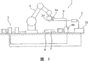
图1是作为本发明一个实施形态的自动超声波检查装置的整体结构图。Fig. 1 is an overall configuration diagram of an automatic ultrasonic inspection apparatus as an embodiment of the present invention.
图2是作为本发明一个实施形态的自动超声波检查装置的详细结构图。Fig. 2 is a detailed configuration diagram of an automatic ultrasonic inspection apparatus according to an embodiment of the present invention.
图3是作为检查对象物7的涡轮壳体73的剖面图。FIG. 3 is a cross-sectional view of a
图4是表示采用作为本发明一个实施形态的自动超声波检查装置1的动作流程的一个例子的流程图。FIG. 4 is a flow chart showing an example of the flow of operations using the automatic
图5是点焊部70的纵向剖面图和俯视图。FIG. 5 is a longitudinal sectional view and a plan view of the
图6是第3工序S3的详细流程图。FIG. 6 is a detailed flowchart of the third step S3.
图7是表示第4工序S4中的探伤点的配置的例子的配置图。FIG. 7 is a layout diagram showing an example of the layout of flaw detection points in the fourth step S4.
图8是第4工序S4的详细流程图。FIG. 8 is a detailed flowchart of the fourth step S4.
图9是表示第5工序S5中的探伤轴的设定的例子的设定图。FIG. 9 is a setting diagram showing an example of setting of flaw detection axes in the fifth step S5.
图10是第5工序S5的详细流程图。FIG. 10 is a detailed flowchart of the fifth step S5.
标号说明Label description
1自动超声波检查装置1 Automatic Ultrasonic Inspection Device
2超声波探伤器2 ultrasonic flaw detector
2a超声波探头2a ultrasonic probe
2b超声波探伤器本体2b Ultrasonic flaw detector body
4机器人手臂4 robotic arms
5控制装置5 control device
6假定中心位置确定装置6 Supposed center position determination device
6a摄像头6a camera
6b图像处理装置6b image processing device
7检查对象物7 Inspection object
8固定台8 fixed table
21探伤数据变换单元21 flaw detection data conversion unit
22第1通信单元22 1st communication unit
50机器人控制单元50 robot control unit
51固定台控制单元51 fixed table control unit
52评价值运算单元52 evaluation value operation unit
53假定中心位置运算单元53 assumed center position operation unit
54真实中心位置运算单元54 real center position computing units
55最佳评价值运算单元55 optimal evaluation value operation unit
56判定单元56 judgment units
57初始设定单元57 Initial setting unit
58第3通信单元58 3rd communication unit
59图像处理装置控制单元59 Image processing device control unit
61图像处理单元61 image processing unit
62第2通信单元62 2nd communication unit
70点焊部70 spot welds
71焊痕71 weld marks
71a外观中心位置71a Appearance center position
72熔核72 nuggets
72a内部中心位置72a interior center location
73涡轮壳体73 turbine housing
74壳体本体74 shell body
75传动平板75 transmission plate
76环状部76 Annulus
77突起部77 protrusions
具体实施方式Detailed ways
参照附图来说明本发明的一个实施形态。One embodiment of the present invention will be described with reference to the drawings.
1.自动超声波检查装置的结构1. Structure of automatic ultrasonic inspection device
图1是表示作为本发明一个实施形态的自动超声波检查装置的整体结构图,图2是表示作为本发明一个实施形态的自动超声波检查装置的详细结构图。自动超声波检查装置1是用于自动地进行检查对象物7的点焊部探伤的装置,由超声波探伤器2、机器人手臂4、假定中心位置确定装置6(假定中心位置确定单元)、固定台8以及控制装置5构成。FIG. 1 is a diagram showing the overall configuration of an automatic ultrasonic inspection device according to an embodiment of the present invention, and FIG. 2 is a diagram showing a detailed configuration of the automatic ultrasonic inspection device according to an embodiment of the present invention. The automatic
(1)超声波探伤器2(1)
超声波探伤器2是用于对点焊部进行超声波探伤的装置,由超声波探头2a和超声波探伤器本体2b构成。超声波探头2a是与点焊部接触并用于发送超声波及检测反射波的装置,安装在机器人手臂4的前端。超声波探头2a与超声波探伤器本体2b连接,能够将反射波检测信号向超声波探伤器本体2b发送。超声波探伤器本体2b是从超声波探头2a接受反射波检测信号、并将反射波检测信号变换为探伤数据的部分,与超声波探头2a连接。The
作为超声波探伤器本体2b,例如举例有安装了CPU、RAM和ROM的PC等。如图2所示,利用预先安装在超声波探伤器本体2b上的软件,来实现探伤数据变换单元21和第1通信单元22。探伤数据变换单元21具有从超声波探头2a接受反射波检测信号、并变换为探伤数据的功能。第1通信单元22具有与后述控制装置5通信的功能。这里,所谓探伤数据,是指由超声波的移动距离和反射波电平构成的数据。As the ultrasonic flaw detector
(2)机器人手臂4(2)
机器人手臂4是能够对超声波探头2a相对于点焊部的姿势和位置进行三维调整的部分。机器人手臂4具有多个关节,通过来自后述的控制装置5的机器人控制单元50的指令,能够使超声波探头2a移动到任意位置。The
(3)假定中心位置确定装置6(3) Assumed center position determining means 6
假定中心位置确定装置6是用于从点焊部的外观来确定假定中心位置的部分,由摄像头6a和图像处理装置6b构成。摄像头6a安装在机器人手臂4的前端的、不会与超声波探头2a发生干涉的位置上。另外,对摄像头6a的安装位置和角度等进行调整,使得在超声波探头2a的前端与点焊部接触时能够拍摄点焊部。The presumed center position specifying device 6 is a part for specifying the presumed center position from the appearance of the spot welding part, and is composed of a
作为图像处理装置6b,例如与超声波探伤器本体2b一样,可以举出有PC等。如图2所示,利用预先安装在图像处理装置6b上的软件,来实现图像处理单元61和第2通信单元62。图像处理单元61具有通过图像处理来确定点焊部的假定中心位置的功能。第2通信单元62具有与后述的控制装置5通信的功能。图像处理单元61的功能在后面详细描述。As the
(4)固定台8(4) Fixed table 8
固定台8是安装检查对象物7的部分,设置与检查对象物7符合的定位销。固定台8能够在水平方向上旋转和沿着水平方向移动,通过后述的控制装置5的固定台控制单元51来控制这些动作。在控制装置5中,预先设定固定台8的中心坐标和离开中心的3轴方向(X轴、Y轴、Z轴)的坐标系。因此,如果知道检查对象物7中的点焊部的位置,则能够用控制装置5预先设定点焊部离开固定台8的中心的位置坐标,并且能够使超声波探头2a向着点焊部的大致中心位置(初始中心位置)移动。The fixed table 8 is a portion on which the
在本实施形态中,作为检查对象物7,以用于力矩转换器的涡轮壳体73为例来说明。图3表示涡轮壳体73的剖面图。图3的○-○表示力矩转换器的旋转轴。涡轮壳体73由环状的壳体本体74和传送平板75构成。传送平板75由环状部76和从环状部76的内周侧向轴向突出的多个突起部77构成。因为环状部76用点焊固定在壳体本体74的外周侧表面上,所以涡轮壳体73具有多个点焊部70。本实施形态的自动超声波检测装置1对于这些点焊部70进行超声波探伤。In this embodiment, the
(5)控制装置5(5)
控制装置5是控制自动超声波检查装置1自动地进行探伤作业的装置,能够在与周边的各装置之间进行数据和信号的发送和接收。作为控制装置5,例如与上述超声波探伤器本体2b相同,可以举出有PC等。如图2所示,利用预先安装在控制装置5中的软件,从而实现机器人控制单元50、固定台控制单元51、评价值运算单元52、假定中心位置运算单元53、真实中心位置运算单元54、最佳评价值运算单元55、判定单元56、初始设定单元57、第3通信单元58和图像处理装置控制单元59。The
机器人控制单元50具有控制机器人手臂4的动作的功能。固定台控制单元51具有控制固定台8的动作的功能。评价值运算单元52具有将用超声波探伤器2取得的探伤数据变换为评价值的功能。假定中心位置运算单元53具有算出由假定中心位置确定装置6得到的假定中心位置数据的坐标的功能。The
真实中心位置运算单元54(真实中心位置确定单元)具有根据假定中心位置周边的多个评价值来确定点焊部的真实中心位置的功能。最佳评价值运算单元55具有根据在真实中心位置变换超声波探头2a的角度而得到的多个评价值、得到对于好坏判定的最佳的评价值的功能。判定单元56具有根据用最佳评价值运算单元55得到的最佳评价值来进行点焊部好坏的判定的功能。The real center position calculation unit 54 (real center position specifying unit) has a function of specifying the real center position of the spot-welded part from a plurality of evaluation values around the assumed center position. The optimum evaluation
初始设定单元57具有预先设定各运算单元等中所必需的数值的功能。第3通信单元58具有与各单元连接、并与周边设备通信的功能。图像处理装置控制单元59具有将图像处理指令发送到图像处理单元61的功能。下面详细地描述各单元的功能。The
2.自动超声波检查装置的动作流程2. Action flow of automatic ultrasonic inspection device
图4是表示采用作为本发明一个实施形态的自动超声波检查装置1的动作流程的一个例子的流程图。如图4所示,自动超声波检查装置1的动作流程主要由第1工序S1到第9工序S9来构成。FIG. 4 is a flow chart showing an example of the flow of operations using the automatic
(1)第1工序S1(1) The first process S1
在第1工序S1中,通过机器人手臂4将涡轮壳体73安装到固定台8上。这时,超声波探头2a没有安装在机器人手臂4的前端。当不是用自动超声波检查装置1的机器人手臂4、而是用相邻的设备的机器人等进行该工序时,则能够省略。In the first step S1 , the
(2)第2工序S2(2) The second process S2
在第2工序S2中,因为由于点焊部的直径不同而使得最佳超声波探头2a的直径也不同,所以机器人手臂4取出最佳超声波探头2a。这些是根据检查对象物7的种类,由控制装置5的初始设定单元57预先设定的。当相邻设备的机器人等进行第1工序S1时,只要检查对象物7的种类不改变,就能够省略该工序。In the second step S2, since the diameter of the optimal
(3)第3工序S3(假定中心位置确定工序)(3) Third step S3 (presumed center position determination step)
在第3工序S3中,根据点焊部的外观,利用假定中心指定位置6来确定假定中心位置。这里,说明点焊部的中心位置。In the third step S3, based on the appearance of the spot-welded part, the tentative center position is specified using the tentative center specifying position 6. Here, the center position of the spot weld will be described.
图5是点焊部70的纵向剖面图和俯视图。如图5所示,在点焊部70中存在着像焊痕71一样歪斜的圆形痕迹。另外,在传动平板75和环状部76之间通过点焊形成熔核72。熔核72是将传送平板75和环状部76熔接的部分。FIG. 5 is a longitudinal sectional view and a plan view of the
焊痕71和熔核72在俯视图中都具有稍微歪斜的圆形。如果将焊痕71的中心位置作为外观中心位置71a,将熔核72的中心位置作为内部中心位置72a,则一般如图5所示,两个中心位置71a和72a不一致。另一方面,为了能够正确地判定点焊部70的好坏,希望对熔核72的内部中心位置72a进行探伤。Both the
在该工序中,根据图6所示的流程,为了容易地确定内部中心位置72a,首先通过假定中心位置确定装置6从外观来确定相当于外观中心位置71a的假定中心位置。In this process, according to the flow shown in FIG. 6 , in order to easily determine the
首先,从机器人控制单元50向机器人手臂4发送指令,利用机器人手臂4使超声波探头2a向点焊部的初始中心位置移动(步骤S31)。然后,使超声波探头2a的前端与初始中心位置接触。结果,能够利用安装在机器人手臂4的前端的摄像头6a来拍摄点焊部。First, a command is sent from the
接着,从控制装置5的图像处理装置控制单元59向图像处理装置6b发送拍摄指令,利用图像处理装置61取得点焊部70的图像数据(步骤S32)。然后,对取得的图像数据进行图像处理,使得点焊部70的焊痕71的形状清楚(步骤S33)。具体地说,根据焊痕71和其周边部分的亮度或色彩的不同,利用图像处理装置6b进行图像处理,掌握焊痕71的形状,使得能够算出焊痕71的外形的坐标。Next, an imaging command is sent from the image processing device control unit 59 of the
于是,算出图像数据中的焊痕71的外周边缘的坐标(步骤ST34),根据外周边缘的坐标,算出图像数据中的假定中心位置的坐标(步骤S35)。然后,将假定中心位置数据向控制装置5发送(步骤S36)。Then, the coordinates of the outer peripheral edge of the
通过控制装置5的假定中心位置数据运算单元53,根据由初始设定单元57预先设定的图像数据中的初始中心位置和得到的假定中心位置数据,算出设置在固定台8上的坐标系中的假定中心位置的坐标数据。将算出来的假定中心位置的坐标存储在控制装置5中。By the tentative center position
如上所述,在第3工序S3中,能够得到设置在固定台8上的坐标系中的点焊部70的假定中心位置的坐标数据。As mentioned above, in the 3rd process S3, the coordinate data of the tentative center position of the
(4)第4工序S4(真实中心位置确定工序)(4) Fourth step S4 (real center position determination step)
在第4工序S4中,以由第3工序S3确定了的假定中心位置为基准,取得多个探伤数据,并确定相当于点焊部70的内部中心位置72a的真实中心位置。In the fourth step S4, a plurality of flaw detection data are obtained based on the tentative center position determined in the third step S3, and a real center position corresponding to the
这里,说明真实中心位置的确定方法。如上所述,在点焊部70的内部形成熔核72(参照图5)。该熔核72一般形成为中心最厚,在中心成为超声波衰减最多的部分。因此,为了确定熔核72的内部中心位置72a,在假定中心位置71b周边的多个位置处的超声波衰减最大的点可以认为是内部中心位置72a(正确地说是最接近内部中心位置72a的点)。在第5工序S5中,通过这样在多个探伤点进行超声波探伤,从而确定真实中心位置。Here, a method of specifying the true center position will be described. As described above, the
更具体地说明关于多个探伤点。图7表示第5工序S5中的探伤点的配置的一个例子。图7是图5所示的点焊部的俯视图的放大图。图7中为了方便起见,将假定中心位置71b与外观中心位置71a表示为同一点。如图7所示,预先设定包含点焊部70的平面和在该平面上互相垂直的P轴和Q轴。在沿着P轴和Q轴方向配置成格子状的多个探伤点An来进行超声波探伤。如果将P轴和Q轴方向的点数设定为探伤点数Np、NQ,则在本实施形态中由控制装置5来设定Np=5、NQ=5的总共25点(探伤点A1~A25)。另外,相邻的探伤点之间的P轴和Q轴方向的间隔由控制装置5预先设定作为探伤间隔δP、δQ。在这样设定了的各探伤点中,根据如图8所示的流程来进行超声波探伤。More specifically, a plurality of flaw detection points will be described. FIG. 7 shows an example of arrangement of flaw detection points in the fifth step S5. FIG. 7 is an enlarged view of a plan view of the spot welding portion shown in FIG. 5 . In FIG. 7, for the sake of convenience, the hypothetical
首先,利用机器人手臂4使超声波探头2a向探伤点A1移动,并使超声波探头2a的前端与探伤点A1接触(步骤S41)。接着,根据超声波探头2a送出的反射波检测信号,在超声波探伤器本体2b中取得探伤数据(步骤S42)。First, the
由超声波探伤器本体2b取得的探伤点A1中的探伤数据B1被取入到控制装置5中(步骤S43)。然后,利用控制装置5的评价值运算单元,根据探伤数据B1算出评价值C1(步骤S44)。在本实施形态中,使用的是根据反射回波数N和测定板厚t计算出的评价值C=2×N×t,但是也可以使用由其它方法算出的评价值。算出了的评价值C1利用控制装置5的真实中心位置运算单元与探伤点A1的坐标数据一起存入控制装置5中,作为第1探伤数据组(步骤S45)。反复进行这些步骤S41~S45,直到取得探伤点A1~A25的评价值C1~C25为止(步骤S46)。这时,设各探伤点An的超声波探头2a的角度对于包含P轴和Q轴的平面是一定的(垂直)。The flaw detection data B1 in the flaw detection point A1 acquired by the ultrasonic flaw detector
从所有的评价值C1~C25中选出最小的评价值(步骤S47)。然后,将对应于最小评价值Cn的探伤点An的坐标数据作为真实中心位置数据存入控制装置5中(步骤S48)。The smallest evaluation value is selected from all the evaluation values C 1 to C 25 (step S47). Then, the coordinate data of the flaw detection point An corresponding to the minimum evaluation value Cn is stored in the
这样,在第4工序S4中,能够得到点焊部的真实中心位置的坐标数据。Thus, in the 4th process S4, the coordinate data of the real center position of a spot welding part can be acquired.
(5)第5工序S5(最佳探伤信息取得工序)(5) Fifth process S5 (Optimum flaw detection information acquisition process)
在第5工序S5中,使超声波探头2a与由第5工序S5确定了的真实中心位置接触,改变超声波探头2a的角度,并取得多个探伤数据,从这些探伤数据中选出最适合判定点焊部好坏的探伤数据。In the fifth step S5, the
这里说明得到最佳评价值的方法。图9是表示第5工序S5中的超声波探头2a的角度设定。超声波探头2a的初始状态下的相对于点焊部的角度是与由P轴和Q轴设定了的平面垂直。以该轴位置为中心,沿着在向着P轴和Q轴方向分别改变了一定角度的多个探伤轴Dn进行探伤。P轴和Q轴方向的设定轴数为探伤轴数MP、MQ,在本实施形态中由初始设定单元57设定为MP=5、MQ=5的总共25点。另外,相邻的探伤轴Dn之间的P轴和Q轴方向的角度利用初始设定单元57预先设定为探伤角度αP、αQ。沿着这样设定了的各探伤轴Dn,如下所示地进行超声波探伤。The method for obtaining the optimum evaluation value is explained here. Fig. 9 shows the angle setting of the
如图10的流程所示,首先利用机器人手臂4使超声波探头2a向真实中心位置移动,并使超声波探头2a的前端与真实中心位置接触(步骤S51)。接着,根据超声波探头2a送出的反射波检测信号,在超声波探伤器本体2b中取得探伤数据(S52)。As shown in the flow chart of FIG. 10 , firstly, the
将由超声波探伤器本体2b取得的探伤轴D1的探伤数据库E1取入控制装置5中(步骤S53)。然后,利用控制装置5的评价值运算单元,根据探伤数据E1算出评价值F1(步骤S54)。评价值采用与第5工序S5相同的计算式算出的数据。算出了的评价值F1利用控制装置5的最佳评价值运算单元与探伤轴D1的角度数据一起存入控制装置5中,作为第2探伤数据组(步骤S55)。反复进行这些步骤S61~S65,直到取得探伤轴D1~D25的评价值F1~F25为止(步骤S56)。The flaw detection database E1 of the flaw detection axis D1 obtained from the ultrasonic flaw detector
从所有的评价值F1~F25中选出最小的评价值Fn(步骤S57)。然后,将选出的最小评价值作为最佳评价值存入控制装置5中(步骤S58)。The smallest evaluation value Fn is selected from all the evaluation values F1 to F25 (step S57). Then, the selected minimum evaluation value is stored in the
这样,在第5工序S5中,能够得到判定点焊部好坏的最佳评价值。In this way, in the fifth step S5, the optimum evaluation value for judging whether the spot weld is good or bad can be obtained.
(6)第6工序S6(判定工序)(6) Sixth step S6 (judgment step)
在第6工序S6中,将由第5工序S5得到的最佳评价值与由实验等得到的判定基准值相比较,进行判定点焊部的好坏。具体地说,当最佳评价值为判定基准值以下时,判定点焊部的焊接状态良好。当最佳评价值比判定基准值大时,判定点焊部的焊接状态不好。In the sixth step S6, the optimum evaluation value obtained in the fifth step S5 is compared with the judgment reference value obtained by experiments or the like to judge whether the spot weld is good or bad. Specifically, when the optimum evaluation value is equal to or less than the determination reference value, it is determined that the welding state of the spot weld is good. When the optimum evaluation value is larger than the determination reference value, it is determined that the welding state of the spot weld is not good.
(7)第7工序S7~第9工序S9(7) Seventh process S7 to ninth process S9
在第7工序S7中,对于1个涡轮外壳73中的多个点焊部进行从第4序S4到第6工序S6为止的探伤工序。因为在第7工序S7中对所有的点焊部进行了探伤之后,在第8工序S8中机器人手臂4使超声波探头2a返回存放部,所以取下超声波探头2a。然后,在第9工序S9中,根据第6工序S6中的判定结果,利用机器人手臂4将涡轮外壳73搬到适当的位置。In the seventh step S7, flaw detection steps from the fourth step S4 to the sixth step S6 are performed on a plurality of spot welds in one
如上所述,在超声波检查装置1中,与操作员进行的情况相比,利用假定中心位置确定装置6和控制装置5具有的各单元等,能够高速且高精度地进行点焊部好坏的判定。As described above, in the
3.作用效果3. Effect
利用与本发明相关的自动超声波检查装置1和检查方法而得到的效果总结如下。The effects obtained by using the automatic
在自动超声波检查装置1中,因为利用控制装置5的真实中心位置运算单元54,能够确定点焊部的真实中心位置、即不能从外观判断的熔核72的中心位置,所以与操作员进行探伤作业的情况相比较,能够期望点焊部70的好坏判定的高精度化和高速化。另外,因为多个探伤点An配置成格子状,所以能够更正确地确定真实中心位置。而且,由于能够利用初始设定单元57来设定P轴和Q轴方向的探伤点数NP、NQ和探伤间隔δP、δQ,所以能够对应各种大小的点焊部。In the automatic
另外,在该自动超声波检查装置1中,能够利用控制装置5的最佳评价值运算单元55从多个探伤轴Dn的第2探伤数据组选择最佳评价值。其结果,与操作员进行的情况相比较,能够得到更适合好坏判定的最佳评价值,能够期望判定点焊部好坏的高精度化。In addition, in the automatic
在该自动超声波检查装置1中,因为能够利用假定中心位置确定装置6确定从外观上判定了的假定中心位置,所以能够减小在控制装置5的真实中心位置运算单元54中取得第1探伤数据组的范围,更加能够期望判定点焊部好坏的高精度化和高速化。In this automatic
另外,通过采用如上所述的自动超声波检查装置1和检查方法来进行焊接部好坏的判定,与操作员进行的情况相比,能够期待焊接部好坏判定的高精度化和高速化,能够提高点焊产品的质量和生产率。In addition, by using the automatic
4.其他实施形态4. Other implementation forms
本发明不限定于有关的上述实施形态,在不脱离本发明范围的情况下,能够进行各种变形或者修正。下面说明其他的实施形态。The present invention is not limited to the above-mentioned embodiments, and various modifications and corrections can be made without departing from the scope of the present invention. Other embodiments will be described below.
(1)假定中心位置确定装置6(1) Supposed center position determination device 6
在上述实施形态中,是利用假定中心位置确定装置6在图像上在平面中确定焊痕71的中心,但是通过采用进行3维图像处理的图像处理软件来确定3维的假定中心位置,能够更加正确地确定假定中心位置(特别是与包含点焊部70所设定了的平面垂直的方向)。这时,摄像头6a不仅限于1台,也能够使用多台。In the above-mentioned embodiment, the center of the
另外,在上述实施形态中,所述的是利用假定中心位置确定装置6来确定假定中心位置,但是在预先设定的初始中心位置离假定中心位置相当近的情况下,或者调整探伤点数NP、NQ和探伤间隔δP、δQ的设定来扩大第5工序S5中的探伤范围的情况下,即使不使用假定中心位置确定装置6,但使用初始中心位置作为假定中心位置也可以。In addition, in the above-mentioned embodiment, it is described that the tentative center position is determined by the tentative center position determination device 6, but in the case where the preset initial center position is quite close to the tentative center position, the number of flaw detection points N P may be adjusted. , N Q and flaw detection intervals δ P , δ Q to expand the flaw detection range in the fifth step S5, the initial center position may be used as the tentative center position even if the tentative center position specifying device 6 is not used.
(2)控制装置5(2)
在上述实施形态中,超声波探伤器本体2b、控制装置5和图像处理装置6b是分别作为个别的装置,但是也可以使用安装了具有这些所有装置功能的软件的PC等。In the above-mentioned embodiment, the ultrasonic flaw detector
(3)真实中心位置运算单元54(3) True Center
在上述实施形态中,是在第4工序S4中利用真实中心位置运算单元54将多个探伤点设定为格子状,但是不仅限于此,也可以对应于点焊部的大小等来进行各种探伤点配置的设定。In the above embodiment, in the fourth step S4, a plurality of flaw detection points are set in a grid pattern by the real center
(4)最佳评价值运算单元55(4) Optimum evaluation
在上述实施形态中,是在第5工序S5中利用最佳评价值运算单元55设定多个探伤轴,但是轴的设定方法不仅限于此。例如,也可以在倾斜的状态下绕中心轴使超声波探头2a每旋转一定角度取得评价值等,根据精度和时间来进行各种探伤轴的设定。根据产品的不同,也可能减少设定轴的数量。In the above-mentioned embodiment, a plurality of flaw detection axes are set by the optimal evaluation value calculating means 55 in the fifth step S5, but the method of setting the axes is not limited to this. For example, the
工业上的实用性Industrial Applicability
在与本发明相关的自动超声波检查装置及其探伤方法中,如上所述通过进行熔核中心位置的确定和探伤评价,能够期望探伤检查的高精度化和高速化。另外,在与本发明相关的制造方法中,通过采用自动超声波探伤方法,能够力图提高点焊产品的质量和生产率。因此,与本发明相关的自动超声波检查装置、其探伤方法和制造方法适用于要求探伤检查的高精度化和高速化、以及提高点焊产品的质量和生产率的领域。In the automatic ultrasonic inspection apparatus and its flaw detection method according to the present invention, by performing determination of the nugget center position and flaw detection evaluation as described above, it is possible to expect high precision and high speed of flaw detection inspection. In addition, in the manufacturing method related to the present invention, by adopting the automatic ultrasonic flaw detection method, it is possible to try to improve the quality and productivity of spot welded products. Therefore, the automatic ultrasonic inspection device, its flaw detection method, and manufacturing method related to the present invention are suitable for fields requiring high precision and high speed of flaw detection inspection, and improvement of quality and productivity of spot welding products.
Claims (10)
Applications Claiming Priority (3)
| Application Number | Priority Date | Filing Date | Title |
|---|---|---|---|
| JP036202/2005 | 2005-02-14 | ||
| JP2005036202A JP3886014B2 (en) | 2005-02-14 | 2005-02-14 | Automatic ultrasonic inspection apparatus, inspection method thereof, and manufacturing method using the inspection method |
| PCT/JP2006/302233 WO2006085570A1 (en) | 2005-02-14 | 2006-02-09 | Automatic ultrasonic examining device, its examining method, and manufacturing method using the examining method |
Publications (2)
| Publication Number | Publication Date |
|---|---|
| CN101120248A true CN101120248A (en) | 2008-02-06 |
| CN101120248B CN101120248B (en) | 2012-07-18 |
Family
ID=36793141
Family Applications (1)
| Application Number | Title | Priority Date | Filing Date |
|---|---|---|---|
| CN2006800047976A Expired - Fee Related CN101120248B (en) | 2005-02-14 | 2006-02-09 | Automatic ultrasonic examining device, its examining method, and manufacturing method using the examining method |
Country Status (5)
| Country | Link |
|---|---|
| US (1) | US7798002B2 (en) |
| JP (1) | JP3886014B2 (en) |
| CN (1) | CN101120248B (en) |
| DE (1) | DE112006000360B4 (en) |
| WO (1) | WO2006085570A1 (en) |
Cited By (9)
| Publication number | Priority date | Publication date | Assignee | Title |
|---|---|---|---|---|
| CN102636572A (en) * | 2012-04-12 | 2012-08-15 | 中国人民解放军装甲兵工程学院 | Auxiliary device for ultrasonic detection |
| CN102809604A (en) * | 2012-07-30 | 2012-12-05 | 燕山大学 | Wall-cross type robot type ultrasonic automatic defectoscope |
| CN101846657B (en) * | 2009-03-27 | 2013-01-02 | 宝山钢铁股份有限公司 | Pipe end ultrasonic flaw detection device |
| CN110709905A (en) * | 2017-06-02 | 2020-01-17 | 株式会社日立制作所 | Automatic inspection system and control method of automatic inspection system |
| CN111066070A (en) * | 2017-09-13 | 2020-04-24 | 株式会社日立制作所 | Automatic inspection system and automatic inspection method |
| CN113490896A (en) * | 2019-02-22 | 2021-10-08 | 杰富意钢铁株式会社 | Self-propelled inspection device and inspection method for metal plate, and method for manufacturing metal plate |
| CN115266920A (en) * | 2022-06-30 | 2022-11-01 | 山东济钢型材有限公司 | Ultrasonic flaw detection equipment for straight welded pipeline weld joint and flaw detection method thereof |
| CN115635480A (en) * | 2021-07-19 | 2023-01-24 | 株式会社东芝 | Processing system, robot system, control device, processing method, control method, and storage medium |
| CN115635472A (en) * | 2021-07-19 | 2023-01-24 | 株式会社东芝 | Processing system, robot system, control device, teaching method and storage medium |
Families Citing this family (25)
| Publication number | Priority date | Publication date | Assignee | Title |
|---|---|---|---|---|
| JP5456259B2 (en) * | 2008-01-30 | 2014-03-26 | 日野自動車株式会社 | Welding inspection method and apparatus |
| US20090287427A1 (en) * | 2008-05-16 | 2009-11-19 | Lockheed Martin Corporation | Vision system and method for mapping of ultrasonic data into cad space |
| JP5267158B2 (en) * | 2009-01-27 | 2013-08-21 | トヨタ自動車株式会社 | Ultrasonic measuring device |
| US8573076B2 (en) * | 2011-07-11 | 2013-11-05 | The Boeing Company | Non-destructive inspection systems and methods that incorporate interchangeable probes |
| US9830523B2 (en) * | 2012-05-31 | 2017-11-28 | Korea Institute Of Science And Technology | Method and apparatus for recognizing object material using spatial image and spatial radar information |
| US20140207403A1 (en) * | 2013-01-22 | 2014-07-24 | General Electric Company | Inspection instrument auto-configuration |
| FR3020463B1 (en) * | 2014-04-25 | 2016-05-27 | Snecma | METHOD AND DEVICE FOR ULTRASONIC INSPECTION OF WELDINGS, ESPECIALLY AUBES WELDING ON THE DISK OF A MONOBLOC AUBING DISK |
| JP2018513976A (en) * | 2015-04-07 | 2018-05-31 | エジソン・ウェルディング・インスティチュート,インコーポレーテッド | Phased array system for inspection of laser welds |
| WO2016172078A1 (en) * | 2015-04-20 | 2016-10-27 | Edison Welding Institute, Inc. | Automated weld inspection system |
| JP6618728B2 (en) | 2015-07-09 | 2019-12-11 | Ntn株式会社 | Method for manufacturing outer joint member of constant velocity universal joint and ultrasonic flaw detection inspection method for welded part |
| DE102016110164A1 (en) | 2016-06-02 | 2017-12-07 | Dr. Ing. H.C. F. Porsche Aktiengesellschaft | Connecting device for connecting a robot device with an ultrasonic measuring device |
| CN107688053A (en) * | 2017-09-25 | 2018-02-13 | 三峡大学 | A kind of spot welding ultrasound B sweeps automatic detection device and method |
| DE102017125033A1 (en) * | 2017-10-25 | 2019-04-25 | ese-robotics GmbH | Processes and industrial robots for testing welded joints, in particular spot welds |
| JP6570600B2 (en) * | 2017-11-15 | 2019-09-04 | 株式会社東芝 | Inspection system, control device, angle adjustment method, program, and storage medium |
| KR101995418B1 (en) * | 2018-12-04 | 2019-07-02 | 주식회사 신영 | Automatic system for nondestructive inspection of weld zone |
| DE102019104654A1 (en) * | 2019-02-25 | 2020-08-27 | Battenberg Robotic Gmbh & Co. Kg | Procedure for checking a weld |
| MX2020002026A (en) * | 2019-02-25 | 2020-08-26 | Battenberg Robotic Gmbh & Co Kg | Method for testing of a weld, and ultrasonic probe arrangement. |
| DE202020100206U1 (en) * | 2020-01-16 | 2021-04-19 | Battenberg Robotic Gmbh & Co. Kg | Ultrasonic probe assembly |
| EP3969893B1 (en) * | 2019-05-13 | 2025-11-05 | ABB Schweiz AG | Non-destructive inspection of test objects on a workpiece |
| JP7214589B2 (en) * | 2019-07-30 | 2023-01-30 | 株式会社東芝 | Inspection system, angle adjustment method, program, and storage medium |
| US11561204B2 (en) | 2019-08-28 | 2023-01-24 | Kabushiki Kaisha Toshiba | Display control system, inspection control system, display control method, and storage medium |
| EP3798629B1 (en) | 2019-09-24 | 2024-10-23 | Kabushiki Kaisha Toshiba | Processing system, processing method, and storage medium |
| DE102020209587A1 (en) | 2020-07-30 | 2022-02-03 | Volkswagen Aktiengesellschaft | Device for ultrasonic testing of welds |
| JP7722857B2 (en) * | 2021-07-19 | 2025-08-13 | 株式会社東芝 | Data processing device, data processing system, data processing method, program, and storage medium |
| US20250255579A1 (en) * | 2024-02-08 | 2025-08-14 | Fujifilm Sonosite, Inc. | Repeatable Ultrasound |
Family Cites Families (18)
| Publication number | Priority date | Publication date | Assignee | Title |
|---|---|---|---|---|
| US4368644A (en) * | 1981-05-26 | 1983-01-18 | Combustion Engineering, Inc. | Tool for inspecting defects in irregular weld bodies |
| JPS6148360U (en) * | 1984-08-31 | 1986-04-01 | ||
| JPS63148864U (en) * | 1987-03-20 | 1988-09-30 | ||
| WO1991002971A1 (en) * | 1989-08-21 | 1991-03-07 | Hitachi Construction Machinery Co., Ltd. | Ultrasonic flaw detector |
| DE4109625A1 (en) * | 1991-03-23 | 1992-09-24 | Krautkraemer Gmbh | ULTRASONIC MEASUREMENT METHOD FOR THE WALL THICKNESS DEVELOPMENT OF A WELDED SEAM OF A PIPE |
| JPH05288724A (en) * | 1992-04-08 | 1993-11-02 | Asupekuto:Kk | Automatic ultrasonic flaw detection |
| JPH06265529A (en) | 1993-03-15 | 1994-09-22 | Hitachi Ltd | Method and apparatus for evaluating spot-welded part |
| JPH08110332A (en) | 1994-10-11 | 1996-04-30 | Komatsu Ltd | Ultrasonic inspection method by articulated robot and its apparatus |
| US5773721A (en) * | 1996-07-31 | 1998-06-30 | General Electric Company | Laser beam aiming apparatus for ultrasonic inspection |
| GB9803364D0 (en) * | 1998-02-18 | 1998-04-15 | Armstrong Healthcare Ltd | Improvements in or relating to a method of an apparatus for registering a robot |
| JPH11326287A (en) | 1998-05-15 | 1999-11-26 | Nippon Krautkraemer Ferusutaa Kk | Judging method of molten solidified part of welded part using ultrasonic flaw detector |
| JP3712254B2 (en) * | 2000-09-22 | 2005-11-02 | 山陽特殊製鋼株式会社 | Estimation method of defect diameter in metal materials |
| DE10125782B4 (en) * | 2000-10-25 | 2004-12-23 | SCHWEIßTECHNISCHE LEHR- UND VERSUCHSANSTALT HALLE GMBH | Process for the automated ultrasonic testing of resistance spot welds |
| DE10113238C1 (en) * | 2001-03-19 | 2002-09-12 | Amatec Robotics Gmbh | Process for testing welding sites in car chassis parts uses a robot with an ultrasound testing probe in its arm |
| JP2006153710A (en) | 2004-11-30 | 2006-06-15 | Daihen Corp | Welding inspection probe and welding inspection system using the same |
| DE102005043699A1 (en) * | 2005-09-14 | 2007-03-22 | Daimlerchrysler Ag | Ultrasonic test head positioning procedure uses camera fixed on industrial robot to image approximate weld position to create data to place test head in ideal position |
| DE102005043776A1 (en) * | 2005-09-14 | 2007-03-22 | Bayerische Motoren Werke Ag | Ultrasonic test head positioning procedure uses camera fixed on industrial robot to image approximate weld position to create data to place test head in ideal position |
| US7448272B2 (en) * | 2005-12-22 | 2008-11-11 | Ford Global Technologies, Llc | System and method for inspecting spot weld |
-
2005
- 2005-02-14 JP JP2005036202A patent/JP3886014B2/en not_active Expired - Fee Related
-
2006
- 2006-02-09 WO PCT/JP2006/302233 patent/WO2006085570A1/en not_active Ceased
- 2006-02-09 US US11/884,197 patent/US7798002B2/en not_active Expired - Fee Related
- 2006-02-09 DE DE112006000360T patent/DE112006000360B4/en not_active Expired - Fee Related
- 2006-02-09 CN CN2006800047976A patent/CN101120248B/en not_active Expired - Fee Related
Cited By (15)
| Publication number | Priority date | Publication date | Assignee | Title |
|---|---|---|---|---|
| CN101846657B (en) * | 2009-03-27 | 2013-01-02 | 宝山钢铁股份有限公司 | Pipe end ultrasonic flaw detection device |
| CN102636572A (en) * | 2012-04-12 | 2012-08-15 | 中国人民解放军装甲兵工程学院 | Auxiliary device for ultrasonic detection |
| CN102636572B (en) * | 2012-04-12 | 2014-12-10 | 中国人民解放军装甲兵工程学院 | Auxiliary device for ultrasonic detection |
| CN102809604A (en) * | 2012-07-30 | 2012-12-05 | 燕山大学 | Wall-cross type robot type ultrasonic automatic defectoscope |
| CN102809604B (en) * | 2012-07-30 | 2014-11-12 | 燕山大学 | Wall-cross type robot type ultrasonic automatic defectoscope |
| CN110709905A (en) * | 2017-06-02 | 2020-01-17 | 株式会社日立制作所 | Automatic inspection system and control method of automatic inspection system |
| CN111066070A (en) * | 2017-09-13 | 2020-04-24 | 株式会社日立制作所 | Automatic inspection system and automatic inspection method |
| CN113490896A (en) * | 2019-02-22 | 2021-10-08 | 杰富意钢铁株式会社 | Self-propelled inspection device and inspection method for metal plate, and method for manufacturing metal plate |
| US12050453B2 (en) | 2019-02-22 | 2024-07-30 | Jfe Steel Corporation | Autonomous metal-plate inspection apparatus, inspection method, and method for manufacturing metal plate |
| CN115635480A (en) * | 2021-07-19 | 2023-01-24 | 株式会社东芝 | Processing system, robot system, control device, processing method, control method, and storage medium |
| CN115635472A (en) * | 2021-07-19 | 2023-01-24 | 株式会社东芝 | Processing system, robot system, control device, teaching method and storage medium |
| US12318921B2 (en) | 2021-07-19 | 2025-06-03 | Kabushiki Kaisha Toshiba | Processing system, robot system, control device, processing method, control method, and storage medium |
| CN115635480B (en) * | 2021-07-19 | 2025-11-21 | 株式会社东芝 | Processing system, robot system, control device, processing method, control method, and storage medium |
| US12569939B2 (en) | 2021-07-19 | 2026-03-10 | Kabushiki Kaisha Toshiba | Processing system, robot system, control device, teaching method, and storage medium |
| CN115266920A (en) * | 2022-06-30 | 2022-11-01 | 山东济钢型材有限公司 | Ultrasonic flaw detection equipment for straight welded pipeline weld joint and flaw detection method thereof |
Also Published As
| Publication number | Publication date |
|---|---|
| US20080210009A1 (en) | 2008-09-04 |
| JP3886014B2 (en) | 2007-02-28 |
| DE112006000360T5 (en) | 2007-12-27 |
| DE112006000360B4 (en) | 2012-12-13 |
| WO2006085570A1 (en) | 2006-08-17 |
| JP2006220608A (en) | 2006-08-24 |
| US7798002B2 (en) | 2010-09-21 |
| CN101120248B (en) | 2012-07-18 |
Similar Documents
| Publication | Publication Date | Title |
|---|---|---|
| CN101120248B (en) | Automatic ultrasonic examining device, its examining method, and manufacturing method using the examining method | |
| US9759691B2 (en) | Gating methods for use in weld inspection systems | |
| CN114714029B (en) | Automatic arc welding method and device for aluminum alloy | |
| CN104985289B (en) | Laser sensor-based welding seam automatic tracking test device and test method thereof | |
| US8725285B2 (en) | Robot system and transfer method | |
| CN106841398B (en) | The positioning supersonic detection device and method of curved surface weldment | |
| US11656205B2 (en) | Method for testing of a weld, and ultrasonic probe arrangement | |
| CN110906863B (en) | Hand-eye calibration system and calibration method for line-structured light sensor | |
| CN110057914B (en) | Automatic non-destructive testing device and method for composite curved surface structure | |
| JP4111902B2 (en) | Automatic inspection system | |
| JP4837425B2 (en) | Inspection method and apparatus for spot welds | |
| JP2021522520A (en) | Robot systems and methods for non-destructive inspection | |
| JP2021058985A (en) | Robot, measuring jig, and method of deciding tool tip end position | |
| Mineo et al. | Robotic path planning for non-destructive testing of complex shaped surfaces | |
| JP2019000923A (en) | Method for estimating mechanism model parameter of articulated robot | |
| US12181444B2 (en) | Method for detecting position anomaly of test object, control system, testing system, robot system, testing robot, and programming device | |
| JP5113623B2 (en) | Robot controller that teaches robot position using a measuring device | |
| CN108896658A (en) | A kind of ultrasonic wave automated detection method based on PLC | |
| CN117415826B (en) | Control method and device of detection system and readable storage medium | |
| JP3195850B2 (en) | Method and apparatus for measuring three-dimensional position on curved surface | |
| JPH02243914A (en) | Three-dimensional coordinate measuring instrument | |
| CN118641629B (en) | A method for weld defect detection based on robot-mounted vision | |
| WO2021186981A1 (en) | Control device, inspection system, control method, program, and storage medium | |
| CN119187820B (en) | Positioning, picking and placing method and system for mechanical arm for ultrasonic welding of drug feeder | |
| Zhang et al. | A two-step point cloud registration for multi-station automated ultrasonic inspection systems |
Legal Events
| Date | Code | Title | Description |
|---|---|---|---|
| C06 | Publication | ||
| PB01 | Publication | ||
| C10 | Entry into substantive examination | ||
| SE01 | Entry into force of request for substantive examination | ||
| C14 | Grant of patent or utility model | ||
| GR01 | Patent grant | ||
| C17 | Cessation of patent right | ||
| CF01 | Termination of patent right due to non-payment of annual fee |
Granted publication date: 20120718 Termination date: 20140209 |