DE102023108134A1 - CONNECTORS, CONNECTOR SYSTEMS AND TRANSMISSION METHODS - Google Patents
CONNECTORS, CONNECTOR SYSTEMS AND TRANSMISSION METHODS Download PDFInfo
- Publication number
- DE102023108134A1 DE102023108134A1 DE102023108134.9A DE102023108134A DE102023108134A1 DE 102023108134 A1 DE102023108134 A1 DE 102023108134A1 DE 102023108134 A DE102023108134 A DE 102023108134A DE 102023108134 A1 DE102023108134 A1 DE 102023108134A1
- Authority
- DE
- Germany
- Prior art keywords
- connector
- conductor contacts
- transmission
- shield
- outer conductor
- Prior art date
- Legal status (The legal status is an assumption and is not a legal conclusion. Google has not performed a legal analysis and makes no representation as to the accuracy of the status listed.)
- Pending
Links
- 230000005540 biological transmission Effects 0.000 title claims abstract description 39
- 238000000034 method Methods 0.000 title claims abstract description 13
- 239000004020 conductor Substances 0.000 claims abstract description 83
- 239000012212 insulator Substances 0.000 claims abstract description 11
- 230000013011 mating Effects 0.000 claims description 11
- 230000002457 bidirectional effect Effects 0.000 claims description 8
- 230000000295 complement effect Effects 0.000 claims description 4
- 230000005855 radiation Effects 0.000 description 8
- 230000008054 signal transmission Effects 0.000 description 3
- 238000009413 insulation Methods 0.000 description 2
- 238000002955 isolation Methods 0.000 description 2
- 238000000926 separation method Methods 0.000 description 2
- BUHVIAUBTBOHAG-FOYDDCNASA-N (2r,3r,4s,5r)-2-[6-[[2-(3,5-dimethoxyphenyl)-2-(2-methylphenyl)ethyl]amino]purin-9-yl]-5-(hydroxymethyl)oxolane-3,4-diol Chemical compound COC1=CC(OC)=CC(C(CNC=2C=3N=CN(C=3N=CN=2)[C@H]2[C@@H]([C@H](O)[C@@H](CO)O2)O)C=2C(=CC=CC=2)C)=C1 BUHVIAUBTBOHAG-FOYDDCNASA-N 0.000 description 1
- 238000004891 communication Methods 0.000 description 1
- 230000000694 effects Effects 0.000 description 1
- 230000005288 electromagnetic effect Effects 0.000 description 1
- 238000005516 engineering process Methods 0.000 description 1
- 238000004519 manufacturing process Methods 0.000 description 1
- 239000012811 non-conductive material Substances 0.000 description 1
- 238000005476 soldering Methods 0.000 description 1
Images


Classifications
-
- H—ELECTRICITY
- H01—ELECTRIC ELEMENTS
- H01R—ELECTRICALLY-CONDUCTIVE CONNECTIONS; STRUCTURAL ASSOCIATIONS OF A PLURALITY OF MUTUALLY-INSULATED ELECTRICAL CONNECTING ELEMENTS; COUPLING DEVICES; CURRENT COLLECTORS
- H01R13/00—Details of coupling devices of the kinds covered by groups H01R12/70 or H01R24/00 - H01R33/00
- H01R13/648—Protective earth or shield arrangements on coupling devices, e.g. anti-static shielding
- H01R13/658—High frequency shielding arrangements, e.g. against EMI [Electro-Magnetic Interference] or EMP [Electro-Magnetic Pulse]
- H01R13/6591—Specific features or arrangements of connection of shield to conductive members
- H01R13/6592—Specific features or arrangements of connection of shield to conductive members the conductive member being a shielded cable
- H01R13/6593—Specific features or arrangements of connection of shield to conductive members the conductive member being a shielded cable the shield being composed of different pieces
-
- H—ELECTRICITY
- H01—ELECTRIC ELEMENTS
- H01R—ELECTRICALLY-CONDUCTIVE CONNECTIONS; STRUCTURAL ASSOCIATIONS OF A PLURALITY OF MUTUALLY-INSULATED ELECTRICAL CONNECTING ELEMENTS; COUPLING DEVICES; CURRENT COLLECTORS
- H01R13/00—Details of coupling devices of the kinds covered by groups H01R12/70 or H01R24/00 - H01R33/00
- H01R13/648—Protective earth or shield arrangements on coupling devices, e.g. anti-static shielding
- H01R13/658—High frequency shielding arrangements, e.g. against EMI [Electro-Magnetic Interference] or EMP [Electro-Magnetic Pulse]
- H01R13/6591—Specific features or arrangements of connection of shield to conductive members
- H01R13/6594—Specific features or arrangements of connection of shield to conductive members the shield being mounted on a PCB and connected to conductive members
-
- H—ELECTRICITY
- H01—ELECTRIC ELEMENTS
- H01R—ELECTRICALLY-CONDUCTIVE CONNECTIONS; STRUCTURAL ASSOCIATIONS OF A PLURALITY OF MUTUALLY-INSULATED ELECTRICAL CONNECTING ELEMENTS; COUPLING DEVICES; CURRENT COLLECTORS
- H01R13/00—Details of coupling devices of the kinds covered by groups H01R12/70 or H01R24/00 - H01R33/00
- H01R13/02—Contact members
-
- H—ELECTRICITY
- H01—ELECTRIC ELEMENTS
- H01R—ELECTRICALLY-CONDUCTIVE CONNECTIONS; STRUCTURAL ASSOCIATIONS OF A PLURALITY OF MUTUALLY-INSULATED ELECTRICAL CONNECTING ELEMENTS; COUPLING DEVICES; CURRENT COLLECTORS
- H01R13/00—Details of coupling devices of the kinds covered by groups H01R12/70 or H01R24/00 - H01R33/00
- H01R13/46—Bases; Cases
- H01R13/502—Bases; Cases composed of different pieces
-
- H—ELECTRICITY
- H01—ELECTRIC ELEMENTS
- H01R—ELECTRICALLY-CONDUCTIVE CONNECTIONS; STRUCTURAL ASSOCIATIONS OF A PLURALITY OF MUTUALLY-INSULATED ELECTRICAL CONNECTING ELEMENTS; COUPLING DEVICES; CURRENT COLLECTORS
- H01R13/00—Details of coupling devices of the kinds covered by groups H01R12/70 or H01R24/00 - H01R33/00
- H01R13/646—Details of coupling devices of the kinds covered by groups H01R12/70 or H01R24/00 - H01R33/00 specially adapted for high-frequency, e.g. structures providing an impedance match or phase match
-
- H—ELECTRICITY
- H01—ELECTRIC ELEMENTS
- H01R—ELECTRICALLY-CONDUCTIVE CONNECTIONS; STRUCTURAL ASSOCIATIONS OF A PLURALITY OF MUTUALLY-INSULATED ELECTRICAL CONNECTING ELEMENTS; COUPLING DEVICES; CURRENT COLLECTORS
- H01R13/00—Details of coupling devices of the kinds covered by groups H01R12/70 or H01R24/00 - H01R33/00
- H01R13/648—Protective earth or shield arrangements on coupling devices, e.g. anti-static shielding
- H01R13/658—High frequency shielding arrangements, e.g. against EMI [Electro-Magnetic Interference] or EMP [Electro-Magnetic Pulse]
- H01R13/6581—Shield structure
-
- H—ELECTRICITY
- H01—ELECTRIC ELEMENTS
- H01R—ELECTRICALLY-CONDUCTIVE CONNECTIONS; STRUCTURAL ASSOCIATIONS OF A PLURALITY OF MUTUALLY-INSULATED ELECTRICAL CONNECTING ELEMENTS; COUPLING DEVICES; CURRENT COLLECTORS
- H01R24/00—Two-part coupling devices, or either of their cooperating parts, characterised by their overall structure
- H01R24/38—Two-part coupling devices, or either of their cooperating parts, characterised by their overall structure having concentrically or coaxially arranged contacts
- H01R24/40—Two-part coupling devices, or either of their cooperating parts, characterised by their overall structure having concentrically or coaxially arranged contacts specially adapted for high frequency
- H01R24/50—Two-part coupling devices, or either of their cooperating parts, characterised by their overall structure having concentrically or coaxially arranged contacts specially adapted for high frequency mounted on a PCB [Printed Circuit Board]
-
- H—ELECTRICITY
- H01—ELECTRIC ELEMENTS
- H01R—ELECTRICALLY-CONDUCTIVE CONNECTIONS; STRUCTURAL ASSOCIATIONS OF A PLURALITY OF MUTUALLY-INSULATED ELECTRICAL CONNECTING ELEMENTS; COUPLING DEVICES; CURRENT COLLECTORS
- H01R9/00—Structural associations of a plurality of mutually-insulated electrical connecting elements, e.g. terminal strips or terminal blocks; Terminals or binding posts mounted upon a base or in a case; Bases therefor
- H01R9/03—Connectors arranged to contact a plurality of the conductors of a multiconductor cable, e.g. tapping connections
- H01R9/05—Connectors arranged to contact a plurality of the conductors of a multiconductor cable, e.g. tapping connections for coaxial cables
- H01R9/0503—Connection between two cable ends
-
- H—ELECTRICITY
- H01—ELECTRIC ELEMENTS
- H01R—ELECTRICALLY-CONDUCTIVE CONNECTIONS; STRUCTURAL ASSOCIATIONS OF A PLURALITY OF MUTUALLY-INSULATED ELECTRICAL CONNECTING ELEMENTS; COUPLING DEVICES; CURRENT COLLECTORS
- H01R9/00—Structural associations of a plurality of mutually-insulated electrical connecting elements, e.g. terminal strips or terminal blocks; Terminals or binding posts mounted upon a base or in a case; Bases therefor
- H01R9/03—Connectors arranged to contact a plurality of the conductors of a multiconductor cable, e.g. tapping connections
- H01R9/05—Connectors arranged to contact a plurality of the conductors of a multiconductor cable, e.g. tapping connections for coaxial cables
- H01R9/0515—Connection to a rigid planar substrate, e.g. printed circuit board
-
- H—ELECTRICITY
- H04—ELECTRIC COMMUNICATION TECHNIQUE
- H04L—TRANSMISSION OF DIGITAL INFORMATION, e.g. TELEGRAPHIC COMMUNICATION
- H04L12/00—Data switching networks
- H04L12/02—Details
- H04L12/10—Current supply arrangements
-
- H—ELECTRICITY
- H01—ELECTRIC ELEMENTS
- H01R—ELECTRICALLY-CONDUCTIVE CONNECTIONS; STRUCTURAL ASSOCIATIONS OF A PLURALITY OF MUTUALLY-INSULATED ELECTRICAL CONNECTING ELEMENTS; COUPLING DEVICES; CURRENT COLLECTORS
- H01R2103/00—Two poles
Landscapes
- Engineering & Computer Science (AREA)
- Computer Networks & Wireless Communication (AREA)
- Signal Processing (AREA)
- Details Of Connecting Devices For Male And Female Coupling (AREA)
Abstract
Die vorliegende Erfindung betrifft einen Steckverbinder (1) aufweisend zumindest zwei separate Innenleiterkontakte (2), zumindest zwei separate Außenleiterkontakte (6), die jeweils einen Innenleiterkontakt (2) umgeben und jeweils durch einen Isolator (4) von dem jeweiligen Innenleiterkontakt (2) isoliert sind, eine Halterung (8) zum Halten der zumindest zwei Außenleiterkontakte (6), ein Schirmgehäuse (10), in dem die Halterung (8), die Außenleiterkontakte (6), die Isolatoren (4) und die Innenleiterkontakte (2) im montierten Zustand angeordnet sind, wobei das Schirmgehäuse (10) die Außenleiterkontakte (6) entlang ihrer Leitungsrichtung (LR) vollständig umgibt und als Abschirmung dient. Die Erfindung betrifft weiterhin ein Steckverbindersystem und ein Übertragungsverfahren.The present invention relates to a plug connector (1) having at least two separate inner conductor contacts (2), at least two separate outer conductor contacts (6), each of which surrounds an inner conductor contact (2) and is each insulated from the respective inner conductor contact (2) by an insulator (4), a holder (8) for holding the at least two outer conductor contacts (6), a shield housing (10) in which the holder (8), the outer conductor contacts (6), the insulators (4) and the inner conductor contacts (2) are arranged in the assembled state, wherein the shield housing (10) completely surrounds the outer conductor contacts (6) along their conduction direction (LR) and serves as a shield. The invention further relates to a plug connector system and a transmission method.
Description
Technisches Gebiettechnical field
Die Erfindung betrifft einen Steckverbinder, insbesondere für eine koaxiale Steckverbindung, ein Steckverbindersystem sowie ein Übertragungsverfahren, die bevorzugt alle für eine Power-over-Coax Verbindung oder Übertragung geeignet sind.The invention relates to a connector, in particular for a coaxial connector, a connector system and a transmission method, all of which are preferably suitable for a power-over-coax connection or transmission.
Stand der TechnikState of the art
Steckverbinder für koaxiale Steckverbindungen aus dem Stand der Technik sind bis maximal 15 GHz Übertragungsfrequenz ausgelegt. Die Signalübertragung ist mit 6 Gbit/s bis 12 Gbit/s möglich. Diese Werte sollen für zukünftige Anwendungen gesteigert werden.State-of-the-art connectors for coaxial connections are designed for a maximum transmission frequency of 15 GHz. Signal transmission is possible at 6 Gbit/s to 12 Gbit/s. These values are to be increased for future applications.
Weiterhin bezeichnet Power-over-Coax (PoC) die Stromversorgung eines Verbrauchers über eine angeschlossene koaxiale Steckverbindung. PoC kann jedoch zu Problemen mit der Elektromagnetischen Verträglichkeit (EMV) führen, d.h. der Verbraucher kann andere Geräte stören oder von ihnen gestört werden. Diese EMV Probleme können auftreten, da im Fall von PoC der Außenleiter als Stromleiter fungiert, und nicht zur Abschirmung dienen kann. Bei PoC erfolgt eine Aufspaltung von Daten und Leistung über die Frequenz, der Strom wird über den Innen- und Außenleiter übertragen. Eine koaxiale Steckverbindung aus zumindest zwei Koaxialleitungen kann in Stand der Technik entweder als differentielle Koaxialverbindung oder als Shielded Twisted Pair (STP) Verbindung verwendet werden, jedoch niemals als beides.Power-over-Coax (PoC) also refers to the power supply of a consumer via a connected coaxial connector. However, PoC can lead to problems with electromagnetic compatibility (EMC), i.e. the consumer can interfere with other devices or be interfered with by them. These EMC problems can occur because in the case of PoC the outer conductor acts as a current conductor and cannot be used for shielding. With PoC, data and power are split across the frequency, and the current is transmitted via the inner and outer conductors. In the state of the art, a coaxial connector made up of at least two coaxial cables can be used either as a differential coaxial connection or as a shielded twisted pair (STP) connection, but never as both.
Die Druckschrift
Zusammengefasst ergeben sich im Stand der Technik die Probleme, dass sich HF Verbindungen über 15 GHz nicht realisieren lassen. Der Einsatz von PoC ist aufgrund der EMV Probleme nicht praktikabel. Denn der Außenleiter einer koaxialen Steckverbindung wird als Stromleiter (Minus-Pol) eingesetzt, wodurch sich elektromagnetische Effekte ergeben, die zur erhöhten Abstrahlung (entspricht dem EMV Problem) führen können. Insbesondere in sicherheitskritischen Systemen, wie im Automotive Bereich, müssen EMV Probleme ausgeschlossen werden. Darüber hinaus kommt es bei PoC zu einem Spannungsabfall bei höheren Strömen über die Leitung. Und schließlich erfordert jede eingesetzte Verbindungstechnik (STP oder koaxial) einen separaten Steckertypus.In summary, the current state of the art has the problem that HF connections above 15 GHz cannot be implemented. The use of PoC is not practical due to EMC problems. The outer conductor of a coaxial connector is used as a current conductor (negative pole), which results in electromagnetic effects that can lead to increased radiation (corresponds to the EMC problem). EMC problems must be ruled out, particularly in safety-critical systems such as in the automotive sector. In addition, PoC results in a voltage drop at higher currents over the cable. And finally, each connection technology used (STP or coaxial) requires a separate connector type.
Beschreibung der ErfindungDescription of the Invention
Es ist daher eine Aufgabe der vorliegenden Erfindung Übertragungsmöglichkeiten bereitzustellen, die höhere Frequenzen und Datenübertragungsraten ermöglichen, universell einsetzbar sind und ein Auftreten von EMV Problemen verhindern.It is therefore an object of the present invention to provide transmission options that enable higher frequencies and data transmission rates, are universally applicable and prevent the occurrence of EMC problems.
Die oben genannte Aufgabe wird durch einen Steckverbinder nach Anspruch 1, ein Steckverbindersystem nach Anspruch 5 sowie ein Übertragungsverfahren nach Anspruch 6 gelöst. Weitere vorteilhafte Ausgestaltungsformen der Erfindung lassen sich den Unteransprüchen, der Beschreibung sowie den Zeichnungen entnehmen.The above-mentioned object is achieved by a connector according to
Insbesondere wird die oben genannte Aufgabe gelöst durch einen Steckverbinder aufweisend zumindest zwei separate Innenleiterkontakte, zumindest zwei separate Außenleiterkontakte, die jeweils einen Innenleiterkontakt umgeben und jeweils durch einen Isolator von dem jeweiligen Innenleiterkontakt isoliert sind, eine Halterung zum Halten der zumindest zwei Außenleiterkontakte, ein Schirmgehäuse, in dem die Halterung, die Außenleiterkontakte, die Isolatoren und die Innenleiterkontakte im montierten Zustand angeordnet sind, wobei das Schirmgehäuse die Außenleiterkontakte entlang ihrer Leitungsrichtung vollständig umgibt und als Abschirmung dient.In particular, the above-mentioned object is achieved by a connector having at least two separate inner conductor contacts, at least two separate outer conductor contacts, each of which surrounds an inner conductor contact and is each insulated from the respective inner conductor contact by an insulator, a holder for holding the at least two outer conductor contacts, a shield housing in which the holder, the outer conductor contacts, the insulators and the inner conductor contacts are arranged in the assembled state, wherein the shield housing completely surrounds the outer conductor contacts along their conduction direction and serves as a shield.
Der Steckverbinder ist insbesondere eingerichtet für eine Power-over-Coax Verbindung mittels zumindest zwei geschirmter Leitungen. Der Steckverbinder ist bevorzugt ein Automotive Steckverbinder, der an eine PCB und/oder Kabelseite angebracht werden kann. Durch den Steckverbinder kann eine Verbindung mit einem bis N koaxialen Leitern und einem zusätzlichen Außenschirm, der über alle 1 bis N koaxialen Leitern wirkt, aufgebaut werden. Dieser zusätzliche Außenschirm bietet eine Verbesserung der Schirmwirkung und ermöglicht PoC ohne erhöhte EMV Abstrahlung. Insbesondere bei stoßartigem Stromverbrauch können ungewollte Spitzen auftreten, die zu einer erhöhten EMV Abstrahlung führen. Durch den vorliegenden (zusätzlichen) Außenschirm wird diese erhöhte EMV Abstrahlung abgefangen. Bei einer zweifachen Koaxialleitung kann die Verwendung beider koaxialen Leiter für die Versorgung die max. Strombelastung verdoppeln bzw. den Spannungsabfall halbieren. Der Steckverbinder bildet dabei ein universelles Stecksystem für Koax, „differentielles Koax“ und differentielle Leitungen. Durch die doppelt geschirmten koaxialen Leiter kann eine Steigerung der Übertragungsraten erreicht werden.The connector is particularly designed for a power-over-coax connection using at least two shielded cables. The connector is preferably an automotive connector that can be attached to a PCB and/or cable side. The connector can be used to establish a connection with one to N coaxial conductors and an additional outer shield that acts across all 1 to N coaxial conductors. This additional outer shield improves the shielding effect and enables PoC without increased EMC radiation. In particular, with sudden power consumption, unwanted peaks can occur that lead to increased EMC radiation. The present (additional This increased EMC radiation is intercepted by the double-shielded outer shield. With a double coaxial cable, using both coaxial conductors for the supply can double the maximum current load or halve the voltage drop. The connector forms a universal plug system for coax, "differential coax" and differential cables. The double-shielded coaxial conductors can increase the transmission rates.
Die Leitungsrichtung ist die Richtung entlang welcher Signale und/oder Strom über die Außenleiter geleitet werden. Die Leitungsrichtung kann zum Beispiel im Fall von gewinkelten Außenleitern auch nicht-linear, genauer gesagt gewinkelt, sein.The conduction direction is the direction along which signals and/or current are conducted via the outer conductors. The conduction direction can also be non-linear, or more precisely angled, for example in the case of angled outer conductors.
Bevorzugt weist das Schirmgehäuse eine Abschirmung auf, die einen Kontaktierungsbereich der Außenleiterkontakte umgibt. Die Abschirmung ist elektrisch leitfähig, und bevorzugt fest mit dem Schirmgehäuse verbunden oder einteilig mit dem Schirmgehäuse ausgebildet. Durch die Abschirmung sind die Steckverbinder-seitigen Außenleiterkontakte vollständig abgeschirmt. Gegenüber dem Stand der Technik ist also auch der Kontaktierungsbereich zwischen Steckverbinder und Gegensteckverbinder im gesteckten Zustand (zusätzlich) abgeschirmt und verbessert damit die Signalübertragung. Das die Abschirmung den Kontaktierungsbereich der Außenleiterkontakte umgibt heißt, dass die Außenleiterkontakte im Kontaktierungsbereich entlang einer Steckrichtung umfänglich von der Abschirmung umgeben sind, wobei ein Stecken von Steckerverbinder und Gegensteckverbinder ungehindert möglich ist.The shield housing preferably has a shield that surrounds a contact area of the outer conductor contacts. The shield is electrically conductive and is preferably firmly connected to the shield housing or formed as one piece with the shield housing. The shield completely shields the outer conductor contacts on the connector side. Compared to the prior art, the contact area between the connector and the mating connector is also (additionally) shielded when plugged in, thus improving signal transmission. The fact that the shield surrounds the contact area of the outer conductor contacts means that the outer conductor contacts in the contact area are surrounded by the shield along one plugging direction, whereby plugging in the connector and the mating connector is possible without hindrance.
Bevorzugt sind das Schirmgehäuse, die Außenleiterkontakte sowie die Innenleiterkontakte voneinander galvanisch getrennt. Durch die galvanische Isolation kann eine Versorgungsspannung je Kanal realisiert werden. Bei zwei Kanälen können so zwei Spannungen aufgebracht bzw. verwendet werden.Preferably, the shield housing, the outer conductor contacts and the inner conductor contacts are galvanically isolated from each other. The galvanic isolation allows one supply voltage to be implemented per channel. With two channels, two voltages can be applied or used.
Bevorzugt beabstandet die Halterung die Außenleiterkontakte, und isoliert sie untereinander sowie gegenüber dem Schirmgehäuse. Die Isolation oder Trennung umfasst dabei sowohl eine räumliche als auch eine elektrische Trennung.Preferably, the holder spaced the outer conductor contacts apart and insulated them from each other and from the shield housing. The insulation or separation includes both spatial and electrical separation.
Die oben genannte Aufgabe wird weiterhin insbesondere gelöst durch ein Steckverbindersystem aufweisend einen Steckverbinder und einen komplementären Gegensteckverbinder.The above-mentioned object is further achieved in particular by a connector system comprising a connector and a complementary mating connector.
Die oben genannte Aufgabe wird weiterhin insbesondere gelöst durch ein Übertragungsverfahren, insbesondere für eine Power-over-Coax Übertragung, mittels zumindest zwei geschirmter Leitungen und zumindest einem gemeinsamen Steckverbinder, wobei das Verfahren die folgenden Schritte aufweist: bidirektionales Übertragen von Daten und/oder Strom über eine oder mehrere der zumindest zwei geschirmten Leitungen, oder unidirektionales Übertragen von Daten und/oder Strom über eine oder mehrere der zumindest zwei geschirmten Leitungen, wobei jede der zumindest zwei geschirmten Leitungen separiert überträgt, oder bidirektionale differentielle Übertragung von Daten und/oder Strom über die zumindest zwei geschirmten Leitungen, wobei zum Übertragen zumindest zwei verschiedene Versorgungsspannungen an den zumindest zwei geschirmten Leitungen eingebracht werden können.The above-mentioned object is further achieved in particular by a transmission method, in particular for a power-over-coax transmission, by means of at least two shielded lines and at least one common connector, wherein the method comprises the following steps: bidirectional transmission of data and/or power via one or more of the at least two shielded lines, or unidirectional transmission of data and/or power via one or more of the at least two shielded lines, wherein each of the at least two shielded lines transmits separately, or bidirectional differential transmission of data and/or power via the at least two shielded lines, wherein at least two different supply voltages can be introduced to the at least two shielded lines for transmission.
Durch eine Erweiterung des koaxialen Steckverbindersystems mit einem zusätzlichen Außenschirm, kann die Palette der Einsatzgebiete massiv erweitert werden. Es ergeben sich eine Vielzahl an möglichen Übertragungsmethoden.By extending the coaxial connector system with an additional outer shield, the range of applications can be massively expanded. This results in a multitude of possible transmission methods.
Bei der Verwendung von zwei koaxialen Datenwegen ergibt es sich, dass zwei getrennte Kanäle entweder bidirektional zeitgleich genutzt werden können, oder aber auch unidirektional genutzt werden. Bei der bidirektionalen Verwendung können beide Signale (d.h. in beide Signalrichtungen) bis zu einer doppelten Datenrate als im (eingangs genannten) Stand der Technik übermittelt werden. Bei der unidirektionalen Verwendung kann ein Kontrollkanal vom Datenkanal separiert werden. Der Kontrollkanal kann dann in der vollen Bandbreite bzw. Datenrate, entsprechend dem Stand der Technik betrieben werden und Befehle senden. Der Datenkanal kann ebenfalls auf die volle Bandbreite zurückgreifen und dadurch mit einer höheren Datenrate als im Stand der Technik betrieben werden. Die hochfrequente Signalübertragung kann innerhalb des Steckverbinders und eines Kabels realisiert werden.When using two coaxial data paths, two separate channels can be used either bidirectionally at the same time or unidirectionally. When used bidirectionally, both signals (i.e. in both signal directions) can be transmitted at up to twice the data rate as in the state of the art (mentioned above). When used unidirectionally, a control channel can be separated from the data channel. The control channel can then be operated in the full bandwidth or data rate, in accordance with the state of the art, and send commands. The data channel can also use the full bandwidth and thus be operated at a higher data rate than in the state of the art. The high-frequency signal transmission can be implemented within the connector and a cable.
Weiterhin ist es möglich, wie bisher, zwei einzelne Koaxialleitungen, z. B. als Sternpunkt für zwei Verbraucher, zu realisieren.It is still possible, as before, to implement two individual coaxial cables, e.g. as a star point for two consumers.
Darüber hinaus kann nun erstmals eine bidirektionale differentielle Datenübertragung mit zwei koaxialen Strecken realisiert werden. Die einzelnen Leitungen oder Lines (pos. und neg.) sind mit den koaxialen Schirmen zueinander geschirmt. Durch die Schirmung kann die Datenqualität erhöht und eine höhere Datenrate ermöglicht werden. Insbesondere ergibt sich eine Steigerung durch die Verwendung einer koaxialen Verbindung statt einer STP Verbindung. Bei einer Erweiterung auf vier Kanäle kann wieder die volle Datenrate, d.h. zwei Signalrichtungen bis zu einer doppelten Datenrate als im Stand der Technik ausgeschöpft werden. Insbesondere heißt das zwei Mal die TX Line und zwei Mal die RX Line, und jeweils das Differenzsignal.In addition, bidirectional differential data transmission can now be implemented for the first time with two coaxial lines. The individual lines (pos. and neg.) are shielded from each other with the coaxial shields. The shielding can increase the data quality and enable a higher data rate. In particular, an increase is achieved by using a coaxial connection instead of an STP connection. When expanding to four channels, the full data rate can be used again, i.e. two signal directions up to twice the data rate as in the state of the art. In particular, this means two TX lines and two RX lines, and in each case the differential signal.
Darüber hinaus wäre mit entsprechendem Gegenstecker eine Anbindung einer klassischen, insbesondere geschirmten, Meterware für differentielle Datenübertragung weiterhin möglich.In addition, with the appropriate mating connector, it would still be possible to connect a classic, particularly shielded, meter-length cable for differential data transmission.
Bei der optionalen differentiellen Datenübertragung in koaxialen Leitungen können Signale bis zu einer doppelten Datenrate als im Stand der Technik übertragen werden. Bei der optionalen differentiellen Datenübertragung mit differentiellen Leitungen können Signale bis zu einer einfachen Datenrate aus dem Stand der Technik übertragen werden.With the optional differential data transmission in coaxial lines, signals can be transmitted at up to twice the data rate of the state of the art. With the optional differential data transmission with differential lines, signals can be transmitted at up to a single data rate of the state of the art.
In der Anwendung ist mit dem vorliegenden Steckverbinder, Steckverbindersystem bzw. Übertragungsverfahren eine Kommunikation zwischen hochperformanten ECUs in einem Kraftfahrzeug bei Zonenarchitektur mit mehr als 25 Gbit/s möglich, z.B. IEEE 802.3cy. Weiterhin ist in einem Fahrzeug eine Power-over-Coax Übertragung mit geringeren EMV Problemen möglich. Aufgrund der isolierten Schirme der Steckverbindung, kann ein Anwender auf der Platine frei entscheiden, welche Massetopologie für sein Design am besten geeignet ist. Und die Übertragung ist für Koax, „Differentielles Koax“ und differentielle Leitungen möglich.In use, the connector, connector system or transmission method in question enables communication between high-performance ECUs in a motor vehicle with a zone architecture of more than 25 Gbit/s, e.g. IEEE 802.3cy. Furthermore, power-over-coax transmission is possible in a vehicle with fewer EMC problems. Due to the insulated shields of the connector, a user can freely decide on the board which ground topology is best suited to his design. And transmission is possible for coax, "differential coax" and differential lines.
Für eine PoC Anwendung kann über den Innenleiter der Plus Pol und über den Außenleiter der Minus Pol der Versorgungsspannung aufgebracht werden. Zusätzlich kann auf dem Innenleiter das Signal übertragen werden, wobei der Außenleiter das zugehörige Massepotential darstellt. Der zusätzliche Schirm verhindert, dass die entstehenden Störspitzen am Minus Pol nach außen abgestrahlt werden. Bei Verwendung beider koaxialer Kanäle können zwei verschiedene Versorgungsspannungen eingebracht werden.For a PoC application, the positive pole of the supply voltage can be applied via the inner conductor and the negative pole via the outer conductor. In addition, the signal can be transmitted on the inner conductor, with the outer conductor representing the associated ground potential. The additional shield prevents the resulting interference peaks from being radiated outwards at the negative pole. When using both coaxial channels, two different supply voltages can be applied.
Bevorzugt kann das Merkmal, dass zum Übertragen zumindest zwei verschiedene Versorgungsspannungen an den zumindest zwei geschirmten Leitungen eingebracht werden können, ersetzt werden, indem zum Übertragen eine Versorgungsspannung mit einem doppelten maximalen Strom eingebracht werden kann. Bei Verwendung beider koaxialer Kanäle kann so eine Versorgungsspannung mit doppeltem max. Strom eingebracht werden.Preferably, the feature that at least two different supply voltages can be introduced to the at least two shielded lines for transmission can be replaced by introducing a supply voltage with twice the maximum current for transmission. When using both coaxial channels, a supply voltage with twice the maximum current can be introduced.
Bevorzugt kann das Merkmal, dass zum Übertragen zumindest zwei verschiedene Versorgungsspannungen an den zumindest zwei geschirmten Leitungen eingebracht werden können, ersetzt werden, indem zum Übertragen eine Versorgungsspannung mit einem halbierten Spannungsabfall eingebracht werden kann. Bei Verwendung beider koaxialer Kanäle kann so eine Versorgungspannung mit halbiertem Spannungsabfall (doppelter Querschnitt) eingebracht werden.Preferably, the feature that at least two different supply voltages can be introduced to the at least two shielded lines for transmission can be replaced by introducing a supply voltage with a halved voltage drop for transmission. When using both coaxial channels, a supply voltage with a halved voltage drop (double cross-section) can be introduced.
Die folgende Beschreibung von Ausführungsformen erfolgt unter Bezugnahme auf die begleitenden Figuren. Dabei zeigt:
-
1 eine perspektivische Ansicht einer Ausführungsform eines Steckverbinders; -
2 eine Ansicht desSteckverbinders aus 1 , wie er mit einer Leiterplatte verbunden werden kann; -
3 eine Explosionsansicht desSteckverbinders aus 1 ; -
4 - 6 schematische Darstellungen von Übertragungsverfahren bei zwei Koax-Leitungen mit zusätzlichen gemeinsamen Außenschirm; und -
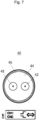
7 schematische Darstellung einer Ausführungsform einer differentiellen Leitung.
-
1 a perspective view of an embodiment of a connector; -
2 a view of theconnector 1 how it can be connected to a circuit board; -
3 an exploded view of theconnector 1 ; -
4 - 6 schematic representations of transmission methods for two coaxial cables with additional common outer shield; and -
7 schematic representation of an embodiment of a differential line.
Im Folgenden werden bevorzugte Ausführungsformen im Detail mit Bezug auf die beigefügten Figuren beschrieben.In the following, preferred embodiments are described in detail with reference to the accompanying figures.
Die Steckplätze sind insgesamt von einer Abschirmung 12 umgeben. Die Abschirmung 12 behindert nicht das Kontaktieren der komplementären Außen- und Innenleiter 6, 2 am Steckverbinder und Gegensteckverbinder, schirmt die Außenleiterkontakte 6 jedoch umfänglich ab. Insbesondere kann sich die Abschirmung 12 länger als die Außenleiterkontakte 6 erstrecken, um eine zuverlässige Abschirmung zu gewährleisten.The slots are surrounded by a
Die Abschirmung 12 ist ein Teil des Schirmgehäuses 10. Die Abschirmung 12 kann einteilig mit dem Schirmgehäuse 10 ausgebildet sein. Die Abschirmung 12 ist elektrisch leitfähig und zusammen mit dem Schirmgehäuse auf Masse gelegt, um als Abschirmung zu dienen. Das Schirmgehäuse 10 kann Vorsprünge 14 aufweisen.The
Über die Vorsprünge 14 kann das Schirmgehäuse 10 an einer PCB bzw. Leiterplatte befestigt und kontaktiert werden. Die Vorsprünge 14 dienen als Masseverbindung. Neben der Befestigung über die Vorsprünge 14 kann das Schirmgehäuse 10 über weitere Befestigungsmittel an der PCB befestigt werden, zum Bespiel durch Löten.The
Die Masseverbindung des Schirmgehäuses 10 ist getrennt, insbesondere galvanisch getrennt, von den Masseverbindungen der Außenleiterkontakte 6 und/oder Innenleiterkontakte 2.
Im Automotive Bereich gibt es Normen für die zulässige EMV Abstrahlung. Der vorliegende Steckverbinder 1 verringert durch das Schirmgehäuse 10, die Abschirmung 12 und dem Deckel 16 eine Abstrahlung, so dass diese im Normbereich liegt. Höhere Ströme verursachen eine stärkere EMV Abstrahlung. Bei dem vorliegenden Steckverbinder 1 kann durch das Schirmgehäuse 10, die Abschirmung 12 und dem Deckel 16 die Abstrahlung reduziert werden, so dass auch höhere Ströme übertragen werden können.In the automotive sector, there are standards for permissible EMC radiation. The
In den
BEZUGSZEICHENLISTEREFERENCE SYMBOL LIST
- 11
- SteckverbinderConnectors
- 22
- Innenleiterkontakteinner conductor contacts
- 44
- IsolatorenInsulators
- 66
- Außenleiterkontakteouter conductor contacts
- 77
- VerlängerungenExtensions
- 88
- Halterungbracket
- 1010
- Schirmgehäuseshield housing
- 1212
- Abschirmungshielding
- 1414
- Vorsprüngeprojections
- 1616
- DeckelLid
- 1818
- BefestigungsmittelFasteners
- 2020
- Codiergehäusecoding housing
- 2222
- Kontaktierungsbereichcontact area
- 2424
- Aufnahmeöffnungreceiving opening
- 2828
- BefestigungsmittelFasteners
- 31, 3231, 32
- geschirmte Leitungenshielded cables
- 3333
- Außenschirmoutdoor umbrella
- 4040
- differentielle Leitungdifferential line
- 4141
- erste Leitungfirst line
- 4242
- zweite Leitungsecond line
- 4444
- Isolationisolation
- 4646
- Abschirmungshielding
- LRLR
- Leitungsrichtungline direction
- XX
- erste Richtung (Steckrichtung)first direction (plug direction)
- YY
- zweite Richtungsecond direction
- ZZ
- dritte Richtungthird direction
ZITATE ENTHALTEN IN DER BESCHREIBUNGQUOTES INCLUDED IN THE DESCRIPTION
Diese Liste der vom Anmelder aufgeführten Dokumente wurde automatisiert erzeugt und ist ausschließlich zur besseren Information des Lesers aufgenommen. Die Liste ist nicht Bestandteil der deutschen Patent- bzw. Gebrauchsmusteranmeldung. Das DPMA übernimmt keinerlei Haftung für etwaige Fehler oder Auslassungen.This list of documents listed by the applicant was generated automatically and is included solely for the better information of the reader. The list is not part of the German patent or utility model application. The DPMA assumes no liability for any errors or omissions.
Zitierte PatentliteraturCited patent literature
- DE 102021103224 A1 [0004]DE 102021103224 A1 [0004]
Claims (8)
Priority Applications (3)
| Application Number | Priority Date | Filing Date | Title |
|---|---|---|---|
| DE102023108134.9A DE102023108134A1 (en) | 2023-03-30 | 2023-03-30 | CONNECTORS, CONNECTOR SYSTEMS AND TRANSMISSION METHODS |
| US18/602,203 US20240332870A1 (en) | 2023-03-30 | 2024-03-12 | Connector, connector system and transmission method |
| CN202410315089.4A CN118738898A (en) | 2023-03-30 | 2024-03-19 | Plug connector, plug connector system and transmission method |
Applications Claiming Priority (1)
| Application Number | Priority Date | Filing Date | Title |
|---|---|---|---|
| DE102023108134.9A DE102023108134A1 (en) | 2023-03-30 | 2023-03-30 | CONNECTORS, CONNECTOR SYSTEMS AND TRANSMISSION METHODS |
Publications (1)
| Publication Number | Publication Date |
|---|---|
| DE102023108134A1 true DE102023108134A1 (en) | 2024-10-02 |
Family
ID=92712928
Family Applications (1)
| Application Number | Title | Priority Date | Filing Date |
|---|---|---|---|
| DE102023108134.9A Pending DE102023108134A1 (en) | 2023-03-30 | 2023-03-30 | CONNECTORS, CONNECTOR SYSTEMS AND TRANSMISSION METHODS |
Country Status (3)
| Country | Link |
|---|---|
| US (1) | US20240332870A1 (en) |
| CN (1) | CN118738898A (en) |
| DE (1) | DE102023108134A1 (en) |
Citations (2)
| Publication number | Priority date | Publication date | Assignee | Title |
|---|---|---|---|---|
| DE102015106058A1 (en) * | 2015-04-21 | 2016-10-27 | Telegärtner Karl Gärtner GmbH | connector system |
| DE102021103224A1 (en) | 2021-02-11 | 2022-08-11 | Md Elektronik Gmbh | Multi-pin multi-phase connector and method of making the same |
Family Cites Families (4)
| Publication number | Priority date | Publication date | Assignee | Title |
|---|---|---|---|---|
| TWM399523U (en) * | 2010-09-06 | 2011-03-01 | Jye Tai Prec Ind Co Ltd | Improved high power socket connector |
| JP5836715B2 (en) * | 2011-09-07 | 2015-12-24 | 矢崎総業株式会社 | Shield connector |
| JP2015176657A (en) * | 2014-03-13 | 2015-10-05 | ホシデン株式会社 | connector |
| CN105490095A (en) * | 2014-09-16 | 2016-04-13 | 凡甲电子(苏州)有限公司 | Electric connector and electric connector combination |
-
2023
- 2023-03-30 DE DE102023108134.9A patent/DE102023108134A1/en active Pending
-
2024
- 2024-03-12 US US18/602,203 patent/US20240332870A1/en active Pending
- 2024-03-19 CN CN202410315089.4A patent/CN118738898A/en active Pending
Patent Citations (2)
| Publication number | Priority date | Publication date | Assignee | Title |
|---|---|---|---|---|
| DE102015106058A1 (en) * | 2015-04-21 | 2016-10-27 | Telegärtner Karl Gärtner GmbH | connector system |
| DE102021103224A1 (en) | 2021-02-11 | 2022-08-11 | Md Elektronik Gmbh | Multi-pin multi-phase connector and method of making the same |
Also Published As
| Publication number | Publication date |
|---|---|
| US20240332870A1 (en) | 2024-10-03 |
| CN118738898A (en) | 2024-10-01 |
Similar Documents
| Publication | Publication Date | Title |
|---|---|---|
| DE69227597T2 (en) | Electrical connector assembly | |
| EP2957003B1 (en) | Adapter | |
| DE29819314U1 (en) | Socket-like connector with filter device | |
| EP2629377A1 (en) | Cable for transferring signals | |
| DE102017110956A1 (en) | Device for transmitting energy and information via a charging cable for an electric vehicle | |
| DE202021100971U1 (en) | Automotive network communication devices and wiring with electromagnetic shielding | |
| DE102020104510B4 (en) | Charging socket for an electric vehicle | |
| DE102019121872A1 (en) | Hybrid connector | |
| EP2011194B1 (en) | Vehicle cable for serial data transmission | |
| WO2008014891A1 (en) | Plug connector for telecommunications and data technology | |
| DE102014219645A1 (en) | Electrical connection device for transmitting electrical energy and / or data, electrical system and motor vehicle | |
| DE102020115922A1 (en) | Connectors and connector adapters for multiple symmetrical signal transmission | |
| EP2290877B1 (en) | Data bus connection assembly | |
| EP1997194B1 (en) | Plug-type connector for telecommunications and data engineering | |
| DE102023108134A1 (en) | CONNECTORS, CONNECTOR SYSTEMS AND TRANSMISSION METHODS | |
| WO2020048890A1 (en) | Electrical distributor device, method for installation and signal transmission system | |
| DE202005009962U1 (en) | High frequency electrical connector for such as automobiles has a central core of insulating material with slots for connector sleeves | |
| EP4178043A1 (en) | Plug connector for data cable | |
| DE69213881T2 (en) | Device for connecting a transmission network to a plurality of subscribers | |
| DE102017006979A1 (en) | High-voltage arrangement for a motor vehicle with signal transmission via a high-voltage screen | |
| EP3168109A1 (en) | Electrical contact coupling | |
| DE202021104826U1 (en) | Ribbon cable for a vehicle charging connector | |
| DE102022108930B4 (en) | interface system on board a motor vehicle | |
| DE10209771B3 (en) | Distributor for foil conductors | |
| DE2458878C3 (en) | Switching device for switching signals in the VHF and UHF frequency range |
Legal Events
| Date | Code | Title | Description |
|---|---|---|---|
| R163 | Identified publications notified | ||
| R012 | Request for examination validly filed |