DE102020122286A1 - System and method for manufacturing a battery assembly - Google Patents
System and method for manufacturing a battery assembly Download PDFInfo
- Publication number
- DE102020122286A1 DE102020122286A1 DE102020122286.6A DE102020122286A DE102020122286A1 DE 102020122286 A1 DE102020122286 A1 DE 102020122286A1 DE 102020122286 A DE102020122286 A DE 102020122286A DE 102020122286 A1 DE102020122286 A1 DE 102020122286A1
- Authority
- DE
- Germany
- Prior art keywords
- channel
- state
- closure device
- battery
- feed channel
- Prior art date
- Legal status (The legal status is an assumption and is not a legal conclusion. Google has not performed a legal analysis and makes no representation as to the accuracy of the status listed.)
- Pending
Links
Images
Classifications
-
- H—ELECTRICITY
- H01—ELECTRIC ELEMENTS
- H01M—PROCESSES OR MEANS, e.g. BATTERIES, FOR THE DIRECT CONVERSION OF CHEMICAL ENERGY INTO ELECTRICAL ENERGY
- H01M10/00—Secondary cells; Manufacture thereof
- H01M10/04—Construction or manufacture in general
-
- H—ELECTRICITY
- H01—ELECTRIC ELEMENTS
- H01M—PROCESSES OR MEANS, e.g. BATTERIES, FOR THE DIRECT CONVERSION OF CHEMICAL ENERGY INTO ELECTRICAL ENERGY
- H01M10/00—Secondary cells; Manufacture thereof
- H01M10/60—Heating or cooling; Temperature control
- H01M10/65—Means for temperature control structurally associated with the cells
- H01M10/653—Means for temperature control structurally associated with the cells characterised by electrically insulating or thermally conductive materials
-
- H—ELECTRICITY
- H01—ELECTRIC ELEMENTS
- H01M—PROCESSES OR MEANS, e.g. BATTERIES, FOR THE DIRECT CONVERSION OF CHEMICAL ENERGY INTO ELECTRICAL ENERGY
- H01M50/00—Constructional details or processes of manufacture of the non-active parts of electrochemical cells other than fuel cells, e.g. hybrid cells
- H01M50/20—Mountings; Secondary casings or frames; Racks, modules or packs; Suspension devices; Shock absorbers; Transport or carrying devices; Holders
- H01M50/204—Racks, modules or packs for multiple batteries or multiple cells
- H01M50/207—Racks, modules or packs for multiple batteries or multiple cells characterised by their shape
- H01M50/209—Racks, modules or packs for multiple batteries or multiple cells characterised by their shape adapted for prismatic or rectangular cells
-
- Y—GENERAL TAGGING OF NEW TECHNOLOGICAL DEVELOPMENTS; GENERAL TAGGING OF CROSS-SECTIONAL TECHNOLOGIES SPANNING OVER SEVERAL SECTIONS OF THE IPC; TECHNICAL SUBJECTS COVERED BY FORMER USPC CROSS-REFERENCE ART COLLECTIONS [XRACs] AND DIGESTS
- Y02—TECHNOLOGIES OR APPLICATIONS FOR MITIGATION OR ADAPTATION AGAINST CLIMATE CHANGE
- Y02E—REDUCTION OF GREENHOUSE GAS [GHG] EMISSIONS, RELATED TO ENERGY GENERATION, TRANSMISSION OR DISTRIBUTION
- Y02E60/00—Enabling technologies; Technologies with a potential or indirect contribution to GHG emissions mitigation
- Y02E60/10—Energy storage using batteries
Landscapes
- Chemical & Material Sciences (AREA)
- Chemical Kinetics & Catalysis (AREA)
- Electrochemistry (AREA)
- General Chemical & Material Sciences (AREA)
- Engineering & Computer Science (AREA)
- Manufacturing & Machinery (AREA)
- Battery Mounting, Suspending (AREA)
Abstract
Die Erfindung betrifft ein System (10) und Verfahren zum Herstellen einer Batterieanordnung (12) aus zumindest einem Batteriemodul (14) und einem Batteriegehäuse (16). Das System (10) umfasst eine Zuführvorrichtung (18), die einen Zuführkanal (20) und eine Verschlusseinrichtung (22) aufweist, wobei der Zuführkanal (20) an einer Außenseite des Batteriegehäuses (16) angeordnet ist und wobei die Verschlusseinrichtung (22) in dem Batteriegehäuse (16) angeordnet ist und einen Durchgangskanal (24) aufweist. In einem ersten Zustand der Zuführvorrichtung (18) ist der Durchgangskanal (24) durch das Batteriegehäuse (16) hindurch an einen Boden des Batteriemoduls (14) ausgerichtet in einem zweiten Zustand ist der Durchgangskanal (24) durch das Batteriegehäuse (16) verschlossen, wobei der Zuführkanal (20) in dem zweiten Zustand durch eine Sollbruchstelle (26) von dem Durchgangskanal (24) getrennt wird.

Description
Die Erfindung betrifft ein System zum Herstellen einer Batterieanordnung aus zumindest einem Batteriemodul und einem Batteriegehäuse sowie ein Verfahren zum Herstellen einer Batterieanordnung mit einem solchen System.The invention relates to a system for producing a battery arrangement from at least one battery module and a battery housing and a method for producing a battery arrangement with such a system.
Bei einer Montage einer Batterieanordnung wird zur Verbesserung eines Wärmeübergangs ein Füllmaterial, ein sogenannter Gap Filler, eingesetzt. Dieser kann beispielsweise mittels eines Injektionsverfahrens bei einem Verbau der Batterieanordnung eingebracht werden. Hierfür ist ein entsprechender Zuführkanal notwendig, um das Füllmaterial einzubringen.When assembling a battery arrangement, a filling material, a so-called gap filler, is used to improve heat transfer. This can be introduced, for example, by means of an injection method when installing the battery arrangement. A corresponding feed channel is required for this in order to introduce the filling material.
Ein Nachteil dieses Zuführkanals für das Injektionsverfahren ist es, dass dieser Bauraum in der Batterieanordnung einnimmt, der nach der Montage Platz für andere Komponenten versperrt.A disadvantage of this feed channel for the injection process is that it takes up space in the battery arrangement, which blocks space for other components after assembly.
Aus der
Aus der
Aus der
Die Aufgabe der Erfindung ist es, ein verbessertes System und Verfahren zum Herstellen einer Batterieanordnung bereitzustellen, durch das ein verringerter Platzbedarf an der Batterieanordnung erreicht werden kann.The object of the invention is to provide an improved system and method for producing a battery arrangement, through which a reduced space requirement on the battery arrangement can be achieved.
Diese Aufgabe wird durch die unabhängigen Patentansprüche gelöst. Vorteilhafte Weiterbildungen der Erfindung sind in den abhängigen Ansprüchen, der folgenden Beschreibung sowie den Figuren offenbart.This object is solved by the independent patent claims. Advantageous developments of the invention are disclosed in the dependent claims, the following description and the figures.
Die Erfindung basiert auf der Idee, dass der Zuführkanal für das Füllmaterial als abnehmbares Bauteil ausgeführt wird, das nach einer Montage entfernt werden kann und somit Platz für andere Bauteile, zum Beispiel eine Sensorik oder eine Zellüberwachungselektronik, verfügbar ist. Um ein Rückquellen des Füllmaterials zu verhindern ist vorgesehen, einen Zugang nach dem Einfüllen wieder zu verschließen.The invention is based on the idea that the feed channel for the filling material is designed as a detachable component that can be removed after assembly and space is therefore available for other components, for example sensors or cell monitoring electronics. In order to prevent the filling material from swelling back, provision is made for an access to be closed again after filling.
Die Erfindung betrifft ein System zum Herstellen einer Batterieanordnung aus zumindest einem Batteriemodul und einem Batteriegehäuse, mit einer Zuführvorrichtung, die einen Zuführkanal und eine Verschlusseinrichtung aufweist, wobei der Zuführkanal an einer Außenseite des Batteriegehäuses angeordnet ist und wobei die Verschlusseinrichtung in dem Batteriegehäuse angeordnet ist und einen Durchgangskanal aufweist, wobei die Zuführvorrichtung einen ersten und einen zweiten Zustand aufweist, wobei in dem ersten Zustand der Durchgangskanal durch das Batteriegehäuse hindurch an einen Boden des Batteriemoduls ausgerichtet ist und der Zuführkanal mit dem Durchgangskanal zum Einleiten eines Füllmaterials an einer Verbindungsstelle verbunden ist und wobei in dem zweiten Zustand der Durchgangskanal durch das Batteriegehäuse verschlossen ist und der Zuführkanal von dem Durchgangskanal getrennt ist, wobei die Verbindungsstelle eine Sollbruchstelle aufweist, die dazu ausgebildet ist, den Zuführkanal von dem Durchgangskanal bei einer Änderung von dem ersten Zustand in den zweiten Zustand zu trennen.The invention relates to a system for producing a battery arrangement from at least one battery module and a battery housing, with a feed device having a feed channel and a closure device, the feed channel being arranged on an outside of the battery housing and the closure device being arranged in the battery housing and having a Having a through channel, wherein the feed device has a first and a second state, wherein in the first state the through channel is aligned through the battery housing to a bottom of the battery module and the feed channel is connected to the through channel for introducing a filling material at a connection point and wherein in the second state, the through-channel is closed by the battery housing and the supply channel is separated from the through-channel, the connection point having a predetermined breaking point which is designed to open the supply channel v on the pass-through channel upon a change from the first state to the second state.
Mit anderen Worten verläuft an einer Außenseite eines Batteriegehäuses ein Zuführkanal, der in einen Durchgangskanal mündet, wobei der Durchgangskanal durch das Batteriegehäuse hindurch an einen Boden eines Batteriemoduls zum Einleiten eines Füllmaterials führt. Der Zuführkanal ist mit dem Durchgangskanal an einer Verbindungsstelle verbunden, die eine Sollbruchstelle aufweist, so dass der Zuführkanal, insbesondere nach einem Einleitvorgang für das Füllmaterial, abgebrochen und entfernt werden kann. Des Weiteren kann der Durchgangskanal bei oder nach dem Abbruchvorgang verschlossen werden. Hierbei kann eine Änderung von einem ersten Zustand, in dem der Durchgangskanal offen ist und der Zuführkanal mit dem Durchgangskanal verbunden ist, zu einem zweiten Zustand, in dem der Durchgangskanal verschlossen ist und der Zuführkanal an der Sollbruchstelle abgebrochen und entfernt ist, mechanisch durchgeführt werden, vorzugsweise durch eine Änderung oder ein Verschließen einer Verschlusseinrichtung, in der sich der Durchgangskanal befindet. Die Verschlusseinrichtung kann vorzugsweise als ventilartiges Bauteil ausgebildet sein, das beispielsweise bei einer Drehung den Durchgangskanal verschließt.In other words, a supply channel runs on the outside of a battery housing and opens into a through-channel, with the through-channel leading through the battery housing to a bottom of a battery module for introducing a filling material. The feed channel is connected to the through-channel at a connection point which has a predetermined breaking point, so that the feed channel can be broken off and removed, in particular after the filling material has been introduced. Furthermore, the through-channel can be closed during or after the demolition process. Here, a change from a first state, in which the through-channel is open and the feed channel is connected to the through-channel, to a second state in which the through-channel is closed and the feed channel is broken off and removed at the predetermined breaking point, can be carried out mechanically, preferably by changing or closing a closure device in which the through-channel is located. The closure device can preferably be embodied as a valve-like component which, for example, closes the through-channel when it rotates.
Durch die Erfindung ergibt sich der Vorteil, dass nach einem Einfüllen eines Füllmaterials (Gap Filler) der für das Einfüllen verwendete Zuführkanal von der Außenseite des Batteriegehäuses abgetrennt werden kann, wodurch Platz für weiteren Bauraum entsteht, wobei an dem frei gewordenen Platz weitere Bauteile, wie beispielsweise eine Sensorik und/oder eine Zellüberwachungselektronik, angebracht werden können. Insgesamt kann dadurch eine bessere Bauraumausnutzung für die Batterieanordnung erreicht werden, indem auf einen festen Zuführkanal verzichtet wird.The invention has the advantage that after filling in a filling material (gap filler), the feed channel used for filling can be separated from the outside of the battery housing, which creates space for further installation space, with further components such as for example a sensor system and/or cell monitoring electronics. Overall, a better use of space for the battery arrangement can be achieved in that a fixed feed channel is dispensed with.
Zu der Erfindung gehören auch Ausführungsformen, durch die sich weitere Vorteile ergeben.The invention also includes embodiments that result in further advantages.
Eine Ausführungsform sieht vor, dass die Verschlusseinrichtung eine Zylinderform aufweist und der Durchgangskanal in einer Radialrichtung der Zylinderform angeordnet ist, wobei die Verschlusseinrichtung in einer Aussparung des Batteriegehäuses zwischen dem ersten Zustand und dem zweiten Zustand drehbar ausgebildet ist, wobei die Verschlusseinrichtung dazu ausgebildet ist, durch Drehung von dem ersten Zustand in den zweiten Zustand die Verbindungsstelle des Zuführkanals und des Durchgangskanals mittels einer Krafteinwirkung auf die Sollbruchstelle zu trennen und den Durchgangskanal zumindest auf einer Seite von einer Wand des Batteriegehäuses zu verschließen. Mit anderen Worten weist die Verschlusseinrichtung eine Zylinderform auf, durch die hindurch der Durchgangskanal verläuft, beispielsweise entlang eines Durchmessers der Zylinderform. Die zylinderförmige Verschlusseinrichtung kann in einer Aussparung des Batteriegehäuses angeordnet sein, so dass in dem ersten Zustand eine Seite des Durchgangskanals zu dem Boden des Batteriemoduls ausgerichtet ist und die andere Seite des Durchgangskanals zu einer Außenseite des Batteriegehäuses, wobei die nach außen zeigende Seite des Durchgangskanals in dem ersten Zustand über die Sollbruchstelle mit dem Zuführkanal verbunden ist und somit für ein Einleiten des Füllmaterials geöffnet ist. Durch Drehung der zylinderförmigen Verschlusseinrichtung kann der Durchgangskanal nach innen gedreht werden, wobei hierbei der Zuführkanal abgebrochen werden kann, insbesondere wenn der Zuführkanal durch die Drehung an die Außenseite des Batteriegehäuses gedrückt wird. Ist die Verschlusseinrichtung in den zweiten Zustand gedreht, kann vorzugsweise der Durchgangskanal an zumindest einer Seite, vorzugsweise an beiden Seiten, durch die Wand des Batteriegehäuses begrenzt und somit abgeschlossen sein. Durch diese Ausführungsform ergibt sich der Vorteil, dass eine einfache und platzsparende Möglichkeit geschaffen werden kann, in einem ersten Zustand einen Zugang zu dem Boden des Batteriemoduls bereitzustellen und in dem zweiten Zustand den Durchgangskanal zu verschließen und den Zuführkanal zu entfernen.One embodiment provides that the closure device has a cylindrical shape and the passage channel is arranged in a radial direction of the cylindrical shape, the closure device being designed to be rotatable in a recess of the battery housing between the first state and the second state, the closure device being designed to Rotation from the first state to the second state to separate the connection point of the feed channel and the through channel by means of a force on the predetermined breaking point and to close the through channel at least on one side of a wall of the battery housing. In other words, the closure device has a cylindrical shape through which the through-channel runs, for example along a diameter of the cylindrical shape. The cylindrical closure device can be arranged in a recess of the battery housing, so that in the first state one side of the through-channel is aligned with the bottom of the battery module and the other side of the through-channel with an outside of the battery housing, with the side of the through-channel pointing outwards in is connected to the feed channel via the predetermined breaking point in the first state and is therefore open for the introduction of the filling material. By rotating the cylindrical closure device, the through-channel can be turned inwards, in which case the feed channel can be broken off, in particular if the feed channel is pressed against the outside of the battery housing by the rotation. If the closure device is turned into the second state, the through-channel can preferably be delimited on at least one side, preferably on both sides, by the wall of the battery housing and thus closed off. This embodiment has the advantage that a simple and space-saving possibility can be created to provide access to the bottom of the battery module in a first state and to close the through-channel and remove the feed channel in the second state.
In einer weiteren Ausführungsform ist vorgesehen, dass zumindest teilweise um die Zylinderform der Verschlusseinrichtung herum ein Band angebracht ist, wobei das Band dazu ausgebildet ist, bei einer Zugkraft auf das Band die Verschlusseinrichtung von dem ersten in den zweiten Zustand zu drehen. Mit anderen Worten ist ein Band derart um die Zylinderform der Verschlusseinrichtung gewickelt, dass bei einem Zug an dem Band die Verschlusseinrichtung gedreht wird, um diese von dem ersten in den zweiten Zustand zu drehen. Das bedeutet, dass das Band bei einer Zugkraft von der Zylinderform abgerollt wird, wobei sich der Zylinder bei dem Abrollen dreht. Durch diese Ausführungsform ergibt sich der Vorteil, dass die Verschlusseinrichtung leicht von dem ersten in den zweiten Zustand gedreht werden kann.A further embodiment provides that a band is fitted at least partially around the cylindrical shape of the closure device, the band being designed to rotate the closure device from the first to the second state when the band is subjected to a tensile force. In other words, a band is wrapped around the cylinder shape of the closure device in such a way that when the band is pulled, the closure device is rotated in order to rotate it from the first to the second state. This means that the tape is unrolled from the cylindrical shape when there is a pulling force, with the cylinder rotating as it unwinds. This embodiment has the advantage that the closure device can easily be rotated from the first to the second state.
Vorzugsweise ist vorgesehen, dass das Band an der Verschlusseinrichtung angeklebt ist. Hierdurch ergibt sich der Vorteil, dass nach einem Zug an dem Band, um die Verschlusseinrichtung von dem ersten in den zweiten Zustand zu bringen, das Band an der Klebestelle leicht entfernt werden kann und so mehr Platz für weitere Bauteile bereitgestellt werden kann. Alternativ kann das Band auch fest an der Verschlusseinrichtung angebracht sein und durch ein Abschneiden entfernt werden.Provision is preferably made for the band to be glued to the closure device. This results in the advantage that after a pull on the tape in order to bring the closure device from the first to the second state, the tape can be easily removed at the splice and more space can thus be made available for further components. Alternatively, the band can also be firmly attached to the closure device and removed by cutting it off.
Besonders bevorzugt ist vorgesehen, dass die Verbindungsstelle den Zuführkanal mit dem Durchgangskanal in dem ersten Zustand an zwei Bereichen verbindet, wobei der erste Bereich die Sollbruchstelle umfasst und bei dem zweiten Bereich der Zuführkanal mit dem Durchgangskanal über das Band verbunden ist, dass an der Verschlusseinrichtung und dem Zuführkanal aufgeklebt ist. Mit anderen Worten sind der Zuführkanal und der Durchgangskanal zum einen über die Sollbruchstelle verbunden und zum anderen über eine Klebeverbindung des Bands. Somit kann für den ersten Zustand eine Dichtung der Kanäle erreicht werden, die ein Einleiten des Füllmaterials verbessert. Des Weiteren kann mit dieser Ausführungsform der Zuführkanal nach Einbringen des Füllmaterials leicht entfernt werden.Provision is particularly preferably made for the connection point to connect the feed channel to the through channel in two areas in the first state, with the first area comprising the predetermined breaking point and in the second area the feed channel being connected to the through channel via the band that is attached to the closure device and is glued to the feed channel. In other words, the feed channel and the through-channel are connected on the one hand via the predetermined breaking point and on the other hand via an adhesive connection of the tape. A seal of the channels can thus be achieved for the first state, which improves the introduction of the filling material. Furthermore, with this embodiment, the feed channel can be easily removed after the filling material has been introduced.
Eine weitere Ausführungsform sieht vor, dass die Verschlusseinrichtung eine Arretierungseinrichtung aufweist, die dazu ausgebildet ist, die Verschlusseinrichtung in dem zweiten Zustand zu arretieren. Mit anderen Worten ist die Arretierungseinrichtung dazu ausgebildet, die Verschlusseinrichtung in dem zweiten Zustand zu fixieren. Beispielsweise kann die Arretierungseinrichtung eine Noppe oder einen Federstift aufweisen, der in die Verschlusseinrichtung einrastet oder aus der Verschlusseinrichtung heraus in ein Gegenstück in der Aussparung des Batteriegehäuses. Durch diese Ausführungsform ergibt sich der Vorteil, dass der Durchgangskanal in dem zweiten Zustand fest verschlossen bleibt und ein Rückquellen des Füllmaterials verhindert werden kann.A further embodiment provides that the closure device has a locking device which is designed to lock the closure device in the second state. In other words, the locking device is designed to fix the closure device in the second state. For example, the locking device can have a nub or a spring pin that snaps into the locking device or out of the locking device into a counterpart in the recess of the battery housing. This embodiment results in the advantage that the passage channel remains firmly closed in the second state and the filling material can be prevented from swelling back.
Vorzugsweise ist vorgesehen, dass der Zuführkanal abnehmbar an der Außenseite des Batteriegehäuses angeordnet ist. Das heißt, dass der Zuführkanal nicht fest mit der Außenseite des Batteriegehäuses verbunden ist, sondern vorzugsweise nur mit der Verbindungsstelle zu dem Durchgangskanal oder über lösbare Befestigungsmittel. Beispielsweise kann der Zuführkanal an der Außenseite des Batteriegehäuses angeklebt oder angeschraubt sein. Eine solche Verbindung ist leicht lösbar, wodurch der Zuführkanal verbessert entfernt werden kann und somit mehr Bauraum bereitgestellt werden kann.Provision is preferably made for the feed channel to be arranged in a removable manner on the outside of the battery housing. This means that the feed channel is not firmly connected to the outside of the battery housing, but preferably only to the connection point to the through channel or via detachable fastening means. For example, the feed channel can be glued or screwed to the outside of the battery housing. Such a connection can be easily detached, as a result of which the feed channel can be removed in an improved manner and more installation space can thus be made available.
Insbesondere ist vorgesehen, dass die Verschlusseinrichtung in einer Endplatte des Batteriegehäuses angeordnet ist und der Zuführkanal an der Endplatte entlang nach oben über das Batteriemodul hinaus angeordnet ist. Mit anderen Worten ist die Verschlusseinrichtung in eine Endplatte (endplate) und der Zuführkanal entlang dieser Endplatte nach üben über das Batteriemodul hinaus angeordnet. Hierdurch ergibt sich der Vorteil, dass für eine Injektionsfüllung der Zuführkanal leicht erreichbar ist und an der Endplatte nach Entfernen des Zuführkanals mehr Bauraum für weitere Komponenten bereitgestellt werden kann.In particular, it is provided that the closure device is arranged in an end plate of the battery housing and the feed channel is arranged along the end plate upwards beyond the battery module. In other words, the closure device is arranged in an end plate (end plate) and the feed channel is arranged along this end plate beyond the battery module. This results in the advantage that the feed channel can be easily reached for an injection filling and more installation space can be made available for further components on the end plate after the feed channel has been removed.
Eine weitere Ausführungsform sieht vor, dass der Durchgangskanal dazu ausgebildet ist, in dem ersten Zustand das Füllmaterial in eine Kanalstruktur des Bodens des Batteriemoduls zu leiten. Mit anderen Worten führt der Durchgangskanal direkt in eine Kanalstruktur des Bodens des Batteriemoduls, von wo aus das Füllmaterial gleichmäßig an dem Boden des Batteriemoduls verteilt werden kann. Durch diese Ausführungsform ergibt sich der Vorteil, dass mittels des Leitens des Füllmaterials durch den Durchgangskanal in die Kanalstruktur des Bodens eine verbesserte Ausbreitung des Füllmaterials bereitgestellt werden kann.A further embodiment provides that the through-channel is designed to guide the filling material into a channel structure of the base of the battery module in the first state. In other words, the through-channel leads directly into a channel structure in the bottom of the battery module, from where the filling material can be distributed evenly on the bottom of the battery module. This embodiment results in the advantage that an improved spreading of the filling material can be provided by guiding the filling material through the through-channel into the channel structure of the floor.
Ein weiterer Aspekt der Erfindung betrifft ein Verfahren zum Herstellen einer Batterieanordnung mit einem System nach einem der vorhergehenden Ausführungsformen, wobei ein Füllmaterial über einen Zuführkanal und einen Durchgangskanal einer Verschlusseinrichtung an einen Boden eines Batteriemoduls eingeleitet wird, wobei sich die Verschlusseinrichtung für das Einleiten des Füllmaterials in einem ersten Zustand befindet, wobei nach Abschluss des Einleitens des Füllmaterials die Verschlusseinrichtung in einen zweiten Zustand gebracht wird, wobei in dem zweiten Zustand der Durchgangskanal durch das Batteriegehäuse verschlossen wird und der Zuführkanal an einer Sollbruchstelle einer Verbindungsstelle zwischen dem Zuführkanal und dem Durchgangskanal bei der Änderung in den zweiten Zustand abgebrochen und entfernt wird. Hierdurch ergeben sich gleiche Vorteile und Variationsmöglichkeiten wie bei dem System.A further aspect of the invention relates to a method for producing a battery arrangement with a system according to one of the preceding embodiments, wherein a filling material is introduced via a feed channel and a through-channel of a closure device to a base of a battery module, the closure device for introducing the filling material being located in is in a first state, with the closing device being brought into a second state after the introduction of the filling material has been completed, with the through-channel being closed by the battery housing in the second state and the supply channel being closed at a predetermined breaking point of a connection point between the supply channel and the through-channel during the change to the second state is aborted and removed. This results in the same advantages and possible variations as with the system.
Zu der Erfindung gehören auch Weiterbildungen des erfindungsgemäßen Verfahrens, die Merkmale aufweisen, wie sie bereits im Zusammenhang mit den Weiterbildungen des erfindungsgemäßen Systems beschrieben worden sind. Aus diesem Grund sind die entsprechenden Weiterbildungen des erfindungsgemäßen Verfahrens hier nicht noch einmal beschrieben.The invention also includes developments of the method according to the invention, which have features as have already been described in connection with the developments of the system according to the invention. For this reason, the corresponding developments of the method according to the invention are not described again here.
Die Erfindung umfasst auch die Kombinationen der Merkmale der beschriebenen Ausführungsformen. Die Erfindung umfasst also auch Realisierungen, die jeweils eine Kombinationen der Merkmale mehrerer der beschriebenen Ausführungsformen aufweisen, sofern die Ausführungsformen nicht als sich gegenseitig ausschließend beschrieben wurden.The invention also includes the combinations of features of the described embodiments. The invention also includes implementations that each have a combination of the features of several of the described embodiments, provided that the embodiments were not described as mutually exclusive.
Im Folgenden sind Ausführungsbeispiele der Erfindung beschrieben. Hierzu zeigt:
-
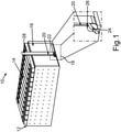
1 eine Perspektivansicht auf ein schematisches System zum Herstellen einer Batterieanordnung gemäß einer beispielhaften Ausführungsform; -
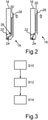
2 eine schematische Seitenansicht eines Systems zum Herstellen einer Batterieanordnung gemäß einer beispielhaften Ausführungsform; -
3 ein schematisches Verfahrensdiagramm zum Herstellen einer Batterieanordnung gemäß einer beispielhaften Ausführungsform.
-
1 a perspective view of a schematic system for manufacturing a battery assembly according to an exemplary embodiment; -
2 12 shows a schematic side view of a system for manufacturing a battery assembly according to an exemplary embodiment; -
3 FIG. 12 is a schematic process diagram for manufacturing a battery assembly according to an exemplary embodiment.
Bei den im Folgenden erläuterten Ausführungsbeispielen handelt es sich um bevorzugte Ausführungsformen der Erfindung. Bei den Ausführungsbeispielen stellen die beschriebenen Komponenten der Ausführungsformen jeweils einzelne, unabhängig voneinander zu betrachtende Merkmale der Erfindung dar, welche die Erfindung jeweils auch unabhängig voneinander weiterbilden. Daher soll die Offenbarung auch andere als die dargestellten Kombinationen der Merkmale der Ausführungsformen umfassen. Des Weiteren sind die beschriebenen Ausführungsformen auch durch weitere der bereits beschriebenen Merkmale der Erfindung ergänzbar.The exemplary embodiments explained below are preferred embodiments of the invention. In the exemplary embodiments, the described components of the embodiments each represent individual features of the invention that are to be considered independently of one another and that also develop the invention independently of one another. Therefore, the disclosure is also intended to encompass combinations of the features of the embodiments other than those illustrated. Furthermore, the described embodiments can also be supplemented by further features of the invention that have already been described.
In den Figuren bezeichnen gleiche Bezugszeichen jeweils funktionsgleiche Elemente.In the figures, the same reference symbols designate elements with the same function.
In
Vorzugsweise ist vorgesehen, dass die Verschlusseinrichtung 22 eine Zylinderform aufweist und der Durchgangskanal 24 in einer Radialrichtung der Zylinderform hindurch verläuft, so dass der Durchgangskanal 24 durch die Wand der Endplatte 16 hindurchtritt. Die zylinderförmige Verschlusseinrichtung 22 kann insbesondere in einer Aussparung der Endplatte 16 angeordnet und drehbar gelagert sein. Somit kann die Verschlusseinrichtung 22 durch eine Drehung von dem ersten Zustand in einen zweiten Zustand versetzt werden.Provision is preferably made for the
Bei der Drehung in den zweiten Zustand kann insbesondere eine Krafteinwirkung auf die Verbindungsstelle des Zuführkanals 20 und des Durchgangskanals 24 einwirken, wobei die Verbindungsstelle vorzugsweise eine Sollbruchstelle 26 aufweist, die bei der Krafteinwirkung die Kanäle voneinander trennt. Das heißt, dass bei der Drehung von dem ersten in den zweiten Zustand der Zuführkanal 20 von der Verschlusseinrichtung 22, insbesondere von dem Durchgangskanal 24, abbricht und entnommen werden kann. Zusätzlich kann sich die zylinderförmige Verschlusseinrichtung 22 in eine Position drehen, in der der Durchgangskanal 24 von einer Wand der Endplatte 16 verschlossen wird, um ein Rückquellen des Füllmaterials zu vermeiden.During the rotation into the second state, a force can in particular act on the connection point of the
Um eine Krafteinwirkung auf die Verschlusseinrichtung 22 zur Änderung von dem ersten Zustand in den zweiten Zustand aufzubringen, kann ein Band 28 bereitgestellt sein, das zumindest teilweise um die Zylinderform der Verschlusseinrichtung 22 herum angebracht ist, wobei bei einem Zug auf das Band 28 die Verschlusseinrichtung 22 gedreht wird. Durch die Drehung kann eine Kraft auf die Sollbruchstelle 26 einwirken, wodurch der Zuführkanal 20 abgetrennt wird und der Durchgangskanal 24 verschlossen werden kann.In order to apply a force to the
Besonders bevorzugt kann der Zuführkanal 20 mit der zylinderförmigen Verschlusseinrichtung 22 an zwei Bereichen verbunden sein, wobei der eine Bereich die Sollbruchstelle aufweist und an dem zweiten Bereich der Zuführkanal 20 mit dem Durchgangskanal 24 über das Band 28 verbunden ist, das die Verschlusseinrichtung 22 mit dem Zuführkanal 20 aneinanderklebt. Diese Klebeverbindung kann insbesondere in dem zweiten Zustand getrennt werden, um den Zuführkanal 20 von der Verschlusseinrichtung 22 trennen zu können.Particularly preferably, the
Durch das Trennen des Zuführkanals 20 von der Verschlusseinrichtung 22 ergibt sich der Vorteil, dass an der Endplatte 16 Platz für weiteren Bauraum bereitgestellt werden kann, wodurch weitere Sensorik an dem Batteriemodul 14 angeordnet werden kann.Separating the
Vorzugsweise ist zusätzlich vorgesehen, dass die Verschlusseinrichtung 22 eine Arretierungseinrichtung (nicht gezeigt) aufweist, beispielsweise eine Noppe, die die Verschlusseinrichtung 22 in dem zweiten Zustand fixiert, so dass der Durchgangskanal 24 verschlossen bleibt und ein Rückquellen des Füllmaterials verhindert werden kann.Provision is preferably additionally made for the
In
Nach Einleiten des Füllmaterials kann durch einen Zug an dem Band 28 die Verschlusseinrichtung 22 in den zweiten Zustand versetzt werden, der auf der rechten Seite der
In dem zweiten Zustand kann durch Drehung der Verschlusseinrichtung 22 die Verbindung zwischen dem Zuführkanal 20 und dem Durchgangskanal 24 an der die Sollbruchstelle 26 getrennt worden sein, wobei die Verschlusseinrichtung 22 durch die Drehung in eine Position gedreht ist, in der der Durchgangskanal 24 von der Wand der Endplatte 16 verschlossen wird. So kann ein Rückquellen des Füllmaterials verhindert werden. Der Zuführkanal 20 kann anschließend, beispielsweise indem das Band 28 zusätzlich von der Verschlusseinrichtung 22 entfernt wird, von der Endplatte 16 entnommen werden, wodurch auf dieser Seite der Endplatte 16 weiterer Bauraum entsteht.In the second state, the connection between the
In
Nach Beendigung des Einleitvorgangs kann in einem Schritt S12 die Verschlusseinrichtung 22 von dem ersten Zustand in den zweiten Zustand gebracht werden, indem beispielsweise an einem Band 28 eine Zugkraft aufgebracht wird, durch die sich die Verschlusseinrichtung 22, die insbesondere zylinderförmig sein kann, dreht. Durch die Drehung kann eine Sollbruchstelle 26 den Zuführkanal 20 und den Durchgangskanal 24 voneinander trennen und den Durchgangskanal 24 in eine Position bringen, in der ein Durchgang des Durchgangskanals 24 von einer Wand eines Batteriegehäuses 16 versperrt und somit verschlossen wird.After completion of the initiation process, the
Schließlich kann in einem Schritt S14 der abgebrochene Zuführkanal 20 von dem Batteriegehäuse 16 entfernt werden, um zusätzlichen Bauraum an dem Batteriegehäuse 16 bereitzustellen.Finally, in a step S14, the broken-off
In einer weiteren beispielhaften Ausführungsform besteht ein Aspekt darin, dass ein Gap-Filler-Einfüllkanal (Zuführkanal 20) als abnehmbares Bauteil ausgeführt wird, das nach der Montage entfernt werden kann und somit Platz für andere Bauteile entsteht. Um ein Rückquellen des Gap Fillers zu verhindern soll der Zugang (Durchgangskanal 24) wieder verschlossen werden. Hierzu kann in einer Endplatte 16 des Batteriemoduls 14 eine Aussparung vorgesehen sein, in der ein zylinderförmiger Verschlussmechanismus (Verschlusseinrichtung 22) angebracht wird. An diesem ist ein Einspritzkanal (Zuführkanal 20) angespritzt mit einer definierten Sollbruchstelle 26. Zudem sind der Verschlussmechanismus 22 und der Injektionskanal 20 über ein aufgeklebtes Band 28 verbunden.In a further exemplary embodiment, one aspect is that a gap filler filling channel (supply channel 20) is designed as a removable component that can be removed after assembly, thus creating space for other components. In order to prevent the gap filler from swelling back, the access (passage channel 24) should be closed again. For this purpose, a recess can be provided in an
Nach der Montage des Batteriemoduls 14 wird über den Zuführkanalkanal 20 und den Verschlussmechanismus 22 der Gap Filler unter das Batteriemodul 14 injiziert. Nach Abschluss der Einbringung des Gap Fillers wird der Zuführkanal 20 an dem aufgeklebten Band 28 nach oben gezogen. Dadurch dreht sich der Verschlussmechanismus 22 und verschließt den Zugang (Durchgangskanal 24) für den Gap Filler. Zudem bricht der Zuführkanal 20 an der Sollbruchstelle 26 ab und kann entnommen werden. Außerdem kann sich das Band 28, das insbesondere aufgeklebt sein kann, von dem Verschlussmechanismus 22 lösen. Somit kann der Raum des Zuführkanals 20 durch andere Komponenten genutzt werden.After the
Insgesamt zeigen die Beispiele, wie durch die Erfindung ein Injektorverschluss für einen Gap Filler bereitgestellt werden kann.Overall, the examples show how an injector closure for a gap filler can be provided by the invention.
ZITATE ENTHALTEN IN DER BESCHREIBUNGQUOTES INCLUDED IN DESCRIPTION
Diese Liste der vom Anmelder aufgeführten Dokumente wurde automatisiert erzeugt und ist ausschließlich zur besseren Information des Lesers aufgenommen. Die Liste ist nicht Bestandteil der deutschen Patent- bzw. Gebrauchsmusteranmeldung. Das DPMA übernimmt keinerlei Haftung für etwaige Fehler oder Auslassungen.This list of documents cited by the applicant was generated automatically and is included solely for the better information of the reader. The list is not part of the German patent or utility model application. The DPMA assumes no liability for any errors or omissions.
Zitierte PatentliteraturPatent Literature Cited
- DE 102018206800 A1 [0004]DE 102018206800 A1 [0004]
- DE 102018208070 A1 [0005]DE 102018208070 A1 [0005]
- DE 102017116420 A1 [0006]DE 102017116420 A1 [0006]
Claims (10)
Priority Applications (1)
| Application Number | Priority Date | Filing Date | Title |
|---|---|---|---|
| DE102020122286.6A DE102020122286A1 (en) | 2020-08-26 | 2020-08-26 | System and method for manufacturing a battery assembly |
Applications Claiming Priority (1)
| Application Number | Priority Date | Filing Date | Title |
|---|---|---|---|
| DE102020122286.6A DE102020122286A1 (en) | 2020-08-26 | 2020-08-26 | System and method for manufacturing a battery assembly |
Publications (1)
| Publication Number | Publication Date |
|---|---|
| DE102020122286A1 true DE102020122286A1 (en) | 2022-03-03 |
Family
ID=80221081
Family Applications (1)
| Application Number | Title | Priority Date | Filing Date |
|---|---|---|---|
| DE102020122286.6A Pending DE102020122286A1 (en) | 2020-08-26 | 2020-08-26 | System and method for manufacturing a battery assembly |
Country Status (1)
| Country | Link |
|---|---|
| DE (1) | DE102020122286A1 (en) |
Citations (5)
| Publication number | Priority date | Publication date | Assignee | Title |
|---|---|---|---|---|
| DE102017116420A1 (en) | 2016-07-22 | 2018-01-25 | Ford Global Technologies, Llc | BATTERY TERMINAL MATERIAL INSTALLATION ASSEMBLY AND METHOD |
| DE102018206800A1 (en) | 2018-05-03 | 2019-11-07 | Audi Ag | System for producing a battery arrangement |
| DE102018208070A1 (en) | 2018-05-23 | 2019-11-28 | Audi Ag | A method for manufacturing a battery module device for a motor vehicle, battery module device for a motor vehicle and motor vehicle with a battery module device |
| DE102018219732A1 (en) | 2018-11-16 | 2020-05-20 | Audi Ag | Battery housing for receiving a battery module, battery module arrangement, motor vehicle and method for introducing a heat-conducting element into a battery housing |
| DE102018221988A1 (en) | 2018-12-17 | 2020-06-18 | Audi Ag | Battery housing for receiving a battery module, battery module arrangement, motor vehicle and method for introducing a heat-conducting element into a battery housing |
-
2020
- 2020-08-26 DE DE102020122286.6A patent/DE102020122286A1/en active Pending
Patent Citations (5)
| Publication number | Priority date | Publication date | Assignee | Title |
|---|---|---|---|---|
| DE102017116420A1 (en) | 2016-07-22 | 2018-01-25 | Ford Global Technologies, Llc | BATTERY TERMINAL MATERIAL INSTALLATION ASSEMBLY AND METHOD |
| DE102018206800A1 (en) | 2018-05-03 | 2019-11-07 | Audi Ag | System for producing a battery arrangement |
| DE102018208070A1 (en) | 2018-05-23 | 2019-11-28 | Audi Ag | A method for manufacturing a battery module device for a motor vehicle, battery module device for a motor vehicle and motor vehicle with a battery module device |
| DE102018219732A1 (en) | 2018-11-16 | 2020-05-20 | Audi Ag | Battery housing for receiving a battery module, battery module arrangement, motor vehicle and method for introducing a heat-conducting element into a battery housing |
| DE102018221988A1 (en) | 2018-12-17 | 2020-06-18 | Audi Ag | Battery housing for receiving a battery module, battery module arrangement, motor vehicle and method for introducing a heat-conducting element into a battery housing |
Similar Documents
| Publication | Publication Date | Title |
|---|---|---|
| DE69711787T2 (en) | A corrugated tube and an automatic cable loader | |
| DE69505861T2 (en) | Two-part rotary switch with locking and wiring harness | |
| DE102018118821B4 (en) | HIGH PRESSURE TANK AND REINFORCING COAT WINDING PROCESS | |
| DE112010004634T5 (en) | Wire Holder | |
| DE102009057426A1 (en) | Locking device for use in or at electric vehicle for securing charging socket and charging plug of plug-in connector for electrical plug-in connection at charging station, has actuator or actuator housing connected with socket or plug | |
| DE2358890A1 (en) | LOCKING PIECE OR LOCK FOR A SEAT BELT | |
| WO2010133490A2 (en) | Fastening element and method for fastening an airbag of a vehicle occupant restraint system to a vehicle structure | |
| DE19701511C2 (en) | Grommet for the passage of electrical lines through walls, especially in motor vehicles | |
| DE102009002197A1 (en) | Fastening device for a cable | |
| DE202022103921U1 (en) | Fastening device for vehicle | |
| EP3743964B1 (en) | Holding assembly for an automotive charging system | |
| DE102017112144A1 (en) | Retaining clip for vehicles | |
| DE102005051582B4 (en) | Arrangement and method for attaching a brake force assistance device in a motor vehicle | |
| DE102023114384A1 (en) | Protective sleeve assembly and wiring harness | |
| DE102011001655A1 (en) | Fuel supply substructure of a vehicle | |
| DE102017123289A1 (en) | Method for the end-mounted mounting of a door handle carrier and door handle carrier mounting set | |
| EP3163094A1 (en) | Attachment device | |
| EP2421726B1 (en) | Airbag module for a vehicle occupant restraint system and method for the production thereof | |
| DE102020122286A1 (en) | System and method for manufacturing a battery assembly | |
| DE112021002933T5 (en) | MOUNTING STRUCTURE FOR ROOF MOUNT ANTENNA | |
| DE10012157C1 (en) | Gland for fitting electrical cable or supply line through wall aperture e.g. for automobile, has opening for cable or supply line enclosed by reception elements cooperating with expansion tool | |
| DE102020111968A1 (en) | Fastening arrangement of a storage module on a housing of an electrical energy store, motor vehicle and method for releasing such a fastening arrangement | |
| DE69924227T2 (en) | BOWDENZUG FOR MOTOR VEHICLE EQUIPMENT | |
| DE69707948T2 (en) | Method and device for applying an elastic tubular covering with clamping action on an element | |
| DE4106773B4 (en) | Fuel bundle for a nuclear reactor |
Legal Events
| Date | Code | Title | Description |
|---|---|---|---|
| R079 | Amendment of ipc main class |
Free format text: PREVIOUS MAIN CLASS: H01M0002020000 Ipc: H01M0050100000 |
|
| R163 | Identified publications notified |