DE112010004634T5 - Wire Holder - Google Patents

Wire Holder Download PDF

Info

Publication number
DE112010004634T5
DE112010004634T5 DE112010004634T DE112010004634T DE112010004634T5 DE 112010004634 T5 DE112010004634 T5 DE 112010004634T5 DE 112010004634 T DE112010004634 T DE 112010004634T DE 112010004634 T DE112010004634 T DE 112010004634T DE 112010004634 T5 DE112010004634 T5 DE 112010004634T5
Authority
DE
Germany
Prior art keywords
wire
wires
holder
main body
insertion holes
Prior art date
Legal status (The legal status is an assumption and is not a legal conclusion. Google has not performed a legal analysis and makes no representation as to the accuracy of the status listed.)
Withdrawn
Application number
DE112010004634T
Other languages
German (de)
Inventor
Harumi Kawase
Current Assignee (The listed assignees may be inaccurate. Google has not performed a legal analysis and makes no representation or warranty as to the accuracy of the list.)
Yazaki Corp
Original Assignee
Yazaki Corp
Priority date (The priority date is an assumption and is not a legal conclusion. Google has not performed a legal analysis and makes no representation as to the accuracy of the date listed.)
Filing date
Publication date
Application filed by Yazaki Corp filed Critical Yazaki Corp
Publication of DE112010004634T5 publication Critical patent/DE112010004634T5/en
Withdrawn legal-status Critical Current

Links

Images

Classifications

    • HELECTRICITY
    • H01ELECTRIC ELEMENTS
    • H01RELECTRICALLY-CONDUCTIVE CONNECTIONS; STRUCTURAL ASSOCIATIONS OF A PLURALITY OF MUTUALLY-INSULATED ELECTRICAL CONNECTING ELEMENTS; COUPLING DEVICES; CURRENT COLLECTORS
    • H01R4/00Electrically-conductive connections between two or more conductive members in direct contact, i.e. touching one another; Means for effecting or maintaining such contact; Electrically-conductive connections having two or more spaced connecting locations for conductors and using contact members penetrating insulation
    • H01R4/70Insulation of connections
    • HELECTRICITY
    • H01ELECTRIC ELEMENTS
    • H01RELECTRICALLY-CONDUCTIVE CONNECTIONS; STRUCTURAL ASSOCIATIONS OF A PLURALITY OF MUTUALLY-INSULATED ELECTRICAL CONNECTING ELEMENTS; COUPLING DEVICES; CURRENT COLLECTORS
    • H01R13/00Details of coupling devices of the kinds covered by groups H01R12/70 or H01R24/00 - H01R33/00
    • H01R13/58Means for relieving strain on wire connection, e.g. cord grip, for avoiding loosening of connections between wires and terminals within a coupling device terminating a cable
    • H01R13/582Means for relieving strain on wire connection, e.g. cord grip, for avoiding loosening of connections between wires and terminals within a coupling device terminating a cable the cable being clamped between assembled parts of the housing
    • H01R13/5829Means for relieving strain on wire connection, e.g. cord grip, for avoiding loosening of connections between wires and terminals within a coupling device terminating a cable the cable being clamped between assembled parts of the housing the clamping part being flexibly or hingedly connected to the housing
    • HELECTRICITY
    • H01ELECTRIC ELEMENTS
    • H01RELECTRICALLY-CONDUCTIVE CONNECTIONS; STRUCTURAL ASSOCIATIONS OF A PLURALITY OF MUTUALLY-INSULATED ELECTRICAL CONNECTING ELEMENTS; COUPLING DEVICES; CURRENT COLLECTORS
    • H01R4/00Electrically-conductive connections between two or more conductive members in direct contact, i.e. touching one another; Means for effecting or maintaining such contact; Electrically-conductive connections having two or more spaced connecting locations for conductors and using contact members penetrating insulation
    • H01R4/24Connections using contact members penetrating or cutting insulation or cable strands
    • H01R4/2416Connections using contact members penetrating or cutting insulation or cable strands the contact members having insulation-cutting edges, e.g. of tuning fork type
    • H01R4/242Connections using contact members penetrating or cutting insulation or cable strands the contact members having insulation-cutting edges, e.g. of tuning fork type the contact members being plates having a single slot
    • H01R4/2425Flat plates, e.g. multi-layered flat plates
    • H01R4/2429Flat plates, e.g. multi-layered flat plates mounted in an insulating base
    • H01R4/2433Flat plates, e.g. multi-layered flat plates mounted in an insulating base one part of the base being movable to push the cable into the slot
    • HELECTRICITY
    • H01ELECTRIC ELEMENTS
    • H01RELECTRICALLY-CONDUCTIVE CONNECTIONS; STRUCTURAL ASSOCIATIONS OF A PLURALITY OF MUTUALLY-INSULATED ELECTRICAL CONNECTING ELEMENTS; COUPLING DEVICES; CURRENT COLLECTORS
    • H01R13/00Details of coupling devices of the kinds covered by groups H01R12/70 or H01R24/00 - H01R33/00
    • H01R13/46Bases; Cases
    • H01R13/50Bases; Cases formed as an integral body
    • H01R13/501Bases; Cases formed as an integral body comprising an integral hinge or a frangible part
    • HELECTRICITY
    • H01ELECTRIC ELEMENTS
    • H01RELECTRICALLY-CONDUCTIVE CONNECTIONS; STRUCTURAL ASSOCIATIONS OF A PLURALITY OF MUTUALLY-INSULATED ELECTRICAL CONNECTING ELEMENTS; COUPLING DEVICES; CURRENT COLLECTORS
    • H01R13/00Details of coupling devices of the kinds covered by groups H01R12/70 or H01R24/00 - H01R33/00
    • H01R13/58Means for relieving strain on wire connection, e.g. cord grip, for avoiding loosening of connections between wires and terminals within a coupling device terminating a cable
    • H01R13/5833Means for relieving strain on wire connection, e.g. cord grip, for avoiding loosening of connections between wires and terminals within a coupling device terminating a cable the cable being forced in a tortuous or curved path, e.g. knots in cable

Landscapes

  • Details Of Connecting Devices For Male And Female Coupling (AREA)
  • Connections By Means Of Piercing Elements, Nuts, Or Screws (AREA)
  • Installation Of Indoor Wiring (AREA)

Abstract

Eine Aufgabe der Erfindung besteht darin, einen Draht-Halter zu schaffen, mit dem eine Endbehandlung eines Kabelbaums erleichtert werden kann, um die Herstellungskosten für den Kabelbaum zu reduzieren und die Zuverlässigkeit bei der Schneidklemm-Steckverbindung am Endabschnitt des Kabelbaums zu verbessern. Bei einem Draht-Halter 1, der einen Halter-Hauptkörper 5, der eine Vielzahl von Drähten 3 mit einem Draht-Ausrichtabschnitt 11 parallel halt, und eine Halter-Abdeckung 6 enthält, die Abschnitte 3a der Drähte 3, die über den Halter-Hauptkörper 5 herausgeführt werden, zusammen mit dem Halter-Hauptkörper 5 einschließt, ist der Draht-Ausrichtabschnitt 11 mit einer Vielzahl von Vorderenden-Isolierlöchern 14, über die vordere Endabschnitte 3b der Drähte 3 eingeführt werden, so dass die Drähte 3 parallel positioniert werden, und mit einem Loch 15 zum Einführen einer Isolierungs-Trennschneide versehen, über das eine Isolierungs-Trennschneide 31 von außen eingeführt wird. Jedes der Vorderenden-Einführlöcher 14 ist in einer sich verjüngenden Form ausgebildet, für die D2 ≤ d ≤ D1 gilt, wobei D1 einen Innendurchmesser jedes der Vorderenden-Einführlöcher 14 an einer Draht-Einführseite bezeichnet, D2 einen Innendurchmesser jedes der Vorderenden-Einführlöcher 1 an einer Draht-Ausführseite bezeichnet und d einen Außendurchmesser einer Ummantelung jedes der Drähte 3 bezeichnet.It is an object of the invention to provide a wire retainer with which finishing of a wire harness can be facilitated to reduce the manufacturing cost of the wire harness and improve the reliability of the insulation displacement connector at the end portion of the wire harness. In a wire holder 1, which includes a holder main body 5, which holds a plurality of wires 3 with a wire aligning portion 11 in parallel, and a holder cover 6, the portions 3a of the wires 3 that extend over the holder main body 5, together with the holder main body 5, the wire aligning portion 11 is provided with a plurality of front end insulating holes 14 through which front end portions 3b of the wires 3 are inserted so that the wires 3 are positioned in parallel, and with a hole 15 for inserting an insulation cutting blade through which an insulation cutting blade 31 is inserted from the outside. Each of the front end insertion holes 14 is formed in a tapered shape, D2 d D1, where D1 denotes an inside diameter of each of the front end insertion holes 14 on a wire insertion side, D2 denotes an inside diameter of each of the front end insertion holes 1 denotes a wire lead-out side; and d denotes an outer diameter of a cover of each of the wires 3.

Description

Technisches GebietTechnical area

Die vorliegende Erfindung betrifft einen Draht-Halter, mit dem eine Endbehandlung eines Kabelbaums erleichtert werden kann, wenn er anstelle eines Schneidklemm-Steckverbinders an einem. Endabschnitt des Kabelbaums angebracht wird, um die Herstellungskosten für den Kabelbaum zu verringern.The present invention relates to a wire holder with which a final treatment of a wire harness can be facilitated when, instead of a insulation displacement connector on a. End portion of the wiring harness is mounted to reduce the manufacturing cost of the wiring harness.

Technischer HintergrundTechnical background

Im Allgemeinen ist ein Kabelbaum, der in einem Fahrzeug verlegt wird, so eingerichtet, dass er einen Verbinder aufweist, der an einem Endabschnitt desselben zur Anschlussverbindung mit einer Vorrichtung angebracht wird.In general, a wiring harness laid in a vehicle is arranged to have a connector attached to an end portion thereof for connection with a device.

Des Weiteren ist bei den Verbindern zum Verbinden mit dem Endabschnitt des Kabelbaums in den letzten Jahren zunehmend der Schneidklemm-Steckverbinder zum Einsatz gekommen. Es sind verschiedene Typen von Schneidklemm-Steckverbindern einschließlich eines Typs Schneidklemm-Steckverbinder, wie er in Patentdokument 1 beschrieben ist und bei dem Isolierungen von Drähten zur elektrischen Verbindung einzeln durchtrennt werden, oder eines Typs Schneidklemm-Steckverbinder vorgeschlagen worden, wie er in Patentdokument 2 beschrieben ist und bei dem Isolierungen von Drähten zur elektrischen Verbindung gemeinsam durchtrennt werden.Further, in the connectors for connecting to the end portion of the wiring harness in recent years, the insulation displacement connector has been increasingly used. There are various types of insulation displacement connectors, including a type of insulation displacement connector as disclosed in patent document 1 and in which insulations of wires for electrical connection are severed individually, or a type of insulation displacement connector has been proposed, as disclosed in patent document 2 is described and are severed in the insulation of wires for electrical connection together.

Der Schneidklemm-Steckverbinder von dem Typ, bei dem die Isolierungen einzeln durchtrennt werden, ist so aufgebaut, dass Schneidklemm-Steckverbindungsanschlüsse, die aus leitendem Material bestehen, mit Enden von Drähten zur elektrischen Verbindung einzeln in Druckkontakt gebracht werden und anschließend die Schneidklemm-Steckverbindungsanschlüsse, mit denen die Drähte verbunden sind, in einem Anschluss-Aufnahmeabschnitt eines Verbindergehäuses installiert werden, das aus isolierendem Kunststoff besteht.The insulation displacement connector of the type in which the insulation is cut individually is constructed so that insulation displacement connector terminals made of conductive material are individually press-contacted with ends of electric connection wires, and then the insulation displacement connector terminals, to which the wires are connected are installed in a terminal receiving portion of a connector housing made of insulating plastic.

Der Schneidklemm-Steckverbinder von dem Typ, bei dem die Isolierungen gemeinsam durchtrennt werden, ist so eingerichtet, dass eine Vielzahl von Schneidklemm-Steckverbindungsanschlüssen parallel in einem Gehäuse-Hauptkörper angeordnet werden, der aus isolierendem Kunststoff besteht und an einer Seite offen ist, und eine Vielzahl von Drähten, die auf die Schneidklemm-Steckverbindungsanschlüsse ausgerichtet sind, zusammen auf Isolierungs-Trennschneiden der Schneidklemm-Steckverbindungsanschlüsse gepresst werden, so dass die Drähte in Druckkontakt mit den Schneidklemm-Steckverbindungsanschlüssen gebracht werden, und anschließend die Schneidklemm-Steckverbindungsanschlüsse mit einem Gehäuse abgedeckt werden, das aus Isoliermaterial besteht.The insulation displacement connector of the type in which the insulations are cut through together is arranged to arrange a plurality of insulation displacement connector terminals in parallel in a housing main body made of insulating plastic and open on one side, and one A plurality of wires aligned with the insulation displacement connector terminals are pressed together on insulation cutting edges of the insulation displacement connector terminals, so that the wires are brought into pressure contact with the insulation displacement connector terminals, and then the insulation displacement connector terminals are covered with a housing , which consists of insulating material.

Dokumente der verwandten TechnikDocuments of the related art

PatentdokumentePatent documents

  • Patentdokument 1: JP-A-08-083631 Patent Document 1: JP-A-08-083631
  • Patentdokument 2: JP-A-2001-135368 Patent Document 2: JP-A-2001-135368

Zusammenfassung der ErfindungSummary of the invention

Mit der Erfindung zu lösendes ProblemProblem to be solved by the invention

Jedoch müssen, wenn der oben beschriebene Schneidklemm-Steckverbinder gemäß Patentdokument 1 eingesetzt wird, die Drähte nacheinander einzeln mit den Schneidklemm-Steckverbindern verbunden werden, und anschließend müssen die Schneidklemm-Steckverbinder, mit denen die Drähte verbunden sind, in dem Verbindergehäuse installiert werden. So sind viele Arbeitsstunden erforderlich, um den Kabelbaum vollständig herzustellen, bei dem die Schneidklemm-Steckverbinder mit dessen Endabschnitt verbunden sind, und daher entsteht insofern ein Problem, als die Herstellungskosten des Kabelbaums zunehmen.However, when the above-described insulation displacement connector according to Patent Document 1 is used, the wires must be sequentially connected to the insulation displacement connectors one by one, and then the insulation displacement connectors to which the wires are connected must be installed in the connector housing. Thus, many man-hours are required to fully manufacture the wire harness in which the insulation displacement connectors are connected to the end portion thereof, and therefore, a problem arises in that the manufacturing cost of the wire harness increases.

Des Weiteren können, wenn der Schneidklemm-Steckverbinder gemäß Patentdokument 2 eingesetzt wird, die Vielzahl von Drähten über Schneidklemm-Steckverbindung gemeinsam mit den Schneidklemm-Steckverbindungsanschlüssen verbunden werden. So kann gegenüber dem Verbinder nach Patentdokument 1 die Anzahl von Arbeitsstunden bei der Umsetzung der Schneidklemm-Steckverbindung verringert werden. Jedoch ist eine starke Betätigungskraft erforderlich, um die gemeinsame Schneidklemm-Steckverbindung herzustellen, und es muss ein spezielles Werkzeug gefertigt werden. Weiterhin muss nach der Schneidklemm-Steckverbindungs-Behandlung der Vorgang zum Anbringen der Gehäuseabdeckung ausgeführt werden. Berücksichtigt man die Anzahl von Arbeitsstunden und das spezielle zu fertigende Werkzeug bei dem Schneidklemm-Steckverbinder nach Patentdokument 2, besteht hier ebenfalls ein Problem hinsichtlich der höheren Herstellungskosten für den Kabelbaum.Further, when the insulation displacement connector according to Patent Document 2 is used, the plurality of wires may be connected via insulation displacement connector in common with the insulation displacement connector terminals. Thus, compared to the connector of Patent Document 1, the number of man-hours in the implementation of the insulation displacement connector can be reduced. However, a strong operating force is required to make the common insulation displacement connector, and a special tool must be made. Further, after the insulation displacement connector treatment, the housing cover attaching operation must be performed. Considering the number of man-hours and the specific tool to be manufactured in the insulation displacement connector according to Patent Document 2, there is also a problem here of the higher manufacturing cost of the wiring harness.

Daher besteht eine Aufgabe der Erfindung darin, die oben beschriebenen Probleme zu lösen, und insbesondere darin, einen Draht-Halter zu schaffen, mit dem eine Endbehandlung eines Kabelbaums ermöglicht wird, wenn er anstelle eines Schneidklemm-Steckverbinders an einem Endabschnitt des Kabelbaums angebracht wird, um die Herstellungskosten für den Kabelbaum zu verringern und die Zuverlässigkeit bei der Schneidklemm-Steckverbindung am Endabschnitt des Kabelbaums zu verbessern.Therefore, an object of the invention is to solve the above-described problems, and more particularly, to provide a wire holder capable of finishing a wire harness when it is attached to an end portion of the wire harness instead of an insulation displacement connector. to reduce the manufacturing cost of the wiring harness and the To improve reliability in the insulation displacement connector at the end portion of the wiring harness.

Mittel zum Lösen des ProblemsMeans of solving the problem

Die Aufgabe der Erfindung wird mit den im Folgenden aufgeführten Konfigurationen erfüllt.

  • 1) Ein Draht-Halter, der umfasst: einen Halter-Hauptkörper, der einen Draht-Ausrichtabschnitt aufweist, der eine Vielzahl von Drähten, die einen Kabelbaum bilden, parallel hält, sowie eine Halter-Abdeckung, die auf den Halter-Hauptkörper aufgesetzt ist, um so die in dem Halter-Hauptkörper gehaltenen Drähte von oben abzudecken, so dass Abschnitte der Drähte, die aus dem Halter-Hauptkörper herausgeführt werden, fest zwischen dem Halter-Haltkörper und der Halter-Abdeckung gehalten werden, wobei der Draht-Ausrichtabschnitt mit einer Vielzahl von Vorderenden-Einführlöchern, über die vordere Endabschnitte der Drähte so eingeführt werden, dass die Drähte parallel positioniert werden, sowie mit einem Loch zum Einführen einer Isolierungs-Trennschneide versehen ist, über das eine Isolierungs-Trennschneide so eingeführt wird, dass die parallel gehaltenen Drähte in Presskontakt mit der Isolierungs-Trennschneide gebracht werden, und wobei jedes der Vorderenden-Einführlöcher als ein sich verjüngendes Durchgangsloch ausgebildet sind, für das D2 ≤ d < D1 gilt, wobei D1 einen Innendurchmesser jedes der Vorderenden-Einführlöcher an einer Draht-Einführseite bezeichnet, D2 einen Innendurchmesser jedes der Vorderenden-Einführlöcher an einer Draht-Ausführseite bezeichnet und d einen Außendurchmesser eine Ummantelung jedes der Drähte bezeichnet.
  • 2) Draht-Halter nach Punkt 1, wobei der Draht-Halter mit einer ersten Befestigungsrippe versehen ist, die ein oberes Ende eines ersten Halteabschnitts befestigt, in dem die Vorderenden-Einführlöcher ausgebildet sind, wenn die Halter-Abdeckung auf den Halter-Hauptkörper aufgesetzt ist.
  • 3) Draht-Halter nach Punkt 1 oder 2, der umfasst: einen zweiten Halteabschnitt, der in dem Draht-Ausrichtabschnitt an einer Position vorhanden ist, an der der zweite Halteabschnitt dem ersten Halteabschnitt über das Loch zum Einführen der Isolierungs-Trennschneide zugewandt ist, wobei der zweite Halteabschnitt die Drähte parallel zu Schlitzen hält, die die Drähte einzeln von ihren Seiten her einschließen; eine erste Draht-Tragerippe, die an dem Halter-Hauptkörper so vorsteht, dass sie Rückseiten der in dem Draht-Ausrichtabschnitt parallel gehaltenen Drähte trägt, sowie eine zweite Draht-Tragerippe, die an der Halter-Abdeckung vorsteht, wobei die zweite Draht-Tragerippe die Drähte im Zusammenwirken mit der ersten Draht-Tragerippe fest einschließt, wenn die Halter-Abdeckung auf den Halter-Hauptkörper aufgesetzt ist, um die Drähte parallel zu positionieren.
  • 4. Draht-Halter nach Punkt 3, wobei jeder der Schlitze in einer Form ausgebildet ist, für die W3 < W2 < d < W1 gilt, wobei W1 eine Spaltbreite jedes der Schlitze an einem offenen Ende bezeichnet, über die jeder der Drähte eingeschoben wird, W2 eine Spaltbreite an einer Draht-Trageposition bezeichnet, W3 eine Spaltbreite an einer Position zwischen dem offenen Ende und der Draht-Trageposition bezeichnet, und d den Außendurchmesser der Ummantelung jedes der Drähte bezeichnet.
The object of the invention is fulfilled with the configurations listed below.
  • 1) A wire holder comprising: a holder main body having a wire aligning portion holding a plurality of wires constituting a wire harness in parallel, and a holder cover mounted on the holder main body so as to cover the wires held in the holder main body from above so that portions of the wires led out of the holder main body are firmly held between the holder holding body and the holder cover, the wire aligning section having a plurality of front-end insertion holes, through which front end portions of the wires are inserted so as to position the wires in parallel, and provided with a hole for inserting an insulating separator, over which an insulating separator blade is inserted so that the parallel held wires are brought into press contact with the insulating cutting edge, and wherein each of the front end insertion holes al s are formed a tapered through hole for which D2 ≦ d <D1, wherein D1 denotes an inner diameter of each of the front end insertion holes on a wire insertion side, D2 denotes an inner diameter of each of the front end insertion holes on a wire extension side, and d Outer diameter denotes a sheath of each of the wires.
  • 2) The wire holder according to item 1, wherein the wire holder is provided with a first fixing rib that fixes an upper end of a first holding portion in which the front end insertion holes are formed when the holder cover is mounted on the holder main body is.
  • 3) The wire holder according to item 1 or 2, comprising: a second holding portion provided in the wire aligning portion at a position where the second holding portion faces the first holding portion via the insulating-cutting-blade insertion hole; wherein the second holding portion holds the wires in parallel with slots which individually enclose the wires from their sides; a first wire support rib projecting on the holder main body so as to support rear sides of the wires held in parallel in the wire alignment section, and a second wire support rib projecting on the holder cover, the second wire support rib tightly enclosing the wires in cooperation with the first wire support rib when the holder cover is mounted on the holder main body to position the wires in parallel.
  • 4. The wire holder according to item 3, wherein each of the slots is formed in a shape for which W3 <W2 <d <W1, where W1 denotes a gap width of each of the slots at an open end over which each of the wires is inserted , W2 denotes a gap width at a wire carrying position, W3 denotes a gap width at a position between the open end and the wire carrying position, and d denotes the outer diameter of the sheath of each of the wires.

Bei der oben unter Punkt 1 beschriebenen Konfiguration werden beim Verbinden des Draht-Halters mit den vorderen Endabschnitten der Vielzahl von Drähten, die den Kabelbaum bilden, die vorderen Endabschnitte der Drähte über die entsprechenden Vorderenden-Einführlöcher, die in dem Draht-Ausrichtabschnitt des Halter-Hauptkörpers vorhanden sind, so eingeführt, dass die Vielzahl von Drähten parallel gehalten werden. Dann wird die Halter-Abdeckung auf den Halter-Hauptkörper aufgesetzt, so dass die Verbindung des Draht-Halters mit dem Kabelbaum abgeschlossen ist.In the configuration described in the above-mentioned item 1, when connecting the wire holder to the front end portions of the plurality of wires constituting the wire harness, the front end portions of the wires are put over the corresponding front end insertion holes formed in the wire alignment portion of the holder wire. Main body are present, introduced so that the plurality of wires are held parallel. Then, the holder cover is placed on the holder main body, so that the connection of the wire holder is completed with the harness.

Beim Vorgang des Verbinders des Draht-Halters mit dem Kabelbaum, wie er oben beschrieben ist, kann der Vorgang des Einführens der vorderen Endabschnitte der Drähte in die entsprechenden Vorderenden-Einführlöcher außerordentlich einfach ausgeführt werden, da der Innendurchmesser jedes Vorderenden-Einführlochs an der Draht-Einführseite größer ist als der Außendurchmesser der Ummantelung jedes Drahtes, die vorderen Endabschnitte der Drähte nicht durch die Öffnungsränder der Vorderenden-Einführlöcher behindert werden und daher das Einführen in die entsprechenden Vorderenden-Einführlöcher nicht erschwert wird und keine starke Betätigungskraft erforderlich ist. Des Weiteren passen, da der Innendurchmesser jedes Vorderenden-Einführlochs an der Draht-Ausführseite genauso groß wie oder kleiner als der Außendurchmesser der Ummantelung jedes Drahtes festgelegt ist, die vorderen Endabschnitte der Drähte, die in die entsprechenden Vorderenden-Einführlöcher eingeführt werden, enganliegend an entsprechende Öffnungsränder der Vorderenden-Einführlöcher an der Draht-Ausführseite, so dass verhindert wird, dass sie daraus gelöst werden (nur vorübergehend befestigt werden). Daher kommt es nicht dazu, dass die Drähte plötzlich aus dem Halter-Hauptkörper gelöst werden oder sich die Drähte in dem Halter-Hauptkörper lockern, wenn die Vielzahl von Drähten parallel in dem Halter-Hauptkörper gehalten werden und ehe die Halter-Abdeckung auf den Halter-Hauptkörper aufgesetzt wird. Des Weiteren werden in einem Zustand, in dem die Halter-Abdeckung auf den Halter-Hauptkörper aufgesetzt ist, die Abschnitte der Drähte, die aus dem Halter-Hauptkörper herausgeführt werden, fest zwischen dem Halter-Hauptkörper und der Halter-Abdeckung eingeschlossen.In the process of connecting the wire holder to the wire harness as described above, the operation of inserting the front end portions of the wires into the corresponding front end insertion holes can be performed extremely easily since the inner diameter of each front end insertion hole on the wire Insertion side is larger than the outer diameter of the sheath of each wire, the front end portions of the wires are not obstructed by the opening edges of the front end insertion holes and therefore the insertion into the corresponding front end insertion holes is not difficult and no strong actuation force is required. Further, since the inner diameter of each front-end insertion hole on the wire-outgoing side is set equal to or smaller than the outer diameter of the sheath of each wire, the leading end portions of the wires inserted into the corresponding front-end insertion holes fit tightly to corresponding ones Opening edges of the leading end insertion holes on the wire delivery side, so that they are prevented from being solved (only temporarily attached). Therefore, when the plurality of wires are held in parallel in the holder main body, the wires are suddenly released from the holder main body or the wires in the holder main body become loose and the holder cover is put on the holder Main body is put on. Further, in a state in which the holder cover is fitted to the holder main body, the portions of the wires extending from the holder Main body are led out, firmly enclosed between the holder main body and the holder cover.

Daher ist es mit der oben beschriebenen Konfiguration nach Punkt 1 möglich, die Vielzahl von Drähten, die den Kabelbaum bilden, in diesem einfachen Vorgang parallel zu halten, ohne dass ein spezielles Werkzeug eingesetzt wird, und somit ist es möglich, die Endbehandlung des Kabelbaums, bei der der Draht-Halter mit den vorderen Endabschnitten der Drähte des Kabelbaums verbunden wird, außerordentlich leicht auszuführen.Therefore, with the above-described configuration of item 1, it is possible to keep the plurality of wires constituting the wire harness in parallel in this simple operation without using a special tool, and thus it is possible to finish the wire harness finishing, wherein the wire holder is connected to the front end portions of the wires of the wire harness, extremely easy to perform.

Des Weiteren ist es mit der oben beschriebenen Konfiguration nach Punkt 1 möglich, den Draht-Halter mit geringer Betätigungskraft an den Kabelbaum anzubringen, ohne dass ein spezielles Werkzeug eingesetzt wird, und daher kann der Draht-Halter auch im Fertigungsbereich an dem Kabelbaum angebracht werden.Further, with the above-described configuration of item 1, it is possible to attach the wire holder with a small operating force to the wire harness without using a special tool, and therefore, the wire holder can be attached to the wire harness even in the manufacturing area.

Bei dem Kabelbaum, der mit dem Draht-Halter versehen ist, der die oben beschriebene Konfiguration nach Punkt 1 aufweist, wird der Draht-Halter an einem Kabelbaum-Verbindungsabschnitt einer elektrischen Vorrichtung installiert, mit der der Kabelbaum verbunden werden soll, und die Isolierungs-Trennschneide der Schneidklemm-Steckverbindungsanschlüsse, die an dem Kabelbaum-Verbindungsabschnitt angeordnet sind, wird über das Loch zum Einführen der Isolierungs-Trennschneide des Draht-Halters eingeführt und dann werden die Drähte in dem Draht-Halter über Schneidklemm-Steckverbindung elektrisch mit den Schneidklemm-Steckverbindungsanschlüssen verbunden.In the wire harness provided with the wire holder having the above-described configuration of item 1, the wire holder is installed on a harness connecting portion of an electric device to which the harness is to be connected, and the insulation A cutting edge of the insulation displacement connector terminals disposed on the harness connection portion is inserted through the hole for inserting the insulation separation blade of the wire holder, and then the wires in the wire holder become electrically connected to the insulation displacement connector terminals via an insulation displacement connector connected.

Dabei wird, da die Drähte in dem Draht-Halter in dem Draht-Halter so fixiert sind, dass die Abschnitte der Drähte, die aus dem Halter-Hauptkörper herausgeführt werden, zwischen dem Halter-Hauptkörper und der Halter-Abdeckung eingeschlossen und fixiert sind und die vorderen Endabschnitte der Drähte enganliegend in die Vorderenden-Einführlöcher eingeführt sind, verhindert, dass die Drähte von der Isolierungs-Trennschneide weggeschoben werden, wenn die Isolierungs-Trennschneide in Presskontakt mit den entsprechenden Drähten gebracht wird. So ist es möglich, die Isolierungs-Trennschneide über die Schneidklemm-Steckverbindung sicher in Presskontakt mit den Drähten zu bringen.At this time, since the wires in the wire holder are fixed in the wire holder so that the portions of the wires led out of the holder main body are enclosed and fixed between the holder main body and the holder cover, and the leading end portions of the wires are tightly inserted into the leading end insertion holes, preventing the wires from being pushed away from the insulation cutting blade when the insulation cutting blade is brought into press contact with the respective wires. So it is possible to bring the insulation cutting edge over the insulation displacement connector securely in press contact with the wires.

Des Weiteren weist der Draht-Halter mit der oben beschriebenen Konfiguration nach Punkt 1 verglichen mit den herkömmlichen Schneidklemm-Steckverbindern weniger Einzelteile auf und ist darüber hinaus einfach aufgebaut.Further, the wire holder having the above-described configuration of item 1 has fewer parts as compared with the conventional insulation displacement connectors and is also simple in structure.

Daher ermöglicht der Draht-Halter durch Anbringung an dem Endabschnitt des Kabelbaums anstelle eines Schneidklemm-Steckverbinders die Endbehandlung des Kabelbaums, so dass die Herstellungskosten für den Kabelbaum verringert werden und die Zuverlässigkeit der bei Schneidklemm-Steckverbindung am Endabschnitt des Kabelbaums verbessert wird.Therefore, by attaching to the end portion of the wire harness instead of an insulation displacement type connector, the wire holder enables the termination of the wire harness, so that the manufacturing cost of the wire harness is reduced and the reliability of the insulation displacement at the end portion of the wire harness is improved.

Bei der oben beschriebenen Konfiguration nach Punkt 2 wirkt eine Presskraft von der ersten Befestigungsrippe auf den ersten Halteabschnitt des Halter-Hauptkörpers, wenn die Halter-Abdeckung auf den Halter-Hauptkörper aufgesetzt wird. Diese Presskraft wirkt in einer Richtung, in der die Vorderenden-Einführlöcher zusammengedrückt werden, und so kann die Kraft zum Halten der Drähte an den Vorderenden-Einführlöchern erhöht werden, wodurch es möglich wird, die Fixierung der Drähte in dem Draht-Halter zu verstärken.In the above-described configuration of item 2, a pressing force from the first fixing rib acts on the first holding portion of the holder main body when the holder cover is mounted on the holder main body. This pressing force acts in a direction in which the front end insertion holes are compressed, and thus the force for holding the wires at the front end insertion holes can be increased, thereby making it possible to enhance the fixation of the wires in the wire holder.

Des Weiteren wird, wenn die Halter-Abdeckung auf den Halter-Hauptkörper aufgesetzt wird, die Kraft zum Halten der Drähte an den Vorderenden-Einführlöchern durch die erste Befestigungsrippe verstärkt. So kommt es, selbst wenn ein Abschnitt des ersten Halteabschnitts, der sich oberhalb der Vorderenden-Einführlöcher befindet, eine geringe Dicke hat, so dass sich die Vorderenden-Einführlöcher bezüglich des Durchmessers über elastische Verformung leicht aufweiten, wenn die Drähte in sie eingeführt werden, nicht dazu, dass die Kraft zum Halten der Drähte an den Vorderenden-Einführlöchern abnimmt. Daher kann das Einführen der vorderen Endabschnitte der Drähte über die Vorderenden-Einführlöcher erleichtert werden, indem die Dicke des Abschnitts des ersten Halteabschnitts verringert wird, der sich oberhalb der Vorderenden-Einführlöcher befindet.Further, when the holder cover is mounted on the holder main body, the force for holding the wires at the front-end insertion holes is strengthened by the first fixing rib. Thus, even if a portion of the first holding portion located above the front end insertion holes has a small thickness, so that the front end insertion holes slightly expand in diameter by elastic deformation when the wires are inserted into them, not to decrease the force for holding the wires at the leading end insertion holes. Therefore, the insertion of the front end portions of the wires via the front end insertion holes can be facilitated by reducing the thickness of the portion of the first holding portion located above the front end insertion holes.

Bei der oben beschriebenen Konfiguration nach Punkt 3 werden die Drähte in dem Draht-Halter durch die Schlitze an dem zweiten Halteabschnitt eingeschlossen und weiter zwischen der ersten Draht-Tragerippe und der zweiten Draht-Tragerippe eingeschlossen. Da die Anzahl der Abschnitte, an denen die Drähte fixiert sind, größer ist, kann die Fixierung der Drähte in dem Draht-Halter verstärkt werden.In the above-described configuration of item 3, the wires in the wire holder are enclosed by the slits on the second holding portion and further enclosed between the first wire supporting rib and the second wire supporting rib. Since the number of sections to which the wires are fixed is larger, the fixation of the wires in the wire holder can be enhanced.

Daher sind die Drähte beim Schneidklemm-Steckverbinden, bei dem die Isolierungs-Trennschneide über das Loch zum Einführen der Isolierungs-Trennschneide eingeführt wird, so fixiert, dass sie nicht von der Isolierungs-Trennschneide weggeschoben werden. So ist es möglich, die Zuverlässigkeit der Schneidklemm-Steckverbindung weiter zu verbessern.Therefore, the wires in the insulation displacement connector in which the insulation cutting blade is inserted through the hole for inserting the insulation cutting edge are fixed so that they are not pushed away from the insulation cutting edge. Thus, it is possible to further improve the reliability of the insulation displacement connector.

Bei der oben beschriebenen Konfiguration nach Punkt 4 wird Lösen der Drähte aus den Schlitzen erschwert, während der Vorgang zum Einschieben der Drähte in die Schlitze in dem zweiten Halteabschnitt erleichtert wird. Daher kann nicht nur die Installation der Drähte in dem Halter-Hauptkörper erleichtert werden, sondern auch die Fixierung der Drähte in dem Draht-Halter kann verstärkt werden.In the above-described configuration of item 4, detachment of the wires from the slots is made more difficult, while the process of inserting the wires into the slots in the second Holding section is facilitated. Therefore, not only the installation of the wires in the holder main body can be facilitated, but also the fixation of the wires in the wire holder can be strengthened.

Kurze Beschreibung der ZeichnungenBrief description of the drawings

1 ist eine Perspektivansicht, die einen schematischen Aufbau einer Ausführungsform eines Draht-Halters gemäß der Erfindung zeigt. 1 Fig. 10 is a perspective view showing a schematic structure of an embodiment of a wire holder according to the invention.

2 ist eine Perspektivansicht eines Zustandes, in dem ein Halter-Hauptkörper und eine Halter-Abdeckung des in 1 gezeigten Draht-Halters miteinander verbunden sind. 2 FIG. 15 is a perspective view of a state in which a holder main body and a holder cover of the FIG 1 shown wire holders are interconnected.

3 ist eine Draufsicht auf den Zustand, in dem ein Halter-Hauptkörper und eine Halter-Abdeckung des in 1 gezeigten Draht-Halters miteinander verbunden sind. 3 FIG. 12 is a plan view of the state in which a holder main body and a holder cover of the FIG 1 shown wire holders are interconnected.

4A und 4B zeigen Zeichnungen, die der Erläuterung eines speziellen Beispiels einer Konstruktion zum Anbringen des in 2 gezeigten Draht-Halters an einer elektrischen Vorrichtung dienen, wobei 4A eine Seitenansicht ist, die einen Zustand zeigt, in dem die Anbringung beginnt, und 4B eine Seitenansicht ist, die einen Zustand zeigt, in dem die Anbringung abgeschlossen ist. 4A and 4B FIG. 14 shows drawings to explain a specific example of a construction for mounting the in. FIG 2 serve shown wire holders on an electrical device, wherein 4A is a side view showing a state in which the attachment begins, and 4B is a side view showing a state in which the attachment is completed.

5 ist eine Schnittansicht entlang der Linie A-A in 3. 5 is a sectional view taken along the line AA in 3 ,

6A und 6B zeigen vergrößerte Schnittansichten eines ersten Halteabschnitts des in 1 gezeigten Halter-Hauptkörpers, wobei 6A eine vergrößerte Schnittansicht zu einem Zeitpunkt ist, bevor ein Draht von dem ersten Halteabschnitt gehalten wird, und 6B eine vergrößerte Schnittansicht zu einem Zeitpunkt ist, zu dem der Draht von dem ersten Halteabschnitt gehalten wird. 6A and 6B show enlarged sectional views of a first holding portion of in 1 shown holder main body, wherein 6A an enlarged sectional view at a time before a wire is held by the first holding portion, and 6B an enlarged sectional view at a time, at which the wire is held by the first holding portion.

7A und 7B zeigen vergrößerte Perspektivansichten eines zweiten Halteabschnitts des in 1 gezeigten Halter-Hauptkörpers, wobei 7A eine vergrößerte Perspektivansicht zu einem Zeitpunkt ist, bevor der Draht von dem zweiten Halteabschnitt gehalten wird, und 7B eine vergrößerte Perspektivansicht zu einem Zeitpunkt ist, zu dem der Draht von dem zweiten Halteabschnitt gehalten wird. 7A and 7B show enlarged perspective views of a second holding portion of the in 1 shown holder main body, wherein 7A an enlarged perspective view at a time before the wire is held by the second holding portion, and 7B is an enlarged perspective view at a time when the wire is held by the second holding portion.

8 ist eine Schnittansicht, die einen Zustand zeigt, in dem der Draht in dem in 5 gezeigten Draht-Halter über Schneidklemm-Steckverbindung elektrisch mit einem externen Schneidklemm-Steckverbindungsanschluss verbunden ist. 8th FIG. 12 is a sectional view showing a state in which the wire in the in. FIG 5 shown wire holder is connected via insulation displacement connector electrically connected to an external insulation displacement connector connection.

9 ist eine Schnittansicht eines Draht-Halters als ein Vergleichsbeispiel, bei dem der erste Halterabschnitt, der zweite Halteabschnitt und eine zweite Draht-Tragerippe, wie sie in 5 gezeigt sind, nicht vorhanden sind. 9 FIG. 12 is a sectional view of a wire holder as a comparative example, in which the first holder portion, the second holding portion, and a second wire support rib as shown in FIG 5 shown are not present.

10 ist eine Zeichnung, die der Erläuterung eines Problems dient, das bei dem in 9 gezeigten Draht-Halter auftritt. 10 is a drawing that serves to explain a problem that occurs in the 9 shown wire holder occurs.

Art und Weise der Ausführung der ErfindungMode of execution of the invention

Im Folgenden wird eine bevorzugte Ausführungsform eines Draht-Halters gemäß der Erfindung unter Bezugnahme auf die Zeichnungen ausführlich beschrieben.Hereinafter, a preferred embodiment of a wire holder according to the invention will be described in detail with reference to the drawings.
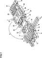
1 ist eine Perspektivansicht, die einen schematischen Aufbau einer Ausführungsform eines Draht-Halters gemäß der Erfindung zeigt. 2 ist eine Perspektivansicht eines Zustandes, in dem ein Halter-Hauptkörper und eine Halter-Abdeckung des in 1 gezeigten Draht-Halters 1 miteinander verbunden sind. 3 ist eine Draufsicht auf den Zustand, in dem ein Halter-Hauptkörper und eine Halter-Abdeckung des in 1 gezeigten Draht-Halters miteinander verbunden sind. 4A und 4B sind veranschaulichende Zeichnungen eines speziellen Beispiels einer Konstruktion zum Anbringen des in 2 gezeigten Draht-Halters an einer elektrischen Vorrichtung, wobei 4A eine Seitenansicht ist, die einen Zustand zeigt, in dem die Anbringung beginnt, und 4B eine Seitenansicht ist, die einen Zustand zeigt, in dem die Anbringung abgeschlossen ist. 5 ist eine Schnittansicht entlang der Linie A-A in 3. 6A und 6B sind vergrößerte Schnittansichten eines ersten Halteabschnitts des in 1 gezeigten Halter-Hauptkörpers, wobei 6A eine vergrößerte Schnittansicht zu einem Zeitpunkt ist, bevor ein Draht durch den ersten Halteabschnitt gehalten wird, und 6B eine vergrößerte Schnittansicht zu einem Zeitpunkt ist, zu dem der Draht durch den ersten Halteabschnitt gehalten wird. 7A und 7B sind vergrößerte Perspektivansichten eines zweiten Halteabschnitts des in 1 gezeigten Halter-Hauptkörpers, wobei 7A eine vergrößerte Perspektivansicht zu einem Zeitpunkt ist, bevor der Draht durch den zweiten Halteabschnitt gehalten wird, und 7B eine vergrößerte Perspektivansicht zu einem Zeitpunkt ist, zu dem der Draht durch den zweiten Halteabschnitt gehalten wird. 1 Fig. 10 is a perspective view showing a schematic structure of an embodiment of a wire holder according to the invention. 2 FIG. 15 is a perspective view of a state in which a holder main body and a holder cover of the FIG 1 shown wire holders 1 connected to each other. 3 FIG. 12 is a plan view of the state in which a holder main body and a holder cover of the FIG 1 shown wire holders are interconnected. 4A and 4B FIG. 4 are illustrative drawings of a specific example of a construction for mounting the in. FIG 2 shown wire holder on an electrical device, wherein 4A is a side view showing a state in which the attachment begins, and 4B is a side view showing a state in which the attachment is completed. 5 is a sectional view taken along the line AA in 3 , 6A and 6B are enlarged sectional views of a first holding portion of the in 1 shown holder main body, wherein 6A an enlarged sectional view at a time before a wire is held by the first holding portion, and 6B Fig. 10 is an enlarged sectional view at a time when the wire is held by the first holding portion. 7A and 7B FIG. 15 are enlarged perspective views of a second holding portion of FIG 1 shown holder main body, wherein 7A an enlarged perspective view at a time before the wire is held by the second holding portion, and 7B is an enlarged perspective view at a time when the wire is held by the second holding portion.

Ein Draht-Halter 1 der vorliegenden Ausführungsform enthält, wie in 1 gezeigt, einen Halter-Hauptkörper 5 mit einem Draht-Ausrichtabschnitt 11, der eine Vielzahl von Drähten 3, die einen Kabelbaum bilden, parallel hält, sowie eine Halter-Abdeckung 6, die integral an einer Abschlussseite des Halter-Hauptkörpers 5 ausgebildet ist.A wire holder 1 of the present embodiment, as shown in FIG 1 shown a holder main body 5 with a wire alignment section 11 that has a lot of wires 3 , which forms a harness, keeps parallel, as well as a holder cover 6 integral with a terminal side of the holder main body 5 is trained.

Des Weiteren ist die Halter-Abdeckung 6 über einen dünnen Gelenkabschnitt 7 drehbar mit der einen Endseite des Halter-Hauptkörpers 5 verbunden. Ein Pfeil B in 1 zeigt eine Richtung der Drehung der Halter-Abdeckung 6 über den dünnen Gelenkabschnitt 7.Furthermore, the holder cover 6 over a thin joint section 7 rotatably with the one end side of the holder main body 5 connected. An arrow B in 1 shows a direction of rotation of the holder cover 6 over the thin joint section 7 ,

Die Halter-Abdeckung 6 kann, wie in 2 und 3 gezeigt, um den dünnen Gelenkabschnitt 7 als einen Drehpunkt herum so gedreht werden, dass sie über dem Halter-Hauptkörper 5 angeordnet ist, so dass sie auf diese Weise auf den Halter-Hauptkörper 5 aufgesetzt ist.The holder cover 6 can, as in 2 and 3 shown around the thin hinge section 7 as a fulcrum to be turned over the holder main body 5 is arranged, so that they on the holder main body 5 is attached.

Um den Halter-Hauptkörper 5 und die Halter-Abdeckung 6 in diesem verbundenen Zustand aneinander zu arretieren, ist an dem Halter-Hauptkörper 5 ein Arretiervorsprung 12 an der anderen Abschlussseite integral ausgebildet, und des Weiteren sind elastische Arretierteile 13 integral an Positionen näher an dem einen Ende (näher an dem dünnen Gelenkabschnitt 7) so ausgebildet, dass sie sich davon nach oben erstrecken.Around the holder main body 5 and the holder cover 6 Locking to each other in this connected state is on the holder main body 5 a locking projection 12 formed integrally on the other end side, and further are elastic locking parts 13 integral at positions closer to the one end (closer to the thin hinge portion 7 ) are formed so as to extend upward therefrom.

Des Weiteren ist an der Halter-Abdeckung 6 ein elastisches Arretierteil 21 integral an einem Endabschnitt ausgebildet, der über dem anderen Endabschnitt des Halter-Hauptkörpers 5 angeordnet ist, wenn die Halter-Abdeckung 6 über dem Halter-Hauptkörper 5 positioniert ist, um mit dem Arretiervorsprung 12 in Eingriff zu kommen. Des Weiteren sind Verbindungs-Aussparungsabschnitte 23 in Abschnitten der Halter-Abdeckung 6 ausgebildet, die näher an dem dünnen Gelenkabschnitt 7 liegen, um mit den elastischen Arretierteilen 13 in Eingriff zu kommen.Furthermore, on the holder cover 6 an elastic locking part 21 formed integrally at one end portion that overlies the other end portion of the holder main body 5 is arranged when the holder cover 6 over the holder main body 5 is positioned to engage with the locking projection 12 to get in touch. Further, connection recess portions 23 in sections of the holder cover 6 formed closer to the thin hinge section 7 lie around with the elastic locking parts 13 to get in touch.

Des Weiteren sind bei dem Draht-Halter dieser Ausführungsform Anbringungs-Wellenabschnitte 24 an beiden äußeren Flächen der Halter-Abdeckung 6 an Positionen, die näher an dem dünnen Gelenkabschnitt 7 liegen, so vorhanden, dass sie davon vorstehen. Weiterhin sind Anbringungs-Eingriffsabschnitte 25 an beiden äußeren Flächen der Halter-Abdeckung 6 an Positionen, die näher an dem elastischen Arretierteil 21 liegen, so vorhanden, dass sie davon vorstehen.Further, in the wire holder of this embodiment, mounting shaft portions 24 on both outer surfaces of the holder cover 6 at positions closer to the thin hinge section 7 lie so available that they protrude from it. Further, attachment engaging portions 25 on both outer surfaces of the holder cover 6 at positions closer to the elastic locking part 21 lie so available that they protrude from it.

Diese Anbringungs-Wellenabschnitte 24 und die Anbringungs-Eingriffsabschnitte 25 sind, wie in 4A und 4B dargestellt, Abschnitte, die an der Seite eines Kabelbaum-Verbindungsabschnitts 9 arretiert werden, wenn der Draht-Halter 1 an dem Kabelbau-Verbindungsabschnitt 9 einer elektrischen Vorrichtung befestigt wird. Isolierungs-Trennschneiden 31 von Schneidklemm-Steckverbindungsanschlüssen sind an dem Kabelbaum-Verbindungsabschnitt 9 angeordnet, mit dem die Drähte 3 in dem Draht-Halter 1 über Schneidklemm-Steckverbindung elektrisch verbunden werden sollen.These mounting shaft sections 24 and the attachment engaging portions 25 are, as in 4A and 4B shown, portions on the side of a harness connecting portion 9 be locked when the wire holder 1 at the cable connection section 9 an electrical device is attached. Insulation separating knives 31 of insulation displacement connector terminals are on the harness connection portion 9 arranged with which the wires 3 in the wire holder 1 to be electrically connected via insulation displacement connector.

Die Anbringungs-Wellenabschnitte 24 des Draht-Halters 1 werden, wie in 4A gezeigt, von Wellen-Lagerungsabschnitten 33, die an dem Kabelbaum-Verbindungsabschnitt 9 vorhanden sind, drehbar gelagert. Die Anbringungs-Eingriffsabschnitte 25 werden, wie in 4B gezeigt, um die Anbringungs-Wellenabschnitte 24 als Drehpunkte herum so gedreht, dass sie mit Arretierabschnitten 35 in Eingriff gebracht werden, die an dem Kabelbaum-Verbindungsabschnitt 9 vorhanden sind, wenn die Schneidklemm-Steckverbindung durch die Isolierungs-Trennschneiden 31 abgeschlossen ist, so dass der Draht-Halter 1 an dem Kabelbaum-Verbindungsabschnitt 9 fixiert ist.The mounting shaft sections 24 of the wire holder 1 be like in 4A shown by shaft-bearing sections 33 attached to the harness connecting portion 9 are present, rotatably mounted. The attachment engaging portions 25 be like in 4B shown to the attachment shaft sections 24 turned around as fulcrums so that they have locking sections 35 engaged on the harness connecting portion 9 are present when the insulation displacement connector through the insulation separating cutters 31 is completed, leaving the wire holder 1 at the harness connecting portion 9 is fixed.

Die Halter-Abdeckung 6 des Draht-Halters 1 der vorliegenden Ausführungsform hält Abschnitte der Drähte 3, die aus dem Halter-Hauptkörper 5 heraus geführt werden (im Folgenden als herausgeführte Abschnitte bezeichnet) fest zwischen dem Halter-Hauptkörper 5 und der Abdeckung selbst, wie dies in 5 gezeigt ist, in einem Zustand, in dem die Halter-Abdeckung 6, wie in 2 und 3 gezeigt, auf den Halter-Hauptkörper aufgesetzt ist.The holder cover 6 of the wire holder 1 The present embodiment holds portions of the wires 3 coming out of the holder main body 5 out (hereinafter referred to as led out portions) firmly between the holder main body 5 and the cover itself, like this in 5 is shown in a state in which the holder cover 6 , as in 2 and 3 shown is placed on the holder main body.

Des Weiteren hält die Halter-Abdeckung 6 in einem Zustand, in dem sie auf den Halter-Hauptkörper 5 aufgesetzt ist, wie dies in 2 und 3 dargestellt ist, Abschnitte 3a der Drähte 3, die aus dem Halter-Hauptkörper 5 herausgeführt sind (die im Folgenden als herausgeführte Abschnitte bezeichnet werden), zwischen dem Halter-Hauptkörper 5 und der Abdeckung selbst, wie dies in 5 dargestellt ist.Furthermore, the holder cover holds 6 in a state in which they are on the holder main body 5 is set up, as in 2 and 3 is shown, sections 3a the wires 3 coming out of the holder main body 5 led out (hereinafter referred to as led out portions), between the holder main body 5 and the cover itself, like this in 5 is shown.

In 5 kennzeichnet Bezugszeichen 16 einen Halte-Wandabschnitt des Halter-Hauptkörpers 5, der von unten an den herausgeführten Abschnitten 3a anliegt. Des Weiteren kennzeichnet Bezugszeichen 26 einen Halte-Wandabschnitt an der Seite der Halter-Abdeckung 6, der von oben an den herausgeführten Abschnitten 3a anliegt und sie zwischen dem Halte-Wandabschnitt 16 und der Abdeckung selbst hält.In 5 denotes reference numeral 16 a holding wall portion of the holder main body 5 from the bottom to the led out sections 3a is applied. Furthermore, reference number denotes 26 a retaining wall portion on the side of the holder cover 6 from the top to the led out sections 3a rests and they between the retaining wall section 16 and the cover itself holds.

Der Draht-Ausrichtabschnitt 11 des Halter-Hauptkörpers 5 enthält in dieser Ausführungsform, wie in 5 gezeigt, eine Vielzahl von Vorderenden-Einführlöchern 14, Löcher 15 zum Einführen von Isolierungs-Trennschneiden, einen zweiten Halteabschnitt 18 sowie eine erste Draht-Tragerippe 19.The wire alignment section 11 of the holder main body 5 contains in this embodiment, as in 5 shown a variety of leading end insertion holes 14 , Holes 15 for inserting insulation cutters, a second holding section 18 and a first wire support rib 19 ,

Des Weiteren enthält die Halter-Abdeckung 6 eine erste Befestigungsrippe 27, die einem ersten Halteabschnitt 17 entspricht, eine zweite Befestigungsrippe 28, die dem zweiten Halteabschnitt 18 entspricht, und eine zweite Draht-Tragerippe 29, die der ersten Draht-Tragerippe 19 entspricht.Furthermore, the holder cover contains 6 a first fixing rib 27 which is a first holding section 17 corresponds to a second fastening rib 28 that the second holding section 18 corresponds, and a second wire support rib 29 that's the first wire support rib 19 equivalent.

Die Vielzahl von Vorderenden-Einführlöchern 14 sind in dem ersten Halteabschnitt 17, der rippenartig an dem Halter-Hauptkörper 5 vorsteht, so ausgebildet, dass sie parallel in konstanten Abschnitten durch ihn hindurch verlaufen. Die Vielzahl von Vorderenden-Einführlöchern 14 ermöglichen es, vordere Endabschnitte 3b der jeweiligen Drähte durch sie hindurch einzuführen und die Vielzahl von Drähten parallel zu positionieren.The variety of front end insertion holes 14 are in the first holding section 17 , which ribs on the holder main body 5 protrudes, so formed that they are parallel in constant sections pass through it. The variety of front end insertion holes 14 allow it, front end sections 3b insert the respective wires therethrough and to position the plurality of wires in parallel.

Bei der vorliegenden Ausführungsform ist, wie in 6A dargestellt, das Vorderenden-Einführloch 14 als ein sich verjüngendes Durchgangsloch ausgebildet, so dass D2 ≤ d ≤ D1 gilt, wobei D1 einen Innendurchmesser jedes der Vorderenden-Einführlöcher 14 an einer Draht-Einführseite bezeichnet, D2 einen Innendurchmesser jedes der Vorderenden-Einführlöcher an einer Draht-Ausführseite bezeichnet, und d einen Außendurchmesser einer Ummantelung jedes der Drähte bezeichnet.In the present embodiment, as in FIG 6A shown, the front end insertion hole 14 is formed as a tapered through hole such that D2 ≦ d ≦ D1, where D1 is an inner diameter of each of the leading end insertion holes 14 at a wire insertion side, D2 denotes an inner diameter of each of the leading end insertion holes at a wire delivery side, and d denotes an outer diameter of a sheath of each of the wires.

Die Löcher 15 zum Einführen von Isolierungs-Trennschneiden sind Öffnungen, die es ermöglichen, die Isolierungs-Trennschneiden 31 an den äußeren Schneidklemm-Steckverbindungsanschlüssen durch sie hindurch zur Schneidklemm-Steckverbindung mit den Drähten 3 einzuführen, die parallel in dem Draht-Halter 1 gehalten werden.The holes 15 for inserting insulation cutters are openings that allow the insulation cutters 31 at the outer insulation displacement connector terminals through it to the insulation displacement connector with the wires 3 Introduce the parallel in the wire holder 1 being held.

Der zweite Halteabschnitt 18 ist rippenartig in dem Draht-Ausrichtabschnitt 11 an einer Position vorhanden, an der der zweite Halteabschnitt 18 dem ersten Halteabschnitt 17 über die Löcher 15 zum Einführen von Isolierungs-Trennschneiden zugewandt ist.The second holding section 18 is ribbed in the wire alignment section 11 present at a position where the second holding portion 18 the first holding section 17 over the holes 15 for inserting insulation cutting edges.

Dieser zweite Halteabschnitt 18 bewirkt, wie in 7A und 7B gezeigt, parallele Positionierung der Vielzahl von Drähten mittels einer Vielzahl von Schlitzen 41, die die entsprechenden Drähte von Seiten derselben her einzeln einschließen.This second holding section 18 causes, as in 7A and 7B shown, parallel positioning of the plurality of wires by means of a plurality of slots 41 which individually enclose the respective wires from the sides thereof.

Jeder Schlitz 41 ist, wie in 7A und 7B gezeigt, in einer Form ausgebildet, für die W3 < W2 < d < W1 gilt, wobei W1 eine Spaltbreite jedes Schlitzes an einem offenen Ende bezeichnet, über das ein Draht eingeführt wird, W2 eine Spaltbreite an einer Draht-Trageposition (ein Abschlussende) bezeichnet, W3 eine Spaltbreite an einer Position zwischen dem offenen Ende und der Draht-Trageposition bezeichnet, und d den Außendurchmesser der Ummantelung jedes Drahtes 3 bezeichnet.Every slot 41 is how in 7A and 7B shown formed in a form for which W3 <W2 <d <W1, where W1 denotes a gap width of each slot at an open end through which a wire is inserted, W2 denotes a gap width at a wire carrying position (a terminal end) , W3 denotes a gap width at a position between the open end and the wire-carrying position, and d denotes the outer diameter of the sheath of each wire 3 designated.

Die erste Draht-Tragerippe 19 steht, wie in 5 gezeigt, an dem Halter-Hauptkörper so vor, dass sie Rückseiten der Drähte trägt, die parallel in dem Draht-Ausrichtabschnitt gehalten werden.The first wire support rib 19 stands, as in 5 as shown on the holder main body so as to support rear sides of the wires held in parallel in the wire aligning section.

Die erste Befestigungsrippe 27 steht an der Halter-Abdeckung 6 vor und befestigt ein oberes Ende des ersten Halteabschnitts 17, in dem die Vorderenden-Einführlöcher 14 ausgebildet sind, wie dies in 5 dargestellt ist, wenn die Halter-Abdeckung 6 auf den Halter-Hauptkörper 5 aufgesetzt ist.The first fixing rib 27 stands on the holder cover 6 before and attached to an upper end of the first holding portion 17 in which the front end insertion holes 14 are trained, as in 5 is shown when the holder cover 6 on the holder main body 5 is attached.

Die zweite Befestigungsrippe 28 steht an der Halter-Abdeckung 6 vor und befestigt ein oberes Ende des zweiten Halteabschnitts 18, in dem die Schlitze 41 ausgebildet sind, so dass die offenen Enden der Schlitze 41, wie in 5 gezeigt, verschlossen werden, wenn die Halter-Abdeckung 6 auf den Halter-Hauptkörper 5 aufgesetzt wird.The second fixing rib 28 stands on the holder cover 6 before and attaches an upper end of the second holding portion 18 in which the slots 41 are formed so that the open ends of the slots 41 , as in 5 Shown to be closed when the holder cover 6 on the holder main body 5 is put on.

Die zweite Draht-Tragerippe 29 steht an der Halter-Abdeckung 6 vor und schließt die Drähte 3 im Zusammenwirken mit der ersten Draht-Tragerippe 19, wie in 5 gezeigt, fest von oben und von unten ein, wenn die Halter-Abdeckung 6 auf den Halter-Hauptkörper 5 aufgesetzt ist, um so die Vielzahl von Drähten 3 parallel zu positionieren.The second wire support rib 29 stands on the holder cover 6 before and closes the wires 3 in cooperation with the first wire support rib 19 , as in 5 shown firmly from above and from below, when the holder cover 6 on the holder main body 5 is attached, so the variety of wires 3 position in parallel.

Bei dem Draht-Halter 1 der hier beschriebenen Ausführungsform werden, wenn der Draht-Halter 1 mit den vorderen Endabschnitten 3b der Vielzahl von Drähten verbunden wird, die den Kabelbaum bilden, zunächst, wie in 6A und 6B gezeigt, die vorderen Endabschnitte 3b der Drähte über die Vorderenden-Einführlöcher 14 eingeführt, die in dem Draht-Ausrichtabschnitt 11 des Halter-Hauptkörpers 5 ausgebildet sind, so dass die Vielzahl von Drähten 3 vorübergehend befestigt werden und dabei durch die Vorderenden-Einführlöcher 14 parallel gehalten werden.At the wire holder 1 of the embodiment described herein, when the wire holder 1 with the front end portions 3b the plurality of wires that make up the harness, at first, as in 6A and 6B shown the front end sections 3b the wires over the front end insertion holes 14 introduced in the wire alignment section 11 of the holder main body 5 are formed, so that the plurality of wires 3 be temporarily secured while passing through the front end insertion holes 14 be kept parallel.

Anschließend werden, wie in 7A und 7B gezeigt, die abgedeckten Drähte 3, die vorübergehend befestigt sind, in die entsprechenden Schlitze 41 in dem zweiten Halteabschnitt 18 eingeführt, so dass die abgedeckten Drähte 3 in dem Draht-Ausrichtabschnitt 11 durch die Vorderenden-Einführlöcher 14 und die Schlitze 41 parallel gehalten werden.Subsequently, as in 7A and 7B shown the covered wires 3 , which are temporarily fixed, in the corresponding slots 41 in the second holding section 18 introduced so that the covered wires 3 in the wire alignment section 11 through the front end insertion holes 14 and the slots 41 be kept parallel.

Dann wird mit dem Aufsetzen der Halter-Abdeckung 6 auf den Halter-Hauptkörper 5, wie in 5 gezeigt, die Verbindung des elektrischen Halters mit dem Kabelbaum abgeschlossen.Then the attachment of the holder cover 6 on the holder main body 5 , as in 5 shown, completed the connection of the electrical holder to the wiring harness.

Anschließend kann beim Vorgang des Verbindens des Draht-Halters 1 mit dem Kabelbaum der Vorgang des Einführens der vorderen Endabschnitte 3b der Drähte über die entsprechenden Vorderenden-Einführlöcher 14 außerordentlich einfach ausgeführt werden, da der Innendurchmesser D1 jedes der Vorderenden-Einführlöcher 14 an der Draht-Einführseite größer festgelegt ist als der Außendurchmesser d jeder der Ummantelungen der Drähte 3, so dass die vorderen Endabschnitte der Drähte nicht durch Öffnungsränder der Vorderenden-Einführlöcher 14 behindert werden und daher das Einführen über die entsprechenden Vorderenden-Einführlöcher 14 nicht erschwert wird und keine starke Betätigungskraft erforderlich ist. Des Weiteren passen, da der Innendurchmesser D2 jedes der Vorderenden-Einführlöcher 14 an der Draht-Ausführseite genauso groß ist wie oder kleiner als der Außendurchmesser d der Ummantelungen der Drähte 3, die vorderen Endabschnitte 3b der Drähte, die über die entsprechenden Vorderenden-Einführlöcher 14 eingeführt werden, eng anliegend an entsprechende Öffnungsränder der Vorderenden-Einführlöcher 14 an der Draht-Ausführseite, so dass verhindert wird, dass sie gelöst werden (nur vorübergehend befestigt werden). Daher kommt es nicht dazu, dass die Drähte 3 plötzlich aus dem Halter-Hauptkörper 5 gelöst werden oder die Drähte 3 in dem Halter-Hauptkörper 5 gelockert werden, wenn die Drähte 3 in die Schlitze 41 eingeführt werden oder die Halter-Abdeckung 6 auf den Halter-Hauptkörper 5 aufgesetzt wird, wenn die Vielzahl von Drähten 3 parallel in dem Halter-Hauptkörper 5 gehalten werden. Des Weiteren werden, wenn die Halter-Abdeckung 6 auf den Halter-Hauptkörper 5 aufgesetzt ist, die herausgeführten Abschnitte 3a der Drähte 3 fest zwischen dem Halter-Hauptkörper 5 und der Halter-Abdeckung 6 gehalten.Subsequently, during the process of connecting the wire holder 1 with the harness, the process of inserting the front end portions 3b the wires via the corresponding front end insertion holes 14 be made extremely simple, since the inner diameter D1 of each of the front end insertion holes 14 is set larger at the wire insertion side than the outer diameter d of each of the sheaths of the wires 3 such that the leading end portions of the wires are not penetrated by opening edges of the leading end insertion holes 14 be impeded and therefore the insertion of the corresponding front end insertion holes 14 is not complicated and no strong operating force is required. Further, since the inner diameter D2 of each of the front-end insertion holes 14 at the wire run page is as big as or smaller than the outer diameter d of the sheaths of the wires 3 , the front end sections 3b the wires coming through the corresponding front end insertion holes 14 are introduced, closely adjacent to corresponding opening edges of the front end insertion holes 14 at the wire-delivery side, so that it is prevented that they are released (only temporarily fixed). Therefore, it does not happen that the wires 3 suddenly out of the holder main body 5 be solved or the wires 3 in the holder main body 5 be loosened when the wires 3 in the slots 41 or the holder cover 6 on the holder main body 5 is put on when the variety of wires 3 parallel in the holder main body 5 being held. Furthermore, if the holder cover 6 on the holder main body 5 is attached, the led out sections 3a the wires 3 firmly between the holder main body 5 and the holder cover 6 held.

Daher kann bei dem Draht-Halter 1 der hier beschriebenen Ausführungsform der Zustand, in dem die Vielzahl von Drähten 3, die den Kabelbaum bilden, parallel gehalten werden, mit dem einfachen Vorgang hergestellt werden, ohne dass ein spezielles Werkzeug eingesetzt wird, und daher kann die Endbehandlung des Kabelbaums, bei der der Draht-Halter 1 mit den vorderen Endabschnitten 3b der Drähte des Kabelbaums verbunden wird, außerordentlich leicht ausgeführt werden.Therefore, in the wire holder 1 of the embodiment described here, the state in which the plurality of wires 3 , which make the wiring harness, are kept parallel, can be manufactured with the simple operation without the use of a special tool, and therefore can be the final treatment of the wiring harness in which the wire holder 1 with the front end portions 3b the wires of the wiring harness is connected, are made extremely easy.

Des Weiteren kann bei dem Draht-Halter 1 der hier beschriebenen Ausführungsform der Draht-Halter 1 mit geringer Betätigungskraft an dem Kabelbaum angebracht werden, ohne dass ein spezielles Werkzeug eingesetzt wird, und daher kann der Draht-Halter 1 selbst im Fertigungsbereich einfach an einem Kabelbaum angebracht werden.Furthermore, in the wire holder 1 the embodiment of the wire holder described here 1 be attached to the cable harness with little operating force without a special tool is used, and therefore the wire holder 1 even in the production area simply attached to a wiring harness.

Dann wird bei dem Kabelbaum, an dem der Draht-Halter 1 der hier beschriebenen Ausführungsform angebracht worden ist, wie in 4A und 4B gezeigt, der Draht-Halter 1 in dem Kabelbaum-Verbindungsabschnitt 9 der elektrischen Vorrichtung installiert, mit der der Kabelbaum verbunden werden soll, und die Isolierungs-Trennschneiden 31 der Schneidklemm-Steckverbindungsanschlüsse, die an dem Kabelbaum-Verbindungsabschnitt 9 angeordnet sind, werden über die Löcher 15 zum Einführen von Isolierungs-Trennschneiden in dem Draht-Halter 1 eingeführt, so dass die Drähte 3 in dem Draht-Halter 1 über Schneidklemm-Steckverbindung elektrisch mit den Schneidklemm-Steckverbindungsanschlüssen verbunden werden.Then, at the wiring harness to which the wire holder 1 the embodiment described here has been attached, as in 4A and 4B shown the wire holder 1 in the harness connecting portion 9 the electrical device to which the harness is to be connected, and the insulation cutters 31 the insulation displacement connector terminals connected to the harness connection portion 9 are placed over the holes 15 for inserting insulation cutters in the wire holder 1 introduced, so the wires 3 in the wire holder 1 be connected via insulation displacement connector electrically to the insulation displacement connector terminals.

Dabei werden von den Drähten 3 in dem Draht-Halter 1 die aus dem Halter-Hauptkörper 5 herausgeführten Abschnitte 3a fixiert, indem sie zwischen dem Halter-Hauptkörper 5 und der Halter-Abdeckung 6 gehalten werden, und die vorderen Endabschnitte 3b der Drähte werden enganliegend in die Vorderenden-Einführlöcher 14 eingeführt. Des Weiteren werden bei dem Draht-Halter 1 der Ausführungsform die Drähte 3 in dem Draht-Halter 1 fixiert, indem sie durch die Schlitze 41 von den Seiten gehalten werden, und sie werden darüber hinaus dadurch fixiert, dass sie durch die erste Draht-Tragerippe 19 und die zweite Draht-Tragerippe 29 von unten und von oben gehalten werden. So werden die Drähte 3 sicher in dem Draht-Halter 1 fixiert.It will be from the wires 3 in the wire holder 1 that from the holder main body 5 led out sections 3a fixed by placing it between the holder main body 5 and the holder cover 6 be held, and the front end sections 3b The wires are tightly fitted in the front end insertion holes 14 introduced. Furthermore, the wire holder 1 the embodiment of the wires 3 in the wire holder 1 fixed by passing through the slots 41 Moreover, they are held in place by the first wire support rib 19 and the second wire support rib 29 be kept from below and from above. This is how the wires become 3 safely in the wire holder 1 fixed.

Dadurch wird, wenn die Isolierungs-Trennschneiden 31 in Presskontakt mit den entsprechenden Drähten 3 gebracht werden, verhindert, dass die Drähte 3 von den Isolierungs-Trennschneiden 31 weggeschoben werden, so dass die Isolierungs-Trennschneiden 31 über Schneidklemm-Steckverbindung sicher in Presskontakt mit den Drähten 3 gebracht werden können, wie dies in 8 dargestellt ist.This will when the insulation cutters 31 in press contact with the corresponding wires 3 be brought, prevents the wires 3 from the insulation cutting edges 31 be pushed away so that the insulation cutting edges 31 via insulation displacement connector securely in press contact with the wires 3 can be brought, as in 8th is shown.

Des Weiteren weist bei dem Draht-Halter 1 der hier beschriebenen Ausführungsform der Draht-Halter 1 verglichen mit den herkömmlichen Schneidklemm-Steckverbindern eine geringere Anzahl an Einzelteilen auf und ist des Weiteren einfach aufgebaut.Furthermore, in the wire holder 1 the embodiment of the wire holder described here 1 Compared with the conventional insulation displacement connectors on a smaller number of parts and is also simple in construction.

Daher ermöglicht der Draht-Halter 1, wenn er anstelle eines Schneidklemm-Steckverbinders an dem Endabschnitt des Kabelbaums angebracht wird, die Endbehandlung des Kabelbaums, Verringerung der Herstellungskosten für den Kabelbaum, und Verbesserung der Zuverlässigkeit der Schneidklemm-Steckverbindung am Endabschnitt des Kabelbaums.Therefore, the wire holder allows 1 when mounted on the end portion of the wire harness instead of an insulation displacement connector, the end treatment of the wire harness, reduction of the manufacturing cost of the wire harness, and improvement of the reliability of the insulation displacement connector at the end portion of the wire harness.

Des Weiteren enthält bei dem Draht-Halter 1 der hier beschriebenen Ausführungsform die Halter-Abdeckung 6 die erste Befestigungsrippe 27, die das obere Ende des ersten Halteabschnitts 17, in dem die Vorderenden-Einführlöcher 14 ausgebildet sind, befestigt, wenn die Halter-Abdeckung 6 auf den Halter-Hauptkörper 5 aufgesetzt wird.Furthermore, the wire holder contains 1 the embodiment described here, the holder cover 6 the first fixing rib 27 , which is the upper end of the first holding section 17 in which the front end insertion holes 14 are formed, fastened when the holder cover 6 on the holder main body 5 is put on.

Dadurch wirkt eine Presskraft auf den ersten Halteabschnitt 17 des Halter-Hauptkörpers 5 von der ersten Befestigungsrippe 27 in einem Zustand, in dem die Halter-Abdeckung 6 auf den Halter-Hauptkörper aufgesetzt ist. Diese Presskraft wirkt in einer Richtung, in der die Vorderenden-Einführlöcher 14 zusammengedrückt werden, und daher kann die Kraft zum Halten der Drähte an den Vorderenden-Einführlöchern 14 verstärkt werden, so dass die Fixierung der Drähte in dem Draht-Halter 1 verstärkt werden kann.As a result, a pressing force acts on the first holding section 17 of the holder main body 5 from the first fixing rib 27 in a state where the holder cover 6 is placed on the holder main body. This pressing force acts in a direction in which the front end insertion holes 14 can be compressed, and therefore, the force for holding the wires at the front end insertion holes 14 be strengthened, allowing the fixation of the wires in the wire holder 1 can be strengthened.

Des Weiteren wird, wenn die Halter-Abdeckung 6 auf den Halter-Hauptkörper 5 aufgesetzt wird, die Kraft zum Halten der Drähte 3 an den Vorderenden-Einführlöchern 14 durch die erste Befestigungsrippe 27 verstärkt. So kann kommt es, selbst wenn ein Abschnitt des ersten Halteabschnitts 17, der sich oberhalb der Vorderenden-Einführlöcher 14 befindet, geringe Dicke erhält, so dass die Vorderenden-Einführlöcher 14 über elastische Verformung bezüglich des Durchmessers leicht aufgeweitet werden, wenn die Drähte 3 durch sie hindurch eingeführt werden, nicht dazu, dass die Leistungsfähigkeit der Vorderenden-Einführlöcher 14 beim Halten von Drähten verringert wird. Daher kann das Einführen der vorderen Endabschnitte 3b der Drähte über die Vorderenden-Einführlöcher 14 erleichtert werden, wenn die Dicke des Abschnitts des ersten Halteabschnitts 17 reduziert wird, der sich oberhalb der Vorderenden-Einführlöcher 14 befindet.Furthermore, if the holder cover 6 on the holder main body 5 is put on, the force to hold the wires 3 to the Tip-insertion holes 14 through the first fastening rib 27 strengthened. So it can happen, even if a section of the first holding section 17 that extends above the front end insertion holes 14 is located, gets small thickness, leaving the front end insertion holes 14 slightly widened over elastic deformation in diameter when the wires 3 are introduced through them, not to the performance of the front end insertion holes 14 is reduced when holding wires. Therefore, the insertion of the front end portions 3b the wires over the front end insertion holes 14 be facilitated when the thickness of the portion of the first holding portion 17 is reduced, which is above the front end insertion holes 14 located.

Des Weiteren enthält bei dem Draht-Halter 1 der hier beschriebenen Ausführungsform der Draht-Halter 1 den zweiten Halteabschnitt 18, der in dem Draht-Ausrichtabschnitt 11 an der Position vorhanden ist, an der der zweite Halteabschnitt 18 dem ersten Halteabschnitt 17 über die Löcher 15 zum Einführen von Isolierungs-Trennschneiden zugewandt ist, um die Vielzahl elektrischer Drähte 3 mittels der Schlitze 41 parallel zu positionieren, die die Drähte von ihren Seiten her einzeln einschließen, die erste Draht-Tragerippe 19, die an dem Halter-Hauptkörper 5 so vorsteht, dass sie die Rückseiten der Drähte 3 trägt, die parallel in dem Draht-Ausrichtabschnitt 11 gehalten werden, und die zweite Draht-Tragerippe 29, die an der Halter-Abdeckung 6 vorsteht, wobei die zweite Draht-Tragerippe 29 die Drähte 3 im Zusammenwirken mit der ersten Draht-Tragerippe 19 fest einschließt, wenn die Halter-Abdeckung 6 auf den Halter-Hauptkörper 5 aufgesetzt wird, um die Drähte 3 parallel zu positionieren.Furthermore, the wire holder contains 1 the embodiment of the wire holder described here 1 the second holding section 18 in the wire alignment section 11 is present at the position where the second holding portion 18 the first holding section 17 over the holes 15 for inserting insulation cutting edges to the plurality of electrical wires 3 by means of the slots 41 in parallel, which individually enclose the wires from their sides, the first wire support rib 19 attached to the holder main body 5 so protrudes that they are the backs of the wires 3 carries in parallel in the wire alignment section 11 be held, and the second wire support rib 29 attached to the holder cover 6 protrudes, with the second wire support rib 29 the wires 3 in cooperation with the first wire support rib 19 tightly encloses when the holder cover 6 on the holder main body 5 is attached to the wires 3 position in parallel.

Dadurch ist verglichen mit einem Fall, in dem das Fixieren der Drähte 3 in dem Draht-Halter 1 auf die zwei Positionen beschränkt ist, an denen die Drähte 3 zwischen dem Halte-Wandabschnitt 16 und dem Halte-Wandabschnitt 26 gehalten werden, und die vorderen Endabschnitte 3b der Drähte 3 enganliegend in die Vorderenden-Einführlöcher 1 passen, die Fixierung der Drähte in dem Draht-Halter 1 aufgrund der höheren Anzahl von Draht-Fixierpositionen in dem Draht-Halter 1 sehr stark.Thereby, as compared with a case where the fixing of the wires 3 in the wire holder 1 is limited to the two positions where the wires 3 between the retaining wall section 16 and the retaining wall portion 26 be held, and the front end sections 3b the wires 3 snugly into the front end insertion holes 1 fit, fixing the wires in the wire holder 1 due to the higher number of wire fixing positions in the wire holder 1 very strong.

Daher werden bei der Schneidklemm-Steckverbindung, wenn die Isolierungs-Trennschneiden 31 über die Löcher 15 zum Einführen von Isolierungs-Trennschneiden zum Presskontakt mit den Drähten 3 eingeführt werden, die Drähte 3 so stark fixiert, dass sie nicht von den Isolierungs-Trennschneiden 31 weggeschoben werden, wodurch es möglich wird, die Zuverlässigkeit bei der Schneidklemm-Steckverbindung zu verbessern.Therefore, in the insulation displacement connector, when the insulation cutters 31 over the holes 15 for inserting insulation cutting blades for press-contact with the wires 3 be inserted, the wires 3 so strongly fixed that they are not separated from the insulation 31 be pushed away, which makes it possible to improve the reliability of the insulation displacement connector.

Bei dem Draht-Halter 1 der hier beschriebenen Ausführungsform ist jeder Schlitz 41 in der Form ausgebildet, für die W3 < W2 < d < W1 gilt, wobei W1 die Spaltbreite jedes Schlitzes an einem offenen Ende bezeichnet, über das jeder Draht 3 eingeführt wird, W2 die Spaltbreite an einem Draht-Trageabschnitt (einem Abschlussende) bezeichnet, W3 die Spaltbreite an einer Position zwischen dem offenen Ende und der Draht-Trageposition bezeichnet und d den Außendurchmesser der Ummantelung jedes Drahtes 3 bezeichnet.At the wire holder 1 The embodiment described here is each slot 41 is formed in the form for which W3 <W2 <d <W1 where W1 denotes the gap width of each slot at an open end over which each wire passes 3 W2 denotes the gap width at a wire carrying portion (a terminal end), W3 denotes the gap width at a position between the open end and the wire carrying position, and d denotes the outer diameter of the sheath of each wire 3 designated.

Dadurch wird es schwierig, die Drähte 3 aus den Schlitzen 41 zu lösen, während der Vorgang des Eindrückens der Drähte in die Schlitze 41 in dem zweiten Halteabschnitt 18 erleichtert wird. Dadurch kann nicht nur die Installation der Drähte in dem Halter-Hauptkörper 5 erleichtert werden, sondern auch die Fixierung der Drähte in dem Draht-Halter 1 kann verstärkt werden.This will make the wires difficult 3 out of the slots 41 to solve while the process of pushing the wires into the slots 41 in the second holding section 18 is relieved. This can not only install the wires in the holder main body 5 be facilitated, but also the fixation of the wires in the wire holder 1 can be strengthened.

9 zeigt den Aufbau eines Draht-Halters 1a als ein Vergleichsbeispiel, und 10 zeigt einen Zustand nach der Ausführung einer Schneidklemm-Steckverbindung in dem Draht-Halter 1a. 9 shows the structure of a wire holder 1a as a comparative example, and 10 shows a state after the execution of a insulation displacement connector in the wire holder 1a ,

Bei dem in 9 gezeigten Draht-Halter 1a sind im Unterschied zu dem Draht-Halter 1 der Ausführungsform die Vorderenden-Einführlöcher 14 und die Schlitze 41, die in der Ausführungsform dargestellt sind, in dem Halter-Hauptkörper 5a nicht vorhanden. Dieser Halter-Hauptkörper 5a und die Halter-Abdeckung 6a des Vergleichsbeispiels enthalten Rippen 18a, 28a an einer Vielzahl von Positionen, die einander gegenüberliegen. Diese Befestigungsrippen 18a, 28a halten Drähte 3 von unten und von oben, so dass die Drähte 3 festgehalten werden.At the in 9 shown wire holder 1a are unlike the wire holder 1 the embodiment, the front end insertion holes 14 and the slots 41 in the embodiment shown in the holder main body 5a unavailable. This holder main body 5a and the holder cover 6a of Comparative Example contain ribs 18a . 28a at a plurality of positions facing each other. These fastening ribs 18a . 28a hold wires 3 from below and from above, leaving the wires 3 be held.

Bei dem wie oben beschrieben aufgebauten Draht-Halter 1a werden jedoch die Drähte 3 an dem Halter-Hauptkörper 5a gelockert, wenn die Halter-Abdeckung 6a auf den Halter-Hauptkörper 5a aufgesetzt wird, und wenn ein Schneidklemm-Steckverbindungsvorgang durchgeführt wird, werden die Drähte 3, wie in 10 gezeigt, von den Isolierungs-Trennschneiden 31 weggeschoben, so dass zu befürchten ist, dass eine Schneidklemm-Steckverbindung fehlerhaft ist. Des Weiteren werden aufgrund der Stärke der Fixierung der Drähte 3 in dem Draht-Halter 1 die Drähte 3 aufgrund von Presskräften bewegt, die durch Isolierungs-Trennschneiden 31 ausgeübt werden, so dass zu befürchten ist, dass eine Schneidklemm-Steckverbindung fehlerhaft ist.In the wire holder constructed as described above 1a however, the wires become 3 on the holder main body 5a loosened when the holder cover 6a on the holder main body 5a is put on, and when a insulation displacement connection operation is performed, the wires 3 , as in 10 shown by the insulation cutting edges 31 pushed away, so it is to be feared that a insulation displacement connector is defective. Furthermore, due to the strength of the fixation of the wires 3 in the wire holder 1 the wires 3 moved due to pressing forces caused by insulation cutting edges 31 be exercised so that it is to be feared that a insulation displacement connector is defective.

Das bei diesem Vergleichsbeispiel auftretende Problem, dass die Drähte 3 in dem Draht-Halter 1a gelockert werden, wenn die Halter-Abdeckung 6 auf den Halter-Hauptkörper 5a aufgesetzt wird, kann gelöst werden, wenn der Draht-Halter 1a die Vorderenden-Einführlöcher 14 und den Halte-Wandabschnitt 16 sowie den Halte-Wandabschnitt 26 gemäß der Erfindung enthält, da der Halte-Wandabschnitt 16 und der Halte-Wandabschnitt 26 beim Halten der herausgeführten Abschnitte 3a der Drähte 3 zusammenwirken.The problem occurring in this comparative example that the wires 3 in the wire holder 1a be loosened when the holder cover 6 on the holder main body 5a can be solved when the wire holder 1a the front end insertion holes 14 and the retaining wall section 16 and the retaining wall section 26 According to the invention, since the retaining wall section 16 and the retaining wall section 26 while holding the led out sections 3a the wires 3 interact.

Das heißt, die Drähte in dem Draht-Halter werden nicht gelockert, wenn die Halter-Abdeckung 6 auf den Halter-Hauptkörper 5 aufgesetzt wird und dabei eine Spannung auf die Drähte 3 ausgeübt wird, durch die die Drähte 3 in einem gedehnten Zustand gehalten werden, wenn die vorderen Endabschnitte 3b der Drähte 3 in den Vorderenden-Einführlöchern 14 gehalten werden. So kann fehlerhafte Schneidklemm-Steckverbindung aufgrund von Lockerung der Drähte in dem Draht-Halter vermieden werden.That is, the wires in the wire holder are not loosened when the holder cover 6 on the holder main body 5 is put on while doing a tension on the wires 3 is exercised through which the wires 3 be kept in a stretched state when the front end portions 3b the wires 3 in the front end insertion holes 14 being held. Thus, faulty insulation displacement connector can be avoided due to loosening of the wires in the wire holder.

Es wird daher erwogen, dem Draht-Halter gemäß der Erfindung einen einfacheren Aufbau zu verleihen, bei dem die erste Befestigungsrippe und der zweite Halteabschnitt weggelassen werden und die Vielzahl von Drähten durch die Schlitze parallel positioniert werden.It is therefore considered to give the wire holder according to the invention a simpler structure in which the first fixing rib and the second holding portion are omitted and the plurality of wires are positioned in parallel through the slots.

Die Erfindung ist nicht auf die oben beschriebene Ausführungsform beschränkt, sondern kann, wenn erforderlich, ohne Einschränkungen abgewandelt und verbessert werden. Des Weiteren kommen die Materialien, Formen, Abmessungen, numerischen Werte, Ausformungen, Anzahl, Anordnungsposition der einzelnen Bestandteile beliebig gewählt werden und sind nicht auf die in der Ausführungsform beschriebenen beschränkt, sofern die Erfindung mit ihnen umgesetzt werden kann.The invention is not limited to the above-described embodiment, but can be modified and improved as required without limitations. Further, the materials, shapes, dimensions, numerical values, shapes, number, arrangement position of the individual components come to be arbitrary, and are not limited to those described in the embodiment as far as the invention can be implemented with them.

Beispielsweise ist die Form des Vorderenden-Einführlochs 14 nicht auf die in der Ausführungsform beschriebene Kreisform beschränkt und kann rechteckig sein. In diesem Fall kann ein Abschnitt, der sich oberhalb der Löcher befindet, so ausgebildet sein, dass seine Dicke gering ist, so dass die Vorderenden-Einführlöcher leicht verformt werden.For example, the shape of the leading end insertion hole 14 not limited to the circular shape described in the embodiment, and may be rectangular. In this case, a portion located above the holes may be formed so that its thickness is small, so that the front end insertion holes are easily deformed.

Obwohl die Erfindung ausführlich und unter Bezugnahme auf die spezielle Ausführungsform beschrieben worden ist, ist für den Fachmann, für den die Erfindung relevant ist, klar, dass verschiedene Veränderungen oder Abwandlungen daran vorgenommen werden können, ohne vom Geist und von Schutzumfang der Erfindung abzuweichen.Although the invention has been described in detail and with reference to the specific embodiment, it will be apparent to those skilled in the art to which the invention pertains that various changes or modifications may be made thereto without departing from the spirit and scope of the invention.

Die vorliegende Patentanmeldung basiert auf der japanischen Patentanmeldung (Nr. 2009-273398) , eingereicht am 1. Dezember 2009, deren Inhalt hiermit durch Verweis einbezogen wird.The present patent application is based on Japanese Patent Application (No. 2009-273398) , filed on Dec. 1, 2009, the contents of which are hereby incorporated by reference.

Industrielle EinsetzbarkeitIndustrial applicability

Bei dem erfindungsgemäßen Draht-Halter weist der Draht-Halter verglichen mit den herkömmlichen Schneidklemm-Steckverbindern eine geringere Anzahl an Einzelteilen auf und ist darüber hinaus einfach aufgebaut. Des Weiteren kann der Draht-Halter mit geringer Betätigungskraft einfach an dem Kabelbaum angebracht werden.In the wire holder of the present invention, the wire holder has a smaller number of parts as compared with the conventional insulation displacement connectors and is also simple in structure. Further, the low-force-force wire holder can be easily attached to the harness.

Darüber hinaus können die Drähte in dem Draht-Halter sicher fixiert werden, indem die vorderen Endabschnitte der Drähte fest in die Vorderenden-Einführlöcher eingeführt werden, und des Weiteren können die aus dem Halter-Hauptkörper herausgeführten Abschnitte der Drähte zwischen dem Halter-Hauptkörper und der Halter-Abdeckung gehalten werden. Dadurch kommt es, wenn die Isolierungs-Trennschneiden die Schneidklemm-Steckverbindungsanschlüsse, die an dem Kabelbaum-Verbindungsabschnitt der elektrischen Vorrichtung angebracht werden, mit der der Kabelbaum verbunden werden soll, über die Löcher zum Einführen der Isolierungs-Trennschneiden eingeführt werden, nicht dazu, dass die Drähte von den Isolierungs-Trennschneiden weggeschoben werden, weil sich die Drähte gelockert haben, so dass die Drähte bei der Schneidklemm-Steckverbindung in Presskontakt mit den Isolierungs-Trennschneiden gebracht werden können.Moreover, the wires in the wire holder can be securely fixed by inserting the front end portions of the wires firmly into the front end insertion holes, and further, the portions of the wires led out of the holder main body can be interposed between the holder main body and the holder Holder cover are kept. As a result, when the insulation cutters insert the insulation displacement connector terminals to be attached to the harness connecting portion of the electric device to which the wire harness is to be inserted through the holes for inserting the insulation cutters, it does not occur the wires are pushed away from the insulation cutters because the wires have loosened so that the wires in the insulation displacement connector can be brought into press contact with the insulation cutters.

So kann der Draht-Halter der Erfindung, wenn er am Endabschnitt des Kabelbaums anstelle eines herkömmlichen Schneidklemm-Steckverbinders angebracht wird, die Endbehandlung des Kabelbaums erleichtern, um so die Herstellungskosten für den Kabelbaum zu reduzieren, und kann die Zuverlässigkeit bei der Gewährleistung von Schneidklemm-Steckverbindung am Ende des Kabelbaums verbessern.Thus, the wire holder of the invention, when attached to the end portion of the wire harness in place of a conventional insulation displacement type connector, can facilitate the finishing of the wire harness so as to reduce the manufacturing cost of the wire harness, and can improve reliability in ensuring insulation displacement. Improve connector at the end of the wiring harness.

BezugszeichenlisteLIST OF REFERENCE NUMBERS

11
Draht-Halter;Wire holder;
33
Draht;Wire;
3a3a
herausgeführte Abschnitte (herausgeführter Abschnitt);led out sections (led out section);
3b3b
vorderer Endabschnitt von Draht;front end portion of wire;
55
Halter-Hauptkörper;Holder main body;
66
Halter-Abdeckung;Holder cover;
77
dünner Gelenkabschnitt;thin joint section;
99
Kabelbaum-Verbindungsabschnitt;Wire harness connection portion;
1111
Draht-Ausrichtabschnitt;Wire alignment section;
1414
Vorderenden-Einführloch;Tip-insertion hole;
1515
Loch zum Einführen von Isolierungs-Trennschneide;Hole for inserting insulation cutting edge;
1616
Halte-Wandabschnitt;Retaining wall section;
1717
erster Halteabschnitt;first holding section;
1818
zweiter Halteabschnitt;second holding section;
1919
erste Draht-Tragerippe;first wire support rib;
2424
Anbringungs-Wellenabschnitt;Attachment shaft portion;
2525
Anbringungs-Eingriffsabschnitt;Attachment-engaging portion;
2626
Halte-Wandabschnitt;Retaining wall section;
2727
erste Befestigungsrippe;first fixing rib;
2828
zweite Befestigungsrippe;second fixing rib;
29 29
zweite Draht-Tragerippe;second wire support rib;
3131
Isolierungs-Trennschneide;Insulation cutting blade;
3535
Arretierabschnitt;lock portion;
4141
Schlitz;Slot;
D1D1
Innendurchmesser von Vorderenden-Einführloch an Draht-Einführseite;Inner diameter of front end insertion hole on wire insertion side;
D2D2
Innendurchmesser von Vorderenden-Isolierloch an Draht-Ausführseite;Inner diameter of front-end insulation hole on wire-extension side;
dd
Außendurchmesser von Ummantelung von Draht;Outer diameter of sheath of wire;
W1W1
Spaltbreite von Schlitz am offenen Ende;Gap width of slot at the open end;
W2W2
Spaltbreite von Schlitz an Draht-Trageposition; undGap width from slot to wire carrying position; and
W3W3
Spaltbreite von Schlitz an Position zwischen offenem Ende und Draht-TragepositionSlit width from slot to position between open end and wire carrying position

ZITATE ENTHALTEN IN DER BESCHREIBUNG QUOTES INCLUDE IN THE DESCRIPTION

Diese Liste der vom Anmelder aufgeführten Dokumente wurde automatisiert erzeugt und ist ausschließlich zur besseren Information des Lesers aufgenommen. Die Liste ist nicht Bestandteil der deutschen Patent- bzw. Gebrauchsmusteranmeldung. Das DPMA übernimmt keinerlei Haftung für etwaige Fehler oder Auslassungen.This list of the documents listed by the applicant has been generated automatically and is included solely for the better information of the reader. The list is not part of the German patent or utility model application. The DPMA assumes no liability for any errors or omissions.

Zitierte PatentliteraturCited patent literature

  • JP 08-083631 A [0006] JP 08-083631 A [0006]
  • JP 2001-135368 A [0006] JP 2001-135368 A [0006]
  • JP 2009-273398 [0087] JP 2009-273398 [0087]

Claims (4)

Draht-Halter, der umfasst: einen Halter-Hauptkörper, der einen Draht-Ausrichtabschnitt aufweist, der eine Vielzahl von Drähten, die einen Kabelbaum bilden, parallel hält, sowie eine Halter-Abdeckung, die auf den Halter-Hauptkörper aufgesetzt ist, um so die in dem Halter-Hauptkörper gehaltenen Drähte von oben abzudecken, so dass Abschnitte der Drähte, die aus dem Halter-Hauptkörper herausgeführt werden, fest zwischen dem Halter-Haltkörper und der Halter-Abdeckung gehalten werden, wobei der Draht-Ausrichtabschnitt mit einer Vielzahl von Vorderenden-Einführlöchern, über die vordere Endabschnitte der Drähte so eingeführt werden, dass die Drähte parallel positioniert werden, sowie mit einem Loch zum Einführen einer Isolierungs-Trennschneide versehen ist, über die eine Isolierungs-Trennschneide so eingeführt wird, dass die parallel gehaltenen Drähte in Presskontakt mit der Isolierungs-Trennschneide gebracht werden, und wobei jedes der Vorderenden-Einführlöcher als ein sich verjüngendes Durchgangsloch ausgebildet sind, für das D2 ≤ d < D1 gilt, wobei D1 einen Innendurchmesser jedes der Vorderenden-Einführlöcher an einer Draht-Einführseite bezeichnet, D2 einen Innendurchmesser jedes der Vorderenden-Einführlöcher an einer Draht-Ausführseite bezeichnet und d einen Außendurchmesser eine Ummantelung jedes der Drähte bezeichnet.Wire holder, which includes: a holder main body having a wire aligning portion that holds a plurality of wires constituting a wire harness in parallel, and a holder cover mounted on the holder main body so as to hold the ones held in the holder main body Cover wires from above so that portions of the wires led out of the holder main body are firmly held between the holder holding body and the holder cover, the wire aligning portion having a plurality of front end insertion holes, via the front End portions of the wires are inserted so that the wires are positioned in parallel, as well as provided with a hole for inserting an insulation cutting edge over which an insulation cutting edge is inserted so that the wires held in parallel brought into pressing contact with the insulation cutting edge and each of the leading end insertion holes being a tapered passage where D1 denotes an inner diameter of each of the front-end insertion holes on a wire insertion side, D2 denotes an inner diameter of each of the front-end insertion holes on a wire-delivery side, and d an outer diameter one sheath of each called the wires. Draht-Halter nach Anspruch 1, wobei der Draht-Halter mit einer ersten Befestigungsrippe versehen ist, die ein oberes Ende eines ersten Halteabschnitts befestigt, in dem die Vorderenden-Einführlöcher ausgebildet sind, wenn die Halter-Abdeckung auf den Halter-Hauptkörper aufgesetzt ist.The wire holder according to claim 1, wherein the wire holder is provided with a first fixing rib which fixes an upper end of a first holding portion in which the front end insertion holes are formed when the holder cover is fitted on the holder main body. Draht-Halter nach Anspruch 1 oder 2, der umfasst: einen zweiten Halteabschnitt, der in dem Draht-Ausrichtabschnitt an einer Position vorhanden ist, an der der zweite Halteabschnitt dem ersten Halteabschnitt über das Loch zum Einführen der Isolierungs-Trennschneide zugewandt ist, wobei der zweite Halteabschnitt die Drähte parallel zu Schlitzen halt, die die Drähte einzeln von ihren Seiten her einschließen; eine erste Draht-Tragerippe, die an dem Halter-Hauptkörper so vorsteht, dass sie Rückseiten der in dem Draht-Ausrichtabschnitt parallel gehaltenen Drähte trägt, sowie eine zweite Draht-Tragerippe, die an der Halter-Abdeckung vorsteht, wobei die zweite Draht-Tragerippe die Drähte im Zusammenwirken mit der ersten Draht-Tragerippe fest einschließt, wenn die Halter-Abdeckung auf den Halter-Hauptkörper aufgesetzt ist, um die Drähte parallel zu positionieren.A wire holder according to claim 1 or 2, comprising: a second holding portion provided in the wire aligning portion at a position where the second holding portion faces the first holding portion via the insulating-cutting-blade insertion hole, the second holding portion holding the wires in parallel with slots containing the wires to include individually from their sides; a first wire support rib projecting on the holder main body so as to support rear sides of the wires held in parallel in the wire alignment section, and a second wire support rib projecting on the holder cover, the second wire support rib tightly enclosing the wires in cooperation with the first wire support rib when the holder cover is mounted on the holder main body to position the wires in parallel. Draht-Halter nach Anspruch 3, wobei jeder der Schlitze in einer Form ausgebildet ist, für die W3 < W2 < d < W1 gilt, wobei W1 eine Spaltbreite jedes der Schlitze an einem offenen Ende bezeichnet, über die jeder der Drähte eingeschoben wird, W2 eine Spaltbreite an einer Draht-Trageposition bezeichnet, W3 eine Spaltbreite an einer Position zwischen dem offenen Ende und der Draht-Trageposition bezeichnet, und d den Außendurchmesser der Ummantelung jedes der Drähte bezeichnet.The wire holder according to claim 3, wherein each of the slots is formed in a shape to which W3 <W2 <d <W1, where W1 denotes a gap width of each of the slots at an open end over which each of the wires is inserted, W2 denotes a gap width at a wire carrying position, W3 denotes a gap width at a position between the open end and the wire carrying position, and d denotes the outer diameter of the sheath of each of the wires.
DE112010004634T 2009-12-01 2010-11-30 Wire Holder Withdrawn DE112010004634T5 (en)

Applications Claiming Priority (3)

Application Number Priority Date Filing Date Title
JP2009273398A JP2011119059A (en) 2009-12-01 2009-12-01 Wire holder
JP2009-273398 2009-12-01
PCT/JP2010/071373 WO2011068099A1 (en) 2009-12-01 2010-11-30 Wire holder

Publications (1)

Publication Number Publication Date
DE112010004634T5 true DE112010004634T5 (en) 2012-11-29

Family

ID=44114946

Family Applications (1)

Application Number Title Priority Date Filing Date
DE112010004634T Withdrawn DE112010004634T5 (en) 2009-12-01 2010-11-30 Wire Holder

Country Status (6)

Country Link
US (1) US20120037402A1 (en)
JP (1) JP2011119059A (en)
KR (1) KR20120045064A (en)
CN (1) CN102714362A (en)
DE (1) DE112010004634T5 (en)
WO (1) WO2011068099A1 (en)

Families Citing this family (17)

* Cited by examiner, † Cited by third party
Publication number Priority date Publication date Assignee Title
JP2012038714A (en) * 2010-07-14 2012-02-23 Yazaki Corp Pressure-welding connection apparatus and lighting device
JP5735781B2 (en) * 2010-11-24 2015-06-17 矢崎総業株式会社 Wire harness clamp
JP2013192344A (en) * 2012-03-13 2013-09-26 Yazaki Corp Housing for indoor illumination lamp for automobile and its electric wire holder
JP2013191405A (en) * 2012-03-14 2013-09-26 Yazaki Corp Electric wire holding structure
JP2015005422A (en) * 2013-06-21 2015-01-08 矢崎総業株式会社 connector
US9837759B2 (en) * 2013-06-25 2017-12-05 GE Lighting Solutions, LLC Wirestrain relief to use on a light emitting diode linear module
JP6045074B2 (en) * 2013-09-17 2016-12-14 矢崎総業株式会社 Electrical junction box
US12113344B2 (en) * 2015-08-24 2024-10-08 Sticnstac Llc Releasable holder for cables and conduit
US20190267785A1 (en) 2015-08-24 2019-08-29 Sticnstac, LLC Releasable holder for cables and conduit
JP6551216B2 (en) * 2015-12-18 2019-07-31 住友電装株式会社 Clip device
JP6352973B2 (en) 2016-05-31 2018-07-04 矢崎総業株式会社 Wire harness manufacturing method and manufacturing apparatus
KR101961043B1 (en) 2017-11-14 2019-03-21 주식회사 현대케피코 Holder for resistance welding
JP7330036B2 (en) * 2019-09-26 2023-08-21 日本航空電子工業株式会社 connector
JP7522639B2 (en) * 2020-11-09 2024-07-25 日本航空電子工業株式会社 connector
JP7810573B2 (en) * 2022-02-17 2026-02-03 矢崎総業株式会社 Wire harness
CN115215149A (en) * 2022-06-02 2022-10-21 四川秦巴电气有限责任公司 Wire holder and wire holding method
CN121769536A (en) * 2024-09-29 2026-03-31 泰科电子(上海)有限公司 Electrical connectors, electrical connection modules and connectors

Citations (3)

* Cited by examiner, † Cited by third party
Publication number Priority date Publication date Assignee Title
JPH0883631A (en) 1994-09-14 1996-03-26 Yazaki Corp Insulation displacement connector
JP2001135368A (en) 1999-10-29 2001-05-18 Fujikura Ltd Housing for crimp joint terminal and joint connector using the same
JP2009273398A (en) 2008-05-14 2009-11-26 Unitika Ltd Method for producing l-arabinose by acid hydrolysis

Family Cites Families (22)

* Cited by examiner, † Cited by third party
Publication number Priority date Publication date Assignee Title
FR2413807A1 (en) * 1977-12-30 1979-07-27 Socapex OPTICALLY CONTROLLED CONNECTOR FOR TABLECLOTH CABLE
JPS5864078U (en) * 1981-10-26 1983-04-30 星電器製造株式会社 IDC connector
GB8606654D0 (en) * 1986-03-18 1986-04-23 Molex Inc Multiconductor connector
US4826455A (en) * 1988-06-20 1989-05-02 Switchcraft, Inc. Terminal contact assembly
JPH0719089Y2 (en) * 1989-04-28 1995-05-01 株式会社白山製作所 Connector with slit terminal
US4995827A (en) * 1990-07-16 1991-02-26 Itt Corporation Strain relief IDC connector
US5586905A (en) * 1993-11-01 1996-12-24 Molex Incorporated Insulation displacement electrical connector with improved strain relief
US5549484A (en) * 1995-01-04 1996-08-27 Eric-Cambridge Co., Ltd. Electric terminal device
JP2938780B2 (en) * 1995-02-20 1999-08-25 サンクス株式会社 Parallel multi-core cable interconnection connector
JP3097819B2 (en) * 1995-07-04 2000-10-10 矢崎総業株式会社 Pressure welding joint connector and method of assembling wire harness using the same
US5820404A (en) * 1995-07-10 1998-10-13 Sumitomo Wiring Systems, Ltd. Terminal and cramping connector
JP3483990B2 (en) * 1995-07-24 2004-01-06 本多通信工業株式会社 IDC connector
JP3158035B2 (en) * 1996-01-22 2001-04-23 矢崎総業株式会社 ID connector
JP3013164B2 (en) * 1997-05-22 2000-02-28 株式会社ニチフ端子工業 connector
JP3346340B2 (en) * 1999-05-24 2002-11-18 住友電装株式会社 Fixed structure of case body and cover
JP2001015184A (en) * 1999-06-30 2001-01-19 Harness Syst Tech Res Ltd ID terminal
JP2002124312A (en) * 2000-10-13 2002-04-26 Yazaki Corp Auxiliary module and method of manufacturing the same
JP3948526B2 (en) * 2003-05-06 2007-07-25 矢崎総業株式会社 IDC connector
JP4100319B2 (en) * 2003-10-08 2008-06-11 住友電装株式会社 Splice absorption structure for automobile
JP2005149935A (en) * 2003-11-17 2005-06-09 Fujikura Ltd IDC joint connector
JP4273327B2 (en) * 2004-01-29 2009-06-03 オムロン株式会社 Connector for cable connection
JP4895725B2 (en) * 2006-08-25 2012-03-14 スリーエム イノベイティブ プロパティズ カンパニー IDC connector

Patent Citations (3)

* Cited by examiner, † Cited by third party
Publication number Priority date Publication date Assignee Title
JPH0883631A (en) 1994-09-14 1996-03-26 Yazaki Corp Insulation displacement connector
JP2001135368A (en) 1999-10-29 2001-05-18 Fujikura Ltd Housing for crimp joint terminal and joint connector using the same
JP2009273398A (en) 2008-05-14 2009-11-26 Unitika Ltd Method for producing l-arabinose by acid hydrolysis

Also Published As

Publication number Publication date
JP2011119059A (en) 2011-06-16
KR20120045064A (en) 2012-05-08
CN102714362A (en) 2012-10-03
WO2011068099A1 (en) 2011-06-09
US20120037402A1 (en) 2012-02-16

Similar Documents

Publication Publication Date Title
DE112010004634T5 (en) Wire Holder
DE19500959C2 (en) Electrical connector
DE69808730T2 (en) METHOD FOR CLOSING AN ELECTRIC FLAT CABLE AND CONNECTOR THEREFOR
DE69508569T2 (en) SECONDARY INTERLOCKING ELEMENT
EP2764591B1 (en) Cable feedthrough and method for assembling a cable feedthrough
EP3235067B1 (en) Plug and method to produce this plug
DE102009016756B4 (en) shield connector
DE102016206833B4 (en) Mat sealing cover of a waterproof connector
DE10354286A1 (en) Connector with shielding shell
EP3127194B1 (en) Multipole electric plug connector part
DE19919599C2 (en) Clamp with low insertion force and high holding force
DE3318248A1 (en) MULTIPOLE ELECTRICAL PLUG, IN PARTICULAR ROUND PLUG
DE102005036857A1 (en) Overmolded, sealed wire feedthrough
DE102016225598A1 (en) Energy storage device
WO2005112201A1 (en) Plug connector and method for the preassembly thereof
DE69609449T2 (en) Connector for flat cables
EP0844694B1 (en) Clamping device
EP2837062B1 (en) Connection holder for connecting a shielding of at least one coaxial line
DE102023114384A1 (en) Protective sleeve assembly and wiring harness
DE102015205209A1 (en) Connecting device, in particular for the automotive industry, for connecting end pieces of electrical lines with electrical connection contacts
DE102017216587B4 (en) connectors, cover and wiring harness
DE102020203702A1 (en) ELECTRICAL CONNECTION BOX
DE69928878T2 (en) Safety connection device, in particular for modular electrical devices
EP3837740B1 (en) Plug connector
EP1720222B1 (en) Electrical connector, particularly for airbag ignition systems

Legal Events

Date Code Title Description
R012 Request for examination validly filed
R079 Amendment of ipc main class

Free format text: PREVIOUS MAIN CLASS: H01R0004700000

Ipc: H01R0004240000

R119 Application deemed withdrawn, or ip right lapsed, due to non-payment of renewal fee