DE102019120226A1 - Valve and device for regulating pressures of a fluid with the valve and device for securing the valve in the transmission component - Google Patents
Valve and device for regulating pressures of a fluid with the valve and device for securing the valve in the transmission component Download PDFInfo
- Publication number
- DE102019120226A1 DE102019120226A1 DE102019120226.4A DE102019120226A DE102019120226A1 DE 102019120226 A1 DE102019120226 A1 DE 102019120226A1 DE 102019120226 A DE102019120226 A DE 102019120226A DE 102019120226 A1 DE102019120226 A1 DE 102019120226A1
- Authority
- DE
- Germany
- Prior art keywords
- valve
- opening
- section
- piston
- ring
- Prior art date
- Legal status (The legal status is an assumption and is not a legal conclusion. Google has not performed a legal analysis and makes no representation as to the accuracy of the status listed.)
- Ceased
Links
- 230000005540 biological transmission Effects 0.000 title claims abstract description 30
- 239000012530 fluid Substances 0.000 title claims abstract description 23
- 230000001105 regulatory effect Effects 0.000 title claims description 6
- 238000003825 pressing Methods 0.000 abstract description 2
- 238000004519 manufacturing process Methods 0.000 description 13
- 230000007704 transition Effects 0.000 description 9
- 229910052751 metal Inorganic materials 0.000 description 7
- 239000002184 metal Substances 0.000 description 7
- 239000000463 material Substances 0.000 description 6
- 238000007789 sealing Methods 0.000 description 5
- 230000000694 effects Effects 0.000 description 4
- 238000009434 installation Methods 0.000 description 4
- 241001295925 Gegenes Species 0.000 description 3
- 229910000831 Steel Inorganic materials 0.000 description 3
- 210000003746 feather Anatomy 0.000 description 3
- 239000010959 steel Substances 0.000 description 3
- 238000006073 displacement reaction Methods 0.000 description 2
- 238000003754 machining Methods 0.000 description 2
- 238000000034 method Methods 0.000 description 2
- 239000007787 solid Substances 0.000 description 2
- 238000003466 welding Methods 0.000 description 2
- BUHVIAUBTBOHAG-FOYDDCNASA-N (2r,3r,4s,5r)-2-[6-[[2-(3,5-dimethoxyphenyl)-2-(2-methylphenyl)ethyl]amino]purin-9-yl]-5-(hydroxymethyl)oxolane-3,4-diol Chemical compound COC1=CC(OC)=CC(C(CNC=2C=3N=CN(C=3N=CN=2)[C@H]2[C@@H]([C@H](O)[C@@H](CO)O2)O)C=2C(=CC=CC=2)C)=C1 BUHVIAUBTBOHAG-FOYDDCNASA-N 0.000 description 1
- 229910000838 Al alloy Inorganic materials 0.000 description 1
- 238000000576 coating method Methods 0.000 description 1
- 230000006835 compression Effects 0.000 description 1
- 238000007906 compression Methods 0.000 description 1
- 238000005520 cutting process Methods 0.000 description 1
- 238000004049 embossing Methods 0.000 description 1
- 238000005516 engineering process Methods 0.000 description 1
- 239000007769 metal material Substances 0.000 description 1
- 238000002360 preparation method Methods 0.000 description 1
- 210000000515 tooth Anatomy 0.000 description 1
- 238000007514 turning Methods 0.000 description 1
Images



Classifications
-
- F—MECHANICAL ENGINEERING; LIGHTING; HEATING; WEAPONS; BLASTING
- F16—ENGINEERING ELEMENTS AND UNITS; GENERAL MEASURES FOR PRODUCING AND MAINTAINING EFFECTIVE FUNCTIONING OF MACHINES OR INSTALLATIONS; THERMAL INSULATION IN GENERAL
- F16K—VALVES; TAPS; COCKS; ACTUATING-FLOATS; DEVICES FOR VENTING OR AERATING
- F16K15/00—Check valves
- F16K15/02—Check valves with guided rigid valve members
- F16K15/025—Check valves with guided rigid valve members the valve being loaded by a spring
-
- F—MECHANICAL ENGINEERING; LIGHTING; HEATING; WEAPONS; BLASTING
- F16—ENGINEERING ELEMENTS AND UNITS; GENERAL MEASURES FOR PRODUCING AND MAINTAINING EFFECTIVE FUNCTIONING OF MACHINES OR INSTALLATIONS; THERMAL INSULATION IN GENERAL
- F16K—VALVES; TAPS; COCKS; ACTUATING-FLOATS; DEVICES FOR VENTING OR AERATING
- F16K27/00—Construction of housing; Use of materials therefor
- F16K27/02—Construction of housing; Use of materials therefor of lift valves
- F16K27/0209—Check valves or pivoted valves
Landscapes
- Engineering & Computer Science (AREA)
- General Engineering & Computer Science (AREA)
- Mechanical Engineering (AREA)
- Safety Valves (AREA)
Abstract
Die Erfindung betrifft ein Ventil (20) mit einem Ventilgehäuse (2), wenigstens einem Kolben (3) mit den Merkmalen:- der Kolben (3) und das Ventilgehäuse (2) sind zueinander koaxial auf einer gedachten Ventilachse (6) angeordnet, wobei die Ventilachse (6) in eine erste axiale Richtung sowie in eine zur ersten axialen Richtung entgegengesetzte zweite axiale Richtung axial ausgerichtet ist,- der Kolben (3) ist axial beweglich in dem Ventilgehäuse (2) aufgenommen,- eine für Strömungsmittel durchlässige erste Öffnung (8) des Ventilgehäuses (2) ist koaxial zur Ventilachse (6) in dem Ventilgehäuse (2) ausgebildet, dem Kolben (7) axial zugewandt und durch den Kolben (3) verschließbar.Die Erfindung betrifft außerdem eine Vorrichtung (37) zur Regelung von Drücken eines Strömungsmittels in einem Fahrzeuggetriebe sowie eine Vorrichtung zur Sicherung eines Druckausgleichsventils (1) in dem Getriebebauteil (44).The invention relates to a valve (20) with a valve housing (2), at least one piston (3) with the features: the piston (3) and the valve housing (2) are arranged coaxially to one another on an imaginary valve axis (6), whereby the valve axis (6) is axially aligned in a first axial direction and in a second axial direction opposite to the first axial direction, - the piston (3) is accommodated in the valve housing (2) so that it can move axially, - a first opening that is permeable to fluid ( 8) of the valve housing (2) is formed coaxially to the valve axis (6) in the valve housing (2), facing the piston (7) axially and can be closed by the piston (3). The invention also relates to a device (37) for controlling Pressing a fluid in a vehicle transmission and a device for securing a pressure compensation valve (1) in the transmission component (44).
Description
Gebiet der ErfindungField of the Invention
Die Erfindung betrifft ein Ventil mit einem Ventilgehäuse, wenigstens einem Kolben, und zumindest einer Feder, mit den Merkmalen:
- - der Kolben und das Ventilgehäuse sind zueinander koaxial auf einer gedachten Ventilachse angeordnet, wobei die Ventilachse in eine erste axiale Richtung sowie in eine zur ersten axialen Richtung entgegengesetzte zweite axiale Richtung axial ausgerichtet ist,
- - der Kolben ist gegen Federkräfte der Feder axial beweglich in dem Ventilgehäuse aufgenommen,
- - eine für Strömungsmittel durchlässige erste Öffnung des Ventilgehäuses ist dem Kolben zugewandt und durch den Kolben verschließbar.
- the piston and the valve housing are arranged coaxially to one another on an imaginary valve axis, the valve axis being axially aligned in a first axial direction and in a second axial direction opposite to the first axial direction,
- the piston is accommodated in the valve housing so as to be axially movable against spring forces of the spring,
- - A first opening of the valve housing permeable to fluid faces the piston and can be closed by the piston.
Die Erfindung betrifft außerdem eine Vorrichtung zur Regelung von Drücken eines Strömungsmittels in einem Fahrzeuggetriebe mit dem Ventil und eine Vorrichtung zur Sicherung des Ventils in einem Bauteil des FahrzeuggetriebesThe invention also relates to a device for regulating pressures of a fluid in a vehicle transmission with the valve and a device for securing the valve in a component of the vehicle transmission
Hintergrund der ErfindungBackground of the Invention
Ventile der Gattung werden auf unterschiedlichste Weise im Gehäuse gesichert.
Beschreibung der ErfindungDescription of the invention
Die Aufgabe der Erfindung ist es, ein Ventil zu schaffen, mit dem die zuvor genannten Nachteile vermieden werden und durch welches die genannten Anforderungen mit einfachen und kostengünstigen Maßnahmen umgesetzt werden können.The object of the invention is to provide a valve with which the aforementioned disadvantages are avoided and through which the requirements mentioned can be implemented with simple and inexpensive measures.
Die Aufgabe ist mit einem Ventil nach dem Gegenstand des Anspruchs 1 gelöst. Außerdem ist eine erfindungsgemäße Vorrichtung mit einem Ventil vorgesehen.The object is achieved with a valve according to the subject matter of
An der ersten Öffnung sitzt wenigstens ein Ring. Der Ring ist koaxial zur ersten Öffnung angeordnet, d. h., seine Symmetrieachse ist koaxial zur Ventilachse. Der Ring ist separat zum Ventilgehäuse ausgebildet und
- A. gegen ein Verdrehen des Ventilgehäuses um die Ventilachse gegenüber dem Ring und/oder
- B. über einen Formschluß gegen ein Verdrehen des Rings gegenüber dem Ventilgehäuse
- A. against rotation of the valve housing about the valve axis relative to the ring and / or
- B. via a positive connection against rotation of the ring relative to the valve housing
Die Formschlussverbindung ist lösbar oder unlösbar. Und nach Definition ist der Formschluß durch einen an einer Innenkontur der ersten Öffnung ausgebildeten ersten Abschnitt und durch einen an einer Außenkontur des Ringes ausgebildeten zweiten Abschnitt gebildet. Dieser Formschluss sichert gegen ein Verdrehen um die Ventilachse, weil der erste Abschnitt und der zweite Abschnitt in radialer Richtung, d.h., quer zur Ventilachse gerichtet, aneinander abgestützt sind und damit in tangentialen Umfangsrichtung nicht gegeneinander verdrehbar sind.The positive connection is detachable or non-detachable. And by definition, the positive connection is formed by a first section formed on an inner contour of the first opening and by a second section formed on an outer contour of the ring. This form-fit locks against rotation about the valve axis because the first section and the second section are supported against one another in the radial direction, i.e., directed transversely to the valve axis, and therefore cannot be rotated relative to one another in the tangential circumferential direction.
Der Vorteil der Erfindung liegt darin, dass eine Verdrehsicherung oder eine Vorrichtung zur lageorientierten Montage des Ventils separat zu dem Ventilgehäuse ausgebildet werden kann. Das Ventilgehäuse kann ohne Änderungen für verschiedene Anwendungen vorgesehen sein. In diesem Falle muss lediglich der Ring an eventuell sich unterscheidende Anforderungen der Anwendung angepasst werden.The advantage of the invention is that an anti-rotation device or a device for position-oriented mounting of the valve can be formed separately from the valve housing. The valve housing can be provided for various applications without changes. In this case, the ring only has to be adapted to any different application requirements.
Der Vorteil aus A ergibt sich, dass der Ring beispielsweise gegen axiales verschieben und Verdrehen um seine Symmetrieachse an einem Gehäuse oder anderem Bauteil festgelegt wird und damit auch das Ventilgehäuse bzw. das Ventil gegen die Verdrehung um die Ventilachse oder axiale Verschiebung an dem Gehäuse festgelegt sein kann.The advantage of A arises that the ring is fixed, for example, against axial displacement and rotation about its axis of symmetry on a housing or other component, and thus the valve housing or the valve against the rotation about the valve axis or axial displacement is also fixed on the housing can.
Der Vorteil aus B ergibt sich insbesondere als Montagehilfe dann, wenn der Ring eine Markierung, Formschlusselement oder anderen Vorsprung aufweist, über die/den bei der Montage des Ventils akkurat die Position der Öffnungen des Ventils zweifelsfrei der Position der Kanäle des Bauteils oder Gehäuses zugeordnet werden kann. The advantage of B results in particular as an assembly aid if the ring has a marking, form-locking element or other projection, by means of which the position of the openings of the valve can be unambiguously assigned to the position of the channels of the component or housing when the valve is installed can.
Ein weiterer Vorteil ergibt sich daraus, dass über den Ring zum Beispiel der Querschnitt einer Öffnung des Ventilgehäuses geregelt werden kann, ohne dass dies direkte Auswirkungen auf das Design des Ventilgehäuses hat. Der Ring mit großem Innendurchmesser gewährt große Öffnungsquerschnitte der Ring mit kleinen Innendurchmesser oder einer Blende kann als Drossel wirken. Über die Auslegung des Rings kann dann ohne Änderung am Ventil der Einlass- oder Auslassquerschnitt einer Ventilöffnung beliebig vergrößert oder gedrosselt werden. Ein weiterer Vorteil ergibt sich daraus, dass an dem Ring auch ein Ventilsitz im Sinne einer Anlagefläche für den Kolben des Ventils geschaffen werden kann und dieser auf Anwendungen bezogen nur durch Änderungen am Ring oder durch Änderungen des Rings variiert werden kann.Another advantage results from the fact that the ring can be used, for example, to regulate the cross section of an opening of the valve housing without this having a direct effect on the design of the valve housing. The ring with a large inner diameter allows large opening cross-sections. The ring with a small inner diameter or an orifice can act as a throttle. By designing the ring, the inlet or outlet cross section of a valve opening can then be enlarged or throttled as desired without changing the valve. Another advantage results from the fact that a valve seat in the sense of a contact surface for the piston of the valve can also be created on the ring and this can be varied in relation to applications only by changes to the ring or by changes to the ring.
Die Ausführung des Ventilgehäuses kann in allen zuvor geschilderten Fällen dadurch vorteilhaft im Sinne größerer Stückzahlen bei der Fertigung vereinheitlicht werden. Werkzeug und Teilekosten bei der Herstellung können durch größere Fertigungslose reduziert werden.In all the cases described above, the design of the valve housing can advantageously be standardized in the sense of larger quantities during manufacture. Tool and part costs during production can be reduced through larger production lots.
Eine Ausgestaltung der Erfindung sieht vor, dass erste Abschnitt der Formschlussverbindung und der zweite Abschnitt der Formschlussverbindung jeweils durch wenigstens eine Fläche gebildet sind. Die Abschnitte sind über die Flächen aneinander abgestützt sind und liegen vorzugsweise großflächig im direkten Kontakt aneinander an. Der Vorteil dieser Ausgestaltung liegt darin, dass derartige Flächen in einfacher Weise durch Stanzen oder Prägen in den bestehenden Fertigungsprozess integriert werden können, ohne dass dies Einfluss auf die Herstellungskosten oder die Werkzeugkosten des Ventils hat. Dies insbesondere, wenn der Ring und das Ventilgehäuse aus Stahlblech gezogen, gestanzt und/oder geprägt werden.An embodiment of the invention provides that the first section of the positive connection and the second section of the positive connection are each formed by at least one surface. The sections are supported on one another via the surfaces and are preferably in direct contact with one another over a large area. The advantage of this embodiment is that such surfaces can be easily integrated into the existing manufacturing process by stamping or embossing, without this having an impact on the manufacturing costs or the tool costs of the valve. This is particularly the case when the ring and the valve housing are drawn, stamped and / or embossed from sheet steel.
Eine Ausgestaltung der Erfindung sieht vor, dass die Abschnitte tangential zu einer Umfangsrichtung um die Ventilachse zueinander ausgerichtet sind. Die Abschnitte verlaufen wahlweise als Kante bzw. als Fläche geradlinigen tangentialer Richtung, sodass sich große Stützbreiten ergeben, an denen der Ring gegen Verdrehung gegenüber dem Ventilgehäuse und umgekehrt abgestützt ist.One embodiment of the invention provides that the sections are aligned with one another tangentially to a circumferential direction about the valve axis. The sections run either as an edge or as a surface in a straight tangential direction, so that there are large support widths on which the ring is supported against rotation relative to the valve housing and vice versa.
Es ist mit einer Ausgestaltung der Erfindung vorgesehen, dass der Ring an der ersten Öffnung formschlüssig unlösbar befestigt ist. Die Verbindung zwischen dem Ring und dem Ventilgehäuse weist also keinen Stoffschluss auf. Der Ring weist wenigstens einen quer zur Ventilachse gerichteten radialen Vorsprung auf. Der Vorsprung kann beispielsweise in einer Formschlussverbindung beim späteren Einbau in ein Fahrzeuggetriebe zur Lageorientierung und/oder zur Lagesicherung bzw. Verdrehsicherungselement des Ventils eingesetzt werden. Das Verdrehsicherungselement kann vorteilhaft als Einzelteil hergestellt und dann formschlüssig am Ventilgehäuse befestigt werden. Es ist zum Beispiel dadurch möglich, die Lage und Orientierung des Vorsprungs und damit die Lage einer Verdrehsicherung des Ventils gegenüber einem Gehäuse bzw. Getriebebauteil an die spezifischen Besonderheiten sich unterscheidende Einbausituationen anzupassen. Das Ventil oder das Ventilgehäuse selbst braucht diesbezüglich nicht an die geänderte Einbausituation angepasst werden. Ein einheitliches Design des Ventils bzw. Ventilgehäuses kann dadurch für verschiedene Anwendungsfälle und Lageorientierungen verwendet werden. Die Fertigung des Ventilgehäuses kann in größeren Losen und damit kostengünstig vorgenommen werden. Die relativ hohen Werkzeugkosten zur Herstellung des Ventilgehäuses müssen nur einmal aufgebracht werden. Es sind im Bedarfsfall lediglich das Verdrehsicherungselement an die Anwendung anzupassen oder eine andere Orientierung des Verdrehsicherungselements bzw. Vorsprungs eines für mehrere Anwendungen verwendbaren Verdrehsicherungselements am Ventil erforderlich. Für den Ring notwendige Werkzeuge können kostengünstig und einfach auch für die Herstellung von geringen Losgrößen gestaltet werden. Durch eine entsprechende Wahl der Formschlussverbindung kann der Vorsprung in beliebigen Positionen um die Ventilachse am Ventilgehäuse befestigt werden. Die unlösbare Formschlussverbindung sichert eine solide um die Ventilachse bzw. auf dem Ventilgehäuse in Umfangsrichtung nicht verdrehbare Halterung ab. Über die unlösbare Formschlussverbindung können das Ventilgehäuse und der Ring miteinander verschnappt, ineinander eingehakt oder über plastische Verformung entweder des Ringes und/oder von Bereichen des Ventilgehäuses ineinandergreifend aneinander befestigt werden. Dabei ist nicht ausgeschlossen, dass eine Kraft-Formschluss-Verbindung ausgebildet ist.It is provided with an embodiment of the invention that the ring is non-detachably attached to the first opening. The connection between the ring and the valve housing therefore has no material connection. The ring has at least one radial projection directed transversely to the valve axis. The projection can be used, for example, in a positive connection during later installation in a vehicle transmission for positional orientation and / or for securing the position or securing the valve against rotation. The anti-rotation element can advantageously be produced as an individual part and then attached to the valve housing in a form-fitting manner. This makes it possible, for example, to adapt the position and orientation of the protrusion and thus the position of the valve to prevent rotation relative to a housing or gear component to the specific characteristics of the different installation situations. In this regard, the valve or the valve housing itself does not need to be adapted to the changed installation situation. A uniform design of the valve or valve housing can thus be used for different applications and orientation. The valve housing can be manufactured in larger lots and thus inexpensively. The relatively high tool costs for the manufacture of the valve housing need only be applied once. If necessary, only the anti-rotation element must be adapted to the application, or a different orientation of the anti-rotation element or projection of an anti-rotation element on the valve that can be used for several applications is required. Tools required for the ring can also be designed inexpensively and simply for the production of small lot sizes. The projection can be attached to the valve housing in any position about the valve axis by a corresponding choice of the form-fitting connection. The non-detachable positive connection ensures a solid holder that cannot be rotated around the valve axis or on the valve housing in the circumferential direction. Via the non-detachable positive connection, the valve housing and the ring can be snapped together, hooked into one another or fastened to one another by plastic deformation of either the ring and / or areas of the valve housing. It is not excluded that a force-positive connection is formed.
Unter Verdrehsicherung ist eine Sicherung zu verstehen, durch die der Sitz des Ventils in einem Gehäuse Position genau gewahrt wird. Dabei wird mit der Formschlussverbindung ein Verdrehen des Ventils um die eigene Ventilachse und/oder das Wandern in axialer Richtung in der Bohrung des Gehäuses verhindert.An anti-rotation lock is to be understood as a lock by which the valve is seated exactly in a housing position. The positive connection prevents the valve from rotating about its own valve axis and / or from wandering in the axial direction in the bore of the housing.
Eine Ausgestaltung der Erfindung sieht vor, dass der Vorsprung zumindest teilweise in radialer Richtung über eine Außenkontur des Ventilgehäuses hinausragt.
Der über das Ventilgehäuse hinausstehende Vorsprung greift zum Beispiel, wenn das Ventil in axial endseitig in einem Sackloch oder einer Gehäuseschulter abgestützt ist, als Verdrehsicherung formschlüssig in eine Ausnehmung oder Nut am Boden des Sackloches oder in eine entsprechende Ausnehmung der Gehäuseschulter ein.An embodiment of the invention provides that the projection is at least partially radial Direction protrudes beyond an outer contour of the valve housing.
The protrusion projecting beyond the valve housing engages, for example, if the valve is supported axially at the end in a blind hole or a housing shoulder, in a form-locking manner in a recess or groove at the bottom of the blind hole or in a corresponding recess of the housing shoulder.
Eine Ausgestaltung der Erfindung sieht vor, dass der Ring wenigstens einen ringförmigen Grundkörper aufweist. Von dem Grundkörper steht dann zum Beispiel der Vorsprung ab, wobei nicht ausgeschlossen ist, dass der Ring mehr als einen Vorsprung aufweist. Der ringförmige Grundkörper des Ringes greift in die erste Öffnung axial ein und hintergreift dabei einen Rand der ersten Öffnung axial an mindestens einer Stelle. Auf diese Weise ist der Ring zumindest in eine axiale Richtung gesichert, da der Rand einen axialen Hinterschnitt bildet. Die jeweilige Kontur des Ringes ragt dabei in radialer Richtung über den Öffnungsquerschnitt der ersten Öffnung hinaus. Der Ring ist auf diese Weise je nach Verwendung von wenigstens einem oder zwei Hinterschnitten in axiale Richtung unverrückbar gehalten.One embodiment of the invention provides that the ring has at least one annular base body. The protrusion then protrudes from the base body, for example, it being possible that the ring has more than one protrusion. The ring-shaped base body of the ring engages axially in the first opening and axially engages behind an edge of the first opening at at least one point. In this way, the ring is secured at least in an axial direction, since the edge forms an axial undercut. The respective contour of the ring protrudes in the radial direction beyond the opening cross section of the first opening. The ring is immovably held in this way depending on the use of at least one or two undercuts in the axial direction.
Eine Ausgestaltung der Erfindung sieht vor, dass der Rand einen integral mit dem Ventilgehäuse ausgebildeten hohlzylindrischen Abschnitt aufweist, welcher die erste Öffnung umgibt. Die Gestaltung des hohlzylindrischen Abschnitts bietet mehr Möglichkeiten, die Formschlussverbindung zu gestalten. Eine bevorzugte Ausführung sieht vor, dass der hohlzylindrischen Abschnitt im Durchmesser gegenüber dem Außendurchmesser des Ventils radial abgesetzt ist, d. h., dass ein erster Außendurchmesser des hohlzylindrischen Abschnitts kleiner als ein zweiter Außendurchmesser der außen zylindrischen Außenkontur des Ventilgehäuses und größer als ein erster Innendurchmesser der Öffnung des hohlzylindrischen Abschnitts und/oder der ersten Öffnung ist. Eine derartige Anordnung macht es möglich, den Grundkörper des Ringes formschlüssig auf den Ventilkörper aufzusetzen, ohne dass dieser radial über die Außenkontur des Ventilgehäuses hinausragt.One embodiment of the invention provides that the edge has a hollow cylindrical section which is formed integrally with the valve housing and which surrounds the first opening. The design of the hollow cylindrical section offers more options for designing the positive connection. A preferred embodiment provides that the diameter of the hollow cylindrical section is radially offset from the outside diameter of the valve, i. that is, a first outer diameter of the hollow cylindrical section is smaller than a second outer diameter of the outer cylindrical outer contour of the valve housing and larger than a first inner diameter of the opening of the hollow cylindrical section and / or the first opening. Such an arrangement makes it possible to positively place the base body of the ring on the valve body without the latter projecting radially beyond the outer contour of the valve housing.
Eine weitere Ausgestaltung der Erfindung sieht im vorgenannten Sinne vor, dass ein zweiter Innendurchmesser des zumindest innen um die Ventilachse rotationssymmetrisch ausgebildeten Grundkörpers kleiner ist als der erste Innendurchmesser der ersten Öffnung und/oder des hohlzylindrischen Abschnitts. Mit anderen Worten: die erste Öffnung ist im Durchmesser so gestaltet, dass der Ring in die erste Öffnung eingesetzt werden kann. Der Sitz des Ringes beansprucht radial nach außen hin weniger Platz, da der Grundkörper des Ringes innerhalb der Öffnung und/oder des hohlzylindrischen Abschnitts befestigt bzw. in diese eingesetzt ist.A further embodiment of the invention provides, in the aforementioned sense, that a second inner diameter of the base body, which is at least internally rotationally symmetrical about the valve axis, is smaller than the first inner diameter of the first opening and / or of the hollow cylindrical section. In other words, the diameter of the first opening is such that the ring can be inserted into the first opening. The seat of the ring takes up less space radially towards the outside, since the base body of the ring is fastened within the opening and / or the hollow cylindrical section or is inserted into the latter.
Mit einer weiteren Ausgestaltung der Erfindung ist vorgesehen, dass an dem Grundkörper ein erster Kragen und ein zweiter Kragen ausgebildet sind. Der erste Kragen ist radial nach außen von der Ventilachse weg gerichtet und kann zum Beispiel durch plastisches Umformen eines Rohr- oder Flachblechrohlings des Ringes in diese Richtung umgelegt werden. Außerdem ist der Kragen mit dem Vorsprung versehen, der für eine formschlüssige Lagesicherung des Ventils erforderlich ist. Der zweite Kragen ist radial nach außen von der Ventilachse weg gerichtet und hintergreift dabei den Rand im Inneren des Ventils axial - also an der anderen, d. h., im Inneren des Ventils liegenden Seite der ersten Öffnung. Der Ring ist so auf einfache Weise formschlüssig am Rand der ersten Öffnung in beide axiale Richtungen gehalten. Die Kragen werden vorzugsweise durch plastisches Umformen von einem Rohling des Ringes, welcher bevorzugt aus Stahlblech hergestellt ist, erzeugt. Alternativ ist die Verdrehsicherung nur lose formschlüssig in das Ventilgehäuse eingesetzt und die Verdrehsicherung ist über einen tangentialen Anschlag des Grundkörpers bzw. eines der Kragen am Ventilgehäuse abgesichert.Another embodiment of the invention provides that a first collar and a second collar are formed on the base body. The first collar is directed radially outward away from the valve axis and can be folded over in this direction, for example, by plastic forming of a tube or flat sheet metal blank of the ring. In addition, the collar is provided with the projection, which is required for a positive locking of the valve. The second collar is directed radially outward away from the valve axis and axially engages behind the edge inside the valve - that is to say on the other, i. that is, the inside of the valve side of the first opening. The ring is thus held in a simple, positive manner at the edge of the first opening in both axial directions. The collars are preferably produced by plastic deformation of a blank of the ring, which is preferably made from sheet steel. As an alternative, the anti-rotation lock is only inserted loosely in the valve housing and the anti-rotation lock is secured by a tangential stop on the base body or one of the collars on the valve housing.
Eine weitere Ausgestaltung der Erfindung sieht vor, dass am Rand der ersten Öffnung ein Ventilsitz ausgebildet ist, wobei die erste Öffnung durch den an dem Ventilsitz anliegenden Kolben verschließbar ist. Unter Ventilsitz ist ein zumindest zeitweise dichtender Anschlag des Kolbens in der Nähe der ersten Öffnung, also beispielsweise einer Einlassöffnung des Ventils, zu verstehen. Der Ventilsitz ist eine mit einer Geometrie einer Kante oder Fläche des Kolbens dichtend korrespondierende Ringfläche. Die Ringfläche ist zum Beispiel an dem Ring, zum Beispiel bevorzugt an dem zweiten Kragen, ausgebildet. Das hat den Vorteil, dass auch Dichtsitze an unterschiedliche Anwendungen angepasst variabel gestaltet werden können, ohne dass das Grunddesign des Ventilgehäuses und damit dessen Fertigung von der Art des Dichtsitzes beeinflusst wird. Es sind größere Losgrößen des Ventilgehäuses herstellbar. Die Herstellung ist damit kostengünstig. Eine bevorzugte Ausgestaltung der Erfindung sieht alternativ dazu vor, dass der Ventilsitz direkt an dem Material des Ventilgehäuses ausgebildet ist. Das Ventilgehäuse kann als Press- und/oder Ziehteil kostengünstig aus Blech hergestellt werden. Der Werkstoff des Blechs ist bevorzugt Stahl. Die Ausbildung des Ventilsitzes kann dabei ohne zusätzlichen Aufwand in den Press- bzw. Ziehprozess integriert werden.A further embodiment of the invention provides that a valve seat is formed at the edge of the first opening, the first opening being closable by the piston abutting the valve seat. A valve seat is to be understood as an at least temporarily sealing stop of the piston in the vicinity of the first opening, that is to say, for example, an inlet opening of the valve. The valve seat is an annular surface that sealingly corresponds to the geometry of an edge or surface of the piston. The ring surface is, for example, formed on the ring, for example preferably on the second collar. This has the advantage that sealing seats can also be designed to suit different applications without the basic design of the valve housing and thus its manufacture being influenced by the type of sealing seat. Larger batch sizes of the valve housing can be produced. The production is therefore inexpensive. A preferred embodiment of the invention alternatively provides that the valve seat is formed directly on the material of the valve housing. The valve housing can be manufactured inexpensively from sheet metal as a pressed and / or drawn part. The material of the sheet is preferably steel. The design of the valve seat can be integrated into the pressing or drawing process without additional effort.
Eine weitere Ausgestaltung der Erfindung sieht vor, dass in dem Ventilgehäuse eine für die Strömungsmittel durchlässige zweite Öffnung ausgebildet ist. Die zweite Öffnung ist zumindest teilweise durch den Kolben verschließbar. Die Ventilachse verläuft in die axialen Richtungen durch die erste Öffnung, d. h., die erste Öffnung ist axial ausgerichtet. Die zweite Öffnung ist radial von der Ventilachse entfernt. Der Vorsprung ragt radial über das Ventilgehäuse hinaus, wobei radial quer zur Ventilachse gerichtet ist.A further embodiment of the invention provides that a second opening which is permeable to the fluids is formed in the valve housing. The second opening can be at least partially closed by the piston. The valve axis extends in the axial directions through the first opening, ie the first opening is axially aligned. The second opening is located radially from the valve axis. The projection protrudes radially beyond the valve housing, being directed radially transversely to the valve axis.
Die Erfindung sieht in diesem Zusammenhang eine Vorrichtung zur Regelung von Drücken eines Strömungsmittels in einem Fahrzeuggetriebe vor. Die Vorrichtung ist aus einem Abschnitt eines Getriebebauteils, aus zumindest einem ersten Kanal und einem zweiten Kanal sowie aus dem Ventil gebildet und weist außerdem eine Vorrichtung zur Sicherung des Ventils bzw. zur lageorientierten Montage in dem Getriebebauteil auf. Der erste Kanal führt in dem Abschnitt des Getriebebauteils zu der ersten Öffnung und die zweite Öffnung mündet in den zweiten Kanal. Die Vorrichtung zur Sicherung des Ventils bzw. zur lageorientierten Montage des Ventils ist aus dem Ring mit dem Vorsprung und eine Ausnehmung im Getriebebauteil gebildet. Der an dem Verdrehsicherungselement ausgebildete Vorsprung greift in eine Ausnehmung des Getriebebauteils ein. Die Vorrichtung zur Sicherung eines Druckausgleichsventils im Getriebebauteil ist dabei aufs einfachste lediglich durch den Ring mit dem Vorsprung und die Ausnehmung gebildet und somit sehr einfach und kostengünstig herzustellen.In this context, the invention provides a device for regulating pressures of a fluid in a vehicle transmission. The device is formed from a section of a transmission component, from at least a first channel and a second channel, and from the valve and also has a device for securing the valve or for position-oriented mounting in the transmission component. The first channel leads to the first opening in the section of the transmission component and the second opening opens into the second channel. The device for securing the valve or for position-oriented mounting of the valve is formed from the ring with the projection and a recess in the gear component. The projection formed on the anti-rotation element engages in a recess in the transmission component. The device for securing a pressure compensation valve in the transmission component is simply formed by the ring with the projection and the recess and is therefore very simple and inexpensive to manufacture.
Durch die lageorientierte Montage ist zum Beispiel sichergestellt, dass die zweite Öffnung und der zweite Kanal exakt zueinander ausgerichtet werden. Das ist insbesondere dann von Vorteil, wenn, wie mit einer Ausgestaltung der Erfindung vorgesehen ist, die erste Öffnung und der Kolbenboden koaxial der Ventilachse angeordnet und dabei aber die zweite Öffnung in dem Ventilgehäuse quer zur ersten Öffnung ausgerichtet ist. Die durch den Vorsprung und die Ausnehmung gebildete Formschlussverbindung zwischen dem Ventil und dem Getriebebauteil ist vorteilhaft an einer der zweiten Öffnung gegenüberliegenden Seite des Ventilgehäuses ausgebildet, welche zum Beispiel eine Längsnut in dem als Gehäuse oder Getriebewelle ausgebildeten Getriebebauteil ist.The position-oriented assembly ensures, for example, that the second opening and the second channel are exactly aligned with each other. This is particularly advantageous if, as is provided with an embodiment of the invention, the first opening and the piston crown are arranged coaxially with the valve axis and the second opening in the valve housing is oriented transversely to the first opening. The form-fitting connection formed by the projection and the recess between the valve and the transmission component is advantageously formed on a side of the valve housing opposite the second opening, which is, for example, a longitudinal groove in the transmission component designed as a housing or transmission shaft.
Das Ventil ist mit einem hülsenförmig ausgebildeten Ventilgehäuse versehen, welches durch einen zur Ventilachse konzentrisch ausgerichteten Hülsenmantel und einen radial in Richtung der Ventilachse ausgerichteten sowie um die erste Öffnung verlaufenden Rand aus dem Blech aufweist. Der Ventilsitz ist direkt in den Rand aus Blech geprägt. Eine derartige Lösung lässt sich sehr kostengünstig herstellen. Eine kostenaufwändige spanabhebende Bearbeitung eines Ventilsitzes entfällt. Der Vorsprung steht am Rand der ersten Öffnung von dem Verdrehsicherungselement bzw. dem ersten Kragen ab.The valve is provided with a sleeve-shaped valve housing, which has a sheet metal shell which is concentrically aligned with the valve axis and has a rim which is aligned radially in the direction of the valve axis and extends around the first opening. The valve seat is stamped directly into the edge of sheet metal. Such a solution can be produced very inexpensively. There is no costly machining of a valve seat. The projection protrudes from the anti-rotation element or the first collar at the edge of the first opening.
Der Kolben ist hülsenförmig mit einem hohlzylindrischen Kolbenmantel und einem den Kolben an einer Seite verschließenden Kolbenboden ausgebildet, wobei die Feder axial von dem Kolbenmantel umgeben und axial innen im Kolben an dem Kolbenboden abgestützt ist. Der Kolben ist vorzugsweise aus Blech gefertigt. Der Kolbenboden ist entsprechend dünnwandig. Gegenüber massiv ausgebildeten Kolben steht somit mehr axialer und Bauraum im Inneren des Kolbens für die Feder zur Verfügung, da die Feder axial in den Kolben eintaucht und rückseitig der zur ersten Öffnung gewandten Fläche des Kolbenbodens abgestützt ist. Dadurch bestehen mehr Möglichkeiten für die Auswahl und Auslegung der Feder. Die die Feder kann auch aus mehreren parallel oder in Reihe geschalteten Federn bestehen.The piston is sleeve-shaped with a hollow cylindrical piston jacket and a piston head closing the piston on one side, the spring being axially surrounded by the piston jacket and axially supported in the piston on the piston head. The piston is preferably made of sheet metal. The piston crown is accordingly thin-walled. Compared to solid pistons, there is therefore more axial and installation space inside the piston for the spring, since the spring plunges axially into the piston and is supported on the back of the surface of the piston head facing the first opening. This gives more options for the selection and design of the spring. The spring can also consist of several springs connected in parallel or in series.
Die zweite Öffnung ist quer zur ersten Öffnung ausgerichtet und in ein aus Blech hergestelltes Ventilgehäuse, vorzugsweise durch Stanzen, eingebracht. Die zweite Öffnung erstreckt sich mit radialem Abstand zur Ventilachse in axialer Richtung. Die Mittenachse der Öffnung verläuft in radialer Richtung senkrecht zur Ventilachse. Das Ventilgehäuse lässt sich einfach und kostengünstig herstellen.The second opening is aligned transversely to the first opening and is introduced into a valve housing made of sheet metal, preferably by stamping. The second opening extends at a radial distance from the valve axis in the axial direction. The central axis of the opening runs in the radial direction perpendicular to the valve axis. The valve housing is easy and inexpensive to manufacture.
Der Kolben ist über den Kolbenmantel axial beweglich in dem Ventilgehäuse sowie radial in dem Ventilgehäuse zentriert geführt. Dadurch ergibt sich vorteilhaft eine im wesentlichen druckdichte und zugleich axial bewegliche Führung des Kolbens im Ventilgehäuse, insbesondere dann, wenn das Radialspiel, mit dem der Kolben radial im Gehäuse zentriert ist, sehr gering ist. Das Spiel beträgt zum Beispiel 30 µm. Die Gleitflächen, d. h., die Durchmesser der innenzylindrischen Fläche des Ventilgehäuses und der außenzylindrischen Fläche des Kolbens können beim Ziehen dieser Bauelemente spanlos aus Blech ohne spanabhebende Nachbearbeitung sehr genau eingestellt werden. Gegebenenfalls sind Gleitbeschichtungen auf den Oberflächen der Bauelemente vorteilhaft.The piston is guided axially movably in the valve housing and radially centered in the valve housing via the piston jacket. This advantageously results in a substantially pressure-tight and at the same time axially movable guidance of the piston in the valve housing, in particular when the radial play with which the piston is centered radially in the housing is very small. For example, the game is 30 µm. The sliding surfaces, i.e. that is, the diameters of the inner cylindrical surface of the valve housing and the outer cylindrical surface of the piston can be adjusted very precisely when drawing these components without cutting out of sheet metal without machining. If necessary, sliding coatings on the surfaces of the components are advantageous.
Der Kolben ist gegen die Federkräfte der Feder aus einer Schließstellung in eine Öffnungsstellung axial beweglich in dem Ventilgehäuse geführt. In der Schließstellung des Kolbens ist die erste Öffnung durch den Kolbenboden verschlossen und die zweite Öffnung zumindest teilweise durch den Kolbenmantel. In der Öffnungsstellung hat der Kolbenboden vom Ventilsitz abgehoben. Wenigstens eine Kante oder eine Kontur des Kolbens gibt dabei analog einer Steuerkante die zweite Öffnung frei, so dass eine für Strömungsmittel durchgängige Verbindung zwischen der ersten Öffnung und der zweiten Öffnung ausgebildet ist. Dabei ist das der ersten Öffnung axial gegenüberliegende offene Ende des Ventilgehäuses sowohl in der Schließstellung als auch in der Öffnungsstellung durch den Kolben abgedichtet, dies vorbehaltlich eines durch Radialspiel bedingten Leckspalts durch den Kolben gegenüber dem Strömungsmittel.The piston is guided against the spring forces of the spring from a closed position into an open position axially movable in the valve housing. In the closed position of the piston, the first opening is closed by the piston head and the second opening is at least partially closed by the piston jacket. In the open position, the piston crown has lifted off the valve seat. At least one edge or a contour of the piston exposes the second opening in a manner analogous to a control edge, so that a connection that is continuous for fluid is formed between the first opening and the second opening. The open end of the valve housing axially opposite the first opening is sealed by the piston both in the closed position and in the open position, subject to a leakage gap caused by the piston against the fluid due to radial play.
Schon bzw. noch in der Schließstellung ist die zweite Öffnung, die in diesem Fall eine Rückführöffnung ist, durch den Kolbenmantel nur teilweise verschlossen. Daraus ergibt sich, dass eine spaltförmige für die Strömungsmittel durchlässige Durchgangsöffnung der zweiten Öffnung in der Schließstellung nicht von dem Kolbenmantel verdeckt und nicht von dem Kolben verschlossen ist. Die spaltförmige Durchgangsöffnung ist zumindest in der Schließstellung durch einen Anteil des Kolbens und einen Rand der zweiten Öffnung begrenzt. Der Vorteil der Erfindung liegt darin, dass sofort nach Öffnen des Ventils ein für das Strömungsmittel durchlässiger Durchgang zwischen der ersten Öffnung und der zweiten Öffnung ausgebildet ist und der Druck schnell reduziert wird. Das wirkt sich vorteilhaft bei der Auslegung der Feder aus. Already or still in the closed position, the second opening, which in this case is a return opening, is only partially closed by the piston skirt. It follows from this that a gap-shaped through opening of the second opening which is permeable to the fluids is not covered by the piston skirt in the closed position and is not closed by the piston. The gap-shaped through opening is limited at least in the closed position by a portion of the piston and an edge of the second opening. The advantage of the invention is that immediately after opening the valve, a passage permeable to the fluid is formed between the first opening and the second opening and the pressure is quickly reduced. This has an advantageous effect when designing the spring.
Die gleiche Wirkung wird erzielt, wenn zwischen dem Kolben und dem Ventilgehäuse ein Ringkanal ausgebildet ist, welcher sich unmittelbar an den Ventilsitz anschließt. Der Ringkanal kann durch die Gestaltung des Ventilgehäuses und des Kolbens beliebig ausgelegt werden. Der Ringkanal füllt sich unmittelbar nach dem Abheben des Kolbens vom Ventilsitz mit dem Strömungsmittel. Der Druck des Strömungsmittels wird dadurch an einer größeren Fläche des Kolbens umgesetzt.The same effect is achieved if an annular channel is formed between the piston and the valve housing, which connects directly to the valve seat. The ring channel can be designed as desired through the design of the valve housing and the piston. The ring channel fills with the fluid immediately after the piston is lifted off the valve seat. The pressure of the fluid is thus converted on a larger area of the piston.
Die gleiche Wirkung wird auch erzielt, wenn der Kolbenboden und der Kolbenmantel mittels eines an dem Kolben ausgebildeten Übergangsabschnitts miteinander verbunden sind. Dabei ist durch den Übergangsabschnitt und durch einen dem Übergangsabschnitt gegenüberliegenden Abschnitt des Ventilgehäuses zumindest in der Schließstellung ein Ringkanal begrenzt.The same effect is also achieved if the piston crown and the piston skirt are connected to one another by means of a transition section formed on the piston. An annular channel is delimited by the transition section and by a section of the valve housing opposite the transition section, at least in the closed position.
Es ist eine Kombination beider vorgenannten Maßnahmen vorgesehen. Dabei ist der Ringkanal bereits in der Schließstellung des Kolbens an der spaltförmigen Durchgangsöffnung zur zweiten Öffnung hin geöffnet.A combination of both of the aforementioned measures is provided. The annular channel is already open in the closed position of the piston at the slit-shaped through opening towards the second opening.
Aus den vorhergehend genannten Maßnahmen ergibt sich, dass der Druck, der zum Öffnen des Druckausgleichsventils notwendig ist, größer ist als der Druck, der in dem Ventil vorherrscht, wenn der Kolben vom Ventilsitz abgehoben hat. Der Vorteil einer derartigen Anordnung liegt darin, dass Werte für die Öffnungs- und Schließdrücke des erfindungsgemäßen Druckausgleichsventils konstant und prozeßsicher eingestellt werden können und der Druckausgleich innerhalb kürzester Zeit stattfindet.It follows from the measures mentioned above that the pressure which is necessary to open the pressure compensation valve is greater than the pressure which prevails in the valve when the piston has lifted off the valve seat. The advantage of such an arrangement is that values for the opening and closing pressures of the pressure compensation valve according to the invention can be set constantly and reliably and that the pressure compensation takes place within a very short time.
FigurenlisteFigure list
Die Erfindung wird nachfolgend anhand eines Ausführungsbeispiels und weiterer Ausgestaltungen eines Ventils
-
1 zeigtein als Druckausgleichsventil 1 ausgeführtes Ventil20 in einem Längsschnitt entlang der Ventilachse6 . -
2 zeigt das in1 markierte Detail Z des Ventils20 in einer nicht maßstäblichen vergrößerten Darstellung. -
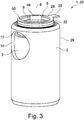
3 zeigt eine Gesamtansicht des Ventils20 mit Blick auf eine erste Öffnung8 , eine zweite Öffnung10 und einen Ring50 bzw.ein Verdrehsicherungselement 24 sowie eine Abflachung48 . -
4 zeigt eine Draufsicht auf das in3 dargestellte Ventil 20 in einer um dieVentilachse 6 gedrehten Ansicht desVentils 20 . -
5 zeigt ein Detail des Ventils20 in einer Schnittdarstellung, entlang eines nach4 in der Ebene V-V verlaufenden Querschnitts durchdas Ventil 20 . -
6 zeigt einen Querschnitt des Ventils20 in der in5 mit VI-VI markierten Querschnittsebene. -
7 zeigt das in1 markierte Detail Y des Ventils20 ohne den Ring 50 in einer nicht maßstäblichen und vergrößerten Darstellung. -
8 zeigt in einer weiteren Schnittdarstellung das in1 mit Y markierte Detail des Ventils20 als ein Zwischenstadiums 30 eines Verfahrens, bei dem derRing 50 formschlüssig amRand 16 der ersten Öffnung8 verankert wird. -
9 zeigt eine Vorrichtung37 zur Regelung von Drücken eines Strömungsmittels in einem Fahrzeuggetriebe in einem Längsschnitt entlang der Ventilachse6 . -
10 zeigt die in9 dargestellte Vorrichtung 37 in einer quer zur Ventilachse6 gerichteten Schnittdarstellung.
-
1 shows a as apressure compensation valve 1 executedvalve 20 in a longitudinal section along thevalve axis 6 . -
2nd shows that in1 marked detail Z of thevalve 20 in an enlarged scale, not to scale. -
3rd shows an overall view of thevalve 20 facing a first opening8th , a second opening10th and aring 50 or an anti-rotation element24th as well as a flattening48 . -
4th shows a top view of the in3rd valve shown20 in one around thevalve axis 6 rotated view of thevalve 20 . -
5 shows a detail of thevalve 20 in a sectional view, along a4th cross-section through the valve in theplane VV 20 . -
6 shows a cross section of thevalve 20 in the in5 cross-sectional plane marked with VI-VI. -
7 shows that in1 marked detail Y of thevalve 20 without thering 50 not to scale and enlarged. -
8th shows the in a furthersectional view 1 Detail of the valve marked withY 20 as an intermediate stage30th a process in which thering 50 form-fitting on theedge 16 the first opening8th is anchored. -
9 shows adevice 37 for regulating pressures of a fluid in a vehicle transmission in a longitudinal section along thevalve axis 6 . -
10th shows the in9 showndevice 37 in a cross to thevalve axis 6 directional sectional view.
An der Rückseite des Druckausgleichventils
Das hülsenförmig ausgebildete Ventilgehäuse
Der in der Gesamtansicht nach
Als Zwischenstadium ist in diesem Fall ein Schritt zu verstehen, bei dem der Ring
In dem dargestellten Fall ist der Ventilsitz alternativ zu der Darstellung nach
In this case, the intermediate stage is a step in which the
In the case shown, the valve seat is an alternative to that shown in FIG
Die Vorrichtung
Es wird davon ausgegangen, dass das in
Wenn der Druck im ersten Kanal
BezugszeichenlisteReference list
- 11
- DruckausgleichsventilPressure compensation valve
- 22nd
- VentilgehäuseValve body
- 33rd
- Kolbenpiston
- 4 4th
- StützelementSupport element
- 55
- Federfeather
- 66
- VentilachseValve axis
- 77
- KolbenbodenPiston crown
- 88th
- erste Öffnungfirst opening
- 99
- KolbenmantelPiston skirt
- 1010th
- zweite Öffnungsecond opening
- 1111
- ÜbergangsabschnittTransition section
- 1212th
- spaltförmige Durchgangsöffnungslit-shaped through opening
- 1313
- RingkanalRing channel
- 1414
- kalottenförmige Flächedome-shaped surface
- 1515
- konvexe Ringflächeconvex ring surface
- 1616
- Randedge
- 1717th
- VentilsitzValve seat
- 1818th
- Fläche des KolbenbodensArea of the piston crown
- 1919th
- Grundkörper des RingesBasic body of the ring
- 2020
- VentilValve
- 2121
- UmfangsnutCircumferential groove
- 2222
- erster Kragenfirst collar
- 2323
- InnenkonturInner contour
- 23A23A
- zylindrischer Abschnitt der Innenkonturcylindrical section of the inner contour
- 23B23B
- tangentialer Abschnitt der Innenkonturtangential section of the inner contour
- 2424th
- VerdrehsicherungselementAnti-rotation element
- 2525th
- Vorsprunghead Start
- 2626
- Ausnehmung in dem GetriebebauteilRecess in the gear component
- 2828
- Vorsprung des StützelementsProjection of the support element
- 2929
- Außenkontur des VentilgehäusesOuter contour of the valve housing
- 3030th
- ZwischenstadiumIntermediate stage
- 3131
- Grundkörper des StützelementsBasic body of the support element
- 3232
- Ende des VentilsEnd of valve
- 3333
- offener Querschnitt des Ventilsopen cross section of the valve
- 3434
- Vorrichtung zur SicherungSecurity device
- 3535
- DurchgangsbohrungThrough hole
- 3636
- zweiter Kragensecond collar
- 3737
- Vorrichtungcontraption
- 3838
- Kegelmantelfläche des VentilsitzesTapered surface of the valve seat
- 3939
- hohlzylindrischer Abschnitthollow cylindrical section
- 4040
- HinterschnittUndercut
- 4141
- erster Kanalfirst channel
- 4242
- zweiter Kanalsecond channel
- 4444
- GetriebebauteilGear component
- 4545
- dritter Kanalthird channel
- 4646
- Rippe des VentilgehäusesRib of the valve body
- 4747
- UmformwerkzeugForming tool
- 4848
- AbflachungFlattening
- 4949
- FormschlußPositive locking
- 5050
- Ringring
- 5151
- Außenkontur des RingesOuter contour of the ring
- 51A51A
- zylindrischer Abschnitt der Außenkonturcylindrical section of the outer contour
- 51B51B
- tangentialer Abschnitt der Außenkonturtangential section of the outer contour
ZITATE ENTHALTEN IN DER BESCHREIBUNG QUOTES INCLUDE IN THE DESCRIPTION
Diese Liste der vom Anmelder aufgeführten Dokumente wurde automatisiert erzeugt und ist ausschließlich zur besseren Information des Lesers aufgenommen. Die Liste ist nicht Bestandteil der deutschen Patent- bzw. Gebrauchsmusteranmeldung. Das DPMA übernimmt keinerlei Haftung für etwaige Fehler oder Auslassungen.This list of documents listed by the applicant has been generated automatically and is only included for the better information of the reader. The list is not part of the German patent or utility model application. The DPMA assumes no liability for any errors or omissions.
Zitierte PatentliteraturPatent literature cited
- DE 102007002445 A1 [0003]DE 102007002445 A1 [0003]
- US 2590244 A [0003]US 2590244 A [0003]
- DE 19739904 A1 [0003]DE 19739904 A1 [0003]
- DE 102015211599 A1 [0003]DE 102015211599 A1 [0003]
Claims (10)
Priority Applications (1)
| Application Number | Priority Date | Filing Date | Title |
|---|---|---|---|
| DE102019120226.4A DE102019120226A1 (en) | 2019-07-26 | 2019-07-26 | Valve and device for regulating pressures of a fluid with the valve and device for securing the valve in the transmission component |
Applications Claiming Priority (1)
| Application Number | Priority Date | Filing Date | Title |
|---|---|---|---|
| DE102019120226.4A DE102019120226A1 (en) | 2019-07-26 | 2019-07-26 | Valve and device for regulating pressures of a fluid with the valve and device for securing the valve in the transmission component |
Publications (1)
| Publication Number | Publication Date |
|---|---|
| DE102019120226A1 true DE102019120226A1 (en) | 2020-08-06 |
Family
ID=71615588
Family Applications (1)
| Application Number | Title | Priority Date | Filing Date |
|---|---|---|---|
| DE102019120226.4A Ceased DE102019120226A1 (en) | 2019-07-26 | 2019-07-26 | Valve and device for regulating pressures of a fluid with the valve and device for securing the valve in the transmission component |
Country Status (1)
| Country | Link |
|---|---|
| DE (1) | DE102019120226A1 (en) |
Cited By (2)
| Publication number | Priority date | Publication date | Assignee | Title |
|---|---|---|---|---|
| US20220260165A1 (en) * | 2019-07-26 | 2022-08-18 | Schaeffler Technologies AG & Co. KG | Valve, device for regulating the pressure of a flow medium using the valve, and device for securing the valve in a transmission component |
| DE102023125766A1 (en) | 2023-09-22 | 2025-03-27 | Fft Produktionssysteme Gmbh & Co. Kg | Cartridge valve for a fluid system filling device, fluid system filling device with at least one such cartridge valve and method for filling a fluid system in vacuum-pressure filling |
Citations (5)
| Publication number | Priority date | Publication date | Assignee | Title |
|---|---|---|---|---|
| US2590244A (en) | 1948-02-21 | 1952-03-25 | Dixon T Harbison | Valve cage |
| DE19739904A1 (en) | 1997-09-11 | 1999-03-18 | Bosch Gmbh Robert | Check valve, especially for a piston pump |
| DE102007002445A1 (en) | 2007-01-17 | 2008-07-24 | Robert Bosch Gmbh | Check valve and injector with hydraulic interrupter and check valve |
| DE102015211599A1 (en) | 2015-06-23 | 2016-12-29 | Zf Friedrichshafen Ag | Valve |
| DE102018131097A1 (en) * | 2018-12-06 | 2020-05-14 | Schaeffler Technologies AG & Co. KG | Device for securing a pressure compensation valve in a transmission component, pressure compensation valve and device for regulating pressures of a fluid in a vehicle transmission |
-
2019
- 2019-07-26 DE DE102019120226.4A patent/DE102019120226A1/en not_active Ceased
Patent Citations (5)
| Publication number | Priority date | Publication date | Assignee | Title |
|---|---|---|---|---|
| US2590244A (en) | 1948-02-21 | 1952-03-25 | Dixon T Harbison | Valve cage |
| DE19739904A1 (en) | 1997-09-11 | 1999-03-18 | Bosch Gmbh Robert | Check valve, especially for a piston pump |
| DE102007002445A1 (en) | 2007-01-17 | 2008-07-24 | Robert Bosch Gmbh | Check valve and injector with hydraulic interrupter and check valve |
| DE102015211599A1 (en) | 2015-06-23 | 2016-12-29 | Zf Friedrichshafen Ag | Valve |
| DE102018131097A1 (en) * | 2018-12-06 | 2020-05-14 | Schaeffler Technologies AG & Co. KG | Device for securing a pressure compensation valve in a transmission component, pressure compensation valve and device for regulating pressures of a fluid in a vehicle transmission |
Cited By (3)
| Publication number | Priority date | Publication date | Assignee | Title |
|---|---|---|---|---|
| US20220260165A1 (en) * | 2019-07-26 | 2022-08-18 | Schaeffler Technologies AG & Co. KG | Valve, device for regulating the pressure of a flow medium using the valve, and device for securing the valve in a transmission component |
| US11808367B2 (en) * | 2019-07-26 | 2023-11-07 | Schaeffler Technologies AG & Co. KG | Valve, device for regulating the pressure of a flow medium using the valve, and device for securing the valve in a transmission component |
| DE102023125766A1 (en) | 2023-09-22 | 2025-03-27 | Fft Produktionssysteme Gmbh & Co. Kg | Cartridge valve for a fluid system filling device, fluid system filling device with at least one such cartridge valve and method for filling a fluid system in vacuum-pressure filling |
Similar Documents
| Publication | Publication Date | Title |
|---|---|---|
| EP1700058B1 (en) | Valve for controlling a fluid | |
| EP2356365B1 (en) | Closing device | |
| WO2021018341A1 (en) | Valve, device for regulating the pressure of a flow medium using the valve, and device for securing the valve in a transmission component | |
| DE112018003791T5 (en) | Shock absorber and method of manufacturing the same | |
| DE102018131097A1 (en) | Device for securing a pressure compensation valve in a transmission component, pressure compensation valve and device for regulating pressures of a fluid in a vehicle transmission | |
| DE102018131093A1 (en) | Valve and method for producing a valve and device for regulating pressures of a fluid in a vehicle transmission with a valve designed as a pressure compensation valve | |
| DE102019133669B4 (en) | Device with a component and a valve with a valve housing of the valve | |
| DE10324307B3 (en) | Quick-coupling unit with built-in no-return valve for air conditioning unit has bypass branch forming valve housing for no-return valve | |
| DE4215892C2 (en) | Pressure control valve and method of manufacturing the same | |
| DE102019120226A1 (en) | Valve and device for regulating pressures of a fluid with the valve and device for securing the valve in the transmission component | |
| DE102019120224A1 (en) | Valve and device for regulating pressures of a fluid with the valve and device for securing the valve in the transmission component | |
| EP1331978B1 (en) | Liquid filter comprising a valve arranged in the supporting tube of a filter element | |
| DE102013002452B4 (en) | Fluid technical device | |
| EP0082292A1 (en) | Closure cap, especially for a motor vehicle radiator | |
| EP3768562B1 (en) | Relay valve for a compressed air system | |
| DE102014213751A1 (en) | valve assembly | |
| EP3710733B1 (en) | Check valve element for a check valve assembly and corresponding check valve assembly | |
| DE102019132416B4 (en) | Valve and device for controlling pressures of a fluid with the valve and device for securing the valve in the transmission component | |
| DE102019133667B4 (en) | Device for regulating pressures of a fluid with a valve | |
| DE102019120227A1 (en) | Valve and device for regulating pressures of a fluid with the valve and device for securing the valve in the transmission component | |
| DE3326811A1 (en) | Stem or shaft seal, in particular a valve-stem seal | |
| DE10044897A1 (en) | Caulking stamp and caulking | |
| WO2024068694A1 (en) | Piston rod guide having a throttle valve, interchangeable valve pin set and method for setting damping force | |
| DE102018131094A1 (en) | Valve | |
| DE102018220673A1 (en) | Solenoid valve, in particular for slip-controlled motor vehicle brake systems |
Legal Events
| Date | Code | Title | Description |
|---|---|---|---|
| R012 | Request for examination validly filed | ||
| R230 | Request for early publication | ||
| R002 | Refusal decision in examination/registration proceedings | ||
| R003 | Refusal decision now final |