DE102018131093A1 - Valve and method for producing a valve and device for regulating pressures of a fluid in a vehicle transmission with a valve designed as a pressure compensation valve - Google Patents
Valve and method for producing a valve and device for regulating pressures of a fluid in a vehicle transmission with a valve designed as a pressure compensation valve Download PDFInfo
- Publication number
- DE102018131093A1 DE102018131093A1 DE102018131093.5A DE102018131093A DE102018131093A1 DE 102018131093 A1 DE102018131093 A1 DE 102018131093A1 DE 102018131093 A DE102018131093 A DE 102018131093A DE 102018131093 A1 DE102018131093 A1 DE 102018131093A1
- Authority
- DE
- Germany
- Prior art keywords
- valve
- piston
- valve housing
- opening
- spring
- Prior art date
- Legal status (The legal status is an assumption and is not a legal conclusion. Google has not performed a legal analysis and makes no representation as to the accuracy of the status listed.)
- Ceased
Links
- 239000012530 fluid Substances 0.000 title claims abstract description 27
- 230000005540 biological transmission Effects 0.000 title claims abstract description 22
- 238000004519 manufacturing process Methods 0.000 title claims abstract description 17
- 230000001105 regulatory effect Effects 0.000 title claims abstract description 8
- 230000007704 transition Effects 0.000 claims description 14
- 239000002184 metal Substances 0.000 claims description 13
- 238000004080 punching Methods 0.000 claims description 5
- 238000000034 method Methods 0.000 claims description 4
- 238000003825 pressing Methods 0.000 claims description 3
- 210000003746 feather Anatomy 0.000 description 4
- 238000005520 cutting process Methods 0.000 description 3
- 230000000694 effects Effects 0.000 description 3
- 238000003754 machining Methods 0.000 description 3
- 238000005096 rolling process Methods 0.000 description 3
- 239000012208 gear oil Substances 0.000 description 2
- 230000002093 peripheral effect Effects 0.000 description 2
- 239000007787 solid Substances 0.000 description 2
- 238000009966 trimming Methods 0.000 description 2
- BUHVIAUBTBOHAG-FOYDDCNASA-N (2r,3r,4s,5r)-2-[6-[[2-(3,5-dimethoxyphenyl)-2-(2-methylphenyl)ethyl]amino]purin-9-yl]-5-(hydroxymethyl)oxolane-3,4-diol Chemical compound COC1=CC(OC)=CC(C(CNC=2C=3N=CN(C=3N=CN=2)[C@H]2[C@@H]([C@H](O)[C@@H](CO)O2)O)C=2C(=CC=CC=2)C)=C1 BUHVIAUBTBOHAG-FOYDDCNASA-N 0.000 description 1
- 241001295925 Gegenes Species 0.000 description 1
- 230000002411 adverse Effects 0.000 description 1
- 238000000576 coating method Methods 0.000 description 1
- 230000006835 compression Effects 0.000 description 1
- 238000007906 compression Methods 0.000 description 1
- 239000000463 material Substances 0.000 description 1
- 239000003921 oil Substances 0.000 description 1
- 238000007789 sealing Methods 0.000 description 1
Images


Classifications
-
- F—MECHANICAL ENGINEERING; LIGHTING; HEATING; WEAPONS; BLASTING
- F16—ENGINEERING ELEMENTS AND UNITS; GENERAL MEASURES FOR PRODUCING AND MAINTAINING EFFECTIVE FUNCTIONING OF MACHINES OR INSTALLATIONS; THERMAL INSULATION IN GENERAL
- F16K—VALVES; TAPS; COCKS; ACTUATING-FLOATS; DEVICES FOR VENTING OR AERATING
- F16K17/00—Safety valves; Equalising valves, e.g. pressure relief valves
- F16K17/02—Safety valves; Equalising valves, e.g. pressure relief valves opening on surplus pressure on one side; closing on insufficient pressure on one side
- F16K17/04—Safety valves; Equalising valves, e.g. pressure relief valves opening on surplus pressure on one side; closing on insufficient pressure on one side spring-loaded
- F16K17/0466—Safety valves; Equalising valves, e.g. pressure relief valves opening on surplus pressure on one side; closing on insufficient pressure on one side spring-loaded with a special seating surface
-
- F—MECHANICAL ENGINEERING; LIGHTING; HEATING; WEAPONS; BLASTING
- F16—ENGINEERING ELEMENTS AND UNITS; GENERAL MEASURES FOR PRODUCING AND MAINTAINING EFFECTIVE FUNCTIONING OF MACHINES OR INSTALLATIONS; THERMAL INSULATION IN GENERAL
- F16H—GEARING
- F16H57/00—General details of gearing
- F16H57/04—Features relating to lubrication or cooling or heating
- F16H57/0434—Features relating to lubrication or cooling or heating relating to lubrication supply, e.g. pumps; Pressure control
- F16H57/0435—Pressure control for supplying lubricant; Circuits or valves therefor
-
- F—MECHANICAL ENGINEERING; LIGHTING; HEATING; WEAPONS; BLASTING
- F16—ENGINEERING ELEMENTS AND UNITS; GENERAL MEASURES FOR PRODUCING AND MAINTAINING EFFECTIVE FUNCTIONING OF MACHINES OR INSTALLATIONS; THERMAL INSULATION IN GENERAL
- F16K—VALVES; TAPS; COCKS; ACTUATING-FLOATS; DEVICES FOR VENTING OR AERATING
- F16K27/00—Construction of housing; Use of materials therefor
- F16K27/02—Construction of housing; Use of materials therefor of lift valves
- F16K27/0209—Check valves or pivoted valves
Landscapes
- Engineering & Computer Science (AREA)
- General Engineering & Computer Science (AREA)
- Mechanical Engineering (AREA)
- Safety Valves (AREA)
Abstract
Die Erfindung betrifft ein Ventil (1) mit einem Ventilgehäuse (2), wenigstens einem Kolben (3), mindestens einem Stützelement (4) und zumindest einer Feder (5), mit den Merkmalen:- der Kolben (3) und das Ventilgehäuse (2) sind zueinander koaxial auf einer gedachten Ventilachse (6) angeordnet, wobei die Ventilachse (6) in eine erste axiale Richtung sowie in eine zur ersten axialen Richtung entgegengesetzte zweite axiale Richtung ausgerichtet ist,- der Kolben (3) ist gegen Federkräfte der Feder (5) axial beweglich in dem Ventilgehäuse (2) aufgenommen, wobei die Feder (5) zumindest in die erste axiale Richtung an dem Stützelement (4) und in die zweite axiale Richtung an dem Kolben (3) abgestützt ist,- das Ventilgehäuse (2) ist mit einer für Strömungsmittel durchlässigen und durch einen Kolbenboden (7) des Kolbens (3) verschließbaren ersten Öffnung (8) versehen,- das Ventilgehäuse (2) ist mit einer durch einen Kolbenmantel (9) des Kolbens (3) zumindest teilweise verschließbaren und für die Strömungsmittel durchlässigen zweiten Öffnung (10) versehen,- der Kolbenmantel (9) erstreckt sich von dem Kolbenboden (7) aus axial in Richtung des Stützelements (4) und umgibt dabei die Ventilachse (6). Die Erfindung betrifft weiterhin ein Verfahren zur Herstellung des Ventils (20) und eine Vorrichtung (37) zur Regelung von Drücken eines Strömungsmittels in einem Fahrzeuggetriebe mit einem als Druckausgleichsventil (1) ausgebildeten Ventil (20).The invention relates to a valve (1) with a valve housing (2), at least one piston (3), at least one support element (4) and at least one spring (5), with the features: - the piston (3) and the valve housing ( 2) are arranged coaxially to one another on an imaginary valve axis (6), the valve axis (6) being oriented in a first axial direction and in a second axial direction opposite to the first axial direction, - the piston (3) is against spring forces of the spring (5) axially movably received in the valve housing (2), the spring (5) being supported at least in the first axial direction on the support element (4) and in the second axial direction on the piston (3), - the valve housing ( 2) is provided with a first opening (8) which is permeable to fluid and which can be closed by a piston crown (7) of the piston (3), - the valve housing (2) is at least partially covered by a piston jacket (9) of the piston (3) lockable and for the Provided fluid-permeable second opening (10), - the piston skirt (9) extends axially from the piston head (7) in the direction of the support element (4) and thereby surrounds the valve axis (6). The invention further relates to a method for producing the valve (20) and a device (37) for regulating pressures of a fluid in a vehicle transmission with a valve (20) designed as a pressure compensation valve (1).
Description
Gebiet der ErfindungField of the Invention
Die Erfindung betrifft ein Ventil mit einem Ventilgehäuse, wenigstens einem Kolben, mindestens einem Stützelement und zumindest einer Feder, mit den Merkmalen:
- - der Kolben und das Ventilgehäuse sind zueinander koaxial auf einer gedachten Ventilachse angeordnet, wobei die Ventilachse in eine erste axiale Richtung sowie in eine zur ersten axialen Richtung entgegengesetzte zweite axiale Richtung ausgerichtet ist,
- - der Kolben ist gegen Federkräfte der Feder axial beweglich in dem Ventilgehäuse aufgenommen, wobei die Feder zumindest in die erste axiale Richtung an dem Stützelement und in die zweite axiale Richtung an dem Kolben abgestützt ist,
- - das Ventilgehäuse ist mit einer für Strömungsmittel durchlässigen und durch einen Kolbenboden des Kolbens verschließbaren ersten Öffnung versehen,
- - das Ventilgehäuse ist mit einer durch einen Kolbenmantel des Kolbens zumindest teilweise verschließbaren und für die Strömungsmittel durchlässigen zweiten Öffnung versehen,
- - der Kolbenmantel erstreckt sich von dem Kolbenboden aus axial in Richtung des Stützelements und umgibt dabei die Ventilachse,
- - die erste Öffnung und der Kolbenboden sind koaxial der Ventilachse angeordnet. Die Erfindung betrifft weiterhin ein Verfahren zur Herstellung eines derartigen Ventil, eine Vorrichtung zur Regelung von Drücken eines Strömungsmittels in einem Fahrzeuggetriebe mit einem als Druckausgleichsventil ausgeführten Ventil sowie eine Vorrichtung zur Sicherung des Druckausgleichsventils in einem Getriebebauteil.
- the piston and the valve housing are arranged coaxially to one another on an imaginary valve axis, the valve axis being oriented in a first axial direction and in a second axial direction opposite to the first axial direction,
- the piston is axially movably received in the valve housing against spring forces of the spring, the spring being supported at least in the first axial direction on the support element and in the second axial direction on the piston,
- the valve housing is provided with a first opening which is permeable to fluid and can be closed by a piston crown of the piston,
- the valve housing is provided with a second opening which is at least partially closable by a piston jacket of the piston and permeable to the fluids,
- the piston skirt extends axially from the piston head in the direction of the support element and thereby surrounds the valve axis,
- - The first opening and the piston crown are arranged coaxially with the valve axis. The invention further relates to a method for producing such a valve, a device for regulating pressures of a fluid in a vehicle transmission with a valve designed as a pressure compensation valve, and a device for securing the pressure compensation valve in a transmission component.
Hintergrund der ErfindungBackground of the Invention
Druckausgleichsventile werden in Ölkanälen von Getriebe verbaut. Steigt der Druck des Getriebeöles im Kanal auf bzw. über einen definierten Druck an, gibt ein Kolben des Ventils eine Einlassöffnung frei. Das Getriebeöl strömt durch das Ventil über eine Auslassöffnung in einen Bypass- oder Rückflusskanal, bis der Druck das definierte Niveau unterschreitet und die Einlassöffnung durch den Kolben wieder verschlossen wird.Pressure compensation valves are installed in the oil channels of gearboxes. If the pressure of the gear oil in the duct rises to or above a defined pressure, a piston of the valve opens an inlet opening. The gear oil flows through the valve through an outlet opening into a bypass or return flow channel until the pressure falls below the defined level and the inlet opening is closed again by the piston.
Beschreibung der ErfindungDescription of the invention
Die Aufgabe der Erfindung ist es, die vorgenannten Nachteile zu beseitigen.The object of the invention is to eliminate the aforementioned disadvantages.
Die Aufgabe ist nach dem Gegenstand des Anspruchs 1 gelöst.The object is achieved according to the subject matter of claim 1.
Die zweite Öffnung ist quer zur ersten Öffnung ausgerichtet und in ein aus Blech hergestelltes Ventilgehäuse, vorzugsweise durch Stanzen, eingebracht. Die zweite Öffnung erstreckt sich mit radialem Abstand zur Ventilachse in axialer Richtung. Die Mittenachse der Öffnung verläuft in radialer Richtung senkrecht zur Ventilachse. Das Ventilgehäuse lässt sich einfach und kostengünstig herstellen.The second opening is aligned transversely to the first opening and is introduced into a valve housing made of sheet metal, preferably by stamping. The second opening extends in the axial direction at a radial distance from the valve axis. The central axis of the opening runs in the radial direction perpendicular to the valve axis. The valve housing is easy and inexpensive to manufacture.
Eine Ausgestaltung der Erfindung sieht vor, dass der Kolben über den Kolbenmantel axial beweglich in dem Ventilgehäuse sowie radial in dem Ventilgehäuse zentriert geführt ist. Dadurch ergibt sich vorteilhaft eine im wesentlichen druckdichte und zugleich axial bewegliche Führung des Kolbens im Ventilgehäuse, insbesondere dann, wenn das Radialspiel, mit dem der Kolben radial im Gehäuse zentriert ist, sehr gering ist. Das Spiel beträgt zum Beispiel 30 µm. Die Gleitflächen, d. h., die Durchmesser der innenzylindrischen Fläche des Ventilgehäuses und der außenzylindrischen Fläche des Kolbens können beim Ziehen dieser Bauelemente spanlos aus Blech ohne spanabhebende Nachbearbeitung sehr genau eingestellt werden. Gegebenenfalls sind Gleitbeschichtungen auf den Oberflächen der Bauelemente vorteilhaft.One embodiment of the invention provides that the piston is guided axially movably in the valve housing and radially centered in the valve housing via the piston jacket. This advantageously results in a substantially pressure-tight and at the same time axially movable guidance of the piston in the valve housing, in particular when the radial play with which the piston is centered radially in the housing is very small. For example, the game is 30 µm. The sliding surfaces, i.e. that is, the diameters of the inner cylindrical surface of the valve housing and the outer cylindrical surface of the piston can be set very precisely when drawing these components without cutting out of sheet metal without machining. If necessary, sliding coatings on the surfaces of the components are advantageous.
Der Kolben ist gegen die Federkräfte der Feder aus einer Schließstellung in eine Öffnungsstellung axial beweglich in dem Ventilgehäuse geführt. In der Schließstellung des Kolbens ist die erste Öffnung durch den Kolbenboden verschlossen und die zweite Öffnung zumindest teilweise durch den Kolbenmantel. In der Öffnungsstellung hat der Kolbenboden vom Ventilsitz abgehoben. Wenigstens eine Kante oder eine Kontur des Kolbens gibt dabei analog einer Steuerkante die zweite Öffnung frei, so dass eine für Strömungsmittel durchgängige Verbindung zwischen der ersten Öffnung und der zweiten Öffnung ausgebildet ist. Dabei ist das der ersten Öffnung axial gegenüberliegende offene Ende des Ventilgehäuses sowohl in der Schließstellung als auch in der Öffnungsstellung durch den Kolben, vorbehaltlich eines durch Radialspiel bedingten Leckspalts durch den Kolben, gegenüber dem Strömungsmittel abgedichtet.The piston is guided against the spring forces of the spring from a closed position into an open position axially movable in the valve housing. In the closed position of the piston, the first opening is closed by the piston head and the second opening is at least partially closed by the piston jacket. In the open position, the piston crown has lifted off the valve seat. At least one edge or a contour of the piston exposes the second opening analogously to a control edge, so that a connection between the first opening and the second which is continuous for fluid is provided Opening is formed. The open end of the valve housing axially opposite the first opening is sealed from the fluid both in the closed position and in the open position by the piston, subject to a leakage gap caused by the piston due to radial play.
Eine weitere Ausgestaltung der Erfindung sieht in diesem Zusammenhang vor, dass schon bzw. noch in der Schließstellung die zweite Öffnung, die in diesem Fall eine Rückführöffnung ist, durch den Kolbenmantel nur teilweise verschlossen ist. Daraus ergibt sich, dass eine spaltförmige für die Strömungsmittel durchlässige Durchgangsöffnung der zweiten Öffnung in der Schließstellung nicht von dem Kolbenmantel verdeckt und nicht von dem Kolben verschlossen ist. Die spaltförmige Durchgangsöffnung ist zumindest in der Schließstellung durch einen Anteil des Kolbens und einen Rand der zweiten Öffnung begrenzt. Der Vorteil der Erfindung liegt darin, dass sofort nach Öffnen des Ventils ein für das Strömungsmittel durchlässiger Durchgang zwischen der ersten Öffnung und der zweiten Öffnung ausgebildet ist und der Druck schnell reduziert wird. Das wirkt sich vorteilhaft bei der Auslegung der Feder aus.In this context, a further embodiment of the invention provides that the second opening, which in this case is a return opening, is only partially closed by the piston jacket already or still in the closed position. It follows from this that a gap-shaped through-opening of the second opening, which is permeable to the fluids, is not covered by the piston skirt in the closed position and is not closed by the piston. The gap-shaped through opening is limited at least in the closed position by a portion of the piston and an edge of the second opening. The advantage of the invention is that immediately after opening the valve, a passage permeable to the fluid is formed between the first opening and the second opening and the pressure is quickly reduced. This has an advantageous effect when designing the spring.
Die gleiche Wirkung wird erzielt, wenn zwischen dem Kolben und dem Ventilgehäuse ein Ringkanal ausgebildet ist, welcher sich unmittelbar an den Ventilsitz anschließt. Der Ringkanal kann durch die Gestaltung des Ventilgehäuses und des Kolbens beliebig ausgelegt werden. Der Ringkanal füllt sich unmittelbar nach dem Abheben des Kolbens vom Ventilsitz mit dem Strömungsmittel. Der Druck des Strömungsmittels wird dadurch an einer größeren Fläche des Kolbens umgesetzt.The same effect is achieved if an annular channel is formed between the piston and the valve housing, which connects directly to the valve seat. The ring channel can be designed as desired through the design of the valve housing and the piston. The annular channel fills with the fluid immediately after the piston is lifted off the valve seat. The pressure of the fluid is thereby converted on a larger area of the piston.
Die gleiche Wirkung wird auch erzielt, wenn, wie eine Ausgestaltung der Erfindung vorsieht, der Kolbenboden und der Kolbenmantel mittels eines an dem Kolben ausgebildeten Übergangsabschnitts miteinander verbunden sind. Dabei ist durch den Übergangsabschnitt und durch einen dem Übergangsabschnitt gegenüberliegenden Abschnitt des Ventilgehäuses zumindest in der Schließstellung ein Ringkanal begrenzt.The same effect is also achieved if, as an embodiment of the invention provides, the piston crown and the piston skirt are connected to one another by means of a transition section formed on the piston. An annular channel is delimited by the transition section and by a section of the valve housing opposite the transition section, at least in the closed position.
Mit einer Ausgestaltung der Erfindung ist eine Kombination beider Maßnahmen vorgesehen. Dabei ist der Ringkanal bereits in der Schließstellung des Kolbens an der spaltförmigen Durchgangsöffnung zur zweiten Öffnung hin geöffnet.A combination of both measures is provided with an embodiment of the invention. The annular channel is already open in the closed position of the piston at the slot-shaped through opening toward the second opening.
Aus den vorhergehend genannten Maßnahmen ergibt sich, dass der Druck, der zum Öffnen des Ventils notwendig ist, größer ist als der Druck, der in dem Ventil vorherrscht, wenn der Kolben vom Ventilsitz abgehoben hat. Der Vorteil einer derartigen Anordnung liegt darin, dass Werte für die Öffnungs-und Schließdrücke des erfindungsgemäßen Ventils konstant und prozeßsicher eingestellt werden können und der Druckausgleich innerhalb kürzester Zeit stattfindet.It follows from the measures mentioned above that the pressure which is necessary to open the valve is greater than the pressure which prevails in the valve when the piston has lifted off the valve seat. The advantage of such an arrangement is that values for the opening and closing pressures of the valve according to the invention can be set constantly and reliably and the pressure equalization takes place within a very short time.
Mit einer weiteren Ausgestaltung der Erfindung ist vorgesehen, dass das Ventil mit einem hülsenförmig ausgebildeten Ventilgehäuse versehen ist, welches durch einen zur Ventilachse konzentrisch ausgerichteten Hülsenmantel und einen radial in Richtung der Ventilachse ausgerichteten sowie um die erste Öffnung verlaufenden Rand aus dem Blech aufweist. Der Rand ist wahlweise mit einem separaten und an dem Rand befestigten Ventilsitz versehen oder der Ventilsitz ist direkt in den Rand aus Blech geprägt. Eine derartige Lösung lässt sich sehr kostengünstig herstellen. Eine kostenaufwendige spanabhebende Bearbeitung eines Ventilsitzes entfällt.A further embodiment of the invention provides that the valve is provided with a sleeve-shaped valve housing, which has a sleeve jacket which is concentrically aligned with the valve axis and a rim made of sheet metal which is aligned radially in the direction of the valve axis and extends around the first opening. The edge is optionally provided with a separate valve seat attached to the edge or the valve seat is stamped directly into the edge from sheet metal. Such a solution can be produced very inexpensively. There is no costly machining of a valve seat.
Eine Ausgestaltung der Erfindung sieht vor, dass der Kolben hülsenförmig mit einem hohlzylindrischen Kolbenmantel und einem den Kolben an einer Seite verschließenden Kolbenboden gebildet ist, wobei die Feder axial von dem Kolbenmantel umgeben und axial innen im Kolben an dem Kolbenboden abgestützt ist. Der Kolben ist vorzugsweise aus Blech gefertigt. Der Kolbenboden ist entsprechend dünnwandig. Gegenüber massiv ausgebildeten Kolben steht somit mehr axialer Bauraum für die Feder zur Verfügung, da das Innere des Kolbens auch als Bauraum für die Feder zur Verfügung steht. Dadurch stehen bei der Auswahl und Auslegung der Feder, die auch aus mehreren parallel oder in Reihe geschalteten Federn bestehen kann, mehr Möglichkeiten zur Verfügung.An embodiment of the invention provides that the piston is formed in the form of a sleeve with a hollow cylindrical piston jacket and a piston head closing the piston on one side, the spring being axially surrounded by the piston jacket and axially supported in the piston on the piston head. The piston is preferably made of sheet metal. The piston crown is accordingly thin-walled. Compared to solid pistons, there is more axial space available for the spring, since the inside of the piston is also available as space for the spring. This means that more options are available when selecting and designing the spring, which can also consist of several springs connected in parallel or in series.
Schließlich ist mit einer Ausgestaltung der Erfindung vorgesehen, dass das Stützelement an einem von der ersten Öffnung abgewandten Ende des Ventilgehäuses in eine Umfangsnut eingesetzt und in der Umfangsnut zumindest axial abgestützt ist. Durch die formschlüssige Sicherung des Stützelements an dem Ventilgehäuse werden Verformungen, die durch einen Presssitz zwischen dem Ventilgehäuse und dem Stützelement hervorgerufen werden können, von vornherein vermieden. Die Genauigkeit des Ventilsitzes ist damit jedem Fall gegeben. Die für den Formschluß notwendige Umfangsnut in dem Ventilgehäuse lässt sich einfach in den Umformungsprozess bei der Herstellung des Ventilgehäuses aus Blech ohne zusätzlichen spanabhebenden Aufwand einbringen.Finally, one embodiment of the invention provides that the support element is inserted into a circumferential groove at an end of the valve housing facing away from the first opening and is at least axially supported in the circumferential groove. The form-fitting securing of the support element to the valve housing prevents deformations which can be caused by a press fit between the valve housing and the support element from the outset. The accuracy of the valve seat is given in any case. The circumferential groove in the valve housing which is necessary for the positive locking can easily be introduced into the forming process in the production of the valve housing from sheet metal without additional machining effort.
Die Erfindung sieht in dem zuvor genannten Zusammenhang eine Vorrichtung zur Regelung von Drücken eines Strömungsmittels in einem Fahrzeuggetriebe vor. Die Vorrichtung ist aus einem Abschnitt eines Getriebebauteils, aus zumindest einem ersten Kanal und einem zweiten Kanal sowie aus dem Ventil gebildet und weist eine Vorrichtung zur Sicherung des Ventils bzw. lageorientierten Montage in dem Getriebebauteil auf. Der erste Kanal führt in dem Abschnitt des Getriebebauteils zu der ersten Öffnung und die zweite Öffnung mündet in den zweiten Kanal. Der an dem Stützelement ausgebildete Vorsprung durchgreift radial das Ventilgehäuse, greift dabei formschlüssig in eine Ausnehmung des Ventilgehäuses ein, ragt über die Außenkontur des Ventilgehäuses radial hinaus und über die Innenkontur des Ventilsitzes im Getriebebauteil radial hinaus in eine Ausnehmung des Getriebebauteils hinein. Die Vorrichtung zur Sicherung eines Druckausgleichsventils im Getriebebauteil ist dabei lediglich durch den Vorsprung und die Ausnehmung gebildet und somit sehr einfach und kostengünstig herzustellen.In the aforementioned context, the invention provides a device for regulating pressures of a fluid in a vehicle transmission. The device is formed from a section of a transmission component, from at least a first channel and a second channel and from the valve and has a device for Securing the valve or position-oriented assembly in the gear component. The first channel leads to the first opening in the section of the transmission component and the second opening opens into the second channel. The protrusion formed on the support element penetrates radially through the valve housing, engages in a form-fitting manner in a recess in the valve housing, projects radially beyond the outer contour of the valve housing and radially beyond the inner contour of the valve seat in the gear component into a recess in the gear component. The device for securing a pressure compensation valve in the transmission component is merely formed by the projection and the recess and is therefore very simple and inexpensive to manufacture.
Durch die lageorientierte Montage ist zum Beispiel sichergestellt, dass die zweite Öffnung und der zweite Kanal exakt zueinander ausgerichtet werden. Das ist insbesondere dann von Vorteil, wenn, wie mit einer Ausgestaltung der Erfindung vorgesehen ist, die erste Öffnung und der Kolbenboden koaxial der Ventilachse angeordnet und dabei aber die zweite Öffnung in dem Ventilgehäuse quer zur ersten Öffnung ausgerichtet ist. Die durch den ersten Vorsprung und die Ausnehmung gebildete Formschlussverbindung zwischen dem Ventil und dem Getriebebauteil ist vorteilhaft an einer der zweiten Öffnung gegenüberliegenden Seite des Ventilgehäuses ausgebildet, welche zum Beispiel eine Längsnut in dem als Gehäuse oder Getriebewelle ausgebildeten Getriebebauteil ist.The position-oriented assembly ensures, for example, that the second opening and the second channel are exactly aligned with each other. This is particularly advantageous if, as is provided with an embodiment of the invention, the first opening and the piston crown are arranged coaxially with the valve axis and the second opening in the valve housing is oriented transversely to the first opening. The form-fitting connection formed by the first projection and the recess between the valve and the gear component is advantageously formed on a side of the valve housing opposite the second opening, which is, for example, a longitudinal groove in the gear component designed as a housing or gear shaft.
Die zweite Öffnung ist quer zur ersten Öffnung ausgerichtet und in ein aus Blech hergestelltes Ventilgehäuse, vorzugsweise durch Stanzen, eingebracht. Die zweite Öffnung erstreckt sich mit radialem Abstand zur Ventilachse in axialer Richtung. Die Mittenachse der Öffnung verläuft in radialer Richtung senkrecht zur Ventilachse. Das Ventilgehäuse lässt sich einfach und kostengünstig herstellen.The second opening is aligned transversely to the first opening and is introduced into a valve housing made of sheet metal, preferably by stamping. The second opening extends in the axial direction at a radial distance from the valve axis. The central axis of the opening runs in the radial direction perpendicular to the valve axis. The valve housing is easy and inexpensive to manufacture.
Weiterhin ist ein Verfahren zur Herstellung eines erfindungsgemäßen Ventils vorgesehen:
- - Das Ventilgehäuse wird aus Blech durch Kaltumformen und Stanzen hergestellt. Dabei wird ein hohlzylindrisches Bauteil geformt, welches an einem Ende offen ist. Das hohlzylindrische Bauteil ist im zylindrischen Bereich durch mindestens zwei Wandstärken beispielsweise an einer Ziehstufe charakterisiert. Dabei ist die Wandstärke am offenen Ende geringer als an dem darauf in Richtung des Ventilsitzes folgenden Wandabschnitt. Außerdem werden durch Stanzen die Ausnehmung für die Formschlussverbindung und die zweite Öffnung eingebracht und der Ventilsitz gestanzt und geprägt.
- - Der Wandabschnitt mit der geringeren Wandstärke an dem offenen Ende des Ventilgehäuses wird durch Rollieren oder Walzen radial in Richtung der Ventilachse so umgeformt, dass die Umfangsnut entsteht. Dabei ist die Umfangsnut axial in die eine Richtung durch den dickeren Wandabschnitt und am offenen Ende durch einen umgebogenen Abschnitt des dünneren Wandabschnitts begrenzt.
- - Nach der Herstellung des Ventilgehäuses und des Kolbens werden der Kolben und die Feder in das Ventilgehäuse eingeführt. Alternativ wird zuerst die Feder in den Kolben eingeführt, bis diese am Kolbenboden anliegt und dann wird der Kolben zusammen mit der Feder in das Ventilgehäuse eingesetzt.
- - Das Stützelement wird koaxial zum Ventilgehäuse so ausgerichtet, dass es der Öffnung für die Formschlussverbindung axial gegenüberliegt.
- - Das Stützelement wird in das Gehäuse eingesetzt. Dabei werden die Zacken des Stützelementes in die Umfangsnut des Ventilgehäuses eingeschnappt.
- - Einsetzen bzw. Einpressen des Ventilgehäuses in ein Getriebebauteil, beispielsweise in eine Getriebewelle oder in ein Getriebegehäuse.
- - The valve body is made from sheet metal by cold forming and stamping. A hollow cylindrical component is formed, which is open at one end. The hollow cylindrical component is characterized in the cylindrical region by at least two wall thicknesses, for example on a drawing step. The wall thickness at the open end is smaller than at the wall section following it in the direction of the valve seat. In addition, the recess for the positive connection and the second opening are made by punching and the valve seat is punched and embossed.
- - The wall section with the smaller wall thickness at the open end of the valve housing is shaped radially in the direction of the valve axis by rolling or rolling so that the circumferential groove is formed. The circumferential groove is limited axially in one direction by the thicker wall section and at the open end by a bent section of the thinner wall section.
- - After the manufacture of the valve housing and the piston, the piston and the spring are inserted into the valve housing. Alternatively, the spring is first inserted into the piston until it rests on the piston head and then the piston is inserted into the valve housing together with the spring.
- - The support element is aligned coaxially to the valve housing so that it is axially opposite the opening for the positive connection.
- - The support element is inserted into the housing. The prongs of the support element are snapped into the circumferential groove of the valve housing.
- - Inserting or pressing the valve housing into a gear component, for example into a gear shaft or into a gear housing.
FigurenlisteFigure list
Die Erfindung wird nachfolgend anhand eines Ausführungsbeispiels und weitere Ausgestaltungen der Erfindung eines Ventils beschrieben. Das Ventil ist in diesem Fall als ein Druckausgleichsventil ausgeführt und in einer Vorrichtung zur Regelung von Drücken eines Strömungsmittels bzw. einer Vorrichtung zur Sicherung des Ventils bzw. Druckausgleichsventils näher erläutert.
-
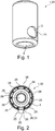
1 zeigt eine Gesamtansicht eines als Druckausgleichsventil1 ausgeführten Ventils20 . -
2 zeigt eine Rückansicht des Druckausgleichsventil1 nach1 . -
3 zeigt eine Schnittdarstellung des Druckausgleichsventils1 in einem Längsschnitt entlang der Ventilachse6 des Druckausgleichsventils1 , wobei derKolben 3 des Druckausgleichsventils1 sich in einer Schließstellung I befindet. -
4 zeigt eine Vorrichtung37 zur Regelung von Drücken eines Strömungsmittels in einem Fahrzeuggetriebe mit dem darin verbauten Druckausgleichsventil1 nach1 sowie einer Vorrichtung50 zur Sicherung des Druckausgleichsventils1 ineinem Getriebebauteil 44 .Die Vorrichtungen 37 und50 sowie das Druckausgleichsventil1 sind in einem Längsschnitt entlang der Ventilachse6 des Druckausgleichsventils1 dargestellt, wobei sich derKolben 3 des Druckausgleichsventils1 entsprechend der Darstellung nach4 in einer ÖffnungsstellungII indem Ventilgehäuse 2 befindet. -
5 zeigt ein Zwischenstadium eines erfindungsgemäßen Verfahrens, indem das Ventilgehäuse 2 als Einzelteil in einem Längsschnitt entlang der Ventilachse6 und eine ausdem Kolben 3 ,der Feder 5 und dem Stützelement 4 gebildete Vormontageeinheit für eine weitere Montage abgebildet sind. -
6 zeigt eine Gesamtansicht desStützelements 4 .
-
1 shows an overall view of a pressure equalization valve1 executed valve20th . -
2nd shows a rear view of the pressure compensation valve1 to1 . -
3rd shows a sectional view of the pressure compensation valve1 in a longitudinal section along thevalve axis 6 of the pressure compensation valve1 , the piston3rd of the pressure compensation valve1 is in a closed position I. -
4th shows adevice 37 for regulating pressures of a fluid in a vehicle transmission with the pressure compensation valve installed therein1 to1 and adevice 50 to secure the pressure compensation valve1 in agear component 44 . Thedevices 37 and50 as well as the pressure compensation valve1 are in a longitudinal section along thevalve axis 6 of Pressure compensation valve1 shown, with the piston3rd of the pressure compensation valve1 according to the illustration4th in an open positionII in the valve housing2nd located. -
5 shows an intermediate stage of a method according to the invention, in which the valve housing2nd as a single part in a longitudinal section along thevalve axis 6 and one from the flask3rd , thefeather 5 and the support member4th pre-assembly unit formed for further assembly are shown. -
6 shows an overall view of the support element4th .
Die Vorrichtung
Der Kolben
Anhand der
- - Herstellung des Ventilgehäuses
2 aus Blech durch Kaltumformen und Stanzen als ein hohlzylindrisches Bauteil, welches zumindest an einem Ende19 offen ist. Beim Kaltumformen wird einum eine Symmetrieachse 6 des Ventilgehäuses2 umlaufender Wandabschnitt27 an dem offenen Ende19 erzeugt. Diese radial gerichtete WandstärkeS1 ist kleiner, als die WandstärkeS2 eines auf den Wandabschnitt27 axial in Richtung der ersten Öffnung8 folgenden und zur Ventilachse6 hohlzylindrischen Hülsenmantels14 desVentilgehäuses 2 . Beim Stanzen wird eine Ausnehmung26 indas Ventilgehäuse 2 eingebracht, die maßgeblich Bestandteil der Formschlussverbindung ist. - -
Formen der Umfangsnut 21 , wobei der Wandabschnitt27 an dem offenen Ende19 durch Rollieren oder Bördeln so radial nach innen gebogen wird, dass eine zur Symmetrieachse hin offene Umfangsnut21 andem Ventilgehäuse 2 gebildet wird.Die Umfangsnut 21 ist in beliebigen gedachten und dabei entlang der Ventilachse6 geführten Längsschnitten durchdas Ventilgehäuse 2 axial in die eine Richtung durch Körperkanten des Hülsenmantels14 und in die andere axiale Richtung durch das in Richtung der Symmetrieachse gebogene freie Ende19 begrenzt. - -
Zentrieren der Feder 5 aufdem napfförmigen Grundkörper 62 desStützelements 4 , - - Einsetzen des Kolbens
3 indas Ventilgehäuse 2 ,Einbringen der Feder 5 und dabei Ausrichten des Stützelements4 zur Ventilachse 6 und dabei Ausrichten wenigstens desals Vorsprung 25 ausgebildeten Formschlußelements22 zu dem als die Ausnehmung26 ausgeführten zweiten Formschlußelement23 ; - - Einpressen des Stützelements
4 indas Ventilgehäuse 2 und dabei Befestigung des Stützelements4 durch Einschnappen indie Umfangsnut 21 .
- - Manufacture of the valve housing
2nd from sheet metal by cold forming and punching as a hollow cylindrical component, which at least at one end19th is open. In cold forming, one is around an axis ofsymmetry 6 of the valve housing2nd circumferential wall section27th at the open end19th generated. This radially directed wall thicknessS1 is smaller than the wall thicknessS2 one on the wall section27th axially towards the first opening8th following and to thevalve axis 6 hollowcylindrical sleeve jacket 14 of the valve housing2nd . When punching is arecess 26 in the valve housing2nd introduced, which is an integral part of the positive connection. - - Forming the circumferential groove
21st , the wall section27th at the open end19th by rolling or flanging it is bent radially inwards in such a way that a circumferential groove open towards the axis of symmetry21st on the valve housing2nd is formed. The circumferential groove21st is imagined in any and along thevalve axis 6 guided longitudinal sections through the valve housing2nd axially in one direction through body edges of thesleeve jacket 14 and in the other axial direction through the free end bent in the direction of the axis of symmetry19th limited. - - Center the
spring 5 on the bowl-shapedbody 62 of the support element4th , - - Insert the piston
3rd in the valve housing2nd , Insert thespring 5 and thereby aligning the support element4th to thevalve axis 6 and aligning at least that as a projection25th trainedpositive locking element 22 to that as therecess 26 executed second positive locking element23 ; - - Pressing in the support element
4th in the valve housing2nd and fastening the support element4th by snapping into the circumferential groove21st .
BezugszeichenlisteReference symbol list
- 11
- DruckausgleichsventilPressure compensation valve
- 22nd
- VentilgehäuseValve body
- 33rd
- Kolbenpiston
- 44th
- StützelementSupport element
- 55
- Federfeather
- 66
- VentilachseValve axis
- 77
- KolbenbodenPiston crown
- 88th
- erste Öffnungfirst opening
- 99
- KolbenmantelPiston skirt
- 1010th
- zweite Öffnungsecond opening
- 1111
- ÜbergangsabschnittTransition section
- 1212
- spaltförmige Durchgangsöffnungslit-shaped through opening
- 1313
- RingkanalRing channel
- 1414
- HülsenmantelSleeve jacket
- 15 15
- Abschnitt des VentilgehäusesSection of the valve housing
- 1616
- Randedge
- 1717th
- VentilsitzValve seat
- 1818th
- Durchlasspassage
- 1919th
- BereichArea
- 2020th
- VentilValve
- 2121st
- UmfangsnutCircumferential groove
- 2222
- erstes Formschlußelementfirst positive locking element
- 2323
- zweites Formschlußelementsecond positive locking element
- 2424th
- FormschlussverbindungPositive connection
- 2525th
- Vorsprunghead Start
- 2626
- AusnehmungRecess
- 2727th
- WandabschnittWall section
- 2828
- Vorsprung des StützelementsProjection of the support element
- 2929
- Außenkontur des Ventilgehäuses External contour of the valve housing
- 3737
- Vorrichtungcontraption
- 4141
- erster Kanalfirst channel
- 4242
- zweiter Kanalsecond channel
- 4343
- AusnehmungRecess
- 4444
- GetriebebauteilGear component
- 4848
- FormschlussverbindungPositive connection
- 4949
- Fasechamfer
- 5050
- Vorrichtungcontraption
- 5353
- MittenachseCenter axis
- 5555
- RingflächeRing surface
- 5656
- Flächearea
- 5757
- DurchgangsbohrungThrough hole
- 5959
- Fasechamfer
- 6060
- EndeThe End
- 6161
- VentilraumValve space
- 6262
- GrundkörperBasic body
- 6363
- FormschlussverbindungPositive connection
ZITATE ENTHALTEN IN DER BESCHREIBUNG QUOTES INCLUDE IN THE DESCRIPTION
Diese Liste der vom Anmelder aufgeführten Dokumente wurde automatisiert erzeugt und ist ausschließlich zur besseren Information des Lesers aufgenommen. Die Liste ist nicht Bestandteil der deutschen Patent- bzw. Gebrauchsmusteranmeldung. Das DPMA übernimmt keinerlei Haftung für etwaige Fehler oder Auslassungen.This list of documents listed by the applicant has been generated automatically and is only included for the better information of the reader. The list is not part of the German patent or utility model application. The DPMA assumes no liability for any errors or omissions.
Zitierte PatentliteraturPatent literature cited
- DE 202004004609 U1 [0003]DE 202004004609 U1 [0003]
Claims (15)
Priority Applications (4)
| Application Number | Priority Date | Filing Date | Title |
|---|---|---|---|
| DE102018131093.5A DE102018131093A1 (en) | 2018-12-06 | 2018-12-06 | Valve and method for producing a valve and device for regulating pressures of a fluid in a vehicle transmission with a valve designed as a pressure compensation valve |
| CN201980074235.6A CN112997029A (en) | 2018-12-06 | 2019-11-15 | Valve, method for the production thereof and device for regulating the fluid pressure in a vehicle transmission comprising a valve designed as a pressure compensation valve |
| PCT/DE2019/100982 WO2020114550A1 (en) | 2018-12-06 | 2019-11-15 | Valve, method for producing a valve, and device for regulating the pressure of a fluid in a vehicle transmission, comprising a valve designed as a pressure compensation valve |
| US17/298,971 US11466789B2 (en) | 2018-12-06 | 2019-11-15 | Valve, method for producing a valve, and device for regulating the pressure of a fluid in a vehicle transmission, comprising a valve designed as a pressure compensation valve |
Applications Claiming Priority (1)
| Application Number | Priority Date | Filing Date | Title |
|---|---|---|---|
| DE102018131093.5A DE102018131093A1 (en) | 2018-12-06 | 2018-12-06 | Valve and method for producing a valve and device for regulating pressures of a fluid in a vehicle transmission with a valve designed as a pressure compensation valve |
Publications (1)
| Publication Number | Publication Date |
|---|---|
| DE102018131093A1 true DE102018131093A1 (en) | 2020-06-10 |
Family
ID=68807963
Family Applications (1)
| Application Number | Title | Priority Date | Filing Date |
|---|---|---|---|
| DE102018131093.5A Ceased DE102018131093A1 (en) | 2018-12-06 | 2018-12-06 | Valve and method for producing a valve and device for regulating pressures of a fluid in a vehicle transmission with a valve designed as a pressure compensation valve |
Country Status (4)
| Country | Link |
|---|---|
| US (1) | US11466789B2 (en) |
| CN (1) | CN112997029A (en) |
| DE (1) | DE102018131093A1 (en) |
| WO (1) | WO2020114550A1 (en) |
Cited By (1)
| Publication number | Priority date | Publication date | Assignee | Title |
|---|---|---|---|---|
| DE102021123189A1 (en) | 2021-09-08 | 2023-03-09 | Schaeffler Technologies AG & Co. KG | Electric drive for a vehicle with a straight-way valve, straight-way valve, in particular for the electric drive unit and pressure control unit with the straight-way valve |
Families Citing this family (4)
| Publication number | Priority date | Publication date | Assignee | Title |
|---|---|---|---|---|
| DE102019120221A1 (en) * | 2019-07-26 | 2021-01-28 | Schaeffler Technologies AG & Co. KG | Valve for regulating pressures of a fluid |
| DE102019133665A1 (en) | 2019-12-10 | 2021-06-10 | Schaeffler Technologies AG & Co. KG | Valve and device for regulating pressures of a fluid |
| DE102019133667B4 (en) | 2019-12-10 | 2025-08-28 | Schaeffler Technologies AG & Co. KG | Device for regulating pressures of a fluid with a valve |
| CN117249253A (en) * | 2022-06-10 | 2023-12-19 | 浙江三花汽车零部件有限公司 | Valve device and manufacturing method |
Citations (1)
| Publication number | Priority date | Publication date | Assignee | Title |
|---|---|---|---|---|
| DE202004004609U1 (en) | 2004-03-24 | 2004-07-29 | Trw Automotive Gmbh | Pressure relief valve |
Family Cites Families (15)
| Publication number | Priority date | Publication date | Assignee | Title |
|---|---|---|---|---|
| DE1810550A1 (en) * | 1968-11-23 | 1970-06-04 | Ernst Heinkel Ag | Cone seat valve |
| US3612099A (en) * | 1970-05-22 | 1971-10-12 | Gen Motors Corp | Pressure relief valve for pressurized fuel tank |
| US3913615A (en) * | 1973-10-18 | 1975-10-21 | Pall Corp | Flat-lapped valve cartridge assembly with caged poppet |
| DE3120606A1 (en) * | 1981-05-23 | 1983-07-28 | Bayerische Motoren Werke AG, 8000 München | Valve for pressure limitation in hydraulic systems |
| DE4018363A1 (en) * | 1990-06-08 | 1991-12-12 | Wahler Gmbh & Co Gustav | PRESSURE CONTROL VALVE, ESPECIALLY FOR OIL SPRAY NOZZLES FOR INTERNAL COMBUSTION ENGINES |
| DE19604889C2 (en) * | 1996-02-10 | 2003-01-30 | Bosch Gmbh Robert | Pressure relief valve |
| FR2817014A1 (en) * | 2000-11-17 | 2002-05-24 | Montage Auto Camions Soc D | Automobile de-gassing valve mounted on gaseous mixture conduit comprises body with bore in which piston slides between positions which obstruct and free body openings connecting bore to outside |
| CN100417853C (en) * | 2004-03-15 | 2008-09-10 | 布鲁宁赫斯海诺马帝克有限公司 | valve |
| DE102007035706A1 (en) | 2007-02-05 | 2008-08-07 | Schaeffler Kg | Two-stage check valve for automatic transmission system |
| DE102007029466B4 (en) * | 2007-06-26 | 2015-12-31 | Schaeffler Technologies AG & Co. KG | check valve |
| DE102008057393A1 (en) * | 2008-11-14 | 2010-05-20 | Schaeffler Kg | Check valve in cartridge design |
| DE102008058263A1 (en) * | 2008-11-19 | 2010-05-20 | Robert Bosch Gmbh | Valve and assembly process |
| KR101120841B1 (en) | 2012-01-05 | 2012-03-16 | 김기연 | Check valve of variable capacity compressor vehicle |
| EP2984314B1 (en) * | 2013-04-11 | 2020-05-06 | Bontaz Centre R&D | Oil jetting nozzle for cooling a piston of an internal combustion engine |
| DE102014213751A1 (en) * | 2014-05-23 | 2015-11-26 | Continental Teves Ag & Co. Ohg | valve assembly |
-
2018
- 2018-12-06 DE DE102018131093.5A patent/DE102018131093A1/en not_active Ceased
-
2019
- 2019-11-15 WO PCT/DE2019/100982 patent/WO2020114550A1/en not_active Ceased
- 2019-11-15 CN CN201980074235.6A patent/CN112997029A/en active Pending
- 2019-11-15 US US17/298,971 patent/US11466789B2/en active Active
Patent Citations (1)
| Publication number | Priority date | Publication date | Assignee | Title |
|---|---|---|---|---|
| DE202004004609U1 (en) | 2004-03-24 | 2004-07-29 | Trw Automotive Gmbh | Pressure relief valve |
Cited By (1)
| Publication number | Priority date | Publication date | Assignee | Title |
|---|---|---|---|---|
| DE102021123189A1 (en) | 2021-09-08 | 2023-03-09 | Schaeffler Technologies AG & Co. KG | Electric drive for a vehicle with a straight-way valve, straight-way valve, in particular for the electric drive unit and pressure control unit with the straight-way valve |
Also Published As
| Publication number | Publication date |
|---|---|
| US11466789B2 (en) | 2022-10-11 |
| WO2020114550A1 (en) | 2020-06-11 |
| US20220049783A1 (en) | 2022-02-17 |
| CN112997029A (en) | 2021-06-18 |
Similar Documents
| Publication | Publication Date | Title |
|---|---|---|
| DE102018131093A1 (en) | Valve and method for producing a valve and device for regulating pressures of a fluid in a vehicle transmission with a valve designed as a pressure compensation valve | |
| EP0699826B1 (en) | Fluid circuit with a filter in the main flow | |
| DE102018131097A1 (en) | Device for securing a pressure compensation valve in a transmission component, pressure compensation valve and device for regulating pressures of a fluid in a vehicle transmission | |
| DE102007001645A1 (en) | Hydraulic accumulator, particularly for slip-control vehicle brake assembly, has accumulator housing in which accumulator piston is axially movable, and accumulator piston has two storage chambers filled with hydraulic fluid and gas | |
| WO2021018341A1 (en) | Valve, device for regulating the pressure of a flow medium using the valve, and device for securing the valve in a transmission component | |
| DE102019133669B4 (en) | Device with a component and a valve with a valve housing of the valve | |
| DE102010060264A1 (en) | Hydraulic valve has cup-shaped sleeve that is contacted with armature space along pole tube which is combined in plastic composite portion of electromagnetic actuator by casting process | |
| DE102017222638A1 (en) | Solenoid valve and method for producing a solenoid valve | |
| DE102014213751A1 (en) | valve assembly | |
| DE102015200538A1 (en) | Phaser | |
| DE102018131094A1 (en) | Valve | |
| DE102019120224A1 (en) | Valve and device for regulating pressures of a fluid with the valve and device for securing the valve in the transmission component | |
| DE102010048865A1 (en) | Exhaust gas recirculation valve | |
| DE102019120226A1 (en) | Valve and device for regulating pressures of a fluid with the valve and device for securing the valve in the transmission component | |
| EP3710733B1 (en) | Check valve element for a check valve assembly and corresponding check valve assembly | |
| DE102018131098A1 (en) | Valve and device for regulating pressures of a fluid in a vehicle transmission with a valve | |
| DE3326811A1 (en) | Stem or shaft seal, in particular a valve-stem seal | |
| DE102019120221A1 (en) | Valve for regulating pressures of a fluid | |
| DE112016002920B4 (en) | Press-fit check valve for a hydraulic clamp reservoir with metered return flow | |
| DE102019133667B4 (en) | Device for regulating pressures of a fluid with a valve | |
| DE102019120227A1 (en) | Valve and device for regulating pressures of a fluid with the valve and device for securing the valve in the transmission component | |
| DE4203370C2 (en) | Connecting a valve stem to a valve body and method of making the connection | |
| DE102018131095A1 (en) | Valve and device for regulating pressures of a fluid with the valve and device for securing the valve in the transmission component | |
| DE102019133665A1 (en) | Valve and device for regulating pressures of a fluid | |
| DE102019132415A1 (en) | Valve and device for regulating pressures of a fluid in a vehicle transmission |
Legal Events
| Date | Code | Title | Description |
|---|---|---|---|
| R012 | Request for examination validly filed | ||
| R016 | Response to examination communication | ||
| R002 | Refusal decision in examination/registration proceedings | ||
| R003 | Refusal decision now final |