DE102019106510A1 - Method for determining the properties of layers in layer systems - Google Patents
Method for determining the properties of layers in layer systems Download PDFInfo
- Publication number
- DE102019106510A1 DE102019106510A1 DE102019106510.0A DE102019106510A DE102019106510A1 DE 102019106510 A1 DE102019106510 A1 DE 102019106510A1 DE 102019106510 A DE102019106510 A DE 102019106510A DE 102019106510 A1 DE102019106510 A1 DE 102019106510A1
- Authority
- DE
- Germany
- Prior art keywords
- layer
- properties
- determined
- procedure according
- frequency
- Prior art date
- Legal status (The legal status is an assumption and is not a legal conclusion. Google has not performed a legal analysis and makes no representation as to the accuracy of the status listed.)
- Granted
Links
- 238000000034 method Methods 0.000 title claims abstract description 69
- 239000000758 substrate Substances 0.000 claims abstract description 49
- 238000010897 surface acoustic wave method Methods 0.000 claims abstract description 46
- 239000007787 solid Substances 0.000 claims abstract description 23
- 230000001419 dependent effect Effects 0.000 claims abstract description 21
- 239000013078 crystal Substances 0.000 claims abstract description 18
- 239000010410 layer Substances 0.000 claims description 212
- 238000005457 optimization Methods 0.000 claims description 59
- XUIMIQQOPSSXEZ-UHFFFAOYSA-N Silicon Chemical compound [Si] XUIMIQQOPSSXEZ-UHFFFAOYSA-N 0.000 claims description 10
- 229910052710 silicon Inorganic materials 0.000 claims description 10
- 239000010703 silicon Substances 0.000 claims description 10
- 239000000463 material Substances 0.000 claims description 5
- 239000002356 single layer Substances 0.000 claims description 4
- 238000005259 measurement Methods 0.000 description 16
- 229910004298 SiO 2 Inorganic materials 0.000 description 13
- 239000006185 dispersion Substances 0.000 description 12
- 239000000017 hydrogel Substances 0.000 description 9
- VYPSYNLAJGMNEJ-UHFFFAOYSA-N Silicium dioxide Chemical compound O=[Si]=O VYPSYNLAJGMNEJ-UHFFFAOYSA-N 0.000 description 7
- 229910003481 amorphous carbon Inorganic materials 0.000 description 3
- 238000012512 characterization method Methods 0.000 description 3
- 239000011651 chromium Substances 0.000 description 3
- 229910052681 coesite Inorganic materials 0.000 description 3
- 229910052906 cristobalite Inorganic materials 0.000 description 3
- 239000000377 silicon dioxide Substances 0.000 description 3
- 235000012239 silicon dioxide Nutrition 0.000 description 3
- 229910052682 stishovite Inorganic materials 0.000 description 3
- 229910052905 tridymite Inorganic materials 0.000 description 3
- 229910013641 LiNbO 3 Inorganic materials 0.000 description 2
- 238000010586 diagram Methods 0.000 description 2
- 238000005516 engineering process Methods 0.000 description 2
- 238000011156 evaluation Methods 0.000 description 2
- 239000010408 film Substances 0.000 description 2
- 239000010409 thin film Substances 0.000 description 2
- BUHVIAUBTBOHAG-FOYDDCNASA-N (2r,3r,4s,5r)-2-[6-[[2-(3,5-dimethoxyphenyl)-2-(2-methylphenyl)ethyl]amino]purin-9-yl]-5-(hydroxymethyl)oxolane-3,4-diol Chemical compound COC1=CC(OC)=CC(C(CNC=2C=3N=CN(C=3N=CN=2)[C@H]2[C@@H]([C@H](O)[C@@H](CO)O2)O)C=2C(=CC=CC=2)C)=C1 BUHVIAUBTBOHAG-FOYDDCNASA-N 0.000 description 1
- JBRZTFJDHDCESZ-UHFFFAOYSA-N AsGa Chemical compound [As]#[Ga] JBRZTFJDHDCESZ-UHFFFAOYSA-N 0.000 description 1
- VYZAMTAEIAYCRO-UHFFFAOYSA-N Chromium Chemical compound [Cr] VYZAMTAEIAYCRO-UHFFFAOYSA-N 0.000 description 1
- 229910001218 Gallium arsenide Inorganic materials 0.000 description 1
- KJTLSVCANCCWHF-UHFFFAOYSA-N Ruthenium Chemical compound [Ru] KJTLSVCANCCWHF-UHFFFAOYSA-N 0.000 description 1
- 229910052782 aluminium Inorganic materials 0.000 description 1
- XAGFODPZIPBFFR-UHFFFAOYSA-N aluminium Chemical compound [Al] XAGFODPZIPBFFR-UHFFFAOYSA-N 0.000 description 1
- 229910021486 amorphous silicon dioxide Inorganic materials 0.000 description 1
- 238000004458 analytical method Methods 0.000 description 1
- 230000009286 beneficial effect Effects 0.000 description 1
- 229910052804 chromium Inorganic materials 0.000 description 1
- 239000002131 composite material Substances 0.000 description 1
- 238000000691 measurement method Methods 0.000 description 1
- 238000000623 plasma-assisted chemical vapour deposition Methods 0.000 description 1
- 229910052707 ruthenium Inorganic materials 0.000 description 1
- 238000005496 tempering Methods 0.000 description 1
- 238000007669 thermal treatment Methods 0.000 description 1
Images

Classifications
-
- G—PHYSICS
- G01—MEASURING; TESTING
- G01N—INVESTIGATING OR ANALYSING MATERIALS BY DETERMINING THEIR CHEMICAL OR PHYSICAL PROPERTIES
- G01N29/00—Investigating or analysing materials by the use of ultrasonic, sonic or infrasonic waves; Visualisation of the interior of objects by transmitting ultrasonic or sonic waves through the object
- G01N29/44—Processing the detected response signal, e.g. electronic circuits specially adapted therefor
- G01N29/4409—Processing the detected response signal, e.g. electronic circuits specially adapted therefor by comparison
- G01N29/4418—Processing the detected response signal, e.g. electronic circuits specially adapted therefor by comparison with a model, e.g. best-fit, regression analysis
-
- G—PHYSICS
- G01—MEASURING; TESTING
- G01B—MEASURING LENGTH, THICKNESS OR SIMILAR LINEAR DIMENSIONS; MEASURING ANGLES; MEASURING AREAS; MEASURING IRREGULARITIES OF SURFACES OR CONTOURS
- G01B17/00—Measuring arrangements characterised by the use of infrasonic, sonic or ultrasonic vibrations
- G01B17/02—Measuring arrangements characterised by the use of infrasonic, sonic or ultrasonic vibrations for measuring thickness
-
- G—PHYSICS
- G01—MEASURING; TESTING
- G01N—INVESTIGATING OR ANALYSING MATERIALS BY DETERMINING THEIR CHEMICAL OR PHYSICAL PROPERTIES
- G01N29/00—Investigating or analysing materials by the use of ultrasonic, sonic or infrasonic waves; Visualisation of the interior of objects by transmitting ultrasonic or sonic waves through the object
- G01N29/04—Analysing solids
- G01N29/07—Analysing solids by measuring propagation velocity or propagation time of acoustic waves
-
- G—PHYSICS
- G01—MEASURING; TESTING
- G01N—INVESTIGATING OR ANALYSING MATERIALS BY DETERMINING THEIR CHEMICAL OR PHYSICAL PROPERTIES
- G01N2291/00—Indexing codes associated with group G01N29/00
- G01N2291/01—Indexing codes associated with the measuring variable
- G01N2291/011—Velocity or travel time
-
- G—PHYSICS
- G01—MEASURING; TESTING
- G01N—INVESTIGATING OR ANALYSING MATERIALS BY DETERMINING THEIR CHEMICAL OR PHYSICAL PROPERTIES
- G01N2291/00—Indexing codes associated with group G01N29/00
- G01N2291/02—Indexing codes associated with the analysed material
- G01N2291/028—Material parameters
- G01N2291/02818—Density, viscosity
-
- G—PHYSICS
- G01—MEASURING; TESTING
- G01N—INVESTIGATING OR ANALYSING MATERIALS BY DETERMINING THEIR CHEMICAL OR PHYSICAL PROPERTIES
- G01N2291/00—Indexing codes associated with group G01N29/00
- G01N2291/02—Indexing codes associated with the analysed material
- G01N2291/028—Material parameters
- G01N2291/02827—Elastic parameters, strength or force
-
- G—PHYSICS
- G01—MEASURING; TESTING
- G01N—INVESTIGATING OR ANALYSING MATERIALS BY DETERMINING THEIR CHEMICAL OR PHYSICAL PROPERTIES
- G01N2291/00—Indexing codes associated with group G01N29/00
- G01N2291/02—Indexing codes associated with the analysed material
- G01N2291/028—Material parameters
- G01N2291/02854—Length, thickness
-
- G—PHYSICS
- G01—MEASURING; TESTING
- G01N—INVESTIGATING OR ANALYSING MATERIALS BY DETERMINING THEIR CHEMICAL OR PHYSICAL PROPERTIES
- G01N2291/00—Indexing codes associated with group G01N29/00
- G01N2291/04—Wave modes and trajectories
- G01N2291/042—Wave modes
- G01N2291/0423—Surface waves, e.g. Rayleigh waves, Love waves
Landscapes
- Physics & Mathematics (AREA)
- General Physics & Mathematics (AREA)
- Analytical Chemistry (AREA)
- Health & Medical Sciences (AREA)
- Life Sciences & Earth Sciences (AREA)
- Chemical & Material Sciences (AREA)
- Biochemistry (AREA)
- General Health & Medical Sciences (AREA)
- Immunology (AREA)
- Pathology (AREA)
- Acoustics & Sound (AREA)
- Engineering & Computer Science (AREA)
- Signal Processing (AREA)
- Investigating Or Analyzing Materials By The Use Of Ultrasonic Waves (AREA)
Abstract
Die Erfindung betrifft ein Verfahren zur Bestimmung von Eigenschaften leitfähiger oder dielektrischer Schichten in Schichtsystemen und basiert auf der Nutzung akustischer Oberflächenwellen und ist dadurch gekennzeichnet, dass mehrere Ausbreitungsrichtungen der akustischen Oberflächenwellen genutzt werden, wobeia) die Schichten auf ein und demselben Festkörpersubstrat oder auf verschiedenen Festkörpersubstraten angeordnet werden,b) die zu bestimmenden Schichteigenschaften eine Auswahl von Eigenschaften sind, die auch mindestens Eigenschaften einer isotropen Schicht oder einer anisotropen Schicht enthält,c) die Messwerte der frequenzabhängigen Phasengeschwindigkeit für ein Festkörpersubstrat oder mehrere Festkörpersubstrate und eine oder mehrere Ausbreitungsrichtungen der akustischen Oberflächenwellen experimentell bestimmt werden,d) die Objektfunktion, die im Verlauf des Fittens minimiert wird sowohl aus den berechneten Werten als auch aus den gemessenen Werten der frequenzabhängigen Phasengeschwindigkeit von akustischen Oberflächenwellen aller gemessenen Ausbreitungsrichtungen auf allen gemessenen Kristallschnitten des Substrats berechnet wird, unde) der Fitprozess mit zufällig gewählten Startparametern der gesuchten Eigenschaften solange wiederholt wird, bis in der Anordnung der gewöhnlich gefundenen lokalen Minima der Objektfunktion ein zuverlässiges globales Minimum der Objektfunktion erkennbar ist oder aus dieser Anordnung bestimmt werden kann.The invention relates to a method for determining the properties of conductive or dielectric layers in layer systems and is based on the use of surface acoustic waves and is characterized in that several directions of propagation of the surface acoustic waves are used, whereby a) the layers are arranged on one and the same solid substrate or on different solid substrates b) the layer properties to be determined are a selection of properties that also contain at least properties of an isotropic layer or an anisotropic layer, c) the measured values of the frequency-dependent phase velocity for a solid substrate or several solid substrates and one or more directions of propagation of the surface acoustic waves are determined experimentally d) the object function, which is minimized in the course of fitting, both from the calculated values and from the measured values of the frequency-dependent Ph ares velocity of surface acoustic waves of all measured directions of propagation on all measured crystal sections of the substrate is calculated, and e) the fitting process is repeated with randomly selected starting parameters of the properties sought until a reliable global minimum of the object function is recognizable in the arrangement of the usually found local minima of the object function or can be determined from this arrangement.
Description
Anwendungsgebiet der ErfindungField of application of the invention
Die vorliegende Erfindung bezieht sich auf die Gebiete Messtechnik und Akustik und betrifft ein Verfahren zur Bestimmung von Eigenschaften leitfähiger oder dielektrischer Schichten in Schichtsystemen, insbesondere der elastischen Eigenschaften, der Dichte und der Dicke derartiger Schichten. Die Erfindung basiert auf der Nutzung akustischer Oberflächenwellen auf piezoelektrischen und nicht piezoelektrischen Substraten.The present invention relates to the fields of measurement technology and acoustics and relates to a method for determining properties of conductive or dielectric layers in layer systems, in particular the elastic properties, the density and the thickness of such layers. The invention is based on the use of surface acoustic waves on piezoelectric and non-piezoelectric substrates.
Stand der TechnikState of the art
Es sind Verfahren zur Bestimmung von Eigenschaften von mindestens einem Schichtsystem auf mindestens einem Festkörpersubstrat aus den Messwerten der frequenzabhängigen Phasengeschwindigkeit von akustischen Oberflächenwellen auf diesem Schichtsystem bekannt, bei dem die gesuchten Eigenschaften durch Fitten der aus den berechneten Werten der frequenzabhängigen Phasengeschwindigkeit von akustischen Oberflächenwellen auf diesem Schichtsystem an die entsprechenden Messwerte mit Hilfe einer Optimierungssoftware bestimmt werden, wobei als Schichtsystem eine einzelne Schicht auf einem Substrat oder ein Schichtstapel auf einem Substrat zu verstehen ist.Methods are known for determining properties of at least one layer system on at least one solid substrate from the measured values of the frequency-dependent phase velocity of surface acoustic waves on this layer system, in which the properties sought are obtained by fitting the calculated values of the frequency-dependent phase velocity of surface acoustic waves on this layer system to the corresponding measured values can be determined with the aid of optimization software, whereby a layer system is to be understood as an individual layer on a substrate or a layer stack on a substrate.
Eine spezielle Ausführung, im Folgenden mit Lösung [1] bezeichnet, ist ein Verfahren zur Bestimmung von Eigenschaften von Schichten eines Schichtsystems mit Hilfe einer Software aus den Messwerten der frequenzabhängigen Phasengeschwindigkeit von akustischen Oberflächenwellen, die mit Hilfe eines Messverfahrens bestimmt werden, das in
Bei einer weiteren speziellen Ausführung (
Bei einer weiteren speziellen Ausführung (
Eine weitere spezielle Ausführung (
Die Lösung [1] kommt der eigenen Lösung am nächsten, hat jedoch die Nachteile, dass erstens das Verfahren jeweils nur die Daten verarbeiten kann, die durch eine Messung in nur einer einzigen Ausbreitungsrichtung der akustischen Oberflächenwellen erhalten worden sind, zweitens die Schichtdicke nur dann durch den Fitprozess bestimmt werden kann, und separat mit Hilfe eines alternativen Verfahrens gemessen und als Konstante in die Startparameter eingegeben werden muss, wenn auf die Bestimmung mindestens eines anderen Schichtparameters mittels des beschriebenen Verfahrens verzichtet wird, Drittens können nur solche Schnitte und Ausbreitungsrichtungen des Substratkristalls verwendet werden, die näherungsweise in ihrer nahen Umgebung isotrop sind. Viertens werden isotrope Schichten vorausgesetzt, obwohl auch anisotrope Schichten technische Bedeutung haben. Und fünftens können die elastischen Eigenschaften wie zum Beispiel Elastizitätsmodul und Poissonverhältnis und die Dichte jeweils nur von einer einzigen Schicht bestimmt werden.The solution [1] comes closest to our own solution, but has the disadvantages that firstly, the method can only process the data obtained by measuring in only one direction of propagation of the surface acoustic waves, secondly, the layer thickness can only be processed the fitting process can be determined, and must be measured separately with the help of an alternative method and entered as a constant in the start parameters if at least one other layer parameter is not determined using the method described.Third, only such sections and directions of propagation of the substrate crystal can be used that are approximately isotropic in their immediate vicinity. Fourth, isotropic layers are assumed, although anisotropic layers are also of technical importance. And fifth, the elastic properties such as the modulus of elasticity and Poisson's ratio and the density can only be determined from a single layer.
Gemeinsamer Nachteil der Lösungen [2, 3, 4] ist die Notwendigkeit, dass das die Schicht tragende Substrat piezoelektrische Eigenschaften besitzen muss.The common disadvantage of the solutions [2, 3, 4] is the need for the substrate carrying the layer to have piezoelectric properties.
Gegenstand der ErfindungSubject of the invention
Der vorliegenden Erfindung liegt die Aufgabe zugrunde, ein auf der Basis der Nutzung akustischer Oberflächenwellen basierendes Verfahren zur Bestimmung von Eigenschaften von Schichten eines Schichtsystems zu entwickeln, mit dem der Umfang der zu bestimmenden Schichtparameter gegenüber dem Stand der Technik erweitert wird und bei dem keine Bedingungen an die Isotropie des Substratkristalls in der nahen Umgebung des verwendeten Schnittes und der verwendeten Ausbreitungsrichtung des Substratkristalls gestellt werden. In die Aufgabe ist eingeschlossen, dass auch die Schichtdicke durch einen Fitprozess bestimmt werden kann und dass die elastischen Eigenschaften auch von anisotropen Schichten bestimmbar sein sollen und dass die elastischen Eigenschaften wie zum Beispiel Elastizitätsmodul und Poissonverhältnis sowie die Dichte sowohl von einer einzigen Schicht als auch von einem Schichtstapel bestimmbar sein sollen.The present invention is based on the object of developing a method based on the use of surface acoustic waves for determining properties of layers of a layer system, with which the scope of the layer parameters to be determined is expanded compared to the prior art and in which no conditions apply the isotropy of the substrate crystal in the vicinity of the cut used and the direction of propagation of the substrate crystal used. The task also includes the fact that the layer thickness can also be determined by a fitting process and that the elastic properties of anisotropic layers should also be determinable and that the elastic properties such as modulus of elasticity and Poisson's ratio as well as the density of a single layer as well as of should be determinable in a layer stack.
Die Aufgabe wird mit den in den Patentansprüchen enthaltenen Merkmalen gelöst, wobei die Erfindung auch Kombinationen der einzelnen abhängigen Patentansprüche im Sinne einer UND-Verknüpfung mit einschließt, solange sie sich nicht gegenseitig ausschließen.The object is achieved with the features contained in the patent claims, the invention also including combinations of the individual dependent patent claims in the sense of an AND link, as long as they are not mutually exclusive.
Das erfindungsgemäße Verfahren zur Bestimmung von Eigenschaften von Schichten von Schichtsystemen aus der Messung der frequenzabhängigen Phasengeschwindigkeit von akustischen Oberflächenwellen ist dadurch gekennzeichnet, dass mehrere Ausbreitungsrichtungen der akustischen Oberflächenwellen genutzt werden, wobei
- a) die Schichten mindestens einen Schichtstapel bilden und die Schichtstapel auf ein und demselben Festkörpersubstrat oder auf verschiedenen Festkörpersubstraten angeordnet werden, und
- b) die zu bestimmenden Schichteigenschaften eine Auswahl aus einer Liste sind, die neben Dichte und Schichtdicke mindestens Eigenschaften einer isotropen Schicht oder einer anisotropen Schicht enthält entsprechend der realen Kristallsymmetrie der Schicht, und
- c) die Messwerte der frequenzabhängigen Phasengeschwindigkeit für ein Festkörpersubstrat oder mehrere Festkörpersubstrate und eine Ausbreitungsrichtung oder mehrere Ausbreitungsrichtungen der akustischen Oberflächenwellen in Schichten oder Schichtstapeln auf diesem Schichtsystem auf dem jeweiligen Festkörpersubstrat experimentell bestimmt werden, und
- d) die Objektfunktion, die im Verlauf des Fittens minimiert wird sowohl aus den berechneten Werten als auch aus den gemessenen Werten der frequenzabhängigen Phasengeschwindigkeit von akustischen Oberflächenwellen aller gemessenen Ausbreitungsrichtungen auf allen gemessenen Kristallschnitten des Substrats berechnet ist, und
- e) der Fitprozess mit zufällig gewählten Startparametern der gesuchten Eigenschaften solange wiederholt wird, bis in der Anordnung der gewöhnlich gefundenen lokalen Minima der Objektfunktion ein zuverlässiges globales Minimum der Objektfunktion erkennbar ist oder aus dieser Anordnung bestimmt werden kann.
- a) the layers form at least one layer stack and the layer stacks are arranged on one and the same solid-state substrate or on different solid-state substrates, and
- b) the layer properties to be determined are a selection from a list which, in addition to density and layer thickness, contains at least properties of an isotropic layer or an anisotropic layer corresponding to the real crystal symmetry of the layer, and
- c) the measured values of the frequency-dependent phase velocity for a solid substrate or several solid substrates and one or several directions of propagation of the surface acoustic waves in layers or layer stacks on this layer system are determined experimentally on the respective solid substrate, and
- d) the object function, which is minimized in the course of the fitting, is calculated both from the calculated values and from the measured values of the frequency-dependent phase velocity of surface acoustic waves of all measured directions of propagation on all measured crystal sections of the substrate, and
- e) the fitting process is repeated with randomly selected starting parameters of the sought properties until a reliable global minimum of the object function is recognizable in the arrangement of the local minima of the object function usually found or can be determined from this arrangement.
Die Objektfunktion beschreibt die Abweichung der berechneten Phasengeschwindigkeit von der gemessenen Phasengeschwindigkeit, beide als Funktion der Frequenz. Die gemessene Phasengeschwindigkeit hängt von den realen Schichteigenschaften ab, während die berechnete Phasengeschwindigkeit von theoretischen Schichteigenschaften abhängt, die von der Optimierungssoftware entsprechend dem Optimierungsalgorithmus schrittweise so gewählt werden, dass sich berechnete und gemessene Phasengeschwindigkeit annähern. Zur Ermittlung der Messwerte kann beispielweise ein Gerät nach DIN 15042-1:2006-06 angewendet werden. Als Optimierungssoftware eignet sich beispielsweise die kommerzielle Software „Optimization Toolbox“ von Matlab.The object function describes the deviation of the calculated phase velocity from the measured phase velocity, both as a function of the frequency. The measured phase speed depends on the real layer properties, while the calculated phase speed depends on theoretical layer properties, which are selected step by step by the optimization software according to the optimization algorithm so that the calculated and measured phase speeds approximate each other. A device according to DIN 15042-1: 2006-06, for example, can be used to determine the measured values. The commercial software “Optimization Toolbox” from Matlab, for example, is suitable as optimization software.
Beim erfindungsgemäßen Verfahren wird infolge der Nutzung von mehreren Ausbreitungsrichtungen der akustischen Oberflächenwellen der Umfang der zu bestimmenden Schichtparameter gegenüber dem Stand der Technik wesentlich erweitert. Außerdem werden beim erfindungsgemäßen Verfahren vorteilhaft keine Bedingungen oder Forderungen an die Isotropie des Substratkristalls in der nahen Umgebung des verwendeten Schnittes und der verwendeten Ausbreitungsrichtung des Substratkristalls gestellt. Vorteilhaft ist auch, dass auch die Schichtdicke durch einen Fitprozess bestimmt werden kann und dass die elastischen Eigenschaften auch von anisotropen Schichten bestimmbar werden können. Ein weiterer Vorteil besteht darin, dass die elastischen Eigenschaften wie zum Beispiel Elastizitätsmodul und das Poissonverhältnis sowie die Dichte sowohl von einer einzigen Schicht als auch von einem Schichtstapel bestimmbar sind.In the method according to the invention, as a result of the use of several directions of propagation of the surface acoustic waves, the scope of the layer parameters to be determined is significantly expanded compared to the prior art. In addition, in the method according to the invention, advantageously no conditions or requirements are placed on the isotropy of the substrate crystal in the vicinity of the cut used and the direction of propagation of the substrate crystal used. It is also advantageous that the layer thickness can also be determined by a fitting process and that the elastic properties can also be determined of anisotropic layers. Another advantage is that the elastic properties such as the modulus of elasticity and the Poisson's ratio as well as the density can be determined both from a single layer and from a stack of layers.
Zweckmäßige oder vorteilhafte Ausgestaltungen des erfindungsgemäßen Verfahrens sind:
- Für die Festkörpersubstrate können vorteilhaft Kristallschnitte ein und derselben Kristallart verwendet werden.
- Für jede zu bestimmende Schichteigenschaft wird ein Suchbereich definiert, indem für jede zu bestimmende Schichteigenschaft eine untere und eine obere Grenze des jeweiligen Suchbereichs vorgegeben wird, indem für jede zu bestimmende Schichteigenschaft eine untere und eine obere Grenze des jeweiligen Suchbereichs für die Optimierungssoftware vorgegeben werden.
- Crystal cuts of one and the same type of crystal can advantageously be used for the solid substrates.
- A search area is defined for each layer property to be determined, in that a lower and an upper limit of the respective search area is specified for each layer property to be determined, in that a lower and an upper limit of the respective search area are specified for the optimization software for each layer property to be determined.
Vorteilhafterweise wird eine möglichst große Anzahl an zu bestimmenden Schichteigenschaften ausgewählt.The greatest possible number of layer properties to be determined is advantageously selected.
Vorteilhafterweise werden sämtliche materialspezifischen Eigenschaften der Schichten in die Ermittlung einbezogen, insbesondere auch die elastische Steifigkeiten c11 und c55, die Dichte der Schicht und die Schichtdicke.All material-specific properties of the layers are advantageously included in the determination, in particular also the elastic stiffnesses c11 and c55, the density of the layer and the layer thickness.
Von Vorteil ist auch, wenn der Frequenzbereich, dem die Werte der Parameter entstammen, aus denen die Objektfunktion berechnet wird, möglichst groß gewählt wird.It is also advantageous if the frequency range from which the values of the parameters originate from which the object function is calculated is selected as large as possible.
Zweckmäßigerweise ist der parabolische Anteil an den gemessenen Kurven der Geschwindigkeit akustischer Oberflächenwellen in Abhängigkeit von der Frequenz möglichst groß und andere nichtlineare Anteile jedoch sehr klein.The parabolic component of the measured curves of the speed of acoustic surface waves as a function of the frequency is expediently as large as possible and other non-linear components, however, are very small.
Als Maß für die parabolischen Anteile an den gemessenen Kurven der Geschwindigkeit akustischer Oberflächenwellen in Abhängigkeit von der Frequenz wird die mittlere 2. Ableitung der Geschwindigkeit nach der Frequenz benutzt, wenn die mittlere Krümmung dieser Kurven im für die Optimierung verwendeten Frequenzbereich dem absoluten Betrag nach größer als 0,0015 m/(s*MHz2) ist.The mean 2nd derivative of the speed according to the frequency is used as a measure for the parabolic components of the measured curves of the speed of surface acoustic waves as a function of the frequency if the mean curvature of these curves in the frequency range used for the optimization is greater than in absolute terms 0.0015 m / (s * MHz 2 ).
Mindestens ein Parameter aus der Liste der zu bestimmenden Schichteigenschaften wird durch ein alternatives Verfahren bestimmt, wenn die mittlere 2. Ableitung der Geschwindigkeit nach der Frequenz als die mittlere Krümmung dieser Kurven im für die Optimierung verwendeten Frequenzbereich dem absoluten Betrag nach nicht größer als 0,0015 m/(s*MHz2) ist. At least one parameter from the list of layer properties to be determined is determined by an alternative method if the mean 2nd derivative of the speed according to the frequency as the mean curvature of these curves in the frequency range used for the optimization is not greater than 0.0015 in absolute terms m / (s * MHz 2 ) is.
Für jede Schicht jedes Schichtsystems wird die Auswahl von Eigenschaften separat bestimmt.The selection of properties is determined separately for each layer of each layer system.
Eine Schichteigenschaft oder mehrere Schichteigenschaften können auch aus der Liste der zu bestimmenden Schichteigenschaften ausgewählt werden, wenn diese separat mit anderen Verfahren gemessen worden sind.A layer property or several layer properties can also be selected from the list of the layer properties to be determined if these have been measured separately using other methods.
Als Festkörpersubstrate können nichtpiezoelektrische Substrate verwendet werden, insbesondere Schnitte eines Siliziumkristalls. Verwendet werden können aber auch piezoelektrische Substrate.Non-piezoelectric substrates, in particular sections of a silicon crystal, can be used as solid substrates. However, piezoelectric substrates can also be used.
Vorteilhaft wird das Verfahren angewandt bei Schichtsystemen mit mindestens einer elektrisch leitfähigen oder elektrisch nicht leitfähigen Schicht.The method is advantageously used in layer systems with at least one electrically conductive or electrically non-conductive layer.
Die Liste der zu bestimmenden Schichteigenschaften enthält im Falle nicht leitfähiger Schichten auch die Dielektrizitätskonstante.In the case of non-conductive layers, the list of the layer properties to be determined also contains the dielectric constant.
Das erfindungsgemäße Verfahren schließt ein, dass die Schichteigenschaften von mehreren auf ein und demselben Festkörpersubstrat nebeneinander angeordneten Schichtsystem bestimmt werden, die aus Schichten mit unterschiedlichen Schichtdicken aus dem gleichen Material bestehen, wobei für alle Schichten die gleiche Auswahl der Schichteigenschaften bestimmt wird, um die Änderung der Schichteigenschaften mit zunehmender Schichtdicke zu untersuchen und wobei diese Auswahl auch die Eigenschaft Schichtdicke enthält.The method according to the invention includes that the layer properties of several layer systems arranged next to one another on one and the same solid substrate are determined, which consist of layers with different layer thicknesses made of the same material, the same selection of layer properties being determined for all layers in order to avoid the change in the To investigate layer properties with increasing layer thickness and this selection also includes the property layer thickness.
Weiterhin schließt das erfindungsgemäß Verfahren ein, dass die Messwerte der frequenzabhängigen Phasengeschwindigkeit für zwei oder mehr Ausbreitungsrichtungen der akustischen Oberflächenwellen verwendet werden und die Objektfunktion, die im Verlauf des Fittens minimiert wird, aus den Werten der sowohl aus den berechneten als auch aus den zur Verfügung stehenden gemessenen Werten der frequenzabhängigen Phasengeschwindigkeit von akustischen Oberflächenwellen aller betrachteten Ausbreitungsrichtungen auf allen Kristallsubstraten berechnet wird.Furthermore, the method according to the invention includes that the measured values of the frequency-dependent phase velocity are used for two or more directions of propagation of the surface acoustic waves and the object function, which is minimized in the course of the fitting, from the values of both the calculated and the available measured values of the frequency-dependent phase velocity of acoustic surface waves of all considered propagation directions on all crystal substrates is calculated.
Die Objektfunktion wird erfindungsgemäß aus einer Summe der Quadrate der Differenzen aus der berechneten und der gemessenen Phasengeschwindigkeit akustischer Oberflächenwellen ermittelt.According to the invention, the object function is determined from a sum of the squares of the differences from the calculated and the measured phase velocity of surface acoustic waves.
Eine zweckmäßige Ausgestaltung des erfindungsgemäßen Verfahrens besteht darin, dass die Eigenschaften der Schichten unabhängig voneinander ohne Verwendung von bekannten Zusammenhängen zwischen zwei oder mehreren Eigenschaften bestimmt werden.An expedient embodiment of the method according to the invention consists in that the properties of the layers are determined independently of one another without using known relationships between two or more properties.
Der Fitprozess, oder Optimierung genannt, wird erfindungsgemäß mit Hilfe einer Optimierungssoftware durchgeführt. Diese besteht aus zwei Komponenten: aus der eigentlichen Optimierungssoftware und der Analysesoftware. Die eigentliche Optimierungssoftware berechnet mit Hilfe ihres Algorithmus die jeweils aktuellen Werte der zu bestimmenden Schichteigenschaften unter Berücksichtigung der Suchbereiche und übergibt diese Werte der Analysesoftware. Beim Start der Optimierung verwendet sie die vorgegeben Startparameter. Die Analysesoftware berechnet aus den übergebenen aktuellen Werten der zu bestimmenden Schichteigenschaften und den vorgegebenen Substratparametern die frequenzabhängige Phasengeschwindigkeit der akustischen Oberflächenwellen und berechnet daraus und aus den gemessenen Werten der frequenzabhängigen Phasengeschwindigkeit den Wert der Objektfunktion der zu den aktuellen Werten der zu bestimmenden Schichteigenschaften gehört und gibt diesen Wert der Objektfunktion an die eigentliche Optimierungssoftware zurück. Diese berechnet unter Verwendung zufällig gewählter Startparameter mit Hilfe ihres Algorithmus die jeweils aktuellen Werte der zu bestimmenden Schichteigenschaften des nächsten Schritts der Optimierung. Die Optimierung endet, wenn ein Minimum der Objektfunktion erreicht ist. Das kann ein lokales oder globales Minimum sein. Das Ziel ist, das globale Minimum zu erhalten, was durch das kleinstmögliche Minimum der Objektfunktion gekennzeichnet ist. Das kann gefunden werden, wenn die Optimierung mehrmals wiederholt wird. Es gibt auch Fälle, bei denen die minimalen Objektfunktionswerte in Abhängigkeit von jeder zu bestimmenden Schichteigenschaft so angeordnet sind, dass sie durch eine Polynomfunktion, die innerhalb der Suchbereiche ein Minimum enthält, gefittet werden können. In diesem Fall ist die unabhängige Variable des Polynoms am Ort des Minimums der gesuchte Wert der jeweiligen zu bestimmenden Schichteigenschaft.The fitting process, or called optimization, is carried out according to the invention with the aid of optimization software. This consists of two components: the actual optimization software and the analysis software. With the help of its algorithm, the actual optimization software calculates the current values of the layer properties to be determined, taking into account the search areas, and transfers these values to the analysis software. When starting the optimization, it uses the specified start parameters. The analysis software calculates the frequency-dependent phase velocity of the surface acoustic waves from the transferred current values of the layer properties to be determined and the specified substrate parameters and calculates from this and from the measured values of the frequency-dependent phase velocity the value of the object function that belongs to the current values of the layer properties to be determined and outputs it Value of the object function back to the actual optimization software. Using randomly selected starting parameters, it uses its algorithm to calculate the current values of the layer properties to be determined for the next step in the optimization. The optimization ends when a minimum of the object function is reached. That can be a local or a global minimum. The goal is to get the global minimum, which is characterized by the smallest possible minimum of the object function. That can be found if the optimization is repeated several times. There are also cases in which the minimum object function values are arranged as a function of each layer property to be determined in such a way that they can be fitted by a polynomial function which contains a minimum within the search areas. In this case, the independent variable of the polynomial at the location of the minimum is the value sought for the respective layer property to be determined.
Figurenliste Figure list
Die Erfindung ist nachstehend anhand von vier Ausführungsbeispielen und zugehörigen Diagrammen zur Darstellung von Messergebnissen sowie 5 Tabellen zur Darstellung von Fitergebnissen, auch als Optimierungsergebnisse bezeichnet, näher erläutert. Als Optimierungssoftware wurde in allen Beispielen die „Optimization Toolbox“ von Matlab angewendet. Die Diagramme sind als Figuren bezeichnet und zeigen:
-
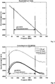
1 : Ergebnisse der Messung der Geschwindigkeit akustischer Oberflächenwellen in Abhängigkeit von der Frequenz auf dem Schichtsystem Hydrogel/(001)Si für die Abweichungen von der Ausbreitungsrichtung [110] um 0° und 30°, zugehörig zum Beispiel 1, -
2 : Ergebnisse der Messung der Geschwindigkeit akustischer Oberflächenwellen in Abhängigkeit von der Frequenz auf dem Schichtsystem SiO2/(001 )Si für die Abweichungen von der Ausbreitungsrichtung [110] um 0°, 30° und 45°, zugehörig zum Beispiel 2, -
3 : Ergebnisse der Messung der Geschwindigkeit akustischer Oberflächenwellen in Abhängigkeit von der Frequenz auf dem Schichtsystem RuAI/(001)Si für die Ausbreitungsrichtung [110], zugehörig zum Beispiel 3, -
4 : Ergebnisse der Messung der Geschwindigkeit akustischer Oberflächenwellen in Abhängigkeit von der Frequenz auf dem Schichtsystem AIN/(001)Si für die Abweichungen von der Ausbreitungsrichtung [110] um 0°, 30° und 45°, zugehörig zum Beispiel 4.
-
1 : Results of the measurement of the velocity of surface acoustic waves as a function of the frequency on the layer system hydrogel / (001) Si for the deviations from the direction of propagation [110] by 0 ° and 30 °, belonging to example 1, -
2 : Results of the measurement of the speed of acoustic surface waves as a function of the frequency on the layer system SiO2 / (001) Si for the deviations from the direction of propagation [110] by 0 °, 30 ° and 45 °, belonging to example 2, -
3 : Results of the measurement of the velocity of surface acoustic waves as a function of the frequency on the layer system RuAI / (001) Si for the direction of propagation [110], belonging to example 3, -
4th : Results of the measurement of the velocity of surface acoustic waves as a function of the frequency on the layer system AIN / (001) Si for the deviations from the direction of propagation [110] by 0 °, 30 ° and 45 °, belonging to example 4.
Beispiel 1example 1
Dieses Ausführungsbeispiel bezieht sich auf
Das betrachtete Schichtsystem ist eine Hydrogelschicht auf (001) Silizium. Das Ziel ist, die elastischen Steifigkeiten c11 und c55 sowie die Dichte und Dicke der Schicht mit Hilfe eines Optimierungsverfahrens zu bestimmen, das berechnete Werte der Phasengeschwindigkeit akustischer Oberflächenwellen als Funktion der Frequenz an die entsprechenden gemessenen Werte anpasst (fittet). Für eine erste Optimierung wurde ein Wert der Schichtdicke verwendet, der durch ein alternatives Verfahren mit 1,73 µm gemessen wurde. Die Phasengeschwindigkeit akustischer Oberflächenwellen als Funktion der Frequenz, bezeichnet als Dispersionskurve, wurde mit Hilfe eines Gerätes, das das Verfahren, das im Stand der Technik als Lösung [1] erwähnt wird, benutzt, gemessen. Das Gerät kommt ohne piezoelektrische Eigenschaften des zu untersuchenden Schichtsystems aus, weil die akustischen Oberflächenwellen durch Laserimpulse angeregt und von einer piezoelektrischen Folie empfangen werden, die mit der Schneide des Detektorkeils des verwendeten Gerätes auf das Schichtsystem kontaktiert ist.The layer system under consideration is a hydrogel layer on (001) silicon. The aim is to determine the elastic stiffnesses c11 and c55 as well as the density and thickness of the layer with the help of an optimization process that adapts the calculated values of the phase velocity of surface acoustic waves as a function of the frequency to the corresponding measured values. For a first optimization, a value of the layer thickness was used, which was measured by an alternative method with 1.73 µm. The phase velocity of surface acoustic waves as a function of frequency, referred to as the dispersion curve, was measured with the aid of a device using the method mentioned in the prior art as solution [1]. The device works without the piezoelectric properties of the layer system to be examined, because the surface acoustic waves are excited by laser pulses and received by a piezoelectric film that is in contact with the cutting edge of the detector wedge of the device used on the layer system.
Die Optimierungsergebnisse mit vorgegebener Schichtdicke von 1,73 µm sind in Tabelle 1.1 für 5 Optimierungen zusammengefasst. Der gewählte Frequenzbereich ist 30 bis 110 MHz, dargestellt in
In Tabelle 1.2 werden 14 Optimierungsergebnisse derselben Hydrogelschicht auf (001) Silizium dargestellt, wobei zusätzlich zu Tabelle 1.1 auch die Schichtdicke zusammen mit den übrigen Parametern durch Optimierung bestimmt wurde. Für alle Optimierungen in Tabelle 1.2 wurden zufällige Startparameter gewählt. Trotzdem streuen die Parameter nur geringfügig. Die Schichtdicke wird näherungsweise zu 1,795 µm bestimmt. Die Eigenschaftswerte in den Tabellen 1.1 und 1.2 liegen ziemlich dicht beieinander. Die Differenzen liegen im einstelligen Prozentbereich. Unabhängig davon, welche der beiden Optimierungen die kleineren Fehler liefert, wird gefunden, dass das beschriebene Verfahren zur Bestimmung von Eigenschaften mindestens eines Schichtsystems auf einem Festkörpersubstrat unter bestimmten Voraussetzungen in der Lage ist, neben den Schichteigenschaften c11, c55 und Dichte auch die Schichtdicke zu bestimmen. Voraussetzung dafür ist, dass der parabolische Anteil an den gemessenen Kurven der Geschwindigkeit akustischer Oberflächenwellen in Abhängigkeit von der Frequenz möglichst groß ist, andere störende nichtlineare Anteile wie in
Schichtsystem Hydroge!/(001)Si; die Schichtdicke wurde alternativ bestimmt (E= Elastizitätsmodul).
Variable: c11, c55, Dichte
Konstante: Schichtdicke = 1,73 µm
Genutzter Frequenzbereich: 30... 110 MHz
40-facher Punktabstand im Vergleich zur Messung
Ergebnisse von 5 Optimierungen mit zufällig gewählten Startparametern
Tabelle 1.2
Variable: c11, c55, Dichte, Schichtdicke
Konstante: keine
Frequenzbereich: 30... 110 MHz
40-facher Punktabstand im Vergleich zur Messung
Ergebnisse von 14 Optimierungen mit zufällig gewählten StartparameternLayer system Hydroge! / (001) Si; the layer thickness was determined alternatively (E = modulus of elasticity).
Variable: c11, c55, density
Constant: layer thickness = 1.73 µm
Frequency range used: 30 ... 110 MHz
40 times the point spacing compared to the measurement
Results of 5 optimizations with randomly chosen starting parameters Table 1.2
Variables: c11, c55, density, layer thickness
Constant: none
Frequency range: 30 ... 110 MHz
40 times the point spacing compared to the measurement
Results of 14 optimizations with randomly chosen starting parameters
Beispiel 2Example 2
Dieses Ausführungsbeispiel bezieht sich auf
Das betrachtete Schichtsystem ist eine SiO2-Schicht auf (001)Silizium. Das Ziel ist, die elastischen Steifigkeiten c11 und c55 sowie die Dichte und Dicke der Schicht mit Hilfe eines Optimierungsverfahrens zu bestimmen, das berechnete Werte der Phasengeschwindigkeit akustischer Oberflächenwellen als Funktion der Frequenz an die entsprechenden gemessenen Werte anpasst (fittet). Für eine erste Optimierung wurde ein Wert der Schichtdicke verwendet, der durch ein alternatives Verfahren mit 0,785 µm gemessen wurde. Die Phasengeschwindigkeit akustischer Oberflächenwellen als Funktion der Frequenz, bezeichnet als Dispersionskurve, wurde mit Hilfe eines Gerätes nach DIN 15042-1:2006-06 gemessen. Das Gerät wurde im Beispiel 1 kurz beschrieben.The layer system considered is an SiO 2 layer on (001) silicon. The aim is to determine the elastic stiffnesses c11 and c55 as well as the density and thickness of the layer with the help of an optimization process determine which adapts calculated values of the phase velocity of surface acoustic waves as a function of frequency to the corresponding measured values. For a first optimization, a value of the layer thickness was used, which was measured by an alternative method with 0.785 µm. The phase velocity of surface acoustic waves as a function of the frequency, referred to as the dispersion curve, was measured using a device in accordance with DIN 15042-1: 2006-06. The device was briefly described in Example 1.
Die Optimierungsergebnisse mit vorgegebener Schichtdicke von 0,785 µm sind in Tabelle 2.1 für 5 Optimierungen zusammengefasst. Der Frequenzbereich ist mit 60 bis 270 MHz gewählt. Obwohl für jede Ergebniszeile in Tabelle 2.1 zufällig gewählte Startparameter für die Optimierung verwendet wurden, streuen die Werte für c11, c55 und Dichte der Schicht nur geringfügig.The optimization results with a given layer thickness of 0.785 µm are summarized in Table 2.1 for 5 optimizations. The frequency range is selected to be 60 to 270 MHz. Although randomly selected starting parameters were used for the optimization for each result line in Table 2.1, the values for c11, c55 and density of the layer only scatter slightly.
In Tabelle 2.2 werden 10 Optimierungsergebnisse derselben SiO2-Schicht auf (001)Silizium präsentiert, wobei zusätzlich zu Tabelle 2.1 auch die Schichtdicke zusammen mit den übrigen Parametern durch Optimierung bestimmt wurde. Für alle Optimierungen in den Tabellen 2.1 und 2.2 wurden zufällige Startparameter gewählt. Trotzdem streuen die Parameter nur geringfügig. Allerdings unterscheiden sich die Werte in beiden Tabellen deutlich. Die Werte in Tabelle 2.1 sind offensichtlich zuverlässiger als die in Tabelle 2.2, weil die in Tabelle 2.1 angegebenen Werte der Dichte der SiO2-Schicht mit näherungsweise 2,18 dem bekannten Wert für amorphes SiO2 (Quarzglas) von 2,20 recht nahe kommen. Das beschriebene Verfahren zur Bestimmung von Eigenschaften mindestens eines Schichtsystems auf einem Festkörpersubstrat bietet im vorliegenden Fall nicht die Voraussetzungen, neben den Schichteigenschaften c11, c55 und Dichte auch die Schichtdicke zu bestimmen. Voraussetzung dafür ist, dass der parabolische Anteil an den gemessenen Kurven der Geschwindigkeit akustischer Oberflächenwellen in Abhängigkeit von der Frequenz möglichst groß ist, andere nichtlineare Anteile jedoch sehr klein sind. Im Vergleich der hier beschriebenen Ausführungsbeispiele wird dieser Zusammenhang quantitativ beschrieben.
Tabelle 2.1
Schichtsystem SiO2/(001)Si, Schichtdicke alternativ bestimmt
Variable: c11, c55 Dichte
Konstante: Schichtdicke = 0,785 µm
Genutzter Frequenzbereich: 60...270 MHz
40-facher Punktabstand im Vergleich zur Messung
Ergebnisse von 5 Optimierungen mit zufällig gewählten Startparametern
Tabelle 2.2
Schichtdicke zusammen mit den übrigen Parametern durch Optimierung bestimmt, Variable: c11, c55, Dichte, Schichtdicke
Konstante: keine
Frequenzbereich: 60...270 MHz
40-facher Punktabstand im Vergleich zur Messung
Ergebnisse von 10 Optimierungen mit zufällig gewählten StartparameternIn Table 2.2, 10 optimization results of the same SiO 2 layer on (001) silicon are presented, with the layer thickness and the other parameters also being determined by optimization in addition to Table 2.1. For all optimizations in Tables 2.1 and 2.2, random starting parameters were chosen. Nevertheless, the parameters only scatter slightly. However, the values in both tables differ significantly. The values in table 2.1 are obviously more reliable than those in table 2.2 because the values given in table 2.1 for the density of the SiO 2 layer with approximately 2.18 come very close to the known value for amorphous SiO 2 (quartz glass) of 2.20 . In the present case, the described method for determining properties of at least one layer system on a solid substrate does not offer the prerequisites for determining the layer thickness in addition to the layer properties c11, c55 and density. The prerequisite for this is that the parabolic component of the measured curves of the speed of acoustic surface waves as a function of the frequency is as large as possible, while other non-linear components are very small. This relationship is described quantitatively in a comparison of the exemplary embodiments described here. Table 2.1
Layer system SiO 2 / (001) Si, layer thickness determined alternatively
Variable: c11, c55 density
Constant: layer thickness = 0.785 µm
Frequency range used: 60 ... 270 MHz
40 times the point spacing compared to the measurement
Results of 5 optimizations with randomly chosen starting parameters Table 2.2
Layer thickness together with the other parameters determined by optimization, variables: c11, c55, density, layer thickness
Constant: none
Frequency range: 60 ... 270 MHz
40 times the point spacing compared to the measurement
Results of 10 optimizations with randomly chosen starting parameters
Beispiel 3Example 3
Dieses Ausführungsbeispiel bezieht sich auf
Das betrachtete Schichtsystem ist eine RuAI-Schicht auf (001)Silizium. Diese Schicht wurde als Schichtsystem aus mehreren Aluminium- und Rutheniumschichten hergestellt und anschließend durch eine thermische Behandlung, zum Beispiel Tempern, homogenisiert.The layer system considered is a RuAI layer on (001) silicon. This layer was produced as a layer system of several aluminum and ruthenium layers and then homogenized by a thermal treatment, for example tempering.
Die Optimierungsergebnisse mit vorgegebener Schichtdicke von 0,22 µm sind in Tabelle 3 für 2 Optimierungen zusammengefasst. Der Frequenzbereich ist mit 70 bis 250 MHz gewählt.
Tabelle 3
RuAI/(001)[110]Si, getempert bei 900°C, Dicke: Summe aller Einzelschichtdicken, Variable: c11, c55, Dichte
Konstante: Schichtdicke = 0,22 µm
Genutzter Frequenzbereich: 70...250 MHz
40-facher Punktabstand im Vergleich zur Messung
Ergebnisse von 2 Optimierungen mit zufällig gewählten StartparameternThe optimization results with a given layer thickness of 0.22 µm are summarized in Table 3 for 2 optimizations. The frequency range is selected to be 70 to 250 MHz. Table 3
RuAI / (001) [110] Si, annealed at 900 ° C, thickness: sum of all individual layer thicknesses, variables: c11, c55, density
Constant: layer thickness = 0.22 µm
Frequency range used: 70 ... 250 MHz
40 times the point spacing compared to the measurement
Results of 2 optimizations with randomly chosen starting parameters
Beispiel 4Example 4
Dieses Ausführungsbeispiel bezieht sich auf
Das betrachtete Schichtsystem ist eine AIN-Schicht auf (001)Silizium. Das Ziel ist, die elastischen Steifigkeiten c11 und c55 sowie die Dichte und Dicke der Schicht mit Hilfe eines Optimierungsverfahrens zu bestimmen, das berechnete Werte der Phasengeschwindigkeit akustischer Oberflächenwellen als Funktion der Frequenz an die entsprechenden gemessenen Werte anpasst (fittet). Die Phasengeschwindigkeit akustischer Oberflächenwellen als Funktion der Frequenz, bezeichnet als Dispersionskurve, wurde mit Hilfe eines Gerätes nach DIN 15042-1:2006-06 gemessen. Das Gerät ist im Beispiel 1 kurz beschrieben worden.The layer system under consideration is an AlN layer on (001) silicon. The aim is to determine the elastic stiffnesses c11 and c55 as well as the density and thickness of the layer with the help of an optimization process determine which adapts calculated values of the phase velocity of surface acoustic waves as a function of frequency to the corresponding measured values. The phase velocity of surface acoustic waves as a function of the frequency, referred to as the dispersion curve, was measured using a device in accordance with DIN 15042-1: 2006-06. The device has been briefly described in Example 1.
In Tabelle 4 werden 10 Optimierungsergebnisse der AIN-Schicht auf (001)Silizium präsentiert, wobei auch die Schichtdicke zusammen mit den übrigen Parametern durch Optimierung bestimmt wurde. Für alle Optimierungen in Tabelle 4 wurden zufällige Startparameter gewählt. Trotzdem streuen die Parameter nur geringfügig. Das beschriebene Verfahren zur Bestimmung von Eigenschaften mindestens eines Schichtsystems auf einem Festkörpersubstrat bietet im vorliegenden Fall die Voraussetzungen, neben den Schichteigenschaften c11, c55 und Dichte auch die Schichtdicke zu bestimmen. Voraussetzung dafür ist, dass der parabolische Anteil an den gemessenen Kurven der Geschwindigkeit akustischer Oberflächenwellen in Abhängigkeit von der Frequenz möglichst groß ist, andere nichtlineare Anteile jedoch sehr klein sind. Die Kurven in
AIN/(001)Si
Variable: c11, c55, Dichte, Dicke
Konstante: keine
Genutzter Frequenzbereich: 50... 500 MHz
30-facher Punktabstand im Vergleich zur Messung
Ergebnisse von 10 Optimierungen mit zufällig gewählten StartparameternTable 4 shows 10 optimization results of the AlN layer on (001) silicon, the layer thickness also being determined by optimization together with the other parameters. For all optimizations in Table 4 random starting parameters were chosen. Nevertheless, the parameters only scatter slightly. In the present case, the described method for determining properties of at least one layer system on a solid substrate offers the prerequisites for determining the layer thickness in addition to the layer properties c11, c55 and density. The prerequisite for this is that the parabolic component of the measured curves of the speed of acoustic surface waves as a function of the frequency is as large as possible, while other non-linear components are very small. The curves in
AIN / (001) Si
Variable: c11, c55, density, thickness
Constant: none
Frequency range used: 50 ... 500 MHz
30 times the point spacing compared to the measurement
Results of 10 optimizations with randomly chosen starting parameters
Vergleich der Ausführungsbeispiele 1 bis 3 hinsichtlich parabolischer Anteile an den DispersionskurvenComparison of the embodiments 1 to 3 with regard to parabolic components in the dispersion curves
Als Maß für die parabolischen Anteile an den Dispersionskurven wird die mittlere 2. Ableitung der Geschwindigkeit nach der Frequenz als die mittlere Krümmung dieser Kurven im für die Optimierung verwendeten Frequenzbereich benutzt. Die entsprechenden Werte für die betrachteten Schichtsysteme sind in Tabelle 5 enthalten. Es ist daraus ersichtlich, dass das Schichtsystem Hydrogel/(001)[110]Si dem Betrag nach am stärksten gekrümmt und von unten konkav ist, was auch aus
Zusammenfassend lässt sich feststellen, dass sowohl ein höherer parabolischer Anteil an den Dispersionskurven der Geschwindigkeit als auch die Einbeziehung von mehr als einer Ausbreitungsrichtung in die Messung der Dispersionskurven förderlich sind für die genauere Bestimmung und/oder eine größere Anzahl von unabhängig voneinander bestimmbaren Schichteigenschaften.
Tabelle 5
Vergleich der mittleren 2. Ableitungen der Geschwindigkeit nach der Frequenz als Maß für die mittleren Krümmungen der Kurven für die Schichtsysteme Hydrogel/(001)[110]Si, AIN//(001)[110]Si, SiO2/(001)[110]Si und RuAI/(001)[110]Si aus
ZITATE ENTHALTEN IN DER BESCHREIBUNG QUOTES INCLUDED IN THE DESCRIPTION
Diese Liste der vom Anmelder aufgeführten Dokumente wurde automatisiert erzeugt und ist ausschließlich zur besseren Information des Lesers aufgenommen. Die Liste ist nicht Bestandteil der deutschen Patent- bzw. Gebrauchsmusteranmeldung. Das DPMA übernimmt keinerlei Haftung für etwaige Fehler oder Auslassungen.This list of the documents listed by the applicant was generated automatically and is included solely for the better information of the reader. The list is not part of the German patent or utility model application. The DPMA assumes no liability for any errors or omissions.
Zitierte Nicht-PatentliteraturNon-patent literature cited
- DIN EN 15042-1:2006-06 [0003]DIN EN 15042-1: 2006-06 [0003]
- Tsung-Tsong Wu, Yung-Yu Chen und Guo-Tsai Huang, „Evaluation of properties of sub-micrometer thin films using high frequency ultrasonic waves“, in Proc.11th International Congress on Fracture (ICF) 2005, Vol. 5, S.3769 [0004]Tsung-Tsong Wu, Yung-Yu Chen and Guo-Tsai Huang, “Evaluation of properties of sub-micrometer thin films using high frequency ultrasonic waves”, in Proc. 11th International Congress on Fracture (ICF) 2005, Vol. 5, p .3769 [0004]
- F. S. Hickernell and T. S. Hickernell, „Surface Acoustic Wave Characterization of PECVD Films on Gallium Arsenide“ in IEEE Transactions on Ultrasonics, Ferroelectrics, and Frequency Control, Vol. 42, No. 3, May 1995 [0005]F. S. Hickernell and T. S. Hickernell, "Surface Acoustic Wave Characterization of PECVD Films on Gallium Arsenide" in IEEE Transactions on Ultrasonics, Ferroelectrics, and Frequency Control, Vol. 42, No. May 3, 1995 [0005]
- M. Knapp, A. M. Lomonossov, P.Warkentin, P. M. Jäger, W. Ruile, H.-P. Kirschner, M. Honal, I. Bleyl, A. P. Mayer, and L. M Reindl, „Accurate Characterization of SiO2 Thin Films Using Surface Acoustic Waves“, IEEE Transactions on Ultrasonics, Ferroelectrics, and Frequency Control, Vol. 62, No. 4, April 2015 [0006]M. Knapp, AM Lomonossov, P.Warkentin, PM Jäger, W. Ruile, H.-P. Kirschner, M. Honal, I. Bleyl, AP Mayer, and L. M Reindl, "Accurate Characterization of SiO 2 Thin Films Using Surface Acoustic Waves", IEEE Transactions on Ultrasonics, Ferroelectrics, and Frequency Control, Vol. 62, no. April 4, 2015 [0006]
Claims (22)
Priority Applications (1)
| Application Number | Priority Date | Filing Date | Title |
|---|---|---|---|
| DE102019106510.0A DE102019106510B4 (en) | 2019-03-14 | 2019-03-14 | Method for determining the properties of layers in layer systems |
Applications Claiming Priority (1)
| Application Number | Priority Date | Filing Date | Title |
|---|---|---|---|
| DE102019106510.0A DE102019106510B4 (en) | 2019-03-14 | 2019-03-14 | Method for determining the properties of layers in layer systems |
Publications (2)
| Publication Number | Publication Date |
|---|---|
| DE102019106510A1 true DE102019106510A1 (en) | 2020-09-17 |
| DE102019106510B4 DE102019106510B4 (en) | 2021-02-25 |
Family
ID=72240978
Family Applications (1)
| Application Number | Title | Priority Date | Filing Date |
|---|---|---|---|
| DE102019106510.0A Active DE102019106510B4 (en) | 2019-03-14 | 2019-03-14 | Method for determining the properties of layers in layer systems |
Country Status (1)
| Country | Link |
|---|---|
| DE (1) | DE102019106510B4 (en) |
Cited By (1)
| Publication number | Priority date | Publication date | Assignee | Title |
|---|---|---|---|---|
| CN116858939A (en) * | 2022-03-26 | 2023-10-10 | 天津大学 | Method for calculating dispersion curve of acoustic surface wave propagating in layered structure |
Citations (2)
| Publication number | Priority date | Publication date | Assignee | Title |
|---|---|---|---|---|
| US20050277111A1 (en) * | 2004-06-11 | 2005-12-15 | Ulvac, Inc. | Measuring method using surface acoustic wave device, and surface acoustic wave device and biosensor device |
| US20140007692A1 (en) * | 2011-07-28 | 2014-01-09 | Applied Sensor Research & Development Corporation | Surface acoustic wave monitor for deposition and analysis of ultra-thin films |
-
2019
- 2019-03-14 DE DE102019106510.0A patent/DE102019106510B4/en active Active
Patent Citations (2)
| Publication number | Priority date | Publication date | Assignee | Title |
|---|---|---|---|---|
| US20050277111A1 (en) * | 2004-06-11 | 2005-12-15 | Ulvac, Inc. | Measuring method using surface acoustic wave device, and surface acoustic wave device and biosensor device |
| US20140007692A1 (en) * | 2011-07-28 | 2014-01-09 | Applied Sensor Research & Development Corporation | Surface acoustic wave monitor for deposition and analysis of ultra-thin films |
Non-Patent Citations (5)
| Title |
|---|
| HICKERNELL, Fred S. ; HICKERNELL, Thomas S.: Surface acoustic wave characterization of PECVD films on gallium arsenide. In: IEEE Transactions on Ultrasonics, Ferroelectrics, and Frequency Control, Vol. 42, 1995, No. 3, S. 410-415. - ISSN 0885-3010 (P); 1525-8955 (E). DOI: 10.1109/58.384451. URL: https://ieeexplore.ieee.org/stamp/stamp.jsp?tp=&arnumber=384451 [abgerufen am 15.02.2018] * |
| KNAPP, Matthias [u.a.]: Accurate characterization of SiO2 thin films using surface acoustic waves. In: IEEE Transactions on Ultrasonics, Ferroelectrics and Frequency Control, Vol. 62, 2015, No. 4, S. 736-743. - ISSN 0885-3010 (P); 1525-8955 (E). DOI: 10.1109/TUFFC.2014.006921. URL: https://ieeexplore.ieee.org/stamp/stamp.jsp?tp=&arnumber=7081469 [abgerufen am 16.02.2018] * |
| Norm DIN EN 15042-1 2006-06-00. Schichtdickenmessung und Charakterisierung von Oberflächen mittels Oberflächenwellen - Teil 1: Leitfaden zur Bestimmung von elastischen Konstanten, Dichte und Dicke von Schichten mittels laserinduzierten Ultraschall-Oberflächenwellen; Deutsche Fassung EN 15042-1:2006. S. 1-26. URL: http://perinorm/Perinorm-Volltexte/2016-11_Grunbestand/CD21DE_02/9664284/9664284.pdf? [abgerufen am 07.05.2019] * |
| WU, Tsung-Tsong ; CHEN, Yung-Yu ; HUANG, Guo-Tsai: Evaluation of properties of sub-micrometer thin films using high frequency ultrasonic waves. In: 11th International Conference on Fracture 2005 (ICF11), 20-25 March 2005, Turin, Italy. Red Hook, NY : Curran Associates, Inc., Vol. 5, 2010, S. 3769-3774. - ISBN 978-1-61782-063-2 * |
| XIAO, X.; YOU, X.; YAO, S.: Theoretical study of mechanical properties of multi-layer ULSI interconnect dielectrics by surface acoustic wave method. In: Mircoelectr. J., Vol. 37, 2006, S. 1052-1055. * |
Cited By (1)
| Publication number | Priority date | Publication date | Assignee | Title |
|---|---|---|---|---|
| CN116858939A (en) * | 2022-03-26 | 2023-10-10 | 天津大学 | Method for calculating dispersion curve of acoustic surface wave propagating in layered structure |
Also Published As
| Publication number | Publication date |
|---|---|
| DE102019106510B4 (en) | 2021-02-25 |
Similar Documents
| Publication | Publication Date | Title |
|---|---|---|
| DE60008569T2 (en) | Acoustic interfacial wave filter, especially for wireless transmission systems | |
| DE4035240C2 (en) | Measuring and controlling the coating on a piezoelectric measuring crystal | |
| WO2002043243A1 (en) | Bulk acoustic wave filter | |
| EP0173864B1 (en) | Porous matching layer in an ultrasonic applicator | |
| DE3741698C2 (en) | ||
| DE112012000663B4 (en) | Method for determining a multilayer thin film deposition on a piezoelectric crystal | |
| DE112015002181T5 (en) | Piezoelectric oxide single crystal substrate | |
| WO2007085237A1 (en) | Electroacoustic component | |
| DE102019106510B4 (en) | Method for determining the properties of layers in layer systems | |
| DE3043776C2 (en) | Ultrasonic transducer for an imaging device | |
| EP1229514A2 (en) | Element with vibration-damping properties, material and method of manufacture | |
| DE3003961A1 (en) | METHOD AND DEVICE FOR DETECTING INHOMOGENICAL MAGNETIC MATERIALS | |
| DE102017122567A1 (en) | Apparatus and method for determining properties of conductive or dielectric layers | |
| DE4031639A1 (en) | DEVICE AND METHOD FOR UNIFORM POLARIZING OF PIEZOELECTRIC TRANSMITTERS | |
| EP1209458B1 (en) | Procedure for determining the noise level of an internal combustion engine | |
| DE102022126980B3 (en) | Method and device for determining properties of electrically conductive or dielectric layers in layer systems | |
| DE3221209C2 (en) | Device for examining bodies by scanning them with ultrasound | |
| DE19612925C1 (en) | Coated workpiece material characteristics testing system | |
| DE102018101095A1 (en) | Apparatus for receiving input signals and operating methods therefor | |
| DE19943072B4 (en) | Acoustic surface wave filter | |
| DE3004331A1 (en) | RESONATOR PLATE RECOVERABLE TO THICKNESS SHOCKING VIBRATIONS | |
| DE102020205160A1 (en) | AOW FILTER MANUFACTURING PROCESS and AOW FILTER | |
| DE3018080A1 (en) | ACOUSTIC SURFACE WAVE FILTER | |
| DE10017492A1 (en) | Passive surface vibration-damping coating for damping the vibrations of building components contains piezoelectric particles embedded in a matrix forming polymer for use without addition of conducting material | |
| DE102019131167A1 (en) | Method for active damping of vibrations during a process and device for active damping of vibrations |
Legal Events
| Date | Code | Title | Description |
|---|---|---|---|
| R012 | Request for examination validly filed | ||
| R016 | Response to examination communication | ||
| R018 | Grant decision by examination section/examining division | ||
| R020 | Patent grant now final |