DE102018006614B4 - Numerical control - Google Patents
Numerical control Download PDFInfo
- Publication number
- DE102018006614B4 DE102018006614B4 DE102018006614.3A DE102018006614A DE102018006614B4 DE 102018006614 B4 DE102018006614 B4 DE 102018006614B4 DE 102018006614 A DE102018006614 A DE 102018006614A DE 102018006614 B4 DE102018006614 B4 DE 102018006614B4
- Authority
- DE
- Germany
- Prior art keywords
- vibration
- unit
- instruction
- spindle
- oscillation
- Prior art date
- Legal status (The legal status is an assumption and is not a legal conclusion. Google has not performed a legal analysis and makes no representation as to the accuracy of the status listed.)
- Active
Links
Images


Classifications
-
- G—PHYSICS
- G05—CONTROLLING; REGULATING
- G05B—CONTROL OR REGULATING SYSTEMS IN GENERAL; FUNCTIONAL ELEMENTS OF SUCH SYSTEMS; MONITORING OR TESTING ARRANGEMENTS FOR SUCH SYSTEMS OR ELEMENTS
- G05B19/00—Program-control systems
- G05B19/02—Program-control systems electric
- G05B19/18—Numerical control [NC], i.e. automatically operating machines, in particular machine tools, e.g. in a manufacturing environment, so as to execute positioning, movement or co-ordinated operations by means of program data in numerical form
- G05B19/19—Numerical control [NC], i.e. automatically operating machines, in particular machine tools, e.g. in a manufacturing environment, so as to execute positioning, movement or co-ordinated operations by means of program data in numerical form characterised by positioning or contouring control systems, e.g. to control position from one programmed point to another or to control movement along a programmed continuous path
-
- G—PHYSICS
- G05—CONTROLLING; REGULATING
- G05B—CONTROL OR REGULATING SYSTEMS IN GENERAL; FUNCTIONAL ELEMENTS OF SUCH SYSTEMS; MONITORING OR TESTING ARRANGEMENTS FOR SUCH SYSTEMS OR ELEMENTS
- G05B19/00—Program-control systems
- G05B19/02—Program-control systems electric
- G05B19/18—Numerical control [NC], i.e. automatically operating machines, in particular machine tools, e.g. in a manufacturing environment, so as to execute positioning, movement or co-ordinated operations by means of program data in numerical form
-
- B—PERFORMING OPERATIONS; TRANSPORTING
- B23—MACHINE TOOLS; METAL-WORKING NOT OTHERWISE PROVIDED FOR
- B23Q—DETAILS, COMPONENTS, OR ACCESSORIES FOR MACHINE TOOLS, e.g. ARRANGEMENTS FOR COPYING OR CONTROLLING; MACHINE TOOLS IN GENERAL CHARACTERISED BY THE CONSTRUCTION OF PARTICULAR DETAILS OR COMPONENTS; COMBINATIONS OR ASSOCIATIONS OF METAL-WORKING MACHINES, NOT DIRECTED TO A PARTICULAR RESULT
- B23Q15/00—Automatic control or regulation of feed movement, cutting velocity or position of tool or work
- B23Q15/007—Automatic control or regulation of feed movement, cutting velocity or position of tool or work while the tool acts upon the workpiece
- B23Q15/013—Control or regulation of feed movement
-
- G—PHYSICS
- G05—CONTROLLING; REGULATING
- G05B—CONTROL OR REGULATING SYSTEMS IN GENERAL; FUNCTIONAL ELEMENTS OF SUCH SYSTEMS; MONITORING OR TESTING ARRANGEMENTS FOR SUCH SYSTEMS OR ELEMENTS
- G05B2219/00—Program-control systems
- G05B2219/30—Nc systems
- G05B2219/45—Nc applications
- G05B2219/45044—Cutting
-
- G—PHYSICS
- G05—CONTROLLING; REGULATING
- G05B—CONTROL OR REGULATING SYSTEMS IN GENERAL; FUNCTIONAL ELEMENTS OF SUCH SYSTEMS; MONITORING OR TESTING ARRANGEMENTS FOR SUCH SYSTEMS OR ELEMENTS
- G05B2219/00—Program-control systems
- G05B2219/30—Nc systems
- G05B2219/49—Nc machine tool, till multiple
- G05B2219/49055—Remove chips from probe, tool by vibration
-
- G—PHYSICS
- G05—CONTROLLING; REGULATING
- G05B—CONTROL OR REGULATING SYSTEMS IN GENERAL; FUNCTIONAL ELEMENTS OF SUCH SYSTEMS; MONITORING OR TESTING ARRANGEMENTS FOR SUCH SYSTEMS OR ELEMENTS
- G05B2219/00—Program-control systems
- G05B2219/30—Nc systems
- G05B2219/49—Nc machine tool, till multiple
- G05B2219/49384—Control of oscillatory movement like filling a weld, weaving
Landscapes
- Engineering & Computer Science (AREA)
- Human Computer Interaction (AREA)
- Manufacturing & Machinery (AREA)
- Physics & Mathematics (AREA)
- General Physics & Mathematics (AREA)
- Automation & Control Theory (AREA)
- Mechanical Engineering (AREA)
- Numerical Control (AREA)
- Automatic Control Of Machine Tools (AREA)
- Turning (AREA)
Abstract
Numerische Steuerung (100), die konfiguriert ist, um ein Schwingungsschneiden auszuführen, indem eine Schwingungsanweisung einer Positionsanweisung überlagert wird, wobei die Schwingungsanweisung das Vorgeben einer Schwingungsfrequenz und einer Schwingungsamplitude umfasst, wobei die numerische Steuerung (100) umfasst:eine Einheit zum Generieren einer Positionsanweisung (110), die konfiguriert ist, um die Positionsanweisung zu generieren;eine Einheit zum Generieren einer Schwingungsanweisung (120), die konfiguriert ist, um die Schwingungsanweisung zu generieren;eine Einheit zum Steuern einer Positionsgeschwindigkeit (130), die konfiguriert ist, um die Positionsanweisung und die Schwingungsanweisung zu addieren, um eine synthetisierte Anweisung zu generieren; undeine Stromsteuereinheit (140), die konfiguriert ist, um die Bewegung eines Werkzeugs oder die Rotation einer Spindel zu steuern, wobeidie Einheit zum Generieren einer Schwingungsanweisung (120) umfassteine Einheit zum Berechnen eines Nachlauffehlers (123), die konfiguriert ist, um einen tatsächlichen Winkel und einen idealen Winkel der Spindel zu erzielen und zu berechnen, undeine Einheit zum Neuberechnen einer Frequenz (124), die konfiguriert ist, um die Schwingungsfrequenz oder eine Drehzahl (S) der Spindel basierend auf dem tatsächlichen Winkel und dem idealen Winkel neu zu berechnen, unddie Stromsteuereinheit (140) die Bewegung des Werkzeugs oder die Rotation der Spindel gemäß der neu berechneten Schwingungsfrequenz oder Drehzahl (S) der Spindel steuert.A numerical controller (100) configured to perform vibration cutting by superimposing a vibration command on a position command, the vibration command comprising specifying a vibration frequency and a vibration amplitude, the numerical controller (100) comprising:a unit for generating a position command (110) configured to generate the position instruction;a unit for generating an oscillation instruction (120) configured to generate the oscillation instruction;a unit for controlling a position speed (130) configured to adding the position instruction and the vibration instruction to generate a synthesized instruction; and a power control unit (140) configured to control the movement of a tool or the rotation of a spindle, the unit for generating a vibration instruction (120) comprising a unit for calculating a tracking error (123) configured to an actual angle and to obtain and calculate an ideal angle of the spindle, anda frequency recalculation unit (124) configured to recalculate the oscillation frequency or a rotation speed (S) of the spindle based on the actual angle and the ideal angle, and the power control unit (140) controls the movement of the tool or the rotation of the spindle according to the newly calculated oscillation frequency or speed (S) of the spindle.
Description
HINTERGRUND DER ERFINDUNGBACKGROUND OF THE INVENTION
Gebiet der ErfindungField of invention
Die vorliegende Erfindung betrifft eine numerische Steuerung und betrifft genauer gesagt eine numerische Steuerung, die ein Schwingungsschneiden ausführen und dabei eine Spanzerkleinerungsfähigkeit aufrechterhalten kann.The present invention relates to a numerical controller, and more particularly relates to a numerical controller that can perform oscillation cutting while maintaining chip-reducing capability.
Beschreibung der verwandten TechnikDescription of the related technique
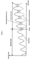
Ein Bearbeitungsverfahren, um ein Werkzeug in einer Schneidrichtung in Schwingung zu versetzen und Späne zu zerkleinern, wird als Schwingungsschneiden bezeichnet.A machining method to vibrate a tool in a cutting direction and crush chips is called vibration cutting.
Eine herkömmliche numerische Steuerung führt das Schwingungsschneiden aus, indem sie die folgende Schwingungsanweisung einer Bearbeitungsanweisung überlagert.![]()
![]()
In der obigen Gleichung wird K × F/2 als Schwingungsamplitude bezeichnet, und 2n × S/60 × I wird als Schwingungsfrequenz bezeichnet. Zudem stellt F den Vorschub pro Umdrehung [mm/U] dar, S stellt eine Spindeldrehzahl [min-1] dar, t stellt eine Zeit [s] dar, K stellt einen Multiplikationsfaktor der Schwingungsamplitude dar, und I stellt einen Multiplikationsfaktor der Schwingungsfrequenz dar (die Anzahl der Schwingungen pro Rotation).In the above equation, K × F/2 is called the oscillation amplitude, and 2n × S/60 × I is called the oscillation frequency. In addition, F represents the feed per revolution [mm/rev], S represents a spindle speed [min -1 ], t represents a time [s], K represents a multiplication factor of the oscillation amplitude, and I represents a multiplication factor of the oscillation frequency (the number of oscillations per rotation).
Wenn eine Schwingungsanweisung (Sinuswelle) zu einer Bearbeitungsanweisung addiert wird, fährt ein Werkzeug mit der Bearbeitung fort, während es eine Hin- und Herbewegung in einer Vorschubrichtung wiederholt. Wenn sich in diesem Fall eine Werkzeugbahn einer ersten Rotation und eine Werkzeugbahn einer zweiten Rotation überlappen und die Bearbeitung mit einem Fehlschlag endet, werden die Späne zerkleinert.
Wenn man sich auf eine Werkzeugposition konzentriert, überlappt sich die Werkzeugbahn der zweiten Rotation mit der Werkzeugbahn der ersten Rotation 4,5mal pro Rotation (in
Gemäß der japanischen Patent-Auslegeschrift
Selbst wenn ein Schwingungsschneiden ausgeführt wird, wie in der japanischen Patent-Auslegeschrift
Weiteren Stand der Technik beschreibt die Druckschrift
KURZDARSTELLUNG DER ERFINDUNGSUMMARY OF THE INVENTION
Die vorliegende Erfindung wurde erdacht, um das obige Problem zu lösen. Eine Aufgabe der vorliegenden Erfindung besteht darin, eine numerische Steuerung bereitzustellen, die, selbst wenn ein Nachlauffehler zwischen einer Spindelrotation und einer Schwingungsbetätigung vorkommt, ein Schwingungsschneiden ausführen und dabei die Spanzerkleinerungsfähigkeit aufrechterhalten kann.The present invention was conceived to solve the above problem. An object of the present invention is to provide a numerical controller which, even when a tracking error occurs between spindle rotation and oscillation operation, can perform oscillation cutting while maintaining chip-crushing capability.
Gelöst wird die Aufgabe durch eine numerische Steuerung mit den Merkmalen des Patentanspruchs 1.Diese numerische Steuerung ist konfiguriert, um das Schwingungsschneiden auszuführen, indem sie eine Schwingungsanweisung einer Positionsanweisung überlagert, wobei die Schwingungsanweisung das Vorgeben einer Schwingungsfrequenz und einer Schwingungsamplitude umfasst, und umfasst: eine Einheit zum Generieren einer Positionsanweisung, die konfiguriert ist, um die Positionsanweisung zu generieren; eine Einheit zum Generieren einer Schwingungsanweisung, die konfiguriert ist, um die Schwingungsanweisung zu generieren; eine Einheit zum Steuern einer Positionsgeschwindigkeit, die konfiguriert ist, um die Positionsanweisung und die Schwingungsanweisung zu addieren, um eine synthetisierte Anweisung zu generieren; und eine Stromsteuereinheit, die konfiguriert ist, um die Bewegung eines Werkzeugs oder die Rotation einer Spindel zu steuern, und die Einheit zum Generieren einer Schwingungsanweisung umfasst eine Einheit zum Berechnen eines Nachlauffehlers, die konfiguriert ist, um einen tatsächlichen Winkel und einen idealen Winkel der Spindel zu erzielen und zu berechnen, und eine Einheit zum Neuberechnen einer Frequenz, die konfiguriert ist, um die Schwingungsfrequenz oder eine Drehzahl der Spindel basierend auf dem tatsächlichen Winkel und dem idealen Winkel neu zu berechnen, und die Stromsteuereinheit steuert die Bewegung des Werkzeugs oder die Rotation der Spindel gemäß der neu berechneten Schwingungsfrequenz oder Drehzahl der Spindel.The task is solved by a numerical control having the features of patent claim 1. This numerical control is configured to carry out the oscillatory cutting by superimposing a oscillation instruction on a position instruction, the oscillation instruction comprising specifying a oscillation frequency and a oscillation amplitude, and comprising: a Position instruction generating unit configured to generate the position instruction; an oscillation instruction generating unit configured to generate the oscillation instruction; a position velocity control unit configured to add the position instruction and the vibration instruction to generate a synthesized instruction; and a power control unit configured to control movement of a tool or rotation of a spindle, and the unit for generating a vibration instruction includes a unit for calculating a tracking error configured to determine an actual angle and an ideal angle of the spindle to achieve and calculate, and a frequency recalculation unit configured to recalculate the oscillation frequency or a rotation speed of the spindle based on the actual angle and the ideal angle, and the power control unit controls the movement of the tool or the rotation the spindle according to the newly calculated oscillation frequency or speed of the spindle.
Bei der numerischen Steuerung gemäß einer Ausführungsform der vorliegenden Erfindung umfasst die Einheit zum Generieren einer Schwingungsanweisung ferner eine Einheit zum Neuberechnen einer Amplitude, die konfiguriert ist, um die Schwingungsamplitude neu zu berechnen, so dass sich die Werkzeugbahnen überlappen, und die Stromsteuereinheit steuert ferner die Bewegung des Werkzeugs gemäß der neu berechneten Schwingungsamplitude.In the numerical control according to an embodiment of the present invention, the vibration instruction generating unit further includes an amplitude recalculation unit configured to recalculate the vibration amplitude so that the tool paths overlap, and the power control unit further controls the movement of the tool according to the newly calculated vibration amplitude.
Die vorliegende Erfindung kann eine numerische Steuerung bereitstellen, die, selbst wenn ein Nachlauffehler zwischen einer Spindelrotation und einer Schwingungsbetätigung vorkommt, das Schwingungsschneiden ausführen und dabei eine Spanzerkleinerungsfähigkeit aufrechterhalten kann.The present invention can provide a numerical controller that can perform vibration cutting while maintaining chip-reducing capability even when a tracking error occurs between spindle rotation and vibration operation.
KURZE BESCHREIBUNG DER ZEICHNUNGENBRIEF DESCRIPTION OF THE DRAWINGS
Die zuvor erwähnten und andere Aufgaben und Kennzeichen der vorliegenden Erfindung werden aus der Beschreibung der folgenden Ausführungsform angesichts der beiliegenden Zeichnungen besser hervorgehen. Es zeigen:
-
1 eine Ansicht zum Erklären eines Prinzips des herkömmlichen Schwingungsschneidens; -
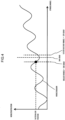
2 eine Ansicht zum Erklären eines Problems, das durch einen Nachlauffehler des herkömmlichen Schwingungsschneidens verursacht wird; -
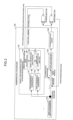
3 ein Blockdiagramm zum Erklären einer Konfiguration einer numerischen Steuerung; -
4 eine Ansicht zum Erklären von Betätigungen einer Einheit zum Berechnen eines Nachlauffehlers und einer Einheit zum Neuberechnen einer Frequenz; -
5 eine Ansicht zum Erklären einer Betätigung einer Einheit zum Neuberechnen einer Amplitude; -
6 eine Ansicht zum Erklären einer Betätigung gemäß einer ersten Ausführungsform; und -
7 eine Ansicht zum Erklären einer Betätigung gemäß einer zweiten Ausführungsform.
-
1 a view for explaining a principle of conventional vibration cutting; -
2 a view for explaining a problem caused by a tracking error of conventional vibration cutting; -
3 a block diagram for explaining a configuration of a numerical controller; -
4 a view for explaining operations of a tracking error calculating unit and a frequency recalculating unit; -
5 a view for explaining an operation of an amplitude recalculating unit; -
6 a view for explaining an operation according to a first embodiment; and -
7 a view for explaining an operation according to a second embodiment.
AUSFÜHRLICHE BESCHREIBUNG DER BEVORZUGTEN AUSFÜHRUNGSFORMENDETAILED DESCRIPTION OF THE PREFERRED EMBODIMENTS
Die Ausführungsformen der vorliegenden Erfindung werden nachstehend mit Bezug auf die nachstehenden Zeichnungen beschrieben.The embodiments of the present invention will be described below with reference to the following drawings.
Eine herkömmliche Stromsteuereinheit steuert typischerweise nur einen Servomotor, der eine Werkzeugposition bewegt. Die Stromsteuereinheit 140 gemäß der vorliegenden Ausführungsform steuert jedoch einen Spindelmotor, der eine Spindel dreht. Ferner empfängt eine herkömmliche numerische Steuerung eine Positionsrückmeldung von dem Servomotor und korrigiert eine Positionsabweichung. Gemäß der vorliegenden Ausführungsform ist es jedoch auch möglich, ebenso eine Positionsabweichung zu korrigieren.A conventional power control unit typically only controls a servo motor that moves a tool position. However, the
Die Einheit 120 zum Generieren einer Schwingungsanweisung umfasst eine Frequenzberechnungseinheit 121, die eine geeignete Schwingungsfrequenz berechnet, um das Schwingungsschneiden auszuführen, eine Amplitudenberechnungseinheit 122, die ebenso eine Schwingungsamplitude berechnet, eine Einheit 123 zum Berechnen eines Nachlauffehlers, die einen Nachlauffehler basierend auf Rückmeldungen von einem Spindelmotor und einem Servomotor berechnet, eine Einheit 124 zum Neuberechnen einer Frequenz, die eine Frequenz gemäß dem Nachlauffehler korrigiert, und eine Einheit 125 zum Neuberechnen einer Amplitude, die eine Amplitude gemäß dem Nachlauffehler korrigiert. Die Einheit 124 zum Neuberechnen einer Frequenz und die Einheit 125 zum Neuberechnen einer Amplitude korrigieren die Frequenz und die Amplitude, so dass sich die Werkzeugbahnen überlappen, selbst wenn der Nachlauffehler vorkommt, so dass die Späne weiter zerkleinert werden.The vibration
Es wird eine Betätigung der numerischen Steuerung 100 mit Bezug auf
Zuerst interpretiert die Einheit zum Generieren einer Positionsanweisung 110 das Bearbeitungsprogramm und generiert eine Positionsanweisung. Die Einheit 120 zum Generieren einer Schwingungsanweisung generiert eine Schwingungsanweisung. In dieser Hinsicht bestimmen die Frequenzberechnungseinheit 121 und die Amplitudenberechnungseinheit 122 eine geeignete Schwingungsfrequenz und Schwingungsamplitude zum Zerkleinern von Spänen gemäß einer bekannten Technik, die beispielsweise in der japanischen Patent-Auslegeschrift
Die Einheit 123 zum Berechnen eines Nachlauffehlers empfängt eine Positions-(Winkel-) Rückmeldung von dem Spindelmotor und detektiert, dass sich eine Spindel einmal dreht (d.h. ein Rotationswinkel, der tatsächlich gleich eins ist (nachstehend als tatsächlicher Winkel bezeichnet), beträgt 360 Grad). Ferner empfängt die Einheit 123 zum Berechnen eines Nachlauffehlers die Rückmeldungen für Position und Geschwindigkeit von dem Servomotor und erzielt eine Position, die tatsächlich gleich eins ist (als tatsächliche Position bezeichnet), oder eine Geschwindigkeit, die tatsächlich gleich eins ist (als tatsächliche Geschwindigkeit bezeichnet), des Werkzeugs zu einem Zeitpunkt, zu dem sich die Spindel einmal dreht. Ferner berechnet die Einheit 123 zum Berechnen eines Nachlauffehlers einen Winkel, der ideal eins ist (als idealer Winkel bezeichnet), für die Spindel und zu der tatsächlichen Position oder der tatsächlichen Geschwindigkeit des Werkzeugs passt.The tracking error calculating unit 123 receives position (angle) feedback from the spindle motor and detects that a spindle rotates once (i.e., a rotation angle actually equal to one (hereinafter referred to as actual angle) is 360 degrees) . Further, the tracking error calculating unit 123 receives the position and speed feedbacks from the servo motor and obtains a position that is actually equal to one (referred to as actual position) or a speed that is actually equal to one (referred to as actual speed). , of the tool at a time when the spindle rotates once. Further, the tracking error calculating unit 123 calculates an angle that is ideally one (referred to as an ideal angle) for the spindle and matches the actual position or the actual speed of the tool.
Dies wird mit Bezug auf
Die Einheit 124 zum Neuberechnen einer Frequenz berechnet die Schwingungsfrequenz basierend auf dem tatsächlichen Winkel und dem idealen Winkel der Spindel neu. Beispielsweise wird der Multiplikationsfaktor I der Schwingungsfrequenz gemäß der folgenden Gleichung neu berechnet.
Wenn beispielsweise der aktuelle Multiplikationsfaktor I der Schwingungsfrequenz 2,5 beträgt, der ideale Winkel 340 Grad beträgt und der tatsächliche Winkel 370 Grad beträgt, wird der neu berechnete Multiplikationsfaktor I der Schwingungsfrequenz folgendermaßen berechnet![]()
![]()
Alternativ kann man statt der Anpassung des Multiplikationsfaktors I der Schwingungsfrequenz den Multiplikationsfaktor I der Schwingungsfrequenz behalten, und es kann eine Spindeldrehzahl S angepasst werden. Beispielsweise wird die Spindeldrehzahl S gemäß der folgenden Gleichung neu berechnet.![]()
![]()
Wenn beispielsweise die aktuelle Spindeldrehzahl S 200 ist, der ideale Winkel 340 Grad beträgt und der tatsächliche Winkel 370 Grad beträgt, wird die neu berechnete Spindeldrehzahl S folgendermaßen berechnet![]()
![]()
Wenn die neu berechnete Frequenz übernommen wird, berechnet die Einheit 125 zum Neuberechnen einer Amplitude eine Amplitude derart neu, dass sich die Werkzeugbahn der ersten Rotation und eine Werkzeugbahn der zweiten Rotation überlappen.When the recalculated frequency is adopted, the amplitude recalculating unit 125 recalculates an amplitude such that the tool path of the first rotation and a tool path of the second rotation overlap.
Die Bedeutung einer Neuberechnung der Amplitude wird mit Bezug auf
Zudem bewirkt nur die Verarbeitung der Neuberechnung der Frequenz, die durch die Einheit 124 zum Neuberechnen einer Frequenz ausgeführt wird, eine Überlappung der Werkzeugbahn der ersten Rotation und der Werkzeugbahn der zweiten Rotation. Wenn beispielsweise die Schwingungsamplitude von Beginn an einigermaßen hoch ist, reicht es aus, nur die Frequenz anzupassen. In diesem Fall muss die Einheit 125 zum Neuberechnen einer Amplitude die Amplitude nicht neu berechnen.In addition, only the frequency recalculation processing performed by the
Die Einheit 125 zum Neuberechnen einer Amplitude berechnet einen Multiplikationsfaktor K der Schwingungsamplitude beispielsweise gemäß der folgenden Vorgehensweise. Die Einheit 125 zum Neuberechnen einer Amplitude speichert die Werkzeugbahnen von zwei Rotationen der Spindel jederzeit in einem Zwischenspeicher. Die Einheit 125 zum Neuberechnen einer Amplitude bestimmt, ob eine Kurve, die durch die Werkzeugbahn der ersten Rotation angegeben wird, und eine Kurve, die durch die Werkzeugbahn der zweiten Rotation angegeben wird, einen Schnittpunkt aufweisen oder nicht. Wenn es einen Schnittpunkt gibt, wird der vorherige Multiplikationsfaktor K der Schwingungsamplitude ständig verwendet, ohne den Multiplikationsfaktor K der Schwingungsamplitude neu zu berechnen. Wenn es keinen Schnittpunkt gibt, wird eine Kurve, welche die Werkzeugbahn der zweiten Rotation angibt, korrigiert, um den aktuellen Multiplikationsfaktor K der Schwingungsamplitude zu erhöhen (indem beispielsweise der aktuelle Multiplikationsfaktor K der Schwingungsamplitude mit einem Multiplikationsfaktor multipliziert wird, der größer als die vorbestimmte 1 ist), um den neu berechneten Multiplikationsfaktor K der Schwingungsamplitude zu erzielen. Somit wird die Schwingungsamplitude korrigiert, so dass sie zunimmt. Auch für den neu berechneten Multiplikationsfaktor K der Schwingungsamplitude führt die Einheit 125 zum Neuberechnen einer Amplitude wiederholt eine Verarbeitung im Anschluss an die obige Bestimmungsverarbeitung aus, bis es einen Schnittpunkt gibt.The amplitude recalculation unit 125 calculates a multiplication factor K of the vibration amplitude, for example, according to the following procedure. The amplitude recalculation unit 125 stores the tool paths of two rotations of the spindle in a buffer at any time. The amplitude recalculating unit 125 determines whether a curve indicated by the tool path of the first rotation and a curve indicated by the tool path of the second rotation have an intersection or not. If there is an intersection point, the previous multiplication factor K of the oscillation amplitude is constantly used without recalculating the multiplication factor K of the oscillation amplitude. If there is no intersection, a curve indicating the tool path of the second rotation is corrected to increase the current vibration amplitude multiplication factor K (for example, by multiplying the current vibration amplitude multiplication factor K by a multiplication factor greater than the predetermined 1 is) to achieve the newly calculated multiplication factor K of the vibration amplitude. Thus, the oscillation amplitude is corrected so that it increases. Also for the newly calculated multiplication factor K of the vibration amplitude, the amplitude recalculating unit 125 repeatedly executes processing following the above determination processing until there is an intersection point.
Zudem wird durch die erste Bestimmungsverarbeitung bestimmt, dass es einen Schnittpunkt gibt, und der aktuelle Multiplikationsfaktor K der Schwingungsamplitude kann korrigiert werden, so dass er abnimmt (beispielsweise durch Multiplizieren des aktuellen Multiplikationsfaktors K der Schwingungsamplitude mit einem Multiplikationsfaktor, der kleiner als die vorbestimmte 1 ist). Ferner wird durch wiederholtes Ausführen der Korrektur- und Bestimmungsverarbeitung der minimale Multiplikationsfaktor K der Schwingungsamplitude, der den Schnittpunkt aufweist, erzielt. Im Allgemeinen ist, wenn eine Amplitude höher ist, eine Last eines Servomotors größer. Folglich ist es durch die Verwendung des minimalen Multiplikationsfaktors K der Schwingungsamplitude, die den Schnittpunkt aufweist, möglich, die Last des Servomotors zu minimieren.In addition, it is determined by the first determination processing that there is an intersection point, and the current vibration amplitude multiplication factor K may be corrected to decrease (for example, by multiplying the current vibration amplitude multiplication factor K by a multiplication factor smaller than the predetermined 1 ). Further, by repeatedly executing the correction and determination processing, the minimum multiplication factor K of the vibration amplitude having the intersection point is obtained. In general, when an amplitude is higher, a load of a servo motor is larger. Consequently, by using the minimum multiplication factor K of the vibration amplitude having the intersection point, it is possible to minimize the load on the servomotor.
Die Einheit 130 zum Steuern einer Positionsgeschwindigkeit addiert die Schwingungsanweisung, welche die neu berechnete Schwingungsfrequenz und die Schwingungsamplitude umfasst, zu der Positionsanweisung, um die synthetisierte Anweisung zu generieren. Die Stromsteuereinheit 140 steuert den Servomotor gemäß der synthetisierten Anweisung.The position
Wenn zudem die Einheit 124 zum Neuberechnen einer Frequenz die Spindeldrehzahl S anstelle des Frequenzmultiplikationsfaktors I anpasst, addiert die Einheit 130 zum Steuern einer Positionsgeschwindigkeit die Schwingungsanweisung, welche die neu berechnete Schwingungsamplitude umfasst, zu der Positionsanweisung, um die synthetisierte Anweisung zu generieren. Die Stromsteuereinheit 140 steuert den Servomotor gemäß der synthetisierten Anweisung. Zudem steuert die Stromsteuereinheit 140 den Spindelmotor gemäß der neu berechneten Spindeldrehzahl S.In addition, when the
Gemäß der vorliegenden Ausführungsform berechnet die Einheit 123 zum Berechnen eines Nachlauffehlers der Einheit 120 zum Generieren einer Schwingungsanweisung den tatsächlichen Winkel und den idealen Winkel der Spindel, und die Einheit 124 zum Neuberechnen einer Frequenz und die Einheit 125 zum Neuberechnen einer Amplitude berechnen die Frequenz und die Amplitude neu. Folglich werden, selbst wenn die Spindeldrehzahl schwankt und der Nachlauffehler vorkommt, die Werkzeugbahn der ersten Rotation und die Werkzeugbahn der zweiten Rotation automatisch angepasst, um sich wieder zu überlappen, und die Spanzerkleinerungsfähigkeit wird aufrechterhalten, ohne dass ein Benutzer eine Einstellung vornehmen müsste.According to the present embodiment, the tracking error calculating unit 123 of the oscillation
Erste AusführungsformFirst embodiment
Die erste Ausführungsform beschreibt eine typische Betätigung einer numerischen Steuerung 100 für den Fall, dass eine Spindelübersteuerung geändert wird.The first embodiment describes a typical operation of a
Es wird ein Fall, bei dem die Spindelübersteuerung von 150 % auf 100 % zu einem Zeitpunkt geändert wird, wie beispielsweise in
Wie zuvor beschrieben, verringert sich gemäß der vorliegenden Ausführungsform auch die Schwingungsfrequenz infolge einer Verringerung der Spindeldrehzahl, so dass eine Spanzerkleinerungsfähigkeit aufrechterhalten wird.As described above, according to the present embodiment, the vibration frequency also decreases due to a reduction in the spindle speed, so that chip-crushing capability is maintained.
Zweite AusführungsformSecond embodiment
Die zweite Ausführungsform beschreibt eine typische Betätigung einer numerischen Steuerung 100 für den Fall, dass eine konstante Steuerung der Umfangsgeschwindigkeit und ein Schwingungsschneiden gleichzeitig ausgeführt werden.The second embodiment describes a typical operation of a
Wie beispielsweise in
Wie zuvor beschrieben steigt gemäß der vorliegenden Ausführungsform die Schwingungsfrequenz auch infolge einer Erhöhung der Spindeldrehzahl an, so dass eine Spanzerkleinerungsfähigkeit aufrechterhalten wird.As described above, according to the present embodiment, the vibration frequency also increases due to an increase in the spindle speed, so that chip-breaking capability is maintained.
Die Ausführungsformen gemäß der vorliegenden Erfindung wurden zuvor beschrieben. Die vorliegende Erfindung ist jedoch nicht auf Beispiele der obigen Ausführungsformen eingeschränkt und kann in diversen Formen ausgeführt werden, indem optionale Änderungen hinzugefügt werden.The embodiments according to the present invention have been described above. However, the present invention is not limited to examples of the above embodiments and can be embodied in various forms by adding optional changes.
Beispielsweise haben die obigen Ausführungsformen Beispiele beschrieben, bei denen, wenn ein Nachlauffehler vorkommt, die Einheit 124 zum Neuberechnen einer Frequenz zuerst die Schwingungsfrequenz neu berechnet, und dann die Einheit 125 zum Neuberechnen einer Amplitude die Schwingungsamplitude neu berechnet.For example, the above embodiments have described examples in which, when a tracking error occurs, the
Die vorliegende Erfindung ist jedoch nicht darauf eingeschränkt und eine Anpassungsreihenfolge der Schwingungsfrequenz und der Schwingungsamplitude ist eine beliebige Reihenfolge. Beispielsweise kann die Einheit 125 zum Neuberechnen einer Amplitude zuerst die Schwingungsamplitude neu berechnen, und dann kann die Einheit 124 zum Neuberechnen einer Frequenz die Schwingungsfrequenz neu berechnen. Falls in diesem Fall eine Überlappung einer Werkzeugbahn einer ersten Rotation und einer Werkzeugbahn einer zweiten Rotation bewirkt werden kann, indem nur die Schwingungsamplitude angepasst wird, muss die Schwingungsfrequenz nicht unbedingt angepasst werden.However, the present invention is not limited to this, and an adjustment order of the oscillation frequency and the oscillation amplitude is an arbitrary order. For example, the amplitude recalculation unit 125 may first recalculate the oscillation amplitude, and then the
Die Ausführungsformen der vorliegenden Erfindung wurden zuvor beschrieben. Die vorliegende Erfindung ist jedoch nicht auf die Beispiele der obigen Ausführungsformen eingeschränkt und kann in diversen Formen ausgeführt werden, indem optionale Änderungen hinzugefügt werden.The embodiments of the present invention have been described above. However, the present invention is not limited to the examples of the above embodiments and can be embodied in various forms by adding optional changes.
Claims (2)
Applications Claiming Priority (2)
| Application Number | Priority Date | Filing Date | Title |
|---|---|---|---|
| JP2017-159547 | 2017-08-22 | ||
| JP2017159547A JP6636998B2 (en) | 2017-08-22 | 2017-08-22 | Numerical control unit |
Publications (2)
| Publication Number | Publication Date |
|---|---|
| DE102018006614A1 DE102018006614A1 (en) | 2019-02-28 |
| DE102018006614B4 true DE102018006614B4 (en) | 2023-11-02 |
Family
ID=65321632
Family Applications (1)
| Application Number | Title | Priority Date | Filing Date |
|---|---|---|---|
| DE102018006614.3A Active DE102018006614B4 (en) | 2017-08-22 | 2018-08-21 | Numerical control |
Country Status (4)
| Country | Link |
|---|---|
| US (1) | US10705502B2 (en) |
| JP (1) | JP6636998B2 (en) |
| CN (1) | CN109426214B (en) |
| DE (1) | DE102018006614B4 (en) |
Families Citing this family (15)
| Publication number | Priority date | Publication date | Assignee | Title |
|---|---|---|---|---|
| WO2016031897A1 (en) * | 2014-08-29 | 2016-03-03 | シチズンホールディングス株式会社 | Machine tool and control apparatus for machine tool |
| JP7022096B2 (en) * | 2019-03-28 | 2022-02-17 | ファナック株式会社 | Servo controller |
| CN112130524B (en) * | 2019-06-25 | 2024-03-12 | 发那科株式会社 | Numerical control device, program recording medium, and control method |
| JP7593791B2 (en) | 2019-12-16 | 2024-12-03 | ファナック株式会社 | Machine tool control device and machine tool control method |
| DE112021001073T5 (en) * | 2020-02-19 | 2022-12-01 | Fanuc Corporation | Control device for a machine tool |
| DE112021001156T5 (en) | 2020-02-20 | 2022-12-22 | Fanuc Corporation | machine tool control device |
| JP7469458B2 (en) * | 2020-03-10 | 2024-04-16 | ファナック株式会社 | Machine tool control device |
| WO2021241552A1 (en) * | 2020-05-29 | 2021-12-02 | ファナック株式会社 | Machine tool control device |
| CN212495824U (en) * | 2020-06-09 | 2021-02-09 | 新代科技(苏州)有限公司 | Threading chip breaking control system |
| JP7509881B2 (en) * | 2020-07-10 | 2024-07-02 | ファナック株式会社 | Machine tool control device |
| CN116157219A (en) * | 2020-07-29 | 2023-05-23 | 发那科株式会社 | machine tool controls |
| CN112269353A (en) * | 2020-08-06 | 2021-01-26 | 中国地质大学(武汉) | Jewelry processing platform control system and method based on EtherCAT bus |
| US12496671B2 (en) | 2021-05-26 | 2025-12-16 | Fanuc Corporation | Control device for machine tool |
| DE112022007367T5 (en) * | 2022-09-07 | 2025-06-18 | Fanuc Corporation | Work machine control and work machine control program |
| CN117358962A (en) * | 2023-09-25 | 2024-01-09 | 通用技术集团机床工程研究院有限公司上海分公司 | Turning chip breaking methods, devices, computer numerical control equipment, numerical control systems and media |
Citations (2)
| Publication number | Priority date | Publication date | Assignee | Title |
|---|---|---|---|---|
| DE112014000229T5 (en) | 2014-03-17 | 2016-11-03 | Mitsubishi Electric Corporation | Numerical control device |
| JP2017056515A (en) | 2015-09-16 | 2017-03-23 | ファナック株式会社 | Method for controlling machine tool having plurality of spindles |
Family Cites Families (22)
| Publication number | Priority date | Publication date | Assignee | Title |
|---|---|---|---|---|
| EP0265607B1 (en) * | 1986-09-22 | 1992-02-19 | Toyoda Koki Kabushiki Kaisha | Numerically controlled machine tool |
| JPH07100281B2 (en) * | 1993-07-30 | 1995-11-01 | 豊田工機株式会社 | Numerical control machine tool |
| JP3235389B2 (en) * | 1995-01-31 | 2001-12-04 | 三菱電機株式会社 | Laser processing apparatus and processing method |
| US8922860B2 (en) * | 2011-02-22 | 2014-12-30 | Corning Incorporated | Motion control systems and methods for biosensor scanning |
| JP2014087886A (en) * | 2012-10-30 | 2014-05-15 | Fanuc Ltd | Numerical control device including threading cycle feature |
| JP5599523B1 (en) * | 2013-02-12 | 2014-10-01 | 三菱電機株式会社 | Numerical controller |
| JP2014238782A (en) * | 2013-06-10 | 2014-12-18 | オークマ株式会社 | Control method of machine tool |
| US10268176B2 (en) * | 2014-03-26 | 2019-04-23 | Citizen Watch Co., Ltd. | Control device for machine tool and machine tool including the control device |
| US9886022B2 (en) | 2014-04-23 | 2018-02-06 | Mitsubishi Electric Corporation | Numerical control device |
| JP6608426B2 (en) * | 2015-03-18 | 2019-11-20 | シチズン時計株式会社 | Machine tool and control device for this machine tool |
| DE102015204930A1 (en) | 2015-03-19 | 2016-09-22 | Schaeffler Technologies AG & Co. KG | torsional vibration dampers |
| TWI697380B (en) | 2015-09-24 | 2020-07-01 | 日商西鐵城時計股份有限公司 | Control device of machine tool and machine tool provided with the control device |
| JP6342935B2 (en) * | 2016-03-29 | 2018-06-13 | ファナック株式会社 | Servo control device, control method and computer program for machine tool for rocking cutting |
| JP6457432B2 (en) * | 2016-05-16 | 2019-01-23 | ファナック株式会社 | Servo control device, control method and computer program for machine tool for rocking cutting |
| JP6487397B2 (en) * | 2016-09-07 | 2019-03-20 | ファナック株式会社 | Machine tool control device, control method, and computer program |
| JP6412197B1 (en) * | 2017-04-04 | 2018-10-24 | ファナック株式会社 | Machine tool controller for rocking cutting |
| JP6499709B2 (en) * | 2017-04-14 | 2019-04-10 | ファナック株式会社 | Machine tool controller for rocking cutting |
| JP6503000B2 (en) * | 2017-04-18 | 2019-04-17 | ファナック株式会社 | Controller for machine tool that performs rocking cutting |
| JP6503001B2 (en) * | 2017-04-18 | 2019-04-17 | ファナック株式会社 | Controller for machine tool that performs rocking cutting |
| JP6530780B2 (en) * | 2017-05-16 | 2019-06-12 | ファナック株式会社 | Display device and processing system for oscillating cutting |
| JP6595537B2 (en) * | 2017-07-27 | 2019-10-23 | ファナック株式会社 | Machine tool controller for rocking cutting |
| JP6693927B2 (en) * | 2017-10-11 | 2020-05-13 | ファナック株式会社 | Control device |
-
2017
- 2017-08-22 JP JP2017159547A patent/JP6636998B2/en active Active
-
2018
- 2018-08-20 US US16/105,168 patent/US10705502B2/en active Active
- 2018-08-21 DE DE102018006614.3A patent/DE102018006614B4/en active Active
- 2018-08-22 CN CN201810979365.1A patent/CN109426214B/en active Active
Patent Citations (2)
| Publication number | Priority date | Publication date | Assignee | Title |
|---|---|---|---|---|
| DE112014000229T5 (en) | 2014-03-17 | 2016-11-03 | Mitsubishi Electric Corporation | Numerical control device |
| JP2017056515A (en) | 2015-09-16 | 2017-03-23 | ファナック株式会社 | Method for controlling machine tool having plurality of spindles |
Also Published As
| Publication number | Publication date |
|---|---|
| JP6636998B2 (en) | 2020-01-29 |
| US10705502B2 (en) | 2020-07-07 |
| US20190064764A1 (en) | 2019-02-28 |
| JP2019040252A (en) | 2019-03-14 |
| CN109426214A (en) | 2019-03-05 |
| DE102018006614A1 (en) | 2019-02-28 |
| CN109426214B (en) | 2021-03-26 |
Similar Documents
| Publication | Publication Date | Title |
|---|---|---|
| DE102018006614B4 (en) | Numerical control | |
| DE102018002566B4 (en) | Control device for an oscillation cutting machine tool | |
| DE102018005754B4 (en) | CONTROL DEVICE FOR A MACHINE TOOL FOR PERFORMING VIBRATION CUTTING | |
| DE102017215787B4 (en) | Control device, control method and computer program for machine tools | |
| DE102018002961B4 (en) | Machine tool control device that performs oscillation cutting | |
| DE102017205214B4 (en) | SERVO CONTROL UNIT, CONTROL METHOD AND COMPUTER PROGRAM FOR A MACHINE TOOL USED FOR OSCILLATING CUTTING | |
| DE102018003051B4 (en) | Control device for a machine tool that performs vibratory cutting | |
| DE102018002784B4 (en) | Control device for machine tool that performs oscillating cutting | |
| DE112019007578B4 (en) | Numerical control, numerical control method and machine learning device | |
| DE102019205035B4 (en) | Control for machine tools | |
| DE112014000229B4 (en) | Numerical control device | |
| DE102018002957B4 (en) | CONTROL DEVICE FOR A MACHINE TOOL PERFORMING OSCILLATION CUTTING | |
| DE102018002959A1 (en) | Machine tool control apparatus that performs oscillation cutting | |
| DE102011018536B4 (en) | Numerical control with an oscillation operation function capable of changing the speed in an optional section | |
| DE102020203935B4 (en) | Servo control device | |
| EP1849531B1 (en) | Device for machining workpieces | |
| DE112020007163T5 (en) | Numerical control and numerical control method | |
| DE102019003731B4 (en) | Numerical control device | |
| DE102018002308B4 (en) | Numerical control | |
| DE102020203934B4 (en) | Servo control device | |
| DE102015111964B4 (en) | Servo motor control system that improves the machining precision of multiple axes | |
| DE112014007112T5 (en) | Numerically controlled device | |
| DE102020207868A1 (en) | NUMERICAL CONTROL DEVICE, CONTROL PROGRAM AND CONTROL PROCEDURE | |
| DE102016010370B4 (en) | NUMERICAL CONTROL WITH POSITION-BASED CONTROL OF MACHINING CONDITIONS | |
| DE102020001972A1 (en) | Numerical control device |
Legal Events
| Date | Code | Title | Description |
|---|---|---|---|
| R012 | Request for examination validly filed | ||
| R079 | Amendment of ipc main class |
Free format text: PREVIOUS MAIN CLASS: B26D0005000000 Ipc: B23Q0015013000 |
|
| R016 | Response to examination communication | ||
| R018 | Grant decision by examination section/examining division | ||
| R020 | Patent grant now final |