DE102019205035B4 - Control for machine tools - Google Patents
Control for machine tools Download PDFInfo
- Publication number
- DE102019205035B4 DE102019205035B4 DE102019205035.2A DE102019205035A DE102019205035B4 DE 102019205035 B4 DE102019205035 B4 DE 102019205035B4 DE 102019205035 A DE102019205035 A DE 102019205035A DE 102019205035 B4 DE102019205035 B4 DE 102019205035B4
- Authority
- DE
- Germany
- Prior art keywords
- oscillation
- path
- workpiece
- tool
- machining
- Prior art date
- Legal status (The legal status is an assumption and is not a legal conclusion. Google has not performed a legal analysis and makes no representation as to the accuracy of the status listed.)
- Active
Links
Images


Classifications
-
- G—PHYSICS
- G05—CONTROLLING; REGULATING
- G05B—CONTROL OR REGULATING SYSTEMS IN GENERAL; FUNCTIONAL ELEMENTS OF SUCH SYSTEMS; MONITORING OR TESTING ARRANGEMENTS FOR SUCH SYSTEMS OR ELEMENTS
- G05B19/00—Program-control systems
- G05B19/02—Program-control systems electric
- G05B19/18—Numerical control [NC], i.e. automatically operating machines, in particular machine tools, e.g. in a manufacturing environment, so as to execute positioning, movement or co-ordinated operations by means of program data in numerical form
- G05B19/182—Numerical control [NC], i.e. automatically operating machines, in particular machine tools, e.g. in a manufacturing environment, so as to execute positioning, movement or co-ordinated operations by means of program data in numerical form characterised by the machine tool function, e.g. thread cutting, cam making, tool direction control
- G05B19/186—Generation of screw- or gearlike surfaces
-
- G—PHYSICS
- G05—CONTROLLING; REGULATING
- G05B—CONTROL OR REGULATING SYSTEMS IN GENERAL; FUNCTIONAL ELEMENTS OF SUCH SYSTEMS; MONITORING OR TESTING ARRANGEMENTS FOR SUCH SYSTEMS OR ELEMENTS
- G05B19/00—Program-control systems
- G05B19/02—Program-control systems electric
- G05B19/18—Numerical control [NC], i.e. automatically operating machines, in particular machine tools, e.g. in a manufacturing environment, so as to execute positioning, movement or co-ordinated operations by means of program data in numerical form
- G05B19/19—Numerical control [NC], i.e. automatically operating machines, in particular machine tools, e.g. in a manufacturing environment, so as to execute positioning, movement or co-ordinated operations by means of program data in numerical form characterised by positioning or contouring control systems, e.g. to control position from one programmed point to another or to control movement along a programmed continuous path
-
- G—PHYSICS
- G05—CONTROLLING; REGULATING
- G05B—CONTROL OR REGULATING SYSTEMS IN GENERAL; FUNCTIONAL ELEMENTS OF SUCH SYSTEMS; MONITORING OR TESTING ARRANGEMENTS FOR SUCH SYSTEMS OR ELEMENTS
- G05B2219/00—Program-control systems
- G05B2219/30—Nc systems
- G05B2219/36—Nc in input of data, input key till input tape
- G05B2219/36204—Lathe, turning
-
- G—PHYSICS
- G05—CONTROLLING; REGULATING
- G05B—CONTROL OR REGULATING SYSTEMS IN GENERAL; FUNCTIONAL ELEMENTS OF SUCH SYSTEMS; MONITORING OR TESTING ARRANGEMENTS FOR SUCH SYSTEMS OR ELEMENTS
- G05B2219/00—Program-control systems
- G05B2219/30—Nc systems
- G05B2219/45—Nc applications
- G05B2219/45136—Turning, lathe
-
- G—PHYSICS
- G05—CONTROLLING; REGULATING
- G05B—CONTROL OR REGULATING SYSTEMS IN GENERAL; FUNCTIONAL ELEMENTS OF SUCH SYSTEMS; MONITORING OR TESTING ARRANGEMENTS FOR SUCH SYSTEMS OR ELEMENTS
- G05B2219/00—Program-control systems
- G05B2219/30—Nc systems
- G05B2219/45—Nc applications
- G05B2219/45203—Screwing
-
- G—PHYSICS
- G05—CONTROLLING; REGULATING
- G05B—CONTROL OR REGULATING SYSTEMS IN GENERAL; FUNCTIONAL ELEMENTS OF SUCH SYSTEMS; MONITORING OR TESTING ARRANGEMENTS FOR SUCH SYSTEMS OR ELEMENTS
- G05B2219/00—Program-control systems
- G05B2219/30—Nc systems
- G05B2219/45—Nc applications
- G05B2219/45215—Thread cutting
-
- G—PHYSICS
- G05—CONTROLLING; REGULATING
- G05B—CONTROL OR REGULATING SYSTEMS IN GENERAL; FUNCTIONAL ELEMENTS OF SUCH SYSTEMS; MONITORING OR TESTING ARRANGEMENTS FOR SUCH SYSTEMS OR ELEMENTS
- G05B2219/00—Program-control systems
- G05B2219/30—Nc systems
- G05B2219/49—Nc machine tool, till multiple
- G05B2219/49047—Remove chips by tool up down movement, pecking
-
- G—PHYSICS
- G05—CONTROLLING; REGULATING
- G05B—CONTROL OR REGULATING SYSTEMS IN GENERAL; FUNCTIONAL ELEMENTS OF SUCH SYSTEMS; MONITORING OR TESTING ARRANGEMENTS FOR SUCH SYSTEMS OR ELEMENTS
- G05B2219/00—Program-control systems
- G05B2219/30—Nc systems
- G05B2219/49—Nc machine tool, till multiple
- G05B2219/49055—Remove chips from probe, tool by vibration
Landscapes
- Engineering & Computer Science (AREA)
- Human Computer Interaction (AREA)
- Manufacturing & Machinery (AREA)
- Physics & Mathematics (AREA)
- General Physics & Mathematics (AREA)
- Automation & Control Theory (AREA)
- Turning (AREA)
- Numerical Control (AREA)
Abstract
Steuerung (100) für eine Werkzeugmaschine, die zum Gewindeschneiden mittels Dreh- und Fräsbearbeitung an einem Werkstück (214) verwendet wird, umfassend:eine Oszillationsbedingungsberechnungseinheit (102), die eine Oszillationsamplitude und eine Oszillationsrichtung berechnet, die das Zerkleinern von Spänen aus der Dreh- und Fräsbearbeitung basierend auf einem Einführbetrag (L1) in einer radialen Richtung des Werkstücks (214) und einem Verschiebungsbetrag (L2) in einer Umfangsrichtung des Werkstücks (214) relativ zu einem letzten Bearbeitungspfad eines Werkzeugs (16, 216), das für die Dreh- und Fräsbearbeitung an dem Werkstück (214) verwendet wird, ermöglicht;eine Oszillationsbefehlsberechnungseinheit (104), die einen Oszillationsbefehl berechnet, um das Werkstück (214) und das Werkzeug (16, 216) basierend auf der Oszillationsamplitude und der von der Oszillationsbedingungsberechnungseinheit (102) berechneten Oszillationsrichtung relativ zueinander zu schwingen; undeinen Addierer (110), der einen Bewegungsbefehl zum Bewegen des Werkstücks (214) und des Werkzeugs (16, 216) relativ zueinander für die Dreh- und Fräsbearbeitung auf dem Werkstück (214) und den Oszillationsbefehl hinzufügt.Control (100) for a machine tool used for thread cutting by turning and milling on a workpiece (214), comprising:an oscillation condition calculation unit (102) which calculates an oscillation amplitude and an oscillation direction which enables the crushing of chips from the turning and milling processing based on an insertion amount (L1) in a radial direction of the workpiece (214) and a displacement amount (L2) in a circumferential direction of the workpiece (214) relative to a last machining path of a tool (16, 216) used for the rotation and milling machining on the workpiece (214);an oscillation command calculation unit (104) which calculates an oscillation command to control the workpiece (214) and the tool (16, 216) based on the oscillation amplitude and the oscillation condition calculation unit (102) calculated oscillation direction to oscillate relative to each other; andan adder (110) that adds a movement command for moving the workpiece (214) and the tool (16, 216) relative to each other for turning and milling operations on the workpiece (214) and the oscillation command.
Description
HINTERGRUND DER ERFINDUNGBACKGROUND OF THE INVENTION
Gebiet der ErfindungField of invention
Die vorliegende Erfindung bezieht sich auf eine Steuerung für eine Werkzeugmaschine zum Gewindeschneiden. Die vorliegende Erfindung bezieht sich insbesondere auf eine Steuerung für eine Werkzeugmaschine, mit der Späne, die beim Gewindeschneiden anfallen, effizient zerkleinert werden können.The present invention relates to a control for a machine tool for thread cutting. The present invention relates in particular to a control for a machine tool with which chips produced during thread cutting can be efficiently shredded.
Verwandte TechnikRelated technology
Das Gewindeschneiden wurde in verschiedenen Verfahren durchgeführt. In vielen Fällen wurde zum Gewindeschneiden eine Werkzeugmaschine mit mehreren Achsen eingesetzt, beispielsweise durch koordinierte Bewegung der mehreren Achsen. Ein solches Gewindeschneiden wird durch Dreh- und Fräsbearbeitung auf einer Oberfläche eines kreisförmigen zylindrischen Werkstücks in ein Spiralmuster realisiert. Diese Dreh- und Fräsbearbeitung wird auf der Oberfläche des kreisförmigen zylindrischen Werkstücks wiederholt. Auf diese Weise wird schließlich eine Gewindenut 10 mit ausreichender Tiefe gebildet, wie in
In
Das Schneidwerkzeug 16 bewegt sich auf der Oberfläche des rotierenden Werkstücks 14 entlang der Bahn 10a zur Bearbeitung der Gewindenut 10 durch Schneiden. Um dies zu erreichen, muss sich das Schneidwerkzeug 16 entlang einer Z-Achse bewegen (siehe
Durch eine solche Bewegung des Schneidwerkzeugs 16 in Richtung Z-Achse wird die Gewindenut 10 mit einem sogenannten Spiralmuster zur Schraube 12 geschnitten. Wenn sich das Schneidwerkzeug 16 schnell in Richtung Z-Achse bewegt, folgt die Gewindenut 10 einem steileren Spiralmuster. Wenn sich das Schneidwerkzeug 16 langsam in Richtung Z-Achse bewegt, folgt die Gewindenut 10 einem sanfteren Spiralmuster.Through such a movement of the
Wie vorstehend beschrieben, wird das Schneiden mehrmals durchgeführt. Zunächst wird die Gewindenut 10 in eine geringe Tiefe geformt. Nach mehrfacher Wiederholung des Schneidens wird die Gewindenut 10 in eine größere Tiefe geformt. Genauer gesagt, wird das Schneidwerkzeug 16 so gesteuert, dass sich das Schneidwerkzeug 16 infolge jedes Schneidens allmählich in Richtung einer X-Koordinatenachse (siehe
Bei dem vorgenannten Gewindeschneiden müssen auch die Späne ordnungsgemäß zerkleinert werden. Es wurden verschiedene Reaktionstechniken vorgeschlagen. So offenbart beispielsweise das Patentschriftstück 1 eine Technik in Bezug auf eine Vorrichtung zum Gewindeschneiden mittels eines mehrfach durchgeführten Zuführprozesses. Nach dieser Technik wird die Bewegung einer Antriebsachse mit einer Vibration überlagert, um verschiedene Oszillationsphasenverschiebungsbeträge zwischen den Zuführprozessen zu bestimmen. Das Patentdokument 1 besagt, dass diese Vorrichtung die Fragmentierung von Spänen mit Vibration ermöglicht, indem sie eine Vibrationsphase in jedem Zuführprozess richtig einstellt.During the aforementioned thread cutting, the chips must also be properly shredded. Various reaction techniques have been proposed. For example,
Das Patentschriftstück 2 offenbart eine Vorrichtung mit Mitteln zum Verursachen von hin- und hergehenden Vibrationen in einer radialen Richtung eines Werkstücks und Vibrationseinstellmitteln, die ein Vibrationsmuster für jeden Zuführprozess mit den hin- und hergehenden Vibrationen so einstellen, dass ein bereits durch einen anderen Zuführprozess geschnittenes Teil teilweise in einem durch einen vorbestimmten Zuführprozess zu bearbeitenden Teil vorhanden ist. In Patentschrift 2 heißt es, dass bei einer solchen Oszillation in radialer Richtung die beim Schneiden auftretenden Späne fragmentiert werden.Patent document 2 discloses a device with means for causing back and forth reciprocating vibrations in a radial direction of a workpiece and vibration adjusting means that adjusts a vibration pattern for each feeding process with the reciprocating vibrations so that a part already cut by another feeding process is partially present in a part to be processed by a predetermined feeding process. Patent document 2 states that with such an oscillation in the radial direction, the chips that occur during cutting are fragmented.
Patentdokument 1: Japanisches Patent Nr.
Patentdokument *: PCT Internationale Veröffentlichung Nr.
Patent document *: PCT International Publication No.
Die
ZUSAMMENFASSUNG DER ERFINDUNGSUMMARY OF THE INVENTION
Wie vorstehend beschrieben, wird beim Gewindeschneiden das Werkstück 14 mit dem Schneidwerkzeug 16 mehrfach geschnitten, um eine Gewindenut allmählich tiefer zu machen. So zeigt beispielsweise
Die Oszillation 19 in X-Achsrichtung wird durch Zuführung und Ausschnitt erzeugt. Der Vorschub bedeutet Oszillation in einer Richtung, in der sich das Schneidwerkzeug 16 dem Werkstück 14 nähert. Das Ausschneiden bedeutet Oszillation in einer Richtung, in der das Schneidwerkzeug 16 von dem Werkstück 14 wegkommt. Insbesondere wird die Gewindenut 10 durch den Zuschnitt in eine vorgegebene Tiefe geschnitten.The
Wie vorstehend beschrieben, ist bezüglich des Pfades 22 auf dem zweiten Pfad eine Oszillationsphase so eingestellt, dass ein bereits durch einen anderen Zuführprozess geschnittenes Teil (Bearbeitung durch Schneiden entlang des ersten Pfades) teilweise in einem durch den Zuführprozess zu bearbeitenden Teil entlang dieses Pfades 22 (zweiter Pfad) vorhanden ist. Dies führt zur Erzeugung des Leerlaufs J in diesen Teilen, wie in
Nach der vorgenannten konventionellen Technik, beim Gewindeschneiden nur in radialer Richtung zu oszillieren, wird das Zerkleinern von Spänen jedoch nach einem Bearbeitungsverfahren schwierig. Das vorstehende Beispiel, das unter Bezugnahme auf die Bilder 6 bis 8 beschrieben ist, wendet ein Gewindeschneidverfahren mittels radialer Zuführung (rechtwinklige Zuführung) an. Bei einem Bearbeitungsverfahren mittels Flankenzuführung (Einkantenzuführung) wird es dagegen in einigen Fällen schwierig, Späne durch Aufbringen von Oszillationen nur in radialer Richtung zu zerkleinern. Der Grund dafür wird im Folgenden anhand der
Die vorliegende Erfindung wurde unter Berücksichtigung des Vorstehenden gemacht und soll eine Steuerung für eine Werkzeugmaschine bereitstellen, die in der Lage ist, Späne in jedem Gewindeschneidverfahren zu zerkleinern. Gelöst wird die Aufgabe durch eine Steuerung für eine Werkzeugmaschine mit den Merkmalen des Patentanspruchs 1.The present invention has been made in consideration of the foregoing and is intended to provide a controller for a machine tool that is capable of shredding chips in any thread cutting process. The task is solved by a control for a machine tool with the features of
(1) Die vorliegende Erfindung sieht eine Steuerung (beispielsweise die später beschriebene Steuerung 100) für eine Werkzeugmaschine vor, die zum Gewindeschneiden mittels Dreh- und Fräsbearbeitung an einem Werkstück (beispielsweise das später beschriebene Werkstück 214) verwendet wird, umfassend: eine Oszillationsbedingungsberechnungseinheit (beispielsweise später beschriebene Oszillationsbedingungsberechnungseinheit 102), die eine Oszillationsamplitude und eine Oszillationsrichtung berechnet, die das Zerkleinern von Spänen aus der Dreh- und Fräsbearbeitung basierend auf einem Einführbetrag (beispielsweise Einführbetrag L1, der später beschrieben wird) in einer radialen Richtung des Werkstücks und einem Verschiebungsbetrag (beispielsweise Verschiebungsbetrag L2, die später beschrieben wird) in einer Umfangsrichtung des Werkstücks relativ zu einem letzten Bearbeitungspfad eines Werkzeugs (beispielsweise Schneidwerkzeug 16, 216, später beschrieben), das für die Dreh- und Fräsbearbeitung an dem Werkstück verwendet wird, ermöglicht; eine Oszillationsbefehlsberechnungseinheit (beispielsweise die später beschriebene Oszillationsbefehlsberechnungseinheit 104), die einen Oszillationsbefehl berechnet, um das Werkstück und das Werkzeug basierend auf der Oszillationsamplitude und der von der Oszillationsbedingungsberechnungseinheit berechneten Oszillationsrichtung relativ zueinander zu schwingen; und einen Addierer (beispielsweise zweiter Addierer 110, der später beschrieben wird), der einen Bewegungsbefehl zum Bewegen des Werkstücks und des Werkzeugs relativ zueinander für die Dreh- und Fräsbearbeitung auf dem Werkstück und den Oszillationsbefehl hinzufügt.(1) The present invention provides a controller (e.g., the later-described controller 100) for a machine tool used for thread cutting by turning and milling machining on a workpiece (e.g., the later-described workpiece 214), comprising: an oscillation condition calculation unit (e.g oscillation condition calculation unit 102 described later) that calculates an oscillation amplitude and an oscillation direction that performs crushing of chips from turning and milling machining based on an insertion amount (for example, insertion amount L1, which will be described later) in a radial direction of the workpiece and a displacement amount (for example displacement amount L2, which will be described later) in a circumferential direction of the workpiece relative to a final machining path of a tool (e.g., cutting tool 16, 216, described later) used for turning and milling machining on the workpiece; an oscillation command calculation unit (for example, the oscillation command calculation unit 104 described later) that calculates an oscillation command to oscillate the workpiece and the tool relative to each other based on the oscillation amplitude and the oscillation direction calculated by the oscillation condition calculation unit; and an adder (e.g., second adder 110 to be described later) that adds a movement command for moving the workpiece and the tool relative to each other for turning and milling machining on the workpiece and the oscillation command.
(2) Die Oszillationsbedingungsberechnungseinheit kann die Oszillationsamplitude und die Oszillationsrichtung so berechnen, dass ein Teil, das bereits durch die Dreh- und Fräsbearbeitung entlang des letzten Bearbeitungspfades bearbeitet wurde, teilweise in der Dreh- und Fräsbearbeitung vorhanden ist, wodurch das Werkstück und das Werkzeug relativ zueinander schwingen.(2) The oscillation condition calculation unit can calculate the oscillation amplitude and the oscillation direction so that a part that has already been processed by the turning and milling machining along the last machining path is partially present in the turning and milling machining, thereby making the workpiece and the tool relatively swing towards each other.
(3) Die Oszillationsbefehlsberechnungseinheit darf den Oszillationsbefehl für einen EndBearbeitungspfad nicht ausgeben.(3) The oscillation command calculation unit is not allowed to issue the oscillation command for an end machining path.
Die vorliegende Erfindung kann eine Steuerung für eine Werkzeugmaschine bereitstellen, die Späne in jedem Gewindeschneidverfahren zerkleinern kann.The present invention can provide a controller for a machine tool that can shred chips in any thread cutting process.
KURZE BESCHREIBUNG DER ZEICHNUNGENBRIEF DESCRIPTION OF THE DRAWINGS
-
1 ist ein Konfigurationsblockdiagramm einer Steuerung für eine Werkzeugmaschine gemäß einer Ausführungsform;1 is a configuration block diagram of a controller for a machine tool according to an embodiment; -
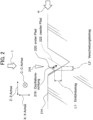
2 ist eine erklärende Ansicht, die ein Beispiel für eine Bewegung mit einem anderen Bearbeitungsverfahren (Flankenzuführung) als der radialen Zuführung gemäß der Ausführungsform zeigt;2 Fig. 10 is an explanatory view showing an example of movement with a machining method (flank feeding) other than the radial feeding according to the embodiment; -
3 ist eine andere erklärende Ansicht, die ein Beispiel für eine Bewegung mit dem Bearbeitungsverfahren (Flankenzuführung) zeigt, das sich von der radialen Zuführung gemäß der Ausführungsform unterscheidet;3 Fig. 12 is another explanatory view showing an example of movement with the machining method (flank feeding) different from the radial feeding according to the embodiment; -
4 zeigt das Erscheinungsbild einer durch Gewindeschneiden gebildeten Schraube;4 shows the appearance of a screw formed by thread cutting; -
5 ist eine erklärende Ansicht, die zeigt, wie das Gewindeschneiden zum Formen der Schraube durchgeführt wird;5 is an explanatory view showing how thread cutting is performed to form the screw; -
6 ist eine vergrößerte Ansicht eines Bereichs A von5 und ist eine erklärende Ansicht, die das Gewindeschneiden mit Oszillation in einer X-Achsenrichtung zeigt, nämlich relative Oszillation zwischen einem Werkstück und einem Schneidwerkzeug und Oszillation in einer radialen Richtung des Werkstücks;6 is an enlarged view of an area A of5 and is an explanatory view showing thread cutting with oscillation in an X-axis direction, namely, relative oscillation between a workpiece and a cutting tool and oscillation in a radial direction of the workpiece; -
7 ist eine Ansicht aus einem Pfeil D von6 und ist eine erklärende Ansicht, die das Gewindeschneiden mit Oszillation in radialer Richtung des Werkstücks zeigt;7 is a view from an arrow D of6 and is an explanatory view showing tapping with oscillation in the radial direction of the workpiece; -
8 ist eine Ansicht aus einem Pfeil E von7 und ist eine erklärende Ansicht, die das Gewindeschneiden mit Oszillation in radialer Richtung des Werkstücks zeigt;8th is a view from an arrow E of7 and is an explanatory view showing tapping with oscillation in the radial direction of the workpiece; -
9 ist eine vergrößerte Ansicht des Bereichs A von5 und ist eine erklärende Ansicht, die die Bewegung beim Gewindeschneiden mit Oszillation in radialer Richtung des Werkstücks zeigt, auf das die Flankenzuführung angewendet wird;9 is an enlarged view of area A of5 and is an explanatory view showing the movement in tapping with oscillation in the radial direction of the workpiece to which the flank feeding is applied; -
10 ist eine erklärende Ansicht, die die Bewegung beim Gewindeschneiden aus einem Pfeil F von9 zeigt, der eine Oszillation in radialer Richtung des Werkstücks umfasst, auf das die Flankenzuführung angewendet wird; und10 is an explanatory view showing the movement in thread cutting from an arrow F of9 10, which includes oscillation in the radial direction of the workpiece to which the flank feeding is applied; and -
11 ist eine Ansicht aus einem Pfeil G der10 und ist eine erklärende Ansicht, die eine Bewegung beim Gewindeschneiden mit Oszillation in radialer Richtung des Werkstücks zeigt, auf das die Flankenzuführung angewendet wird.11 is a view from an arrow G of10 and is an explanatory view showing a movement in tapping with oscillation in the radial direction of the workpiece to which the flank feeding is applied.
AUSFÜHRLICHE BESCHREIBUNG DER ERFINDUNGDETAILED DESCRIPTION OF THE INVENTION
Eine Ausführungsform der vorliegenden Erfindung wird im Folgenden anhand der Zeichnungen ausführlich beschrieben.An embodiment of the present invention is described in detail below with reference to the drawings.
Wie in
Die Oszillationsbedingungsberechnungseinheit 102 empfängt ein Bearbeitungsprogramm von außen und berechnet aus dem Bearbeitungsprogramm wenigstens die Oszillationsamplitude und die Richtung der Oszillation. In der Ausführungsform vergleicht die Oszillationsbedingungsberechnungseinheit 102 einen aktuellen Bearbeitungspfad und einen letzten Bearbeitungspfad basierend auf dem Inhalt des eingegebenen Bearbeitungsprogramms und bestimmt einen Einführbetrag in radialer Richtung eines Werkstücks (X-Achsenrichtung) relativ zum letzten Bearbeitungspfad und einen Verschiebungsbetrag in Umfangsrichtung des Werkstücks (Z-Achsenrichtung) relativ zum letzten Bearbeitungspfad. Basierend auf dem ermittelten Einführbetrag und dem Verschiebungsbetrag berechnet die Oszillationsbedingungsberechnungseinheit 102 die Oszillationsamplitude und die Richtung der Oszillation, um das Zerkleinern von Spänen während der Dreh- und Fräsbearbeitung zu ermöglichen.The oscillation
Insbesondere berechnet die Oszillationsbedingungsberechnungseinheit 102 basierend auf dem Einführbetrag in radialer Richtung des Werkstücks (X-Achsenrichtung) relativ zum letzten Bearbeitungspfad und dem Verschiebungsbetrag in Umfangsrichtung des Werkstücks (Z-Achsenrichtung) relativ zum letzten Bearbeitungspfad eine Oszillationsamplitude und eine Oszillationsrichtung, um ein Teil aufzunehmen, das teilweise bereits durch Dreh- und Fräsbearbeitung entlang des letzten Bearbeitungspfads bearbeitet wurde.Specifically, the oscillation
In der Ausführungsform werden durch die Bereitstellung der vorgenannten Oszillationsbedingungsberechnungseinheit 102 Bearbeitungsbahnen verglichen, um die Oszillationsamplitude und die Richtung der Oszillation zu berechnen. Dadurch ist es möglich, Späne, die durch die Dreh- und Fräsbearbeitung entstehen, zuverlässig zu zerkleinern. Dadurch wird es möglich, die Oszillation, die auf verschiedene Arten von Bearbeitungsverfahren anspricht, flexibel im Vergleich zur herkömmlichen Technik anzuwenden, bei der die Oszillation einfach nur in X-Achsrichtung (radiale Richtung eines Werkstücks) gesteuert wird.In the embodiment, by providing the aforementioned oscillation
Das Bearbeitungsprogramm ist ein Programm, das die Bewegung bei der Dreh- und Fräsbearbeitung auf einem Werkstück 214 beschreibt. Die Überprüfung des Bearbeitungsprogramms ermöglicht es somit, die relativen Positionen der Bearbeitungsbahnen während der Bearbeitung durch Schneiden zu sehen. Dadurch kann die Oszillationsbedingungsberechnungseinheit 102 den aktuellen Bearbeitungspfad und den letzten Bearbeitungspfad vergleichen und den Einführbetrag in radialer Richtung des Werkstücks (X-Achsrichtung) und den Verschiebungsbetrag in Umfangsrichtung des Werkstücks (Z-Achsrichtung) sehen, wie vorstehend beschrieben. Das Bearbeitungsprogramm kann der Oszillationsbedingungsberechnungseinheit 102 über verschiedene Schnittstellen zur Verfügung gestellt werden. In der Abbildung von
Die Oszillationsbedingungsberechnungseinheit 102 kann mit einem Programm, das die vorgenannte Bewegung beschreibt, einer CPU zur Ausführung des Programms und einer Eingabeschnittstelle zur Eingabe des Bearbeitungsprogramms konfiguriert sein. Wie vorstehend beschrieben, ist die Bereitstellung dieser Eingangsschnittstelle nicht immer erforderlich, wenn das Bearbeitungsprogramm in der Steuerung 100 gespeichert ist.The oscillation
Die Oszillationsbefehlsberechnungseinheit 104 berechnet einen Oszillationsbefehl, der einem Bewegungsbefehl für jede Achse überlagert werden soll, beispielsweise zum Gewindeschneiden des Werkstücks 214. Ausgehend von der Oszillationsamplitude und der von der Oszillationsbedingungsberechnungseinheit 102 berechneten Richtung der Oszillation berechnet die Oszillationsbefehlsberechnungseinheit 104 einen Oszillationsbefehl zur Steuerung dieser Oszillation.The oscillation
In Bezug auf eine Oszillationsfrequenz (oder Zyklus) kann die Oszillationsbefehlsberechnungseinheit 104 einen Oszillationsbefehl für diesen Oszillationsfrequenzeingang von außen berechnen (nicht dargestellt). Alternativ kann diese Oszillationsfrequenz vorab in der Oszillationsbefehlsberechnungseinheit 104 gespeichert werden. So kann beispielsweise die Oszillationsfrequenz (oder Zyklus) ein Produkt aus der Drehzahl einer Spindelachse multipliziert mit einer Konstanten sein. Die Oszillation kann beispielsweise in Form einer Sinuswelle erfolgen. Für ein zyklisches Signal ist unterdessen beispielsweise ein Dreieckssignal anwendbar. Diese Oszillationsbedingungen können über eine vorgegebene Eingangsschnittstelle eingegeben werden. So kann beispielsweise ein Bediener die Oszillationsbedingungen über eine Tastatur oder eine Maus eingeben. Alternativ können die Oszillationsbedingungen von einem anderen Computer über eine vorgegebene Kommunikationsschnittstelle eingegeben werden.With respect to an oscillation frequency (or cycle), the oscillation
Die Oszillationsbefehlsberechnungseinheit 104 kann auch mit einem Programm konfiguriert sein, das die Bewegung durch die Oszillationsbefehlsberechnungseinheit 104 beschreibt, und mit einer CPU zur Ausführung des Programms. Die Oszillationsbefehlsberechnungseinheit 104 kann eine vorbestimmte Schnittstelle zur Eingabe einer Oszillationsbedingung umfassen.The oscillation
Der erste Addierer 106 empfängt den von der vorgenannten übergeordneten Steuerung gelieferten Bewegungsbefehl. Dieser Bewegungsbefehl ist ein Bewegungsbefehl, der auf die Vorrichtung (Steuerung 100) verteilt wird, zu der der erste Addierer 106 gehört. Der erste Addierer 106 subtrahiert von diesem Bewegungsbefehl einen vom Motor 120 der Werkzeugmaschine übertragenen Positionsrückmeldewert und gibt ein aus der Subtraktion resultierendes Bewegungssignal aus. Dadurch wird es möglich, eine so genannte Rückkopplungskontrolle durchzuführen. Der erste Addierer 106 kann auch mit einem Programm konfiguriert sein, das die Bewegung des ersten Addierers 106 beschreibt, und einer CPU, um das Programm auszuführen.The
Der zweite Addierer 110 addiert ein Ergebnis der Berechnung durch den ersten Addierer 106 und den Oszillationsbefehl und gibt ein Endbewegungssignal aus. Auf diese Weise kann dem Bewegungsbefehl eine Oszillation zugeführt werden. Der zweite Addierer 110 kann auch mit einem Programm konfiguriert sein, das die Bewegung des zweiten Addierers 110 beschreibt, und einer CPU zur Ausführung des Programms.The
Die Steuereinheit 112 empfängt den Bewegungsbefehl einschließlich des Oszillationsbefehls, der durch den zweiten Addierer 110 hinzugefügt wird. Anschließend berechnet die Steuereinheit 112 einen Antriebsbefehl zum Antreiben des Motors 120 als Reaktion auf eine Position und Abweichung des aus der Addition resultierenden Bewegungsbefehls. Die Steuereinheit 112 kann auch mit einem Programm konfiguriert sein, das die Bewegung der Steuereinheit 112 beschreibt, und mit einer CPU zur Ausführung des Programms. Dieser Antriebsbefehl wird dem Motor 120 der Werkzeugmaschine zugeführt und ist eine Befehlsausgabe an den Motor 120 zum Antreiben jeder Achse der Werkzeugmaschine.The
Eine der Eigenschaften der Steuerung 100 der Ausführungsform ist, dass zum Zerkleinern von Spänen, die beim Gewindeschneiden auftreten, das Werkstück 214 und ein Schneidwerkzeug 216 nach einem Gewindeschneidverfahren gegeneinander oszillieren. Diese relative Oszillation kann eine Bewegung des Schneidwerkzeugs 216 sein, während das Werkstück 214 stoppt, oder eine Bewegung des Werkstücks 214, während das Schneidwerkzeug 216 stoppt. Alternativ können sich das Werkstück 214 und das Schneidwerkzeug 216 gleichzeitig bewegen. In einem im Folgenden hauptsächlich beschriebenen Fall wird das Schneidwerkzeug 216 mit einer Oszillation beaufschlagt. Alternativ kann das Werkstück 214 zum Schwingen konfiguriert sein. Nach der herkömmlichen Technik wird die Oszillation nur in radialer Richtung des Werkstücks 214 angewendet. Im Gegensatz dazu werden in der Ausführungsform die Amplitude und die Oszillationsrichtung als Reaktion auf eine Bearbeitungsrichtung gesteuert, um eine zuverlässigere Zerkleinerung von Spänen zu ermöglichen.One of the features of the
Bei diesem Bearbeitungsverfahren (Flankenzuführung) bewegt sich das Schneidwerkzeug 216 nach der Durchführung der Bearbeitung durch Schneiden entlang einer ersten Bahn so, dass eine Gleitbewegung einer Oberfläche einer Werkzeugspitze des Schneidwerkzeugs 216 erfolgt (das Werkstück 214 wird nicht mit dem beweglichen Schneidwerkzeug 216 geschnitten). Genauer gesagt, wird das Schneidwerkzeug 216 in eine tiefere Position gebracht, während es in Richtung Z-Achse verschoben wird. Nachdem sich das Schneidwerkzeug 216 in der tieferen Position befindet, wird das Schneidwerkzeug 216 zur Bearbeitung durch Schneiden entlang einer zweiten Bahn verwendet (siehe
Die Ausführungsform ist dadurch gekennzeichnet, dass die Oszillationsamplitude und die Richtung der Oszillation basierend auf einem Werkzeugpfad 220 auf einem ersten Pfad und einem Werkzeugpfad 222 auf dem zweiten Pfad bestimmt werden. Nach der herkömmlichen Technik (siehe
Gemäß dem in
In diesem Zusammenhang berechnet die Oszillationsbedingungsberechnungseinheit 102 der Ausführungsform die Oszillationsamplitude und die Richtung der Oszillation basierend auf dem vorgenannten Einführbetrag L1 und dem Verschiebungsbetrag L2. So wird beispielsweise ein Abstand zwischen dem Werkzeugpfad 220 auf dem ersten Pfad und dem Werkzeugpfad 222 auf dem zweiten Pfad basierend auf dem Einführbetrag L1 und dem Verschiebungsbetrag L2 bestimmt. Somit kann die Amplitude der Oszillation proportional zum bestimmten Abstand berechnet werden. Weiterhin wird die Richtung dem Werkzeugpfad 222 auf dem zweiten Pfad, betrachtet von dem Werkzeugpfad 220 auf dem ersten Pfad, basierend auf dem Einführbetrag L1 und dem Verschiebungsbetrag L2 bestimmt. Somit kann die Richtung der Oszillation so berechnet werden, dass sie der bestimmten Richtung entspricht. Die Oszillationsbedingungsberechnungseinheit 102 kann die Oszillationsamplitude und die Richtung der bei der Bearbeitung anzuwendenden Oszillation berechnen, indem sie beispielsweise auf dem zweiten Pfad schneidet, indem sie diesen Prozessen folgt. Dadurch kann, wie in
Eine Ansicht aus einem Pfeil H von
In
Gemäß der Ausführungsform bestimmt die Oszillationsbedingungsberechnungseinheit 102 einen Einführbetrag in X-Achsenrichtung und einen Verschiebungsbetrag entlang der Z-Achse relativ zu einem letzten Bearbeitungspfad (ein Werkzeugpfad auf einem ersten Pfad) basierend auf dem letzten Bearbeitungspfad und einem aktuellen Bearbeitungspfad (ein Werkzeugpfad auf einem zweiten Pfad). Basierend auf dem ermittelten Einführbetrag und dem Verschiebungsbetrag berechnet die Oszillationsbedingungsberechnungseinheit 102 die Oszillationsamplitude und die Richtung der Oszillation. So kann auch bei verschiedenen Arten von Bearbeitungsverfahren ein Leerlaufbereich auf einer Bearbeitungsbahn zuverlässig bereitgestellt werden, um eine zuverlässige Zerkleinerung von Spänen zu ermöglichen. Mit anderen Worten, die Steuerung 100, die in der Lage ist, Späne in jedem beliebigen Gewindeschneidverfahren zu zerkleinern, kann realisiert werden. Dadurch wird es je nach Ausführungsform möglich, Späne in allen Gewindeschneidverfahren zu zerkleinern, einschließlich radialer Zuführung (rechtwinklige Zuführung), Flankenzuführung (einseitige Zuführung), alternierender Zuführung (versetzte Zuführung) usw.According to the embodiment, the oscillation
Während die Ausführungsform der vorliegenden Erfindung bereits ausführlich beschrieben wurde, zeigt die vorstehende Ausführungsform lediglich konkrete Beispiele für die Umsetzung der vorliegenden Erfindung. Der technische Umfang der vorliegenden Erfindung beschränkt sich nicht auf die vorgenannte Ausführungsform. Für die vorliegende Erfindung gelten verschiedene Änderungen in einem Bereich, der nicht vom Inhalt der Erfindung abweicht. Alle diese Änderungen sind auch im technischen Umfang der vorliegenden Erfindung enthalten.While the embodiment of the present invention has already been described in detail, the above embodiment merely shows concrete examples of the implementation of the present invention. The technical scope of the present invention is not limited to the aforementioned embodiment. Various changes apply to the present invention in a scope that does not depart from the spirit of the invention. All of these changes are also included within the technical scope of the present invention.
In dem in der vorstehenden Ausführungsform beschriebenen Beispiel wird ein Oszillationsbefehl auf einen Bewegungsbefehl für das Schneidwerkzeug 216 angewendet. Die Ausführungsform umfasst jedoch auch einen Fall, in dem ein Oszillationsbefehl auf das Werkstück 214 angewendet wird. Ein Oszillationsbefehl kann auch auf eine andere Achse angewendet werden. In dem in der vorstehenden Ausführungsform beschriebenen Beispiel wird eine V-förmige Klinge als Schneidwerkzeug 216 verwendet. Es ist aber auch ein Schneidwerkzeug mit einer anderen Form einsetzbar.In the example described in the above embodiment, an oscillation command is applied to a movement command for the
In dem in der vorstehenden Ausführungsform beschriebenen Beispiel umfasst die spanende Bearbeitung eine Oszillation, die beim Gewindeschneiden angewendet wird. Die Bearbeitung durch Schneiden ohne Oszillation kann jedoch als Endprozess durchgeführt werden. Der Schlichtvorgang kann ohne Oszillation durchgeführt werden, um die Bearbeitungsgenauigkeit zu erhöhen. Dies kann erreicht werden, indem die Oszillationsbefehlsberechnungseinheit 104 so konfiguriert wird, dass die Oszillationsbefehlsberechnungseinheit 104 keinen Oszillationsbefehl für die Endbearbeitung durch spanende Bearbeitung ausgibt. Alternativ kann die Oszillationsbefehlsberechnungseinheit 104 konfiguriert sein, um einen Oszillationsbefehl mit einem Wert 0 für die Endbearbeitung durch Zerspanung auszugeben. Hier bedeutet ein Wert von 0, dass er keine Oszillationen verursacht.In the example described in the above embodiment, the machining includes oscillation applied to thread cutting. However, machining by cutting without oscillation can be performed as a final process. The finishing process can be carried out without oscillation to increase the machining accuracy. This can be achieved by configuring the oscillation
ERLÄUTERUNG DER BEZUGSZEICHENEXPLANATION OF REFERENCE SYMBOLS
- 10, 10a10, 10a
- Gewindenutthread groove
- 1212
- Schraubescrew
- 14, 21414, 214
- Werkstückworkpiece
- 16, 21616, 216
- Schneidwerkzeugcutting tool
- 1818
- SpindelachseSpindle axis
- 1919
- OszillationsrichtungOscillation direction
- 20, 22020, 220
- Werkzeugpfad auf erstem PfadToolpath on first path
- 22, 22222, 222
- Werkzeugpfad auf zweitem PfadTool path on second path
- 100100
- Steuerungsteering
- 102102
- OszillationsbedingungsberechnungseinheitOscillation condition calculation unit
- 104104
- OszillationsbefehlsberechnungseinheitOscillation command calculation unit
- 106106
- Erster AddiererFirst adder
- 110110
- Zweiter AddiererSecond adder
- 112112
- SteuereinheitControl unit
- 120120
- Motorengine
- 224a224a
- Bearbeitungspfad auf erstem PfadEdit path on first path
- 224b224b
- Bearbeitungsbahn auf zweitem PfadMachining path on second path
- C,C,
- C-AchseC axis
- J, J2J, J2
- Leerlaufidle
- J1J1
- Bereich, in dem kein Leerlauf erzeugt werden kannArea in which no idle can be generated
- K1, K2K1, K2
- KlingenbreiteBlade width
- L1L1
- EinführbetragIntroduction amount
- L2L2
- VerschiebungsbetragShift amount
- XX
- X-AchseX axis
- ZZ
- Z-AchseZ axis
Claims (3)
Applications Claiming Priority (2)
| Application Number | Priority Date | Filing Date | Title |
|---|---|---|---|
| JP2018074955A JP6784717B2 (en) | 2018-04-09 | 2018-04-09 | Machine tool control device |
| JP2018-074955 | 2018-04-09 |
Publications (2)
| Publication Number | Publication Date |
|---|---|
| DE102019205035A1 DE102019205035A1 (en) | 2019-10-10 |
| DE102019205035B4 true DE102019205035B4 (en) | 2024-01-18 |
Family
ID=67992050
Family Applications (1)
| Application Number | Title | Priority Date | Filing Date |
|---|---|---|---|
| DE102019205035.2A Active DE102019205035B4 (en) | 2018-04-09 | 2019-04-09 | Control for machine tools |
Country Status (4)
| Country | Link |
|---|---|
| US (1) | US10802461B2 (en) |
| JP (1) | JP6784717B2 (en) |
| CN (1) | CN110362033B (en) |
| DE (1) | DE102019205035B4 (en) |
Families Citing this family (10)
| Publication number | Priority date | Publication date | Assignee | Title |
|---|---|---|---|---|
| JP7497968B2 (en) * | 2019-10-01 | 2024-06-11 | ファナック株式会社 | Numerical control device, machine tool system, and numerical control method |
| CN110899738B (en) * | 2019-11-28 | 2020-09-08 | 浙江陀曼精密机械有限公司 | Feed amount adjusting method for lathe |
| EP3892405A1 (en) * | 2020-04-08 | 2021-10-13 | AB Sandvik Coromant | A method for cutting metallic threads |
| US12405591B2 (en) * | 2020-05-21 | 2025-09-02 | Fanuc Corporation | Numerical control device and control method |
| WO2021241552A1 (en) * | 2020-05-29 | 2021-12-02 | ファナック株式会社 | Machine tool control device |
| JP7509881B2 (en) * | 2020-07-10 | 2024-07-02 | ファナック株式会社 | Machine tool control device |
| US12326713B2 (en) | 2021-03-26 | 2025-06-10 | Fanuc Corporation | Servo control device |
| US20240061389A1 (en) | 2021-03-26 | 2024-02-22 | Fanuc Corporation | Servo control device |
| US20240131648A1 (en) * | 2021-06-22 | 2024-04-25 | Fanuc Corporation | Machine tool control device |
| WO2024116341A1 (en) * | 2022-11-30 | 2024-06-06 | ファナック株式会社 | Machine tool control device |
Citations (3)
| Publication number | Priority date | Publication date | Assignee | Title |
|---|---|---|---|---|
| DE102015001509A1 (en) | 2014-02-12 | 2015-08-13 | Fanuc Corporation | Numerical control |
| JP5851670B1 (en) | 2014-10-28 | 2016-02-03 | 三菱電機株式会社 | Numerical controller |
| WO2016056526A1 (en) | 2014-10-08 | 2016-04-14 | シチズンホールディングス株式会社 | Machine tool and control device for machine tool |
Family Cites Families (16)
| Publication number | Priority date | Publication date | Assignee | Title |
|---|---|---|---|---|
| JPS5851670A (en) | 1981-09-22 | 1983-03-26 | Nec Corp | Automatic gain controlling system |
| EP0197172B1 (en) * | 1985-04-09 | 1988-07-27 | Wilhelm Hegenscheidt Gesellschaft mbH | Device to obtain broken chips during the machining of work pieces |
| JP2587538B2 (en) * | 1990-11-30 | 1997-03-05 | 日本ニューマチック工業株式会社 | Vibration cutting equipment |
| JP4819665B2 (en) * | 2006-12-18 | 2011-11-24 | オークマ株式会社 | Non-circular shape processing equipment |
| US8240234B2 (en) * | 2007-10-16 | 2012-08-14 | University Of North Carolina At Charlotte | Methods and systems for chip breaking in turning applications using CNC toolpaths |
| SE533786C2 (en) * | 2009-05-25 | 2011-01-11 | Sandvik Intellectual Property | Apparatus and method for milling material |
| DE102013110728B4 (en) * | 2013-09-27 | 2021-08-19 | Ev Group E. Thallner Gmbh | System and method for machining a workpiece |
| JP5606658B1 (en) * | 2014-03-17 | 2014-10-15 | 三菱電機株式会社 | Numerical controller |
| US10268176B2 (en) * | 2014-03-26 | 2019-04-23 | Citizen Watch Co., Ltd. | Control device for machine tool and machine tool including the control device |
| CN106255571B (en) * | 2014-03-26 | 2018-11-23 | 西铁城时计株式会社 | The control device of lathe and the lathe for having the control device |
| US9886022B2 (en) * | 2014-04-23 | 2018-02-06 | Mitsubishi Electric Corporation | Numerical control device |
| DE112014007112B4 (en) * | 2014-10-28 | 2021-12-30 | Mitsubishi Electric Corporation | Numerically controlled device |
| TWI568528B (en) * | 2014-11-06 | 2017-02-01 | 財團法人工業技術研究院 | Cutting tool controller and controlling method thereof |
| JP6342935B2 (en) * | 2016-03-29 | 2018-06-13 | ファナック株式会社 | Servo control device, control method and computer program for machine tool for rocking cutting |
| JP6487397B2 (en) * | 2016-09-07 | 2019-03-20 | ファナック株式会社 | Machine tool control device, control method, and computer program |
| JP6885910B2 (en) * | 2018-10-15 | 2021-06-16 | ファナック株式会社 | Numerical control device |
-
2018
- 2018-04-09 JP JP2018074955A patent/JP6784717B2/en active Active
-
2019
- 2019-04-04 CN CN201910270923.1A patent/CN110362033B/en active Active
- 2019-04-08 US US16/377,670 patent/US10802461B2/en active Active
- 2019-04-09 DE DE102019205035.2A patent/DE102019205035B4/en active Active
Patent Citations (3)
| Publication number | Priority date | Publication date | Assignee | Title |
|---|---|---|---|---|
| DE102015001509A1 (en) | 2014-02-12 | 2015-08-13 | Fanuc Corporation | Numerical control |
| WO2016056526A1 (en) | 2014-10-08 | 2016-04-14 | シチズンホールディングス株式会社 | Machine tool and control device for machine tool |
| JP5851670B1 (en) | 2014-10-28 | 2016-02-03 | 三菱電機株式会社 | Numerical controller |
Also Published As
| Publication number | Publication date |
|---|---|
| CN110362033A (en) | 2019-10-22 |
| JP2019185355A (en) | 2019-10-24 |
| US10802461B2 (en) | 2020-10-13 |
| CN110362033B (en) | 2024-03-08 |
| JP6784717B2 (en) | 2020-11-11 |
| US20190310601A1 (en) | 2019-10-10 |
| DE102019205035A1 (en) | 2019-10-10 |
Similar Documents
| Publication | Publication Date | Title |
|---|---|---|
| DE102019205035B4 (en) | Control for machine tools | |
| DE102020123441B4 (en) | Control device for a machine tool | |
| DE102017208060B4 (en) | SERVO CONTROL, CONTROL METHOD, AND COMPUTER PROGRAM FOR A MACHINE TOOL FOR OSCILLATION CUTTING | |
| DE102018005754B4 (en) | CONTROL DEVICE FOR A MACHINE TOOL FOR PERFORMING VIBRATION CUTTING | |
| DE102018218201B4 (en) | NUMERICAL CONTROL DEVICE, CNC MACHINE TOOL, NUMERICAL CONTROL METHOD AND PROGRAM FOR A NUMERICAL CONTROL DEVICE | |
| DE112014007112B4 (en) | Numerically controlled device | |
| DE102018218202B4 (en) | Postprocessor device, machine program generation method, CNC machining system and program for machine program generation | |
| DE112019007578B4 (en) | Numerical control, numerical control method and machine learning device | |
| DE102020203935B4 (en) | Servo control device | |
| DE102019204862A1 (en) | CONTROL FOR A TOOL MACHINE | |
| DE102019204643A1 (en) | CONTROL DEVICE FOR A TOOL MACHINE | |
| DE102015111964B4 (en) | Servo motor control system that improves the machining precision of multiple axes | |
| DE102016003049B4 (en) | Numerical control for performing reciprocal rotation in a complex fixed cycle | |
| DE102020203934B4 (en) | Servo control device | |
| EP3396481A1 (en) | Method for compensating for the push of a milling cutter | |
| DE102018002308B4 (en) | Numerical control | |
| DE102020132660A1 (en) | Control device for machine tools and machine tool control methods | |
| EP1592527B1 (en) | Method and device for milling freeform surfaces | |
| DE112021007507T5 (en) | Information processing device, device for controlling machine tools and computer program | |
| DE102020202700A1 (en) | CONTROL DEVICE FOR MACHINE TOOLS | |
| DE10322340A1 (en) | Method and device for milling free-form surfaces | |
| DE112013006637B4 (en) | Numerical control device and machining process | |
| DE112021007567T5 (en) | Machine tool control device | |
| DE102019215626B4 (en) | Numerical control device | |
| DE102018004678B4 (en) | Numerical control with a tool retraction function |
Legal Events
| Date | Code | Title | Description |
|---|---|---|---|
| R012 | Request for examination validly filed | ||
| R016 | Response to examination communication | ||
| R018 | Grant decision by examination section/examining division | ||
| R020 | Patent grant now final |