DE102016117885A1 - Method for producing a decoupling element for an optoelectronic component and decoupling element - Google Patents
Method for producing a decoupling element for an optoelectronic component and decoupling element Download PDFInfo
- Publication number
- DE102016117885A1 DE102016117885A1 DE102016117885.3A DE102016117885A DE102016117885A1 DE 102016117885 A1 DE102016117885 A1 DE 102016117885A1 DE 102016117885 A DE102016117885 A DE 102016117885A DE 102016117885 A1 DE102016117885 A1 DE 102016117885A1
- Authority
- DE
- Germany
- Prior art keywords
- quantum dots
- ligand shell
- phosphonate
- matrix material
- decoupling element
- Prior art date
- Legal status (The legal status is an assumption and is not a legal conclusion. Google has not performed a legal analysis and makes no representation as to the accuracy of the status listed.)
- Pending
Links
Images


Classifications
-
- H—ELECTRICITY
- H10—SEMICONDUCTOR DEVICES; ELECTRIC SOLID-STATE DEVICES NOT OTHERWISE PROVIDED FOR
- H10H—INORGANIC LIGHT-EMITTING SEMICONDUCTOR DEVICES HAVING POTENTIAL BARRIERS
- H10H20/00—Individual inorganic light-emitting semiconductor devices having potential barriers, e.g. light-emitting diodes [LED]
- H10H20/80—Constructional details
- H10H20/85—Packages
- H10H20/851—Wavelength conversion means
- H10H20/8511—Wavelength conversion means characterised by their material, e.g. binder
- H10H20/8512—Wavelength conversion materials
-
- C—CHEMISTRY; METALLURGY
- C08—ORGANIC MACROMOLECULAR COMPOUNDS; THEIR PREPARATION OR CHEMICAL WORKING-UP; COMPOSITIONS BASED THEREON
- C08L—COMPOSITIONS OF MACROMOLECULAR COMPOUNDS
- C08L83/00—Compositions of macromolecular compounds obtained by reactions forming in the main chain of the macromolecule a linkage containing silicon with or without sulfur, nitrogen, oxygen or carbon only; Compositions of derivatives of such polymers
- C08L83/04—Polysiloxanes
-
- C—CHEMISTRY; METALLURGY
- C09—DYES; PAINTS; POLISHES; NATURAL RESINS; ADHESIVES; COMPOSITIONS NOT OTHERWISE PROVIDED FOR; APPLICATIONS OF MATERIALS NOT OTHERWISE PROVIDED FOR
- C09K—MATERIALS FOR MISCELLANEOUS APPLICATIONS, NOT PROVIDED FOR ELSEWHERE
- C09K11/00—Luminescent materials, e.g. electroluminescent or chemiluminescent
- C09K11/02—Use of particular materials as binders, particle coatings or suspension media therefor
- C09K11/025—Use of particular materials as binders, particle coatings or suspension media therefor non-luminescent particle coatings or suspension media
-
- C—CHEMISTRY; METALLURGY
- C09—DYES; PAINTS; POLISHES; NATURAL RESINS; ADHESIVES; COMPOSITIONS NOT OTHERWISE PROVIDED FOR; APPLICATIONS OF MATERIALS NOT OTHERWISE PROVIDED FOR
- C09K—MATERIALS FOR MISCELLANEOUS APPLICATIONS, NOT PROVIDED FOR ELSEWHERE
- C09K11/00—Luminescent materials, e.g. electroluminescent or chemiluminescent
- C09K11/08—Luminescent materials, e.g. electroluminescent or chemiluminescent containing inorganic luminescent materials
- C09K11/62—Luminescent materials, e.g. electroluminescent or chemiluminescent containing inorganic luminescent materials containing gallium, indium or thallium
-
- C—CHEMISTRY; METALLURGY
- C09—DYES; PAINTS; POLISHES; NATURAL RESINS; ADHESIVES; COMPOSITIONS NOT OTHERWISE PROVIDED FOR; APPLICATIONS OF MATERIALS NOT OTHERWISE PROVIDED FOR
- C09K—MATERIALS FOR MISCELLANEOUS APPLICATIONS, NOT PROVIDED FOR ELSEWHERE
- C09K11/00—Luminescent materials, e.g. electroluminescent or chemiluminescent
- C09K11/08—Luminescent materials, e.g. electroluminescent or chemiluminescent containing inorganic luminescent materials
- C09K11/70—Luminescent materials, e.g. electroluminescent or chemiluminescent containing inorganic luminescent materials containing phosphorus
-
- B—PERFORMING OPERATIONS; TRANSPORTING
- B82—NANOTECHNOLOGY
- B82Y—SPECIFIC USES OR APPLICATIONS OF NANOSTRUCTURES; MEASUREMENT OR ANALYSIS OF NANOSTRUCTURES; MANUFACTURE OR TREATMENT OF NANOSTRUCTURES
- B82Y20/00—Nanooptics, e.g. quantum optics or photonic crystals
-
- C—CHEMISTRY; METALLURGY
- C08—ORGANIC MACROMOLECULAR COMPOUNDS; THEIR PREPARATION OR CHEMICAL WORKING-UP; COMPOSITIONS BASED THEREON
- C08G—MACROMOLECULAR COMPOUNDS OBTAINED OTHERWISE THAN BY REACTIONS ONLY INVOLVING UNSATURATED CARBON-TO-CARBON BONDS
- C08G77/00—Macromolecular compounds obtained by reactions forming a linkage containing silicon with or without sulfur, nitrogen, oxygen or carbon in the main chain of the macromolecule
- C08G77/80—Siloxanes having aromatic substituents, e.g. phenyl side groups
-
- H—ELECTRICITY
- H10—SEMICONDUCTOR DEVICES; ELECTRIC SOLID-STATE DEVICES NOT OTHERWISE PROVIDED FOR
- H10H—INORGANIC LIGHT-EMITTING SEMICONDUCTOR DEVICES HAVING POTENTIAL BARRIERS
- H10H20/00—Individual inorganic light-emitting semiconductor devices having potential barriers, e.g. light-emitting diodes [LED]
- H10H20/01—Manufacture or treatment
- H10H20/036—Manufacture or treatment of packages
- H10H20/0361—Manufacture or treatment of packages of wavelength conversion means
-
- H—ELECTRICITY
- H10—SEMICONDUCTOR DEVICES; ELECTRIC SOLID-STATE DEVICES NOT OTHERWISE PROVIDED FOR
- H10H—INORGANIC LIGHT-EMITTING SEMICONDUCTOR DEVICES HAVING POTENTIAL BARRIERS
- H10H20/00—Individual inorganic light-emitting semiconductor devices having potential barriers, e.g. light-emitting diodes [LED]
- H10H20/01—Manufacture or treatment
- H10H20/036—Manufacture or treatment of packages
- H10H20/0362—Manufacture or treatment of packages of encapsulations
-
- Y—GENERAL TAGGING OF NEW TECHNOLOGICAL DEVELOPMENTS; GENERAL TAGGING OF CROSS-SECTIONAL TECHNOLOGIES SPANNING OVER SEVERAL SECTIONS OF THE IPC; TECHNICAL SUBJECTS COVERED BY FORMER USPC CROSS-REFERENCE ART COLLECTIONS [XRACs] AND DIGESTS
- Y10—TECHNICAL SUBJECTS COVERED BY FORMER USPC
- Y10S—TECHNICAL SUBJECTS COVERED BY FORMER USPC CROSS-REFERENCE ART COLLECTIONS [XRACs] AND DIGESTS
- Y10S438/00—Semiconductor device manufacturing: process
- Y10S438/962—Quantum dots and lines
-
- Y—GENERAL TAGGING OF NEW TECHNOLOGICAL DEVELOPMENTS; GENERAL TAGGING OF CROSS-SECTIONAL TECHNOLOGIES SPANNING OVER SEVERAL SECTIONS OF THE IPC; TECHNICAL SUBJECTS COVERED BY FORMER USPC CROSS-REFERENCE ART COLLECTIONS [XRACs] AND DIGESTS
- Y10—TECHNICAL SUBJECTS COVERED BY FORMER USPC
- Y10S—TECHNICAL SUBJECTS COVERED BY FORMER USPC CROSS-REFERENCE ART COLLECTIONS [XRACs] AND DIGESTS
- Y10S977/00—Nanotechnology
- Y10S977/70—Nanostructure
- Y10S977/773—Nanoparticle, i.e. structure having three dimensions of 100 nm or less
- Y10S977/774—Exhibiting three-dimensional carrier confinement, e.g. quantum dots
-
- Y—GENERAL TAGGING OF NEW TECHNOLOGICAL DEVELOPMENTS; GENERAL TAGGING OF CROSS-SECTIONAL TECHNOLOGIES SPANNING OVER SEVERAL SECTIONS OF THE IPC; TECHNICAL SUBJECTS COVERED BY FORMER USPC CROSS-REFERENCE ART COLLECTIONS [XRACs] AND DIGESTS
- Y10—TECHNICAL SUBJECTS COVERED BY FORMER USPC
- Y10S—TECHNICAL SUBJECTS COVERED BY FORMER USPC CROSS-REFERENCE ART COLLECTIONS [XRACs] AND DIGESTS
- Y10S977/00—Nanotechnology
- Y10S977/70—Nanostructure
- Y10S977/778—Nanostructure within specified host or matrix material, e.g. nanocomposite films
Landscapes
- Chemical & Material Sciences (AREA)
- Organic Chemistry (AREA)
- Engineering & Computer Science (AREA)
- Materials Engineering (AREA)
- Inorganic Chemistry (AREA)
- Health & Medical Sciences (AREA)
- Chemical Kinetics & Catalysis (AREA)
- Medicinal Chemistry (AREA)
- Polymers & Plastics (AREA)
- Led Device Packages (AREA)
- Luminescent Compositions (AREA)
Abstract
Die Erfindung betrifft ein Verfahren zur Herstellung eines Auskoppelelements (9) für ein optoelektronisches Bauelement (100) mit den Schritten: A) Bereitstellen von Quantenpunkten (7) mit jeweils einem Kern (71) aus einem Halbleitermaterial, B) Aufbringen einer anorganischen oder einer phosphonathaltigen Ligandenhülle (72) auf den jeweiligen Kern (71) der Quantenpunkte (7), C) Einbringen der Quantenpunkte (7) mit der Ligandenhülle (72) in ein Matrixmaterial (8), wobei die Einbringbarkeit der Quantenpunkte (7) mit Ligandenhülle (72) verglichen mit den im Schritt A) erzeugten Quantenpunkten (7) erleichtert ist, und wobei das Auskoppelelement (9) transparent für Strahlung aus dem roten und/oder IR-Bereich ist.The invention relates to a method for producing a decoupling element (9) for an optoelectronic component (100) comprising the steps of: A) providing quantum dots (7) each having a core (71) made of a semiconductor material, B) applying an inorganic or a phosphonate-containing one C) introducing the quantum dots (7) with the ligand sheath (72) into a matrix material (8), the applicability of the quantum dots (7) with ligand sheath (72 ) is facilitated compared to the quantum dots (7) produced in step A), and wherein the decoupling element (9) is transparent to radiation from the red and / or IR region.
Description
Die Erfindung betrifft ein Verfahren zur Herstellung eines Auskoppelelements für ein optoelektronisches Bauelement. Ferner betrifft die Erfindung ein Auskoppelelement, insbesondere für ein optoelektronisches Bauelement.The invention relates to a method for producing a decoupling element for an optoelectronic component. Furthermore, the invention relates to a decoupling element, in particular for an optoelectronic component.
Bisher beschriebene Auskoppelelemente weisen eine unzureichende Auskopplung von in einem Halbleiterchip eines optoelektronischen Bauelements erzeugtem Licht auf, da große Brechungsindizesunterschiede an der Grenzfläche zwischen der Halbleiterchipoberfläche und dessen Umgebung vorhanden ist. Dieses Problem ist insbesondere relevant für Halbleiterchips, welche Strahlung aus dem roten oder IR-Wellenlängenbereich emittieren und InGaAlP- und/oder GaAs-basierte Materialien aufweisen, die einen hohen Brechungsindex von n > 3 zeigen. Halbleiterchips sind typischerweise in einem Matrixmaterial, beispielsweise aus Silikon oder Epoxy mit einem Brechungsindex von 1,4 bis 1,55, eingebettet. Dies erhöht die Auskopplung des von dem Halbleiterchip emittierten Lichts verglichen mit einem Halbleiterchip, der von Luft mit einem Brechungsindex n = 1 umgeben ist. Ferner wirkt das Matrixmaterial als Barriere gegen Umwelteinflüsse und kann als Linse ausgeformt werden, um die von dem Halbleiterchip emittierte Strahlung aus dem Bauelement effizient auszukoppeln. Bisher sind Nanopartikel, wie Zirconiumoxid oder Titandioxid, als hochbrechendes Additiv für Auskoppelmaterialien bekannt. Solche Nanokomposite aus Zirconiumoxid oder/oder Titandioxid und Polymer-Matrixmaterial weisen den Nachteil auf, dass diese lediglich als Dünnfilmmaterialien aufgebracht werden können und damit nicht als Linse ausgeformt werden können. Bisher untersuchte organisch beladene Zirconiumoxidnanopartikel vergilben ferner unter Blaulicht und Temperaturtests an sich oder auch in einem Matrixmaterial, beispielsweise aus Silikon. Im Falle von InGaAlP/GaAs reicht die photonische Energie der zu treffenden Wellenlängen von > 600 nm nicht aus, um Bindungen von typischen Matrixmaterialien, insbesondere thermooxidierte Spezies davon zu spalten.Previously described decoupling elements have an insufficient coupling out of light generated in a semiconductor chip of an optoelectronic component, since there are large refractive indices differences at the interface between the semiconductor chip surface and its surroundings. This problem is particularly relevant to semiconductor chips emitting red or IR wavelength radiation and having InGaAlP and / or GaAs based materials exhibiting a high refractive index of n> 3. Semiconductor chips are typically embedded in a matrix material such as silicone or epoxy with a refractive index of 1.4 to 1.55. This increases the output of the light emitted by the semiconductor chip compared to a semiconductor chip surrounded by air with a refractive index n = 1. Furthermore, the matrix material acts as a barrier against environmental influences and can be formed as a lens in order to efficiently decouple the radiation emitted by the semiconductor chip from the component. So far, nanoparticles, such as zirconium oxide or titanium dioxide, are known as high-index additive for decoupling materials. Such nanocomposites of zirconium oxide and / or titanium dioxide and polymer matrix material have the disadvantage that they can only be applied as thin-film materials and thus can not be formed as a lens. Organically charged zirconia nanoparticles which have been investigated hitherto also yellow under blue light and temperature tests per se or else in a matrix material, for example of silicone. In the case of InGaAlP / GaAs, the photonic energy of the wavelengths to be hit of> 600 nm is insufficient to cleave bonds of typical matrix materials, in particular thermo-oxidized species thereof.
Eine Aufgabe der Erfindung ist es, ein Auskoppelelement bereitzustellen, das effizient die von dem Halbleiterchip emittierte Strahlung auskoppelt. Ferner ist es Aufgabe der Erfindung, ein Auskoppelelement für ein optoelektronisches Bauelement bereitzustellen. Ferner ist Aufgabe der Erfindung, ein Verfahren zur Herstellung eines Auskoppelelements für ein optoelektronisches Bauelement bereitzustellen, das effizient und einfach ein effizientes Auskoppelelement erzeugt.An object of the invention is to provide a decoupling element that efficiently decouples the radiation emitted by the semiconductor chip. It is another object of the invention to provide a coupling element for an optoelectronic component. A further object of the invention is to provide a method for producing a decoupling element for an optoelectronic component, which efficiently and simply generates an efficient decoupling element.
Diese Aufgaben werden durch ein Verfahren zur Herstellung eines Auskoppelelements für ein optoelektronisches Bauelement gemäß dem unabhängigen Anspruch 1 gelöst. Vorteilhafte Ausgestaltungen und Weiterbildungen der Erfindung sind Gegenstand der abhängigen Ansprüche. Ferner werden diese Aufgaben durch ein Auskoppelelement gemäß dem Anspruch 13 gelöst. Vorteilhafte Ausgestaltungen und Weiterbildungen der Erfindung sind Gegenstand des abhängigen Anspruchs 14.These objects are achieved by a method for producing a decoupling element for an optoelectronic component according to
In zumindest einer Ausführungsform weist das Verfahren zur Herstellung eines Auskoppelelements für ein optoelektronisches Bauelement die Schritte auf:
- A) Bereitstellen von Quantenpunkten mit jeweils einem Kern aus einem Halbleitermaterial,
- B) Aufbringen einer anorganischen oder einer phosphonathaltigen Ligandenhülle auf den jeweiligen Kern der Quantenpunkte,
- C) Einbringen der Quantenpunkte mit der Ligandenhülle in ein Matrixmaterial, wobei die Einbringbarkeit der Quantenpunkte mit Ligandenhülle verglichen mit den im Schritt A) erzeugten Quantenpunkten erleichtert ist,
- A) providing quantum dots each having a core of a semiconductor material,
- B) applying an inorganic or a phosphonate-containing ligand shell to the respective core of the quantum dots,
- C) introducing the quantum dots with the ligand shell into a matrix material, wherein the applicability of the quantum dots with ligand shell is facilitated compared to the quantum dots generated in step A),
Gemäß zumindest einer Ausführungsform weist das Verfahren einen Schritt A) auf, Bereitstellen von Quantenpunkten. Die Quantenpunkte weisen einen Kern aus einem Halbleitermaterial auf. Das Halbleitermaterial kann aus einer Gruppe ausgewählt sein, die Galliumphosphid (GaP), Indiumphosphid (InP), Galliumarsenid (GaAs) und Indiumgalliumaluminiumphosphid (InGaAlP) umfasst. Vorzugsweise ist das Halbleitermaterial Galliumphosphid oder Indiumphosphid, besonders bevorzugt Galliumphosphid. Die Quantenpunkte sind insbesondere transparent für Strahlung aus dem roten und/oder IR-Wellenlängenbereich. Galliumphosphid weist beispielsweise bei Wellenlängen > 500 nm eine Transparenz mit einem Absorptionskoeffizient k = 0 auf. Indiumphosphid weist bei einer Wellenlänge von 850 nm einen Absorptionskoeffizienten k = 0,15 und bei 953,7 nm einen Absorptionskoeffizienten k = 0 auf. Indiumphosphidnanopartikel sind leichter zugänglich als Galliumphosphidnanopartikel. Indiumphosphidquantenpunkte wären daher limitiert für den Einsatz von IR-Dioden mit einer Wellenlänge von 950 nm.In accordance with at least one embodiment, the method comprises a step A), providing quantum dots. The quantum dots have a core of a semiconductor material. The semiconductor material may be selected from a group comprising gallium phosphide (GaP), indium phosphide (InP), gallium arsenide (GaAs), and indium gallium aluminum phosphide (InGaAlP). Preferably, the semiconductor material is gallium phosphide or indium phosphide, more preferably gallium phosphide. The quantum dots are in particular transparent to radiation from the red and / or IR wavelength range. For example, at wavelengths> 500 nm, gallium phosphide has a transparency with an absorption coefficient k = 0. Indium phosphide has an absorption coefficient k = 0.15 at a wavelength of 850 nm and an absorption coefficient k = 0 at 953.7 nm. Indium phosphide nanoparticles are more accessible than gallium phosphide nanoparticles. Indium phosphide quantum dots would therefore be limited for the use of IR diodes with a wavelength of 950 nm.
Aufgabe der Erfindung ist es daher insbesondere, eine signifikante Erhöhung der Brechzahl durch Einbettung beispielsweise von Galliumphosphid mit einem Brechungsindex von 3,314 bei 633 nm oder Indiumphosphid mit einem Brechungsindex von 3,536 bei 633 nm in einem Matrixmaterial, beispielsweise einem Polymer, und gleichzeitig eine gute Einbringbarkeit dieser Quantenpunkte in dem Matrixmaterial zu erzeugen. The object of the invention is therefore, in particular, a significant increase in the refractive index by embedding, for example, gallium phosphide with a refractive index of 3.314 at 633 nm or indium phosphide with a refractive index of 3.536 at 633 nm in a matrix material, for example a polymer, and at the same time a good Einbringbarkeit this To generate quantum dots in the matrix material.
Bevorzugt handelt es sich bei den Quantenpunkten um Nanopartikel, das heißt Teilchen mit einer Größe im Nanometerbereich mit einem Partikeldurchmesser d50 zum Beispiel zwischen wenigstens 1 nm und höchstens 1000 nm. Idealerweise sollte der Partikeldurchmesser ca. 1/10 der Wellenlänge, also bei beispielsweise 600 nm einen Partikeldurchmesser von in etwa 60 nm nicht überschreiten, so dass die Nanopartikel möglichst keinen negativen Einfluss auf die Transparenz des Gesamtsystems Nanokomposit haben. Die Quantenpunkte umfassen einen Kern, also einen Halbleiterkern, der wellenlängenkonvertierende Eigenschaften im entsprechenden Wellenlängenbereich aufweisen kann. Bei Wellenlängen beispielsweise von > 500 nm, also beispielsweise im roten oder IR-Wellenlängenbereich, weist der Kern keinen signifikanten Einfluss auf die Transparenz des Matrixmaterials auf. Transparent meint hier und im Folgenden eine Transmission von größer 90 oder 95% zumindest für die von einem Halbleiterchip emittierte Strahlung. Der Halbleiterkern oder der Kern kann von einer oder mehreren Schichten als Beschichtung ummantelt sein. Diese Beschichtung wird hier und im Folgenden als Ligandenhülle, insbesondere als anorganische, organische oder phosphonathaltige Ligandenhülle, bezeichnet. Mit anderen Worten kann der Kern an dessen Außenflächen oder Oberflächen vollständig oder nahezu vollständig von einer Ligandenhülle bedeckt sein.The quantum dots are preferably nanoparticles, that is to say particles with a size in the nanometer range with a particle diameter d 50, for example between at least 1 nm and at most 1000 nm. Ideally, the particle diameter should be about 1/10 of the wavelength, ie at 600, for example nm do not exceed a particle diameter of about 60 nm, so that the nanoparticles have as possible no negative impact on the transparency of the overall system nanocomposite. The quantum dots comprise a core, that is to say a semiconductor core, which can have wavelength-converting properties in the corresponding wavelength range. At wavelengths of, for example,> 500 nm, for example in the red or IR wavelength range, the core has no significant influence on the transparency of the matrix material. Transparent means here and below a transmission of greater than 90 or 95%, at least for the radiation emitted by a semiconductor chip. The semiconductor core or the core may be coated by one or more layers as a coating. This coating is referred to here and below as a ligand shell, in particular as an inorganic, organic or phosphonate-containing ligand shell. In other words, the core may be completely or almost completely covered by a ligand shell on its outer surfaces or surfaces.
Der Halbleiterkern kann ein einkristallines oder polykristallines Agglomerat sein.The semiconductor core may be a monocrystalline or polycrystalline agglomerate.
Gemäß zumindest einer Ausführungsform weisen die Quantenpunkte einen durchschnittlichen Durchmesser von 3 nm bis 10 nm, besonders bevorzugt von 3 nm bis 5 nm, auf. Die Quantenpunkte können kugelförmig oder stäbchenförmig ausgeformt sein. Die Werte meinen hier insbeondere den durchschnittlichen Durchmesser des Kerns, also ohne Ligandenhülle.In accordance with at least one embodiment, the quantum dots have an average diameter of 3 nm to 10 nm, particularly preferably 3 nm to 5 nm. The quantum dots may be spherical or rod-shaped. The values here mean in particular the average diameter of the core, ie without ligand shell.
Gemäß zumindest einer Ausführungsform werden die im Schritt A) erzeugten Quantenpunkte durch Hot Injection erzeugt. Vorzugsweise kann bei der Hot Injection-Methode eine Kationspezies in Lösung in einem Behälter vorgelegt werden. Anschließend kann die Anionspezies in diese Lösung injiziert werden. Dabei kann die Anionspezies innerhalb einer sogenannten Nukleationszeit von beispielsweise 0,5 bis 1,5 s zu der Kationspezies tröpfchenweise zugesetzt werden. Es bilden sich Monomerkomplexe. Es kann die Energiezufuhr erhöht werden. Es kann eine sprunghafte Sättigung der Monomerkomplexe und somit eine Keimbildung erzeugt werden. Anschließend können die Quantenpunkte gereift werden, beispielsweise nach der sogenannten Ostwald-Reifung. Bei der Hot Injection-Methode können Temperaturen zwischen einschließlich 200°C und einschließlich 350°C verwendet werden.In accordance with at least one embodiment, the quantum dots generated in step A) are generated by hot injection. Preferably, in the hot injection method, a cation species can be initially charged in solution in a container. Subsequently, the anion species can be injected into this solution. In this case, the anion species can be added dropwise to the cation species within a so-called nucleation time of, for example, 0.5 to 1.5 s. Monomeric complexes are formed. It can increase the energy intake. It can be produced a sudden saturation of the monomer complexes and thus a nucleation. Subsequently, the quantum dots can be ripened, for example after the so-called Ostwald ripening. With the hot injection method, temperatures between 200 ° C and 350 ° C inclusive can be used.
Gemäß zumindest einer Ausführungsform kann während des Schrittes A) Trioctylphosphinoxid als Stabilisierungsreagenz zugesetzt werden. Stabilisierungsreagenzien, auch als oberflächenaktive Stoffe oder Tenside bezeichnet, sind Substanzen, die die Oberflächenspannung reduzieren. Stabilisierungsreagenzien oder Tenside sind dem Fachmann hinreichend bekannt und werden daher an dieser Stelle nicht näher erläutert.In accordance with at least one embodiment, trioctylphosphine oxide may be added as a stabilizing reagent during step A). Stabilizing reagents, also referred to as surfactants or surfactants, are substances that reduce surface tension. Stabilizing reagents or surfactants are well known to the person skilled in the art and are therefore not explained in detail at this point.
Mit anderen Worten können kolloidale Quantenpunkte aus einer Reaktionsmischung aus Precursormaterial, Lösungsmittel und gegebenenfalls Stabilisierungsreagenzien durch die Hot Injection-Methode erzeugt werden. Die Stabilisierungsreagenzien können die kolloidalen Quantenpunkte durch Bildung von selbstaggregierten Strukturen stabilisieren. Die selbstaggregierten Strukturen können Monoschichten sein, die die Ligandenhülle bilden.In other words, colloidal quantum dots can be generated from a reaction mixture of precursor material, solvent and optionally stabilizing reagents by the hot injection method. The stabilizing reagents can stabilize the colloidal quantum dots by forming self-assembled structures. The self-assembled structures can be monolayers that form the ligand shell.
Als Stabilisierungsreagenzien können Materialien verwendet werden, die aus einer Gruppe ausgewählt sind, die Thiole, Amine, Phosphinoxide, Phosphonsäuren oder Carboxylsäuren umfasst. Insbesondere kann Phosphonsäure, RPO(OH)2 verwendet werden, die beispielsweise eine starke Bindungswirkung zu Quantenpunkten aufweist. Zum anderen kann durch das Anbinden der Phosphonsäure an die Oberfläche der Quantenpunkte eine aniosotrope Form der Quantenpunkte erzeugt werden.As stabilizing reagents, materials selected from a group comprising thiols, amines, phosphine oxides, phosphonic acids or carboxylic acids can be used. In particular, phosphonic acid, RPO (OH) 2 can be used, which has, for example, a strong binding effect to quantum dots. On the other hand, by attaching the phosphonic acid to the surface of the quantum dots, an aniosotropic form of the quantum dots can be generated.
Im Folgenden ist eine beispielhafte Reaktionsgleichung gezeigt, wie kolloidale GaP-Quantenpunkte mittels Hot Injection erzeugt werden können.In the following, an exemplary reaction equation is shown how colloidal GaP quantum dots can be generated by means of hot injection.

Die resultierenden Quantenpunkte weisen eine erste Ligandenhülle auf. Die erste Ligandenhülle ist aus Trioctylphosphinoxid geformt. Mit anderen Worten lagern sich Trioctylphosphinoxidmoleküle auf die Oberfläche der entsprechenden Kerne der Quantenpunkte an. Solche Quantenpunkte sind allerdings schwer in ein Matrixmaterial, vorzugsweise ein hochbrechendes Silikonmatrixmaterial, eindispergierbar. Daher entsteht der Nachteil, dass die Einbringbarkeit dieser Quantenpunkte mit der ersten Ligandenhülle erschwert ist. Die Erfinder haben nun herausgefunden, dass durch einen Ligandenaustausch, also durch Austausch der ersten Ligandenhülle durch eine anorganische oder eine phosphonathaltige Ligandenhülle, die Einbringbarkeit der Quantenpunkte in das Matrixmaterial erleichtert werden kann. Damit kann ein Auskoppelelement erzeugt werden, das transparent ist für Strahlung aus dem roten und/oder IR-Bereich und eine hohe Effizienz aufweist.The resulting quantum dots have a first ligand shell. The first ligand shell is formed from trioctylphosphine oxide. In other words, trioctylphosphine oxide molecules attach themselves to the surface of the corresponding nuclei of the quantum dots. However, such quantum dots are difficult to disperse in a matrix material, preferably a high refractive index silicone matrix material. Therefore, the disadvantage arises that the applicability of these quantum dots is difficult with the first ligand shell. The inventors have now found that by a ligand exchange, ie by replacement of the first ligand shell by an inorganic or a phosphonate-containing ligand shell, the applicability of the quantum dots in the matrix material can be facilitated. Thus, a decoupling element can be generated, which is transparent to radiation from the red and / or IR range and has a high efficiency.
In einem weiteren Beispiel können Quantenpunkte auch mit anderen Stabilisierungsreagenzien, wie beispielsweise Dodecylamin (DA), erzeugt werden. Dabei kann die Erzeugung der Quantenpunkte nach folgender Reaktion erfolgen.In another example, quantum dots may also be generated with other stabilizing reagents, such as dodecylamine (DA). The generation of the quantum dots can take place according to the following reaction.

Die Stabilisierungsreagenzien Trioctylamin und Dodecylamin lagern sich an die Oberfläche der Kerne als erste Ligandenhülle an. Allerdings ist die erste Ligandenhülle nicht für hochbrechende Polymerblends und herkömmliche Matrixmaterialien geeignet, da diese lange Alkylketten aufweisen und damit den Brechungsindex reduzieren. Außerdem können nur monomodale Liganden als Stabilisierungsreagenzien verwendet werden. Damit ist keine Anbindung des Matrixmaterials beispielsweise aus Silikon möglich. Daher sollte die Ligandenhülle an die Eigenschaften des Matrixmaterials angepasst sein oder werden.The stabilizing reagents trioctylamine and dodecylamine attach to the surface of the cores as the first ligand shell. However, the first ligand shell is not suitable for high refractive polymer blends and conventional matrix materials since they have long alkyl chains and thus reduce the refractive index. In addition, only monomodal ligands can be used as stabilizing reagents. Thus, no connection of the matrix material, for example made of silicone is possible. Therefore, the ligand shell should or will be adapted to the properties of the matrix material.
Gemäß zumindest einer Ausführungsform weist das Verfahren einen Schritt B) auf, Aufbringen einer anorganischen oder einer phosphonathaltigen Ligandenhülle auf den jeweiligen Kern der Quantenpunkte. Die im Schritt A) bereitgestellten Quantenpunkte weisen vorzugsweise eine erste Ligandenhülle auf. Die erste Ligandenhülle ist vorzugsweise organisch, beispielsweise aus ölsäurehaltigen Liganden, die auf der Oberfläche des Kerns der Quantenpunkte angeordnet sind. Anschließend kann die erste Ligandenhülle durch eine anorganische oder eine phosphonathaltige Ligandenhülle ausgetauscht werden. Dadurch können die Quantenpunkte leichter in ein Matrixmaterial eingebracht werden. Dies ist insbesondere aufgrund der Oberflächenkompatibilität zwischen Matrixmaterial und anorganischer oder phosphonathaltiger Ligandenhülle erklärbar.In accordance with at least one embodiment, the method comprises a step B), applying an inorganic or a phosphonate-containing ligand shell to the respective core of the quantum dots. The quantum dots provided in step A) preferably have a first ligand shell. The first ligand shell is preferably organic, for example, from oleic acid-containing ligands disposed on the surface of the core of the quantum dots. Subsequently, the first ligand shell can be replaced by an inorganic or a phosphonate-containing ligand shell. This allows the quantum dots to be more easily introduced into a matrix material. This can be explained in particular on account of the surface compatibility between matrix material and inorganic or phosphonate-containing ligand shell.
Die Erfinder haben erkannt, dass durch die hier betrachteten Wellenlängenbereiche Quantenpunkte mit einer höheren Brechzahl als beispielsweise ZrO2 und TiO2-Systeme verwendet werden können. Die Oberflächen der Quantenpunkte können gezielt modifiziert werden, sodass die Einmischung oder Einbringbarkeit der modifizierten Quantenpunkte in ein Matrixmaterial, beispielsweise aus Silikon, ermöglicht ist.The inventors have recognized that quantum dots with a higher refractive index than, for example, ZrO 2 and TiO 2 systems can be used by the wavelength ranges considered here. The surfaces of the quantum dots can be selectively modified so that the interference or applicability of the modified quantum dots in a matrix material, for example made of silicone, is possible.
Die erste Ligandenhülle kann durch eine anorganische Ligandenhülle ausgetauscht werden. Im einfachsten Fall wären das Gruppen wie OH- oder NH2. Alternativ können die Liganden auch aus einem organischem Linker (beispielsweise Alkoxy, PDMS etc.) mit OH- oder NH2 als End-Gruppen bestehen. Diese Endfunktionalität der Liganden erlaubt in einem weiteren Syntheseschritt die Einkapselung in Silika und die leichte Einbettung in das Matrixmaterial.The first ligand shell can be replaced by an inorganic ligand shell. In the simplest case, these would be groups such as OH or NH 2 . Alternatively, the ligands may also consist of an organic linker (for example, alkoxy, PDMS, etc.) with OH or NH 2 as end groups. These Final functionality of the ligands allows in a further synthesis step the encapsulation in silica and the easy embedding in the matrix material.
Die erste Ligandenhülle kann auch durch eine phosphonathaltige Ligandenhülle ausgetauscht werden. Phosphonatgruppen haben eine sehr hohe Bindungsaffinität zum anionischen Galliumphosphid- oder Indiumphosphidquantenpunkt. Endständige Phosphonatliganden können daher die synthetisch zugänglichen und typischen Oberflächenliganden austauschen, das heißt quantitativ verdrängen. Angestrebt ist eine Einbringbarkeit der Quantenpunkte aus Kern und anorganischer oder phosphonathaltiger Ligandenhülle in ein Matrixmaterial, das vorzugsweise ein Polyorganosiloxan, inbesondere Polydimethyl-siloxan oder besser das höherbrechende Poly-methylphenyl-siloxan (beide heute eingesetzt), besonders bevorzugt ein noch höherbrechendes Polydiphenylsiloxan, ist. Um eine Oberflächenbeladung der Quantenpunkte kompatibel mit einem Matrixmaterial, also beispielsweise einem Polydiphenylsiloxan, einzustellen, können beispielsweise Phenylsiloxanphosphonatliganden (leichter zugänglich auch Methylsiloxanphosphonatliganden) an den Kern der Quantenpunkte angebunden werden.The first ligand shell can also be replaced by a phosphonate-containing ligand shell. Phosphonate groups have a very high binding affinity to the anionic gallium phosphide or indium phosphide quantum dot. Therefore, terminal phosphonate ligands can exchange, that is, displace quantitatively, the synthetically accessible and typical surface ligands. The aim is a recoverability of the quantum dots of core and inorganic or phosphonate ligand shell in a matrix material, preferably a polyorganosiloxane, in particular polydimethyl-siloxane or better the higher refractive poly-methylphenyl-siloxane (both used today), more preferably an even higher refractive polydiphenylsiloxane. In order to set a surface charge of the quantum dots compatible with a matrix material, for example a polydiphenylsiloxane, it is possible, for example, to attach phenylsiloxane phosphonate ligands (more easily accessible also methylsiloxane phosphonate ligands) to the core of the quantum dots.
Gemäß zumindest einer Ausführungsform weist das Verfahren einen Schritt C) auf, Einbringen der Quantenpunkte mit der Ligandenhülle in ein Matrixmaterial. Insbesondere durch den Ligandenaustausch der in Schritt A) erzeugten Quantenpunkte mit einer Ligandenhülle, die anorganisch oder phosphonathaltige Liganden aufweist, kann die Einbettung dieser Quantenpunkte leichter in das Matrixmaterial erfolgen, verglichen mit herkömmlich mittels Hot Injection-Methode hergestellten Quantenpunkten, die eine organische erste Ligandenhülle aufweisen, die verschieden von der anorganischen oder phosphonathaltigen Ligandenhülle ist.In accordance with at least one embodiment, the method comprises a step C), introducing the quantum dots with the ligand shell into a matrix material. In particular, by the ligand exchange of the generated in step A) quantum dots with a ligand shell having inorganic or phosphonate ligands, the embedding of these quantum dots can be made easier in the matrix material compared with conventional hot-injection method produced quantum dots having an organic first ligand shell , which is different from the inorganic or phosphonate ligand shell.
Gemäß zumindest einer Ausführungsform ist der Anteil der Quantenpunkte in dem Matrixmaterial zwischen einschließlich 15 Vol% und einschließlich 40 Vol%, insbesondere zwischen einschließlich 20 Vol% und einschließlich 35 Vol%, beispielsweise 13 Vol% oder 26 Vol%. Diese letztgenannten Werte sind nicht einschränkend auszulegen.In accordance with at least one embodiment, the proportion of quantum dots in the matrix material is between 15% by volume and 40% by volume, in particular between 20% by volume and 35% by volume, for example 13% by volume or 26% by volume. These latter values are not to be interpreted as limiting.
Die Erfinder haben erkannt, dass durch die Oberflächenmodifikation der Quantenpunkte, der Brechungsindex beispielsweise von GaP von 3,3 auf 3 gesenkt werden kann. Durch die Einbettung dieser modifizierten Quantenpunkte in ein Matrixmaterial, beispielsweise aus Siloxan, mit einem Anteil von 26 Vol% oder 13 Vol% kann der Brechungsindex letztendlich auf 2 bis 1,8 eingestellt werden. Damit kann der hohe Brechungsindex der Quantenpunkte gezielt an das Matrixmaterial angepasst werden. Es kann zum Einen die Mischbarkeit verbessert und zum Anderen die Grenzflächentotalreflektion (NP-Matrix) minimiert werden.The inventors have recognized that by surface modification of the quantum dots, the refractive index of, for example, GaP can be lowered from 3.3 to 3. By embedding these modified quantum dots in a matrix material, for example siloxane, with a proportion of 26% by volume or 13% by volume, the refractive index can finally be adjusted to 2 to 1.8. Thus, the high refractive index of the quantum dots can be specifically adapted to the matrix material. On the one hand, the miscibility can be improved and, on the other hand, the interfacial total reflection (NP matrix) can be minimized.
Gemäß zumindest einer Ausführungsform weisen die Quantenpunkte, aufweisend die erste Ligandenhülle, einen kleineren Brechungsindex als die Quantenpunkte, aufweisend die anorganische oder phosphonathaltige Ligandenhülle, auf.In accordance with at least one embodiment, the quantum dots comprising the first ligand shell have a smaller refractive index than the quantum dots comprising the inorganic or phosphonate ligand shell.
Gemäß zumindest einer Ausführungsform ist der Brechungsindex der Quantenpunkte, aufweisend die anorganische oder phosphonathaltige Ligandenhülle, größer als der Brechungsindex des Matrixmaterials.In accordance with at least one embodiment, the refractive index of the quantum dots, comprising the inorganic or phosphonate-containing ligand shell, is greater than the refractive index of the matrix material.
In herkömmlichen Auskoppelelementen werden Streupartikel oder Auskoppelmaterialien, wie Zirkoniumdioxid oder Titandioxid, gezielt eingebracht, die einen hohen Brechungsindex aufweisen sollen. Im Gegensatz dazu haben die Erfinder erkannt, dass die Auskoppeleffizienz des optoelektronischen Bauelements gesteigert werden kann. Insbesondere kann ein Effizienzgewinn von 20 bis 50% erfolgen. Daher sind derartige optoelektronische Bauelemente vorzugsweise für Gewächshausbeleuchtungen geeignet. Zum anderen können auch herkömmliche optoelektronische Bauelemente, wie beispielsweise Laserdioden oder Leuchtdioden, verwendet werden.In conventional decoupling elements scattering particles or decoupling materials, such as zirconia or titanium dioxide, introduced deliberately, which should have a high refractive index. In contrast, the inventors have recognized that the coupling-out efficiency of the optoelectronic component can be increased. In particular, an efficiency gain of 20 to 50% can take place. Therefore, such optoelectronic components are preferably suitable for greenhouse lighting. On the other hand, it is also possible to use conventional optoelectronic components, such as laser diodes or light-emitting diodes.
Gemäß zumindest einer Ausführungsform weist die anorganische Ligandenhülle eine endständige OH-Gruppe oder NH2-Gruppe auf und die Quantenpunkte werden vor Schritt C) in Silika eingebettet. Insbesondere sind die OH- oder NH2-Gruppen an die Oberfläche des Kerns der Quantenpunkte angebunden.In accordance with at least one embodiment, the inorganic ligand shell has a terminal OH group or NH 2 group and the quantum dots are embedded in silica prior to step C). In particular, the OH or NH 2 groups are attached to the surface of the nucleus of the quantum dots.
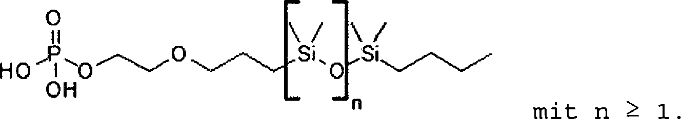
Gemäß zumindest einer Ausführungsform weist die phosphonathaltige Ligandenhülle ein endständiges phenylfunktionalisiertes Siloxanphosphat auf, das kovalent an den Kern der Quantenpunkte gebunden ist.In accordance with at least one embodiment, the phosphonate-containing ligand shell has a terminal phenyl-functionalized siloxane phosphate covalently bound to the core of the quantum dots.
Gemäß zumindest einer Ausführungsform erfolgt der Ligandenaustausch der ersten Ligandenhülle in eine anorganische Ligandenhülle. Vorzugsweise werden die Quantenpunkte mittels Hot Injection erzeugt. Die Quantenpunkte weisen dann eine erste Ligandenhülle, die vorzugsweise organisch ist, auf. Diese organische erste Ligandenhülle wird durch eine anorganische Ligandenhülle, insbesondere anhand des HSAB-Prinzips ausgetauscht. Gallium-Ionen sind beispielsweise hart, OH–-Ionen sind weich. Anschließend kann die Einkapselung dieser modifizierten Quantenpunkte in Silika erfolgen und eine Einbringbarkeit in ein Matrixmaterial erhöht werden. Es erfolgt keine signifikante Erniedrigung von dem Brechungsindex, da keine langen Alkylreste vorhanden sind. Die Ligandenhüllen bieten eine Barriere gegenüber Umwelteinflüssen und gewährleisten eine gute Einbringbarkeit der Quantenpunkte in das Matrixmaterial, das beispielsweise einen Brechungsindex von 1,53 aufweist, auf. Alternativ kann die erste Ligandenhülle der im Schritt A) bereitgestellten Quantenpunkte durch eine phosphonathaltige Ligandenhülle ausgetauscht werden. Beispielsweise kann die erste Ligandenhülle Ölsäure aufweisen und durch Phosphonatliganden verdrängt werden. Insbesondere handelt es sich bei den Phosphonatliganden um phenylfunktionalisierte Siloxanphosphonatliganden. Der Brechungsindex der phenylfunktionalisierten Siloxanphosphonatliganden entspricht im Wesentlichen dem Brechungsindex des Matrixmaterials, sodass daher eine leichte Einbringbarkeit der modifizierten Quantenpunkte in das Matrixmaterial erfolgen kann und keine Streuung an den Grenzflächen erfolgt.In accordance with at least one embodiment, the ligand exchange of the first ligand shell takes place in an inorganic ligand shell. Preferably, the quantum dots are generated by means of hot injection. The quantum dots then have a first ligand shell, which is preferably organic. This organic first ligand shell is characterized by an inorganic ligand shell, in particular by the HSAB principle replaced. For example, gallium ions are hard, OH - ions are soft. Subsequently, the encapsulation of these modified quantum dots in silica can take place and an applicability to a matrix material can be increased. There is no significant decrease in the refractive index since no long alkyl radicals are present. The ligand shells provide a barrier to environmental influences and ensure good applicability of the quantum dots in the matrix material, for example, has a refractive index of 1.53 on. Alternatively, the first ligand shell of the quantum dots provided in step A) can be exchanged for a phosphonate-containing ligand shell. For example, the first ligand shell may have oleic acid and be displaced by phosphonate ligands. In particular, the phosphonate ligands are phenyl-functionalized siloxane phosphonate ligands. The refractive index of the phenyl-functionalized Siloxanphosphonatliganden substantially corresponds to the refractive index of the matrix material, so therefore easy Einbringbarkeit the modified quantum dots in the matrix material can be done and no scattering occurs at the interfaces.
Gemäß zumindest einer Ausführungsform werden die Quantenpunkte im Schritt A) durch Direct Hot Injection hergestellt, wobei Ph3Si-PDPS (Ph = Phenyl; PDPS = Polydiphenylsiloxan) als Stabilisierungsreagenz zugesetzt wird. Alternativ, da einfacher zugänglich, wird momentan das PDMS-Analogon verwendet werden, also PDMS-Phosphat (PDMS = Polydimethylsiloxan) mit unterschiedlicher PDMS-Kettenlänge, beispielsweise mit 5 kD und 10 kDa: 
Die Erfinder haben erkannt, dass neben dem Ligandenaustausch auch Phenylsiloxanphosphonatliganden bzw. momentan das oben dargestellte PDMS-Phosphat direkt als Stabilisierungsreagenz in der Hot Injection Synthese verwendet werden können und diese die phosphonathaltige Ligandenhülle bilden. Damit muss kein Ligandenaustausch erfolgen und die Einmischung oder Einbringbarkeit in ein Matrixmaterial ist leichter verglichen mit Quantenpunkten, die im Schritt A) des Verfahrens erzeugt sind.The inventors have recognized that, in addition to the ligand exchange, phenylsiloxane phosphonate ligands or, at the moment, the above-described PDMS phosphate can also be used directly as a stabilization reagent in hot injection synthesis, and these form the phosphonate-containing ligand shell. Thus, there is no need for ligand exchange and the incorporation or incorporation into a matrix material is easier compared to quantum dots generated in step A) of the process.
Gemäß zumindest einer Ausführungsform erfolgt die Herstellung des Auskoppelelements und der Quantenpunkte durch Direct Hot Injection mit Triphenylsiliziumpolydiphenylsiloxanphosphonat oder entsprechend. Es wird insbesondere kein Trioctylphosphinoxid (TOPO) verwendet. Diese Phenylsiloxanliganden weisen einen ähnlichen Brechungsindex oder im Wesentlichen gleichen Brechungsindex als der Brechungsindex des Matrixmaterials auf, sodass diese miteinander kompatibel sind.In accordance with at least one embodiment, the coupling element and the quantum dots are produced by direct hot injection with triphenylsilicon polydiphenylsiloxane phosphonate or correspondingly. In particular, no trioctylphosphine oxide (TOPO) is used. These phenylsiloxane ligands have a similar refractive index or index of refraction as the refractive index of the matrix material, so that they are compatible with each other.

Durch das hier beschriebene Auskoppelelement kann die Auskoppeleffizienz, vorzugsweise der von einem Halbleiterchip emittierten Strahlung, erhöht werden.By means of the outcoupling element described here, the coupling-out efficiency, preferably of the radiation emitted by a semiconductor chip, can be increased.
Es wird ferner ein Auskoppelelement angegeben. Vorzugsweise wird das Auskoppelelement mit dem hier beschriebenen Verfahren hergestellt.Furthermore, a decoupling element is specified. Preferably, the decoupling element is produced by the method described here.
Gemäß zumindest einer Ausführungsform weist das Auskoppelelement ein Matrixmaterial, das ein hochbrechendes Silikon ist, auf. Als hochbrechendes Silikon wird hier insbesondere ein Silikon mit einem Brechungsindex n > 1.53 bezeichnet. In dem Matrixmaterial sind Quantenpunkte eingebettet. Die Quantenpunkte weisen jeweils einen Kern aus Galliumphosphid oder Indiumphosphid auf. Der jeweilige Kern weist eine Ligandenhülle aus Silika oder phenylfunktionalisiertes Siloxanphosphonat auf. Durch diese Ligandenhülle ist die Einbringbarkeit der Quantenpunkte in das Matrixmaterial erleichtert, verglichen mit Quantenpunkten, die keine derartige Ligandenhülle aufweisen oder die eine Ligandenhülle beispielsweise aus Ölsäure aufweisen. Das Auskoppelelement ist transparent für Strahlung aus dem roten und/oder IR-Bereich.In accordance with at least one embodiment, the decoupling element has a matrix material which is a high refractive index silicone. As a high refractive index silicone is here in particular a silicone with a refractive index n> 1.53 called. Quantum dots are embedded in the matrix material. The quantum dots each have a core of gallium phosphide or indium phosphide. The respective core has a ligand shell of silica or phenyl-functionalized siloxane phosphonate. Through this ligand shell is facilitates the applicability of the quantum dots in the matrix material, compared with quantum dots that have no such ligand shell or have a ligand shell, for example, from oleic acid. The decoupling element is transparent to radiation from the red and / or IR region.
Strahlung aus dem roten Bereich meint hier und im Folgenden eine Wellenlänge von ca. 600 bis 780 nm, beispielsweise 660 nm (Hyper RED) oder 730 (Far Red). Darüberhinaus sind die GaP-Nanopartikel aufgrund ihrer Absorption bzw. Transparenz auch stufenlos einsetzbar für beispielsweise grün (ca. 540 nm) und gelb (ca. 590) bzw. alle relevanten Farbnuancen. Strahlung aus dem IR-Bereich meint hier und im Folgenden eine Wellenlänge von 750 bis 2000 nm, insbesondere 800 bis 950 nm.Radiation from the red region here and below means a wavelength of approximately 600 to 780 nm, for example 660 nm (Hyper RED) or 730 (Far Red). Moreover, because of their absorption or transparency, the GaP nanoparticles are also infinitely variable for, for example, green (about 540 nm) and yellow (about 590) or all relevant color shades. Radiation from the IR range here and below means a wavelength of 750 to 2000 nm, in particular 800 to 950 nm.
Gemäß zumindest einer Ausführungsform weisen die Quantenpunkte mit Kern und Ligandenhülle die folgende Formel auf: 
Alternantiv weist die Ligandenhülle der Quantenpunkte die folgende Strukturformel auf: 
Weitere Vorteile, vorteilhafte Ausführungsformen und Weiterbildungen ergeben sich aus den im Folgenden in Verbindung mit den Figuren beschriebenen Ausführungsbeispielen.Further advantages, advantageous embodiments and developments emerge from the embodiments described below in conjunction with the figures.
Es zeigen:Show it:
Die
die
die
die
die
In den Ausführungsbeispielen und Figuren können gleiche, gleichartige oder gleich wirkende Elemente jeweils mit denselben Bezugszeichen versehen sein. Die dargestellten Elemente und deren Größenverhältnisse untereinander sind nicht als maßstabsgerecht anzusehen. Vielmehr können einzelne Elemente, wie zum Beispiel Schichten, Bauteile, Bauelemente und Bereiche, zur besseren Darstellbarkeit und/oder zum besseren Verständnis übertrieben groß dargestellt werden.In the exemplary embodiments and figures, identical, identical or identically acting elements can each be provided with the same reference numerals. The illustrated elements and their proportions with each other are not to be regarded as true to scale. Rather, individual elements, such as layers, components, components and areas for exaggerated representability and / or better understanding can be displayed exaggerated.
Die
Die
Die
Die
Die
Die
Die
Gemäß zumindest einer Ausführungsform des Halbleiterchips
Im Strahlengang des Halbleiterchips
Die
Die
Die
Die
Die
Die in Verbindung mit den Figuren beschriebenen Ausführungsbeispiele und deren Merkmale können gemäß weiterer Ausführungsbeispiele auch miteinander kombiniert werden. Auch wenn solche Kombinationen nicht explizit in den Figuren gezeigt sind. Weiterhin können die in Verbindung mit den Figuren beschriebenen Ausführungsbeispiele zusätzliche oder alternative Merkmale gemäß der Beschreibung im allgemeinen Teil aufweisen.The embodiments described in connection with the figures and their features can also be combined with each other according to further embodiments. Even if such combinations are not explicitly shown in the figures. Furthermore, the embodiments described in connection with the figures may have additional or alternative features as described in the general part.
Die Erfindung ist nicht durch die Beschreibung anhand der Ausführungsbeispiele auf diese beschränkt. Vielmehr umfasst die Erfindung jedes neue Merkmal sowie jede Kombination von Merkmalen, was insbesondere jede Kombination von Merkmalen in den Patentansprüchen beinhaltet, auch wenn dieses Merkmal oder diese Kombination selbst nicht explizit in den Patentansprüchen oder Ausführungsbeispielen angegeben ist.The invention is not limited by the description based on the embodiments of these. Rather, the invention encompasses any novel feature as well as any combination of features, including in particular any combination of features in the claims, even if this feature or combination itself is not explicitly stated in the patent claims or exemplary embodiments.
BezugszeichenlisteLIST OF REFERENCE NUMBERS
- 100100
- optoelektronisches Bauelementoptoelectronic component
- 11
- Substratsubstratum
- 22
- HalbleiterchipSemiconductor chip
- 33
- Linselens
- 44
- Ausnehmungrecess
- 55
- Gehäusecasing
- 66
- Vergussgrouting
- 77
- Quantenpunktequantum dots
- 7171
- Kerncore
- 7272
- anorganische oder phosphonathaltige Ligandenhülleinorganic or phosphonate-containing ligand shell
- 7373
- erste Ligandenhüllefirst ligand shell
- 88th
- Matrixmaterialmatrix material
- 99
- Auskoppelelementoutcoupling
- 1010
- Stabilisierungsreagenzstabilizing
Claims (14)


Priority Applications (4)
| Application Number | Priority Date | Filing Date | Title |
|---|---|---|---|
| DE102016117885.3A DE102016117885A1 (en) | 2016-09-22 | 2016-09-22 | Method for producing a decoupling element for an optoelectronic component and decoupling element |
| CN201780058649.0A CN109791969B (en) | 2016-09-22 | 2017-09-20 | Method for producing a coupling-out element of an optoelectronic component and coupling-out element |
| PCT/EP2017/073807 WO2018054992A1 (en) | 2016-09-22 | 2017-09-20 | Method for producing an outcoupling element for an optoelectronic component, and outcoupling element |
| US16/334,411 US11075324B2 (en) | 2016-09-22 | 2017-09-20 | Method of producing an outcoupling element for an optoelectronic component and outcoupling element |
Applications Claiming Priority (1)
| Application Number | Priority Date | Filing Date | Title |
|---|---|---|---|
| DE102016117885.3A DE102016117885A1 (en) | 2016-09-22 | 2016-09-22 | Method for producing a decoupling element for an optoelectronic component and decoupling element |
Publications (1)
| Publication Number | Publication Date |
|---|---|
| DE102016117885A1 true DE102016117885A1 (en) | 2018-04-12 |
Family
ID=60117625
Family Applications (1)
| Application Number | Title | Priority Date | Filing Date |
|---|---|---|---|
| DE102016117885.3A Pending DE102016117885A1 (en) | 2016-09-22 | 2016-09-22 | Method for producing a decoupling element for an optoelectronic component and decoupling element |
Country Status (4)
| Country | Link |
|---|---|
| US (1) | US11075324B2 (en) |
| CN (1) | CN109791969B (en) |
| DE (1) | DE102016117885A1 (en) |
| WO (1) | WO2018054992A1 (en) |
Families Citing this family (4)
| Publication number | Priority date | Publication date | Assignee | Title |
|---|---|---|---|---|
| DE102017102477B4 (en) | 2017-02-08 | 2022-01-20 | OSRAM Opto Semiconductors Gesellschaft mit beschränkter Haftung | Method for producing a decoupling element for an optoelectronic component and decoupling element |
| CN110888259A (en) * | 2019-11-27 | 2020-03-17 | Tcl华星光电技术有限公司 | Display module and preparation method thereof, and display device |
| JP7355724B2 (en) * | 2020-12-07 | 2023-10-03 | 信越化学工業株式会社 | Quantum dot surface treatment method and surface treatment device |
| WO2025088985A1 (en) * | 2023-10-26 | 2025-05-01 | 信越化学工業株式会社 | Quantum dot body, quantum dot composition, and wavelength conversion material and production method thereof |
Citations (2)
| Publication number | Priority date | Publication date | Assignee | Title |
|---|---|---|---|---|
| US20150085490A1 (en) * | 2011-06-20 | 2015-03-26 | Crystalplex Corporation | Quantum dot containing light module |
| US9306110B2 (en) * | 2013-07-31 | 2016-04-05 | US Nano LLC | Apparatus and methods for continuous flow synthesis of semiconductor nanowires |
Family Cites Families (6)
| Publication number | Priority date | Publication date | Assignee | Title |
|---|---|---|---|---|
| US20030066998A1 (en) * | 2001-08-02 | 2003-04-10 | Lee Howard Wing Hoon | Quantum dots of Group IV semiconductor materials |
| TW201341440A (en) | 2004-06-08 | 2013-10-16 | Sandisk Corp | Post-deposition encapsulation of nanostructures: compositions, devices and systems incorporating same |
| CN104387772B (en) | 2009-05-01 | 2017-07-11 | 纳米系统公司 | For the scattered functionalization of matrices of nanostructure |
| CN104755586B (en) | 2012-10-25 | 2018-02-06 | 皇家飞利浦有限公司 | The part based on PDMS for the quantum dot in silicone |
| US9722147B2 (en) | 2013-07-03 | 2017-08-01 | Pacific Light Technologies Corp. | Network of semiconductor structures with fused insulator coating |
| WO2017096229A1 (en) * | 2015-12-02 | 2017-06-08 | Nanosys, Inc. | Quantum dot encapsulation techniques |
-
2016
- 2016-09-22 DE DE102016117885.3A patent/DE102016117885A1/en active Pending
-
2017
- 2017-09-20 WO PCT/EP2017/073807 patent/WO2018054992A1/en not_active Ceased
- 2017-09-20 US US16/334,411 patent/US11075324B2/en active Active
- 2017-09-20 CN CN201780058649.0A patent/CN109791969B/en active Active
Patent Citations (2)
| Publication number | Priority date | Publication date | Assignee | Title |
|---|---|---|---|---|
| US20150085490A1 (en) * | 2011-06-20 | 2015-03-26 | Crystalplex Corporation | Quantum dot containing light module |
| US9306110B2 (en) * | 2013-07-31 | 2016-04-05 | US Nano LLC | Apparatus and methods for continuous flow synthesis of semiconductor nanowires |
Also Published As
| Publication number | Publication date |
|---|---|
| WO2018054992A1 (en) | 2018-03-29 |
| US20190221722A1 (en) | 2019-07-18 |
| CN109791969B (en) | 2022-08-19 |
| CN109791969A (en) | 2019-05-21 |
| US11075324B2 (en) | 2021-07-27 |
Similar Documents
| Publication | Publication Date | Title |
|---|---|---|
| DE112018000566B4 (en) | METHOD FOR PRODUCING A SEMICONDUCTOR STRUCTURE COMPRISING A QUANTUM POINT WITH COATING, CORRESPONDING SEMICONDUCTOR STRUCTURE AND LIGHTING DEVICE | |
| DE102015109947B4 (en) | Hybrid nanostructured particle, production method thereof and device with the hybrid nanostructured particle | |
| DE102005061828B4 (en) | Wavelength-converting converter material, light-emitting optical component and method for its production | |
| WO2018054992A1 (en) | Method for producing an outcoupling element for an optoelectronic component, and outcoupling element | |
| DE102014102848B4 (en) | Conversion element, method for producing a conversion element, optoelectronic component comprising a conversion element | |
| KR20140102211A (en) | Composite having semiconductor structutres embedded in a matrix | |
| DE112013001866B4 (en) | Optoelectronic component comprising a converter carrier layer, and method for producing an optoelectronic component comprising a converter carrier layer | |
| DE102015121720A1 (en) | Conversion element, optoelectronic component and method for producing a conversion element | |
| WO2016087656A1 (en) | Conversion element, optoelectronic semiconductor component and method for producing conversion elements | |
| DE112017000676T5 (en) | Method and apparatus for applying light and heat to quantum dots to increase quantum efficiency | |
| DE112019002462T5 (en) | METHOD OF MANUFACTURING A CONVERTER ELEMENT, CONVERTER ELEMENT, AND LIGHT-EMITTING DEVICE | |
| DE102016104790A1 (en) | Materials for LED encapsulation | |
| DE102012103159A1 (en) | Radiation emitting device, transparent material and filler particles and their production process | |
| DE102012106984A1 (en) | Optoelectronic semiconductor component and method for producing an optoelectronic semiconductor component | |
| DE112017002467B4 (en) | LIGHTING DEVICES WITH A LENS AND A COMPOSITE ENCAPSULATING AND METHOD FOR PRODUCING THE SAME | |
| WO2021122321A1 (en) | Optoelectronic semi-conductor element and method for operating an optoelectronic semi-conductor element | |
| DE102017121185A1 (en) | Optoelectronic component and method for producing an optoelectronic component | |
| DE102018106465B4 (en) | Optoelectronic component | |
| DE112020006175T5 (en) | Semiconductor nanoparticle aggregate, semiconductor nanoparticle aggregate dispersion liquid, semiconductor nanoparticle aggregate composition and semiconductor nanoparticle aggregate cured film | |
| DE102017102477B4 (en) | Method for producing a decoupling element for an optoelectronic component and decoupling element | |
| DE102012103393A1 (en) | Transparent body, optoelectronic component with a transparent body and method for producing a transparent body | |
| DE112020004575T5 (en) | CONVERSION LAYER, LIGHT-EMITTING COMPONENT AND METHOD FOR MANUFACTURING A CONVERSION LAYER | |
| WO2020074328A1 (en) | Enveloping material, conversion material, optoelectronic component and method for producing an enveloping material | |
| WO2020144029A1 (en) | Radiation-emitting component and method for producing a radiation-emitting component | |
| DE112022003871T5 (en) | STRUCTURE, AGGLOMERATE, OPTOELECTRONIC COMPONENT AND METHOD FOR PRODUCING A STRUCTURE AND AN AGGLOMERATE |
Legal Events
| Date | Code | Title | Description |
|---|---|---|---|
| R163 | Identified publications notified | ||
| R012 | Request for examination validly filed | ||
| R016 | Response to examination communication | ||
| R079 | Amendment of ipc main class |
Free format text: PREVIOUS MAIN CLASS: H01L0033520000 Ipc: H10H0020852000 |