CN203203668U - A cantilever beam weighing sensor with bi-symmetric cantilevers - Google Patents
A cantilever beam weighing sensor with bi-symmetric cantilevers Download PDFInfo
- Publication number
- CN203203668U CN203203668U CN 201320054645 CN201320054645U CN203203668U CN 203203668 U CN203203668 U CN 203203668U CN 201320054645 CN201320054645 CN 201320054645 CN 201320054645 U CN201320054645 U CN 201320054645U CN 203203668 U CN203203668 U CN 203203668U
- Authority
- CN
- China
- Prior art keywords
- cantilever
- free end
- fixed
- rigid body
- fixed end
- Prior art date
- Legal status (The legal status is an assumption and is not a legal conclusion. Google has not performed a legal analysis and makes no representation as to the accuracy of the status listed.)
- Expired - Fee Related
Links
- 238000005303 weighing Methods 0.000 title abstract description 18
- 239000011888 foil Substances 0.000 claims description 13
- 230000003139 buffering effect Effects 0.000 abstract 1
- NJPPVKZQTLUDBO-UHFFFAOYSA-N novaluron Chemical compound C1=C(Cl)C(OC(F)(F)C(OC(F)(F)F)F)=CC=C1NC(=O)NC(=O)C1=C(F)C=CC=C1F NJPPVKZQTLUDBO-UHFFFAOYSA-N 0.000 abstract 1
- 230000002035 prolonged effect Effects 0.000 abstract 1
- 230000035945 sensitivity Effects 0.000 abstract 1
- 238000009434 installation Methods 0.000 description 5
- 238000010586 diagram Methods 0.000 description 4
- 238000010276 construction Methods 0.000 description 2
- 229910000831 Steel Inorganic materials 0.000 description 1
- 208000027418 Wounds and injury Diseases 0.000 description 1
- 230000009286 beneficial effect Effects 0.000 description 1
- 230000015572 biosynthetic process Effects 0.000 description 1
- 230000006378 damage Effects 0.000 description 1
- 238000006073 displacement reaction Methods 0.000 description 1
- 230000000694 effects Effects 0.000 description 1
- 238000005516 engineering process Methods 0.000 description 1
- 208000014674 injury Diseases 0.000 description 1
- 239000007787 solid Substances 0.000 description 1
- 239000010959 steel Substances 0.000 description 1
Images
Landscapes
- Measurement Of Force In General (AREA)
Abstract
The utility model belongs to the field of weighing machinery, and specifically relates to a cantilever beam weighing sensor with bi-symmetric cantilevers. The cantilever beam weighing sensor is characterized by comprising N cantilever beams and a rigid body pedestal, wherein the N is no smaller than 1. Each cantilever beam includes a fixed end, a cantilever and a free end, wherein the free end is positioned at one end of the cantilever, and the fixed end is positioned at the other end of the cantilever; the fixed end is provided with at least two threaded holes which vertically penetrate through the fixed end; the cantilever and the fixed end are fixed on the rigid body; two symmetrical blind holes are arranged in the cantilever between the fixed end and the free end; and strain gauges are disposed at the bottoms of the blind holes. The cantilever beam weighing sensor is simple in structure and convenient to carry out. Since the pair of blind holes are disposed at symmetrical positions on two sides of the cantilevers between each fixed end and each free end, and strain gauges are adhered into the blind holes, sensitivity and stability of the weighing sensor with double cantilevers are improved, and accuracy of weighing is improved too. A force-bearing head is disposed at the free end of each cantilever and is disposed on the cantilever through a groove; a seal ring is arranged between the force-bearing head and the groove, so that exhausting speed of air is slowed down, the speed of the force-bearing head sinking into the groove is thus slowed down, and the service life of the equipment is prolonged with buffering effect of air pressure.
Description
Technical field
The utility model belongs to the weighing-appliance field, is specifically related to a kind of disymmetry arm sling beam load cell.
Background technology
At present, truck scale, the main shop formula axle load meter of semi-girder LOAD CELLS in highway weighing apparatus, fields such as the platform scale in the industrial weighing machinery, steel cylinder scale have been used widely, and it has advantages such as measuring accuracy height, setting height(from bottom) is low, mounting structure is simple, Costco Wholesale is low.The profile of traditional semi-girder LOAD CELLS is the cuboid structure, wherein an end for do not produce axially, the stiff end of perpendicular displacement and rotation, the other end is free force side, two blind holes of symmetria bilateralis distribution in the middle of the cantilever between solid fulcrum and the force side, foil gauge is posted in the blind hole bottom, and can form the Hui Sideng full-bridge circuit, when free force side is stressed, blind hole bottom foil gauge resistance can change, cause Hui Sideng full-bridge circuit output voltage to change, and then convert the variation of gravimetric value to; Traditional semi-girder LOAD CELLS only comprises a hold-down support and a free force side, limited and very inconvenient need use the weighing platform of many sensors to use simultaneously the time in some installation site, even there is enough big space that many sensors are installed simultaneously in order to satisfy, and needs strengthen the physical dimension of weighing platform, the general shape size of weighing platform is increased, increased self cost, field engineering amount and the installation difficulty of weighing platform.
The utility model content
It is limited and need use when using on the weighing platform of many sensors very inconvenient simultaneously that the utility model is deposited some installation site at prior art, even there is enough big space that many sensors are installed simultaneously in order to satisfy, and needs strengthen the physical dimension of weighing platform, the general shape size of weighing platform is increased, increase the problem of self cost, field engineering amount and the installation difficulty of weighing platform, proposed a kind of disymmetry arm sling beam load cell.
The technical solution of the utility model is: a kind of disymmetry arm sling beam load cell, comprise N semi-girder and rigid body base, N 〉=1, wherein semi-girder comprises, stiff end, cantilever and free end, free end is positioned at an end of cantilever, stiff end is positioned at the other end of cantilever, on stiff end, be provided with two threaded holes that vertically run through stiff end at least, the cantilever stiff end is fixed on the rigid body, on the cantilever between stiff end and the free end, be provided with the blind hole of two symmetries, the bottom of blind hole is provided with foil gauge.
Described disymmetry arm sling beam load cell, described N semi-girder intersect and are fixed on the rigid body base side by side or same direction is fixed on the rigid body base N 〉=2 side by side.
Described disymmetry arm sling beam load cell, the upside of cantilever free end is connected with stress head, and stress head is fixed on the free end by the groove on the free end, is provided with O-ring seal between stress head and the groove.
Described disymmetry arm sling beam load cell, the sidewall of semi-girder stiff end is provided with the outlet cable, every group of corresponding outlet cable of foil gauge.
The beneficial effects of the utility model are: 1. the utility model is simple in structure, it is convenient to implement, the a pair of blind hole in the monosymmetric position of cantilever between stiff end and free end, the blind hole the inside is pasted with foil gauge, improve susceptibility and the stability of two cantilever module LOAD CELLS, improved accuracy of weighting.
2. the free end of cantilever of the present utility model is provided with stress head, stress head is fixed on the cantilever by groove, between stress head and groove, be lined with O-ring seal, slow down the efflux velocity of air, and then slow down stress head and sink the into speed of groove, play the effect of pressure buffer, reduce bump to the injury of cantilever, improve the serviceable life of equipment.
3. a plurality of semi-girders of the utility model intersect and are fixed on the rigid body base side by side or same direction is fixed on the rigid body base side by side, solved the limited and very inconvenient problem need use the weighing platform of many sensors to use simultaneously the time in some installation site, satisfy in limited space many sensors are installed simultaneously, improved utilization of space.
Description of drawings
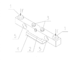
Fig. 1 is monoblock type double cantilever beam sensor construction synoptic diagram;
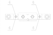
Fig. 2 is split type double cantilever beam sensor cross structure synoptic diagram;
Fig. 3 is the staggered parallel construction synoptic diagram of split type double cantilever beam sensor;
Fig. 4 is monoblock type double cantilever beam sensors sides structural representation;
Fig. 5 is monoblock type double cantilever beam sensor plan structure perspective diagram;
Among the figure, 1 is free end, and 2 is stiff end, and 3 is bolt, and 4 is the rigid body bearing, and 5 is blind hole, and 6 is foil gauge.
Embodiment
Embodiment 1: in conjunction with Fig. 2, Fig. 3, Fig. 4, Fig. 5, a kind of disymmetry arm sling beam load cell, comprise 2 semi-girders and rigid body base, wherein semi-girder comprises, stiff end, cantilever and free end, free end are positioned at an end of cantilever, stiff end is positioned at the other end of cantilever, at least be provided with two threaded holes that vertically run through stiff end on stiff end, the cantilever stiff end is fixed on the rigid body, on the cantilever between stiff end and the free end, be provided with the blind hole of two symmetries, the bottom of blind hole is provided with foil gauge.
2 semi-girders intersect and are fixed on the rigid body base side by side or same direction is fixed on the rigid body base side by side; The upside of cantilever free end is connected with stress head, stress head is fixed on the free end by the groove on the free end, be provided with O-ring seal between stress head and the groove, the sidewall of semi-girder stiff end is provided with the outlet cable, every group of corresponding outlet cable of foil gauge.
Claims (4)
1. disymmetry arm sling beam load cell, it is characterized in that: comprise N semi-girder and rigid body base, N 〉=1, wherein semi-girder comprises, stiff end, cantilever and free end, free end is positioned at an end of cantilever, and stiff end is positioned at the other end of cantilever, is provided with two threaded holes that vertically run through stiff end on stiff end at least, the cantilever stiff end is fixed on the rigid body, on the cantilever between stiff end and the free end, be provided with the blind hole of two symmetries, the bottom of blind hole is provided with foil gauge.
2. disymmetry arm sling beam load cell according to claim 1 is characterized in that: described N semi-girder intersects and is fixed on the rigid body base side by side or same direction is fixed on the rigid body base N 〉=2 side by side.
3. disymmetry arm sling beam load cell according to claim 1, it is characterized in that: the upside of cantilever free end is connected with stress head, and stress head is fixed on the free end by the groove on the free end, is provided with O-ring seal between stress head and the groove.
4. disymmetry arm sling beam load cell according to claim 1, it is characterized in that: the sidewall of semi-girder stiff end is provided with the outlet cable, every group of corresponding outlet cable of foil gauge.
Priority Applications (1)
| Application Number | Priority Date | Filing Date | Title |
|---|---|---|---|
| CN 201320054645 CN203203668U (en) | 2013-01-31 | 2013-01-31 | A cantilever beam weighing sensor with bi-symmetric cantilevers |
Applications Claiming Priority (1)
| Application Number | Priority Date | Filing Date | Title |
|---|---|---|---|
| CN 201320054645 CN203203668U (en) | 2013-01-31 | 2013-01-31 | A cantilever beam weighing sensor with bi-symmetric cantilevers |
Publications (1)
| Publication Number | Publication Date |
|---|---|
| CN203203668U true CN203203668U (en) | 2013-09-18 |
Family
ID=49147768
Family Applications (1)
| Application Number | Title | Priority Date | Filing Date |
|---|---|---|---|
| CN 201320054645 Expired - Fee Related CN203203668U (en) | 2013-01-31 | 2013-01-31 | A cantilever beam weighing sensor with bi-symmetric cantilevers |
Country Status (1)
| Country | Link |
|---|---|
| CN (1) | CN203203668U (en) |
Cited By (5)
| Publication number | Priority date | Publication date | Assignee | Title |
|---|---|---|---|---|
| CN104132719A (en) * | 2014-07-14 | 2014-11-05 | 上海宇航系统工程研究所 | Variable-posture wheel pressure weighing device |
| CN108106952A (en) * | 2017-11-30 | 2018-06-01 | 江西洪都航空工业集团有限责任公司 | A kind of disymmetry section shock loading measuring method of beam |
| CN108896234A (en) * | 2018-05-21 | 2018-11-27 | 北京理工大学 | A kind of pipe pressure measurement method |
| CN110793602A (en) * | 2019-11-29 | 2020-02-14 | 宁波康铨利科技有限公司 | Integrated sensor for garbage classification |
| CN112924006A (en) * | 2021-01-28 | 2021-06-08 | 武汉工程大学 | Vehicle dynamic weighing sensor |
-
2013
- 2013-01-31 CN CN 201320054645 patent/CN203203668U/en not_active Expired - Fee Related
Cited By (8)
| Publication number | Priority date | Publication date | Assignee | Title |
|---|---|---|---|---|
| CN104132719A (en) * | 2014-07-14 | 2014-11-05 | 上海宇航系统工程研究所 | Variable-posture wheel pressure weighing device |
| CN104132719B (en) * | 2014-07-14 | 2017-03-29 | 上海宇航系统工程研究所 | Become attitude wheel load weighing device |
| CN108106952A (en) * | 2017-11-30 | 2018-06-01 | 江西洪都航空工业集团有限责任公司 | A kind of disymmetry section shock loading measuring method of beam |
| CN108106952B (en) * | 2017-11-30 | 2020-05-08 | 江西洪都航空工业集团有限责任公司 | Method for measuring impact load of beam with double symmetrical sections |
| CN108896234A (en) * | 2018-05-21 | 2018-11-27 | 北京理工大学 | A kind of pipe pressure measurement method |
| CN110793602A (en) * | 2019-11-29 | 2020-02-14 | 宁波康铨利科技有限公司 | Integrated sensor for garbage classification |
| CN112924006A (en) * | 2021-01-28 | 2021-06-08 | 武汉工程大学 | Vehicle dynamic weighing sensor |
| CN112924006B (en) * | 2021-01-28 | 2022-04-12 | 武汉工程大学 | Vehicle dynamic weighing sensor |
Similar Documents
| Publication | Publication Date | Title |
|---|---|---|
| CN203203668U (en) | A cantilever beam weighing sensor with bi-symmetric cantilevers | |
| CN101694407B (en) | Over-constrained large-range parallel six-dimensional force measuring platform | |
| CN103575446B (en) | A kind of Medium-measurement-rthree-dimensional three-dimensional force sensor | |
| CN104568279B (en) | A kind of multi-axis force transducer | |
| CN103308234B (en) | Internal force measuring sensor | |
| CN201935729U (en) | S-shaped weighing sensor | |
| CN207423488U (en) | A kind of big load piece box type balance for hold-down test | |
| CN102818729A (en) | Apparatus and method for detecting flexural bearing capacity of building wallboard | |
| CN102564549A (en) | Array piezoelectric sensor for dynamic weight measurement of vehicle | |
| CN110793603A (en) | Combined bridge type coupler multi-element multi-directional load measuring system and decoupling method | |
| CN105004454A (en) | Heavy-load single-component sensor and measuring method | |
| CN102175137A (en) | Extensometer for measuring micro-deformation of component | |
| CN111896164A (en) | Three-component force measuring sensor | |
| CN201765035U (en) | Torque Principle Two-dimensional Force Measuring Load Cell | |
| CN202649069U (en) | High-precision lever type weighing lysimeter system based on spring balance | |
| CN102410864B (en) | Load sensor | |
| CN108760108A (en) | Crane wheel pressure detection method based on stress survey technology | |
| CN101244790B (en) | Mechanical weighing mechanism of gantry crane dynamic grab bucket electronic weighing scale | |
| CN207095680U (en) | A kind of vehicle weighing sensor | |
| CN201277880Y (en) | Elastomer for integrated weighing sensor | |
| CN203310500U (en) | Novel flexible cup support structure with large-displacement for weighing large-scale object | |
| CN203284947U (en) | Composite type cushion pier structure for structure construction | |
| CN202109975U (en) | Weighing platform structure of weighing system | |
| CN203519064U (en) | A precise weighing and gravity center determination system for heavy objects | |
| CN105547868B (en) | The method of the structured testing impact force that drops hammer based on stress concentration principle |
Legal Events
| Date | Code | Title | Description |
|---|---|---|---|
| C14 | Grant of patent or utility model | ||
| GR01 | Patent grant | ||
| CF01 | Termination of patent right due to non-payment of annual fee | ||
| CF01 | Termination of patent right due to non-payment of annual fee |
Granted publication date: 20130918 Termination date: 20220131 |