CN102175137A - Extensometer for measuring micro-deformation of component - Google Patents
Extensometer for measuring micro-deformation of component Download PDFInfo
- Publication number
- CN102175137A CN102175137A CN 201010623280 CN201010623280A CN102175137A CN 102175137 A CN102175137 A CN 102175137A CN 201010623280 CN201010623280 CN 201010623280 CN 201010623280 A CN201010623280 A CN 201010623280A CN 102175137 A CN102175137 A CN 102175137A
- Authority
- CN
- China
- Prior art keywords
- strain gauge
- connection terminal
- extensometer
- terminal
- deformation
- Prior art date
- Legal status (The legal status is an assumption and is not a legal conclusion. Google has not performed a legal analysis and makes no representation as to the accuracy of the status listed.)
- Granted
Links
Images

Landscapes
- Measurement Of Length, Angles, Or The Like Using Electric Or Magnetic Means (AREA)
Abstract
一种测量构件微小变形的引伸计,该引伸计在被测构件上固定有刚性支架梁,在刚性支架梁上带有半椭圆环形弹性元件,且半椭圆环形弹性元件上设置有应变片组和接线端子组相连接组成惠斯通电桥,这样在被测构件表面发生微小变形时,该引伸计的刚性支架梁相邻的两个端部之间的距离发生和被测构件表面微小变形大小相同的变化,引发其上的应变片组也发生相应的变形,随后同步影响到其和对应的接线端子组相连接组成惠斯通电桥中的第三接线端子以及第四接线端子所构成的惠斯通电桥的输出信号电压,由此输出信号电压便可推算出被测构件的微小变形量下的应变,这样的引伸计的精度和线性度都能完全满足大构件的微小变形的测量要求,并且结构简单安装方便。
An extensometer for measuring the slight deformation of a component. The extensometer is fixed with a rigid support beam on the measured component, and has a semi-elliptical annular elastic element on the rigid support beam, and the semi-elliptical annular elastic element is provided with a set of strain gauges and The terminal groups are connected to form a Wheatstone bridge, so that when a slight deformation occurs on the surface of the measured component, the distance between the two adjacent ends of the rigid support beam of the extensometer changes in the same amount as the small deformation on the surface of the measured component , causing the corresponding deformation of the strain gauge group on it, and then synchronously affecting the connection between it and the corresponding terminal group to form the Wheatstone bridge formed by the third terminal and the fourth terminal in the Wheatstone bridge The output signal voltage, from which the output signal voltage can calculate the strain under the small deformation of the measured component, the accuracy and linearity of such an extensometer can fully meet the measurement requirements of small deformation of large components, and the structure is simple Easy to install.
Description
技术领域technical field
本发明涉及一种引伸计,具体涉及一种测量构件微小变形的引伸计。The invention relates to an extensometer, in particular to an extensometer for measuring small deformations of components.
背景技术Background technique
引伸计已广泛应用于石油开采工程、航天航空工程、土木建筑水利工程、桥梁与道路工程以及各个工程领域内大型设备的应力应变测量,现有的应变式引伸计的弹性元件结构,主要有三种:悬臂梁结构、刚性壁弓形结构或者柔性臂弓形结构。但是,这三种类型的引伸计的精度和线性度都不能完全满足大构件的微小变形的测量要求。Extensometers have been widely used in petroleum exploration engineering, aerospace engineering, civil engineering and water conservancy engineering, bridge and road engineering, and stress-strain measurement of large-scale equipment in various engineering fields. There are mainly three kinds of elastic element structures of existing strain-type extensometers. : cantilever beam structure, rigid wall arch structure or flexible arm arch structure. However, the accuracy and linearity of these three types of extensometers cannot fully meet the measurement requirements of small deformations of large components.
发明内容Contents of the invention
为了克服上述现有技术存在的不足,本发明的目的在于提供一种测量构件微小变形的引伸计,该引伸计在被测构件上固定有刚性支架梁,在刚性支架梁上带有半椭圆环形弹性元件,且半椭圆环形弹性元件上设置有应变片组和接线端子组相连接组成惠斯通电桥,这样在被测构件表面发生微小变形时,该引伸计的刚性支架梁相邻的两个端部之间的距离发生和被测构件表面微小变形大小相同的变化,这样引发其上的应变片组也发生相应的形变,随后同步影响到其和对应的接线端子组相连接组成惠斯通电桥中的第三接线端子以及第四接线端子所构成的惠斯通电桥的输出信号电压,由此输出信号电压便可得到被测构件的应变,这样的引伸计的精度和线性度都能完全满足大构件的微小变形的测量要求,并且结构简单安装方便。In order to overcome the deficiencies in the above-mentioned prior art, the object of the present invention is to provide an extensometer for measuring the slight deformation of a component. The extensometer is fixed with a rigid support beam on the measured component, and has a semi-elliptical ring on the rigid support beam. Elastic element, and the semi-elliptical annular elastic element is provided with a strain gauge group and a terminal group connected to form a Wheatstone bridge, so that when the surface of the measured member is slightly deformed, the two adjacent ends of the rigid support beam of the extensometer The distance between them changes in the same size as the small deformation of the surface of the measured component, which causes the corresponding deformation of the strain gauge group on it, and then synchronously affects its connection with the corresponding terminal group to form a Wheatstone bridge. The output signal voltage of the Wheatstone bridge composed of the third terminal and the fourth terminal of the terminal, the strain of the measured member can be obtained from the output signal voltage, the accuracy and linearity of such an extensometer can fully meet the requirements of large The measurement requirements of the small deformation of the component, and the structure is simple and easy to install.
为了达到上述目的,本发明所采用的技术方案是:In order to achieve the above object, the technical scheme adopted in the present invention is:
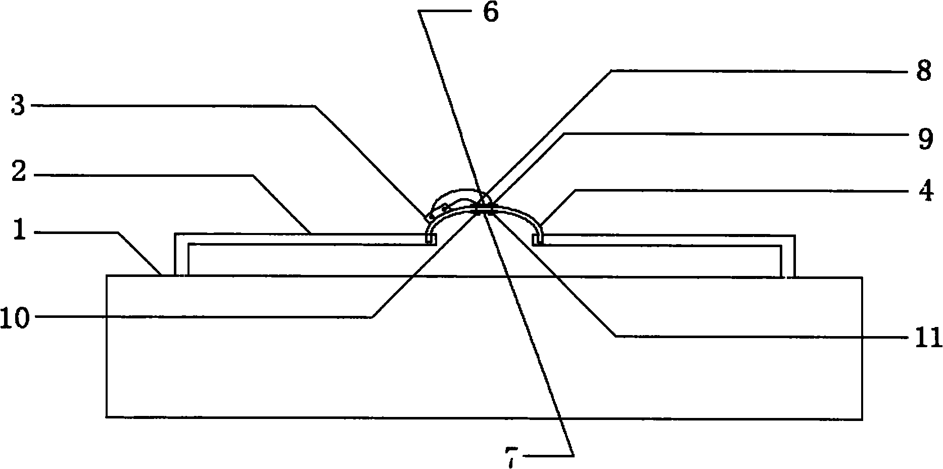
一种测量大构件微小变形的引伸计,在被测构件1上固定有两根左右对称的刚性支架梁2,该两根刚性支架梁2相邻的两个端部分别被半椭圆环形弹性元件4的两个端部的竖直延伸部分5嵌入而连接,半椭圆环形弹性元件4上设置有应变片组和对应的接线端子组3相连接组成惠斯通电桥。An extensometer for measuring the small deformation of a large component. Two left-right symmetrical
所述的引伸计通过下列公式得到被测构件1微小变形下的应变:The extensometer obtains the strain under the slight deformation of the measured
其中ε是被测构件待测应变,ΔL是被测构件1的待测微小变形,L是被测构件1的被测部分长度,Δl刚性支架梁2相邻的两个端部之间的距离变化,A是标定系数,U是惠斯通电桥的输出信号电压。Where ε is the measured strain of the measured member, ΔL is the measured small deformation of the measured
所述的应变片组含有第一应变片8、第二应变片9、第三应变片10和第四应变片11,第一应变片8和第二应变片9设置在半椭圆环形弹性元件4的顶部上表面6上,而第三应变片10和第四应变片11设置在半椭圆环形弹性元件4的顶部下表面7上。The strain gauge group includes a
所述的接线端子组3包括与供电正极相连接的第一接线端子12、与供电负极相连接的第二接线端子13、第三接线端子14以及第四接线端子15,所述的第一接线端子12和第三接线端子14同第一应变片8相连接,第一接线端子12还和第四应变片11相连接,第四应变片11和第四接线端子15相连接,第二接线端子13和第四接线端子15同第二应变片9相连接,第二接线端子13和第三接线端子14同第三应变片10相连接,所述的第三接线端子14以及第四接线端子15的电压输出构成惠斯通电桥的输出信号电压。The connecting
本发明的目的在于提供一种测量构件微小变形的引伸计,通过被测构件1表面发生微小变形时,该引伸计的刚性支架梁相邻的两个端部之间的距离发生和被测构件表面微小变形大小相同的变化,这样引发第一应变片8、第二应变片9、第三应变片10和第四应变片11也发生相应的变形,随后同步影响到其和对应的接线端子组3相连接组成惠斯通电桥中的第三接线端子14以及第四接线端子15所构成的惠斯通电桥的输出信号电压,由此输出信号电压便可推算出被测构件1的微小变形量下的应变,这样的引伸计的精度和线性度都能完全满足大构件的微小变形的测量要求,并且结构简单安装方便。The object of the present invention is to provide a kind of extensometer that measures the small deformation of component, when the surface of measured
附图说明Description of drawings
图1是本发明的测量构件微小变形的引伸计的结构图。Fig. 1 is a structural diagram of an extensometer for measuring small deformations of components according to the present invention.
图2是本发明的半椭圆环形弹性元件的主视结构示意图。Fig. 2 is a front structural schematic view of the semi-elliptical annular elastic element of the present invention.
图3是带有本发明的应变片组和对应的接线端子组的连接示意图。Fig. 3 is a schematic diagram showing the connection of the strain gauge set and the corresponding terminal set of the present invention.
具体实施方式Detailed ways
下面结合附图对本发明作更详细的说明。The present invention will be described in more detail below in conjunction with the accompanying drawings.
如图1和图2所示,测量大构件微小变形的引伸计,在被测构件1上固定有两根左右对称的刚性支架梁2,该两根刚性支架梁2相邻的两个端部分别被半椭圆环形弹性元件4的两个端部的竖直延伸部分5嵌入而连接,半椭圆环形弹性元件4上设置有应变片组和对应的接线端子组3相连接组成惠斯通电桥。所述的应变片组含有第一应变片8、第二应变片9、第三应变片10和第四应变片11,第一应变片8和第二应变片9设置在半椭圆环形弹性元件4的顶部上表面6上,而第三应变片10和第四应变片11设置在半椭圆环形弹性元件4的顶部下表面7上。所述的引伸计通过下列公式得到被测构件1微小变形下的应变:As shown in Figure 1 and Figure 2, the extensometer for measuring the small deformation of large components is fixed with two symmetrical
其中ε是被测构件待测应变,ΔL是被测构件1的待测微小变形,L是被测构件1的被测部分长度,Δl刚性支架梁2相邻的两个端部之间的距离变化,A是标定系数,U是惠斯通电桥的输出信号电压。Where ε is the measured strain of the measured member, ΔL is the measured small deformation of the measured
如图3所示,所述的接线端子组3包括与供电正极相连接的第一接线端子12、与供电负极相连接的第二接线端子13、第三接线端子14以及第四接线端子15,所述的第一接线端子12和第三接线端子14同第一应变片8相连接,第一接线端子12还和第四应变片11相连接,第四应变片11和第四接线端子15相连接,第二接线端子13和第四接线端子15同第二应变片9相连接,第二接线端子13和第三接线端子14同第三应变片10相连接,所述的第三接线端子14以及第四接线端子15的电压输出构成惠斯通电桥的输出信号电压。As shown in Figure 3, the
本发明的工作原理为:在被测构件1表面发生微小变形时,该引伸计的刚性支架梁相邻的两个端部之间的距离发生和被测构件表面微小变形大小相同的变化,这样引发第一应变片8、第二应变片9、第三应变片10和第四应变片11也发生相应的变形,随后同步影响到其和对应的接线端子组3相连接组成惠斯通电桥中的第三接线端子14以及第四接线端子15所构成的惠斯通电桥的输出信号电压,由此输出信号电压再根据公式The working principle of the present invention is: when the surface of the measured
便可得到被测构件1的微小变形量下的应变。The strain under the small deformation of the measured
本发明的目的在于提供一种测量构件微小变形的引伸计,通过被测构件1表面发生微小变形时,该引伸计的刚性支架梁相邻的两个端部之间的距离发生和被测构件表面微小变形大小相同的变化,这样引发第一应变片8、第二应变片9、第三应变片10和第四应变片11发生相应的变形,随后同步影响到其和对应的接线端子组3相连接组成惠斯通电桥中的第三接线端子14以及第四接线端子15所构成的输出信号电压,由此输出信号电压便可推算出被测构件1的微小变形量下的应变,这样的引伸计的精度和线性度都能完全满足大构件的微小变形的测量要求,并且结构简单安装方便。The object of the present invention is to provide a kind of extensometer that measures the small deformation of component, when the surface of measured
Claims (4)
Priority Applications (1)
| Application Number | Priority Date | Filing Date | Title |
|---|---|---|---|
| CN2010106232803A CN102175137B (en) | 2010-12-29 | 2010-12-29 | Extensometer for measuring micro-deformation of component |
Applications Claiming Priority (1)
| Application Number | Priority Date | Filing Date | Title |
|---|---|---|---|
| CN2010106232803A CN102175137B (en) | 2010-12-29 | 2010-12-29 | Extensometer for measuring micro-deformation of component |
Publications (2)
| Publication Number | Publication Date |
|---|---|
| CN102175137A true CN102175137A (en) | 2011-09-07 |
| CN102175137B CN102175137B (en) | 2012-06-13 |
Family
ID=44518347
Family Applications (1)
| Application Number | Title | Priority Date | Filing Date |
|---|---|---|---|
| CN2010106232803A Expired - Fee Related CN102175137B (en) | 2010-12-29 | 2010-12-29 | Extensometer for measuring micro-deformation of component |
Country Status (1)
| Country | Link |
|---|---|
| CN (1) | CN102175137B (en) |
Cited By (8)
| Publication number | Priority date | Publication date | Assignee | Title |
|---|---|---|---|---|
| CN104374469A (en) * | 2013-08-13 | 2015-02-25 | 北京鉴衡认证中心有限公司 | Strain foil type vibration sensor |
| CN104406514A (en) * | 2014-11-28 | 2015-03-11 | 广东欧珀移动通信有限公司 | Device and method for measuring bending deformation degree of article |
| CN105352799A (en) * | 2015-11-09 | 2016-02-24 | 浙江大学 | Double-tuning-fork-shaped elastomer extensometer and measuring method |
| CN108036712A (en) * | 2017-12-12 | 2018-05-15 | 中国人民解放军国防科技大学 | A light-weight and large-range extensometer and its application method |
| CN111166274A (en) * | 2013-10-24 | 2020-05-19 | 奥瑞斯健康公司 | Robotically-assisted endoluminal surgical systems and related methods |
| CN111272315A (en) * | 2020-03-20 | 2020-06-12 | 广东华兰海电测科技股份有限公司 | Vehicle axle stress collecting device and method |
| CN112504111A (en) * | 2020-11-25 | 2021-03-16 | 上海材料研究所 | Strain test system and method for flexible piezoelectric device |
| CN112923845A (en) * | 2021-03-24 | 2021-06-08 | 中国石油大学(华东) | Pipeline four-point strain acquisition belt device |
Citations (5)
| Publication number | Priority date | Publication date | Assignee | Title |
|---|---|---|---|---|
| US5962792A (en) * | 1997-06-02 | 1999-10-05 | The Penn State Research Foundation | Beam strain gauge |
| CN2475641Y (en) * | 2001-06-04 | 2002-02-06 | 北方交通大学 | Steel rail dynamic deformation measuring device |
| CN1484749A (en) * | 2001-01-10 | 2004-03-24 | 米其林技术公司 | Method and apparatus for assessing deformation and stress |
| DE102006013462A1 (en) * | 2005-04-01 | 2006-10-05 | Kistler, Walter P., Redmond | Deformation sensor for weighing system that compensates for thermal deformations, has deformation detection element mounted on corresponding bridge for connecting sensor body elements together |
| CN101059331A (en) * | 2006-04-18 | 2007-10-24 | 株式会社共和电业 | Strain gauge for measuring large strains |
-
2010
- 2010-12-29 CN CN2010106232803A patent/CN102175137B/en not_active Expired - Fee Related
Patent Citations (5)
| Publication number | Priority date | Publication date | Assignee | Title |
|---|---|---|---|---|
| US5962792A (en) * | 1997-06-02 | 1999-10-05 | The Penn State Research Foundation | Beam strain gauge |
| CN1484749A (en) * | 2001-01-10 | 2004-03-24 | 米其林技术公司 | Method and apparatus for assessing deformation and stress |
| CN2475641Y (en) * | 2001-06-04 | 2002-02-06 | 北方交通大学 | Steel rail dynamic deformation measuring device |
| DE102006013462A1 (en) * | 2005-04-01 | 2006-10-05 | Kistler, Walter P., Redmond | Deformation sensor for weighing system that compensates for thermal deformations, has deformation detection element mounted on corresponding bridge for connecting sensor body elements together |
| CN101059331A (en) * | 2006-04-18 | 2007-10-24 | 株式会社共和电业 | Strain gauge for measuring large strains |
Cited By (11)
| Publication number | Priority date | Publication date | Assignee | Title |
|---|---|---|---|---|
| CN104374469A (en) * | 2013-08-13 | 2015-02-25 | 北京鉴衡认证中心有限公司 | Strain foil type vibration sensor |
| CN111166274A (en) * | 2013-10-24 | 2020-05-19 | 奥瑞斯健康公司 | Robotically-assisted endoluminal surgical systems and related methods |
| CN111166274B (en) * | 2013-10-24 | 2025-01-28 | 奥瑞斯健康公司 | Robotic-assisted endoluminal surgical system and related methods |
| US12491042B2 (en) | 2013-10-24 | 2025-12-09 | Auris Health, Inc. | Endoscopic device with helical lumen design |
| CN104406514A (en) * | 2014-11-28 | 2015-03-11 | 广东欧珀移动通信有限公司 | Device and method for measuring bending deformation degree of article |
| CN104406514B (en) * | 2014-11-28 | 2017-06-20 | 广东欧珀移动通信有限公司 | A kind of device and method for measuring object Bending Deformation degree |
| CN105352799A (en) * | 2015-11-09 | 2016-02-24 | 浙江大学 | Double-tuning-fork-shaped elastomer extensometer and measuring method |
| CN108036712A (en) * | 2017-12-12 | 2018-05-15 | 中国人民解放军国防科技大学 | A light-weight and large-range extensometer and its application method |
| CN111272315A (en) * | 2020-03-20 | 2020-06-12 | 广东华兰海电测科技股份有限公司 | Vehicle axle stress collecting device and method |
| CN112504111A (en) * | 2020-11-25 | 2021-03-16 | 上海材料研究所 | Strain test system and method for flexible piezoelectric device |
| CN112923845A (en) * | 2021-03-24 | 2021-06-08 | 中国石油大学(华东) | Pipeline four-point strain acquisition belt device |
Also Published As
| Publication number | Publication date |
|---|---|
| CN102175137B (en) | 2012-06-13 |
Similar Documents
| Publication | Publication Date | Title |
|---|---|---|
| CN102175137A (en) | Extensometer for measuring micro-deformation of component | |
| CN101603865B (en) | Attached load cell | |
| CN103575446B (en) | A kind of Medium-measurement-rthree-dimensional three-dimensional force sensor | |
| CN101131335A (en) | Two-dimensional small range force sensor | |
| CN104568279B (en) | A kind of multi-axis force transducer | |
| CN102261889B (en) | Two-cantilever large-deformation strain measurement sensor | |
| CN104697677B (en) | A kind of piezomagnetic strain gauge | |
| CN206248252U (en) | A kind of anchor pole axial direction dynamometer | |
| CN106768523A (en) | A kind of press tonnage measuring method and its device | |
| CN105973510A (en) | Loader bucket stress test method | |
| CN103196526B (en) | Dynamometry weighing sensor with unbalance loading isolating function and isolating measuring method thereof | |
| CN108267118A (en) | A kind of strain-type intelligent inclinometer | |
| CN103575435A (en) | Three-dimensional force sensor used for automobile rear axle test system | |
| CN103921171B (en) | A kind of wide range piezoresistance type high-frequency rings fixed four component Milling Force sensors | |
| CN202101810U (en) | Tensile test device used for comparing calibration of stress sensor | |
| CN201844897U (en) | Digital 0.1-level tension and compression integrated standard dynamometer | |
| CN108759652B (en) | A kind of curvature measurement method based on favour stone full-bridge principle | |
| CN101344381B (en) | Miniature built-in stretching type optical fiber spring combination type displacement gage used for model experiment | |
| CN205120283U (en) | Tension appearance sensor | |
| CN102455229A (en) | High-precision sensor | |
| CN106092391B (en) | A kind of split type 2 D force sensor | |
| CN204575225U (en) | A kind of piezomagnetic strain gauge | |
| CN105157551A (en) | Triangle displacement sensor | |
| CN116576999B (en) | A six-dimensional force sensor based on shear strain detection using resistance strain gauge | |
| CN202974770U (en) | Young modulus measurer |
Legal Events
| Date | Code | Title | Description |
|---|---|---|---|
| C06 | Publication | ||
| PB01 | Publication | ||
| C10 | Entry into substantive examination | ||
| SE01 | Entry into force of request for substantive examination | ||
| C14 | Grant of patent or utility model | ||
| GR01 | Patent grant | ||
| CF01 | Termination of patent right due to non-payment of annual fee |
Granted publication date: 20120613 Termination date: 20141229 |
|
| EXPY | Termination of patent right or utility model |