[utility model content]
The purpose of this utility model is to provide a kind of electric connector with preferable anti-electromagnetic interference capability.
For achieving the above object, the utility model adopts following technical scheme: a kind of electric connector, it comprises body, some conducting terminals that are contained in body, first, second shielding casing and metal connecting sheet, described body comprises insulating base, this insulating base comprises accepting hole and forms the sidewall of this accepting hole, this sidewall is provided with the accepting groove of accommodating described brace, described first shielding casing is located in the described accepting hole, second shielding casing is coated on the periphery of insulating base, and this brace comprises first contact site that connects first shielding casing and second contact site that connects second shielding casing.
Compared with prior art, the utility model electric connector is contained in brace in the insulating base by setting, this brace electrically contacts with first, second shielding casing simultaneously, first shielding casing like this just can be soldered on the circuit board by the welding foot on second shielding casing and with first shielding casing ground connection simultaneously, thereby strengthened the anti-electromagnetic interference capability of electric connector.
[embodiment]
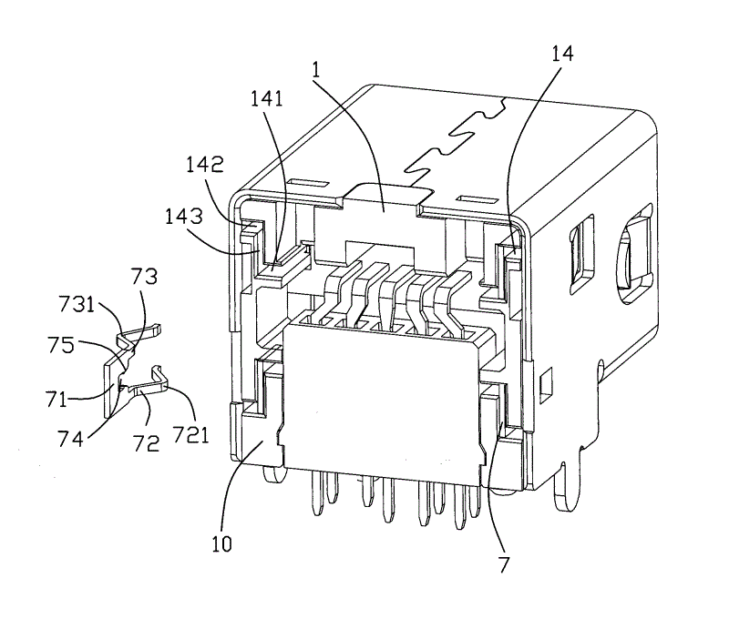
Join shown in Figure 1ly, the utility model electric connector comprises body 100, the some conducting terminal 3 of body 100, the shielding casing that is assembled in body 100 and some braces 7 of being contained in.
Ginseng Fig. 2,3, body 100 comprises an insulating base 1 and terminal module 2.Insulating base 1 is the hollow, rectangular structure, the rectangle accepting hole 11 that connects before and after its middle part is provided with, and this accepting hole 11 is enclosed by roof, diapire and left and right sides sidewall 12 and forms.The inner surface of roof and diapire is provided with groove 13, and the inner surface of described two side 12 is provided with the location notch 121 in order to locate described terminal module 2 that extends forward from pedestal 1 rear end face that insulate.The outer surface of two side 12 is provided with the draw-in groove 122 that extends forward from the pedestal rear end face that insulate.The diapire of described location notch 121 belows is provided with the groove 15 that extends back from the front end face of pedestal 1 of insulating.Diapire extends upward the breach 16 of the described accepting hole 11 of a perforation, and a positioning block 8 is plugged in this breach 16.Diapire is provided with the reference column that is inserted in circuit board 17 of downward extension.
Ginseng Fig. 2,3, described terminal module 2 passes described accepting hole 11 forward and is assembled in insulating base 1 from insulation pedestal 1 rear end face 10, this terminal module 2 comprises the hyoplastron 21 that two stacked on top are provided with, described conducting terminal 3 towards molded in hyoplastron 21, these two hyoplastrons 21 that pile up setting extend the front end face of insulating base 1 and form a docking part, and hyoplastron 21 both sides are provided with the projection 22 in the location notch that is positioned described insulating base 1 121 that extend forward the rear end.Described conducting terminal 3 comprises to be located at the contact site 31 on two hyoplastrons, 21 upper and lower two inner surfaces relatively and to extend hyoplastron 21 welding foots 32 outer and that extend downwards, these welding foot 32 corresponding inserted are positioned in the described locating piece 8, and the structure that terminal module 2 is assembled in insulating base 1 as shown in Figure 4.
Ginseng Fig. 2,3, shielding casing comprise first shielding casing 4 (being interior shielding casing in the present embodiment), second shielding casing 5 (being outer shielding casing in the present embodiment) and bonnet 6.Described first shielding casing 4 is coated on the periphery of hyoplastron 21, and in it, be formed with first receiving space, 41 (see figure 1)s, described second shielding casing 5 is coated on the peripheral of insulating base 1 and extends forward, with and first shielding casing 4 between form second receiving space, 51 (see figure 1)s, 6 of described bonnets are covered in to interlock on the rear end face 10 of insulating base 1 and with second shielding casing 5 and hold.First shielding casing, 4 rectangular frame structures, the left side plate 42 that it comprises upper plate and the lower plate on the upper and lower outer surface that is covered in hyoplastron 21 and is connected upper and lower plate.Be equipped with the retaining sheet 43 that extends back on this upper and lower plate, be respectively equipped with the shell fragment 44 that protrudes laterally on the biside plate 42, side plate 42 rear ends are provided with two adjutages 45,46 that extend back, and this two adjutage 45,46 is respectively adjacent to the upper and lower edge of side plate 42.Described first shielding casing 4 is in the front end face of the pedestal 1 that insulate inserts slit between insulating base 1 and the terminal module 2 backward, in this process, adjutage 46 inserts backward along described groove 15, two adjutages 45, about in the of 46 on the set projection 22 in clamping hyoplastron 21 both sides, and be immobilizated in projection 22 by hangnail set on it, this adjutage 45,46 terminal correspondence is resisted against described location notch about in the of 121 on the set link stopper 18 in both sides, 43 of described retaining sheets are immobilizated in by the set hangnail in its both sides in the holding slot 13 of described insulating base 1, so, first shielding casing 4 is just stable is immobilizated on the insulating base 1.
Ginseng Fig. 2,3, the second shielding casings 5 comprise that the top board that is covered on insulating base 1 roof, the side plate 52 that is covered on the insulating base two side reach the base plate relative with top board.Be respectively equipped with relatively to described shell fragment 44 projecting inward shell fragment 53 on the biside plate 52, shell fragment 53 rears are provided with the bent sheet 54 that is positioned in the described draw-in groove 122, and side plate is extended with the welding foot 55 that is inserted on the circuit board downwards.The button gripping arm 61 that extend forward described bonnet 6 both sides is provided with and is buckled on button set on the side plate 52 and holds holding part 62 in the hole 56, and so, bonnet 6 is just stable to be immobilizated on second shielding casing 5.
Ginseng Fig. 4, described brace 7 is Metal Flake structure, it is installed in the accepting groove 14 set on the sidewall 12 of insulating base 1.This accepting groove 14 runs through the rear end face 10 of insulating base 1, it comprises first holding slot 141 that runs through sidewall 12 inner surfaces, the link slot 143 that runs through second holding slot 142 of sidewall 12 outer surfaces and connect first, second holding slot 141,142, both are parallel to each other for this first, second link slot 141,142,143 of described link slots are vertical with first, second link slot 141,142, and the inwall of link slot 143 protrudes out a dividing plate 144 (see figure 5)s backward.Brace 7 comprises that rectangular body portion 71 and autonomous body 71 two ends extend forward is contained in first contact arm 72 (being interior contact arm in the present embodiment) and second contact arm 73 (being external contact arm in the present embodiment) that is contained in second holding slot 142 in first holding slot 141.Main part 71 is fixed in the link slot 143 and its rear rim does not exceed the rear end face 10 of insulating base 1.The inward flange of the main part 71 between first contact arm 72 and second contact arm 73 is provided with the recess 74 in order to be positioned dividing plate 144, and first, second contact arm 72,73 opposed inside are provided with the hangnail 75 that is immobilizated in described dividing plate 144 both sides.The described first fixing arm 72 is provided with to first contact site 721 of described accepting hole 11 direction bending formings (being interior contact site in the present embodiment), outside these first contact site, 721 protrusions and first holding slot 141, as shown in Figure 6.After described first shielding casing 4 was assembled in insulating base 1, adjutage 45,46 electrically contacted with this first contact site 721 just, as shown in Figure 7.The second fixing arm 73 is provided with second contact site 731 (being outside contact part in the present embodiment) to the lateral direction bending forming of sidewall 12, and this second contact site 731 protrudes from outside second holding slot 142, as shown in Figure 6.After described second shielding casing 5 was assembled in insulating base 1,52 of side plates electrically contacted with this second contact site 731 just, as shown in Figure 7.So, first, second shielding casing 4,5 is just reached electric connection by first, second contact site 721,731 of brace 7.In addition, described sidewall 12 has accepting groove 14 respectively at four corners of corresponding accepting hole 11, two accepting grooves 14 on the same sidewall 12 are positioned at the both sides up and down of described location notch 121 and form upper and lower accepting groove, wherein, second holding slot 142 of last accepting groove is located at the top of first holding slot 141, second holding slot 142 of following accepting groove is located at the below of first holding slot 141, and the distance between first holding slot 141 of upper and lower accepting groove is less than the distance between second holding slot 142.Described brace 7 is individually fixed in above-mentioned four accepting grooves 14 and forms upper and lower brace.The set-up mode of corresponding above-mentioned accepting groove 14, described first contact arm 72 of going up brace extends from its lower limb, and second contact arm 73 extends from its top edge; Described first contact arm 72 of brace down extends from its top edge, and second contact arm 73 extends from its lower limb, and the distance between first contact arm 72 of upper and lower brace is less than the distance between second contact arm 73.
The brace 7 of the utility model electric connector is provided with first contact site 721 and second contact site 731 that can be simultaneously electrically connects with first, second shielding casing 4,5, the shielding casing 4 of winning can be soldered to by the welding foot 55 on second shielding casing 55 on the circuit board and with second shielding casing 5 ground connection simultaneously, so can improve the anti-electromagnetic interference capability of electric connector, and then promote the performance of product.