CN1240031C - Programmable joint simulator with force and motion feedback - Google Patents
Programmable joint simulator with force and motion feedback Download PDFInfo
- Publication number
- CN1240031C CN1240031C CNB028142101A CN02814210A CN1240031C CN 1240031 C CN1240031 C CN 1240031C CN B028142101 A CNB028142101 A CN B028142101A CN 02814210 A CN02814210 A CN 02814210A CN 1240031 C CN1240031 C CN 1240031C
- Authority
- CN
- China
- Prior art keywords
- joint
- knee
- force
- simulator
- model
- Prior art date
- Legal status (The legal status is an assumption and is not a legal conclusion. Google has not performed a legal analysis and makes no representation as to the accuracy of the status listed.)
- Expired - Fee Related
Links
Images


Classifications
-
- G—PHYSICS
- G09—EDUCATION; CRYPTOGRAPHY; DISPLAY; ADVERTISING; SEALS
- G09B—EDUCATIONAL OR DEMONSTRATION APPLIANCES; APPLIANCES FOR TEACHING, OR COMMUNICATING WITH, THE BLIND, DEAF OR MUTE; MODELS; PLANETARIA; GLOBES; MAPS; DIAGRAMS
- G09B23/00—Models for scientific, medical, or mathematical purposes, e.g. full-sized devices for demonstration purposes
- G09B23/28—Models for scientific, medical, or mathematical purposes, e.g. full-sized devices for demonstration purposes for medicine
- G09B23/30—Anatomical models
- G09B23/32—Anatomical models with moving parts
Landscapes
- Engineering & Computer Science (AREA)
- Physics & Mathematics (AREA)
- General Physics & Mathematics (AREA)
- Mathematical Analysis (AREA)
- Mathematical Physics (AREA)
- Medicinal Chemistry (AREA)
- General Health & Medical Sciences (AREA)
- Algebra (AREA)
- Computational Mathematics (AREA)
- Chemical & Material Sciences (AREA)
- Health & Medical Sciences (AREA)
- Mathematical Optimization (AREA)
- Medical Informatics (AREA)
- Pure & Applied Mathematics (AREA)
- Business, Economics & Management (AREA)
- Educational Administration (AREA)
- Educational Technology (AREA)
- Theoretical Computer Science (AREA)
- Instructional Devices (AREA)
- Manipulator (AREA)
- Management, Administration, Business Operations System, And Electronic Commerce (AREA)
- Control Of Electric Motors In General (AREA)
- Oscillators With Electromechanical Resonators (AREA)
Abstract
Description
本发明涉及一种可编程的关节模拟器,用于模仿带有关节的人或动物的躯体部分的生物力学特征,即交互式的解剖学模拟器,它通过模仿关节的情况,用于解剖学关系的学习以及医学技巧的训练。临床测试的训练和针对患者的任意的关节触诊治疗的训练目前还不能令人满意地高效进行,因为一方面对大量的不同检测方法和治疗方法准确掌握需要足够多的经验,另一方面医学教育的理论性很强。在某一时间内可能不具备大量患有所感兴趣的关节疾病的患者,因此针对患者的学习和训练受到局限或根本不可能进行。因此积累实践经验是花费高而且费时的,同时还必须要有具有医学经验的专业人员在场方可进行。因此需要数年时间,被训练的医生才能掌握基本的临床测试方法和治疗方法,并独立地在无人辅助情况下符合标准地对患者进行治疗。因此医学教育和针对患者的训练是昂贵的。在解剖标本(尸体)上训练,进行动物试验以及被动的机械模型都不是合理的替代方案。为解决上述任务,人们越来越多地应用了虚拟现实技术(VR技术)。The present invention relates to a programmable joint simulator for imitating the biomechanical characteristics of jointed human or animal body parts, i.e. an interactive anatomical simulator, which is used in anatomical Learning about relationships and training in medical skills. Training for clinical tests and arbitrary joint palpation treatments for patients has not yet been carried out satisfactorily efficiently, because on the one hand a sufficient amount of experience is required to accurately master a large number of different detection methods and treatments, and on the other hand the medical Education is very theoretical. There may not be a large number of patients with the joint disease of interest at any one time, so patient-specific learning and training is limited or impossible. Therefore, accumulating practical experience is costly and time-consuming, and at the same time it must be carried out in the presence of professionals with medical experience. Therefore, it takes several years for trained doctors to master the basic clinical testing methods and treatment methods, and independently treat patients up to standard without assistance. Medical education and patient-specific training are therefore expensive. Training on anatomical specimens (cadavers), conducting animal experiments, and passive mechanistic models are not reasonable alternatives. In order to solve the above tasks, people are increasingly using virtual reality technology (VR technology).
现有技术current technology
a.基于工具的交互训练a. Tool-based interactive training
一些主要的新开发的医学训练模拟器,特别是外科训练模拟器的特点是不仅可以给出可视化显示的结果,而且通过相应的力显示的方式也可以反馈出触觉信息,由此使得操作者可以得到真实的力的感觉。至少对于有限个数自由度的情况,该方案在技术上是可以很好地解决的,因为力可以通过手术操作者手中持有和使用的外科手术工具给出。该技术称为“基于工具的触觉”或”工具触觉指示”。Some major newly developed medical training simulators, especially surgical training simulators, are characterized not only by visual display results, but also by feedback of tactile information through corresponding force displays, thus allowing the operator to Get a real feeling of force. At least for cases with a limited number of degrees of freedom, this solution is technically well-solvable because the forces can be given by the surgical tools held and used by the operator. The technology is called "tool-based haptics" or "tool haptic indication."
使用这种基于工具的VR模拟器,可以很好地支持特殊手术技术的学习,例如微创伤外科手术。目前许多工作小组都在开发此类的模拟系统,例如腹腔复制(Kühnapfel等,1997;Baur等,1998;Tendick等,2000),膝关节复制(Ward等,1998;Müller和Bockholt等,1998),肩关节复制(Smith等,1999),内窥镜妇科医学(Szekely等,1999)和耳鼻喉医学(Rudman等,1998)。复杂的开放式手术例如外科(Delp等,1997)或眼外科(Holland和Childers,1995)也可以通过相应的模拟系统进行很好的训练和规划。还开发了其他的VR环境,以用于练习带有力反馈的注射(Dang等,2001)或设置导液管(Merril和Millman的专利,1996)。该想法在Jacobus和Griffin的专利(1995)中给出了一般性的描述。Learning of special surgical techniques, such as minimally invasive surgery, is well supported using this tool-based VR simulator. Many working groups are currently developing such simulation systems, such as abdominal cavity replication (Kühnapfel et al., 1997; Baur et al., 1998; Tendick et al., 2000), knee joint replication (Ward et al., 1998; Müller and Bockholt et al., 1998), Shoulder joint replication (Smith et al., 1999), endoscopic gynecology (Szekely et al., 1999) and otolaryngology (Rudman et al., 1998). Complex open surgery such as surgery (Delp et al., 1997) or ophthalmic surgery (Holland and Childers, 1995) can also be well trained and planned with corresponding simulation systems. Other VR environments have also been developed for practicing injections with force feedback (Dang et al., 2001) or setting catheters (patent of Merril and Millman, 1996). The idea is generally described in Jacobus and Griffin (1995).
基于工具的附件及设备的缺点是只能通过工具触及躯体部分。因此对于那些需要医生使用手和手指触摸相应的躯体部分并使其运动的测试,该方法是不适用的。A disadvantage of tool-based attachments and devices is that only the body part can be accessed with the tool. This method is therefore not suitable for tests that require the doctor to touch and move the corresponding body part with his hands and fingers.
b.基于虚拟触诊的交互练习b. Interactive exercises based on virtual palpation
在对抓握运动和触摸过程(触诊)进行模拟时,医生直接以手进行操作,这比基于工具的交互练习的实现方式更加困难。这时必须要考虑触觉信息和手指的运动感觉(Kinsthetik),通过触摸得到触摸的感觉,通过运动得到躯体或躯体部分的位置和运动的信息,以感觉到作用力的情况。为在手指上得到运动的感觉需要使用专用的数据手套(例如虚拟技术公司的产品CyberGraspTM或Rutgers Master,参见Langrana,1994)。并公开了一种使用方式,在该方法中,可以使用Rutgers-Master-数据手套触摸一个虚拟的腿和膝。(Langrana,1994)。一些工作组使用了触觉指示装置PHANToMTM(SensAble技术公司),以实现在各个手指上得到力的感觉(Rosenberg和Jackson的专利,1996)。Howe等人(1995)介绍了一种触摸显示方式,为传递触摸信息,可使用远程外科手术的方法(Kramer的专利,1990;Kramer的专利,1997)。扣击触摸感觉模拟技术还没有被充分开发。When simulating the grasping movement and the touching process (palpation), the doctor works directly with the hands, which is more difficult than the implementation of tool-based interactive exercises. At this time, the tactile information and the kinematic sensation (Kinsthetik) of the fingers must be considered, the sensation of touch can be obtained through touch, and the information of the position and movement of the body or body parts can be obtained through movement to feel the force. In order to obtain the sensation of motion on the fingers, special data gloves are required (for example CyberGrasp ™ or Rutgers Master from Virtual Technologies, see Langrana, 1994). Also disclosed is a method of use in which a Rutgers-Master-Data glove can be used to touch a virtual leg and knee. (Langrana, 1994). Some working groups have used the tactile pointing device PHANToM ™ (SensAble Technologies) to achieve the sensation of force on individual fingers (Rosenberg and Jackson patent, 1996). Howe et al. (1995) introduced a touch display method, in order to transmit touch information, a telesurgery method can be used (Kramer's patent, 1990; Kramer's patent, 1997). Tap touch sensation simulation technology has not been fully developed.
c.交互可视化和解剖图c. Interactive visualization and anatomical maps
与触觉指示相比,特别是与触摸显示技术相比,纯图形系统的发展情况更好。数字解剖图可以辅助解剖学的学习。它可以实现交互式静态解剖结构的可视化,在该过程中,使用者可通过鼠标和游戏手柄的输入方式使得躯体移动,从而在任意的方向上以不同的步骤获知解剖结构(Human Interfaces AG & Fraunhofergesellschaft;Fa.3BSCIENTIFIC)。很少的几个工作组致力于将图形显示方式扩展为带有触觉指示方式的形式,使得通过上述技术(例如PHANToM设备)使得解剖学结构也可以触摸到,并且在需要的情况下也可以改变解剖学结构(Langrana,1994;Keeve和Kikinis,1999;Kling-Pertersen和Rydmark,2000)。Pieper等(1991)还提出了另外一个设计概念。即在学习下肢生物力学和基本解剖结构(功能解剖结构)时设计一个VR仿真环境。操作者不仅可以触摸虚拟的肌肉、腱、韧带和其他腿部结构,而且可以进行操作,以得到当腿部运动时体现出的关节特征的感觉。但是使用这种设计概念得到触觉和触摸感觉也是花费昂贵的。Pure graphics systems are faring better than tactile indication, and especially touch display technology. Digital anatomy maps can aid in the study of anatomy. It enables interactive visualization of static anatomy, in which the user can move the body through mouse and gamepad input, so that the anatomy can be learned in different steps in any direction (Human Interfaces AG &Fraunhofergesellschaft; Fa. 3BSCIENTIFIC). Few working groups have worked on extending the graphical display to include tactile indications, so that anatomical structures can also be touched and, if desired, changed by the aforementioned technologies (e.g. the PHANToM device) Anatomical structure (Langrana, 1994; Keeve and Kikinis, 1999; Kling-Pertersen and Rydmark, 2000). Pieper et al. (1991) also proposed another design concept. That is to design a VR simulation environment when learning lower limb biomechanics and basic anatomy (functional anatomy). Operators can not only touch virtual muscles, tendons, ligaments and other leg structures, but also manipulate them to get a feel for the joint characteristics that manifest as the legs move. But getting tactile and tactile sensations using this design concept is also expensive.
其他的工作组开发了一种VR系统,该系统给出一个真实的3D动画场景,例如可以在手术中为医生提供重要的附加信息(Vlter等,1995;Blackwell等,1998)。具有透视效果的图象通过一个平面显示器,立体数据眼镜(Stereodatenbrillen)(Tang等,1998;Rolland和Fuchs,2000)或外科显微镜(Edwards等,1999)实现。Other working groups have developed a VR system that presents a realistic 3D animated scene that can, for example, provide doctors with important additional information during surgery (Völter et al., 1995; Blackwell et al., 1998). The image with perspective effect is realized by a flat-panel display, stereo data glasses (Stereodatenbrillen) (Tang et al., 1998; Rolland and Fuchs, 2000) or surgical microscope (Edwards et al., 1999).
在生物力学领域人们进行了大量通过交互式图形动画形式对各关节结构的研究,例如对膝关节的研究(Garg和Walker,1990;Baillot等,2000)。在Aouni-Aleshian等(2000)的专利文献中描述了此类对一般关节的数学模拟。这种附件是通用的,对被计算的关节特征和关节运动可进行生物力学计算和图形动画显示。该模拟附件可优先应用于解剖学学习和手术前计划中,也可作为附件应用于整形外科手术中的定位。一种唯一基于运动方程基础上的动画附件在Handelman等(2001)的专利中进行了描述。In the field of biomechanics, people have done a lot of research on the structure of various joints in the form of interactive graphic animation, such as the research on the knee joint (Garg and Walker, 1990; Baillot et al., 2000). Such a mathematical simulation of joints in general is described in Aouni-Aleshian et al. (2000). This attachment is versatile and allows biomechanical calculations and graphic animations of the calculated joint features and joint motions. The simulation accessory can be used preferentially for anatomical study and pre-operative planning, and can also be used as an accessory for positioning in orthopedic surgery. A unique animation attachment based on equations of motion is described in Handelman et al. (2001).
人们还开发了其他的图形系统,不仅用于描述解剖学关系,而且也用于医学治疗过程的学习和训练(Mukai等的专利,1999;Ramshaw等,1998)。该附件的优点是,使用者不再需要实际的对象或者物理替代对象。当然只能在理论上而不能在实际上对使用者进行培训。在Barrabee的专利中(1989),对该视(听)化学习方法概念在医学之外的使用做出了一般性的表述。Other graphics systems have been developed not only for describing anatomical relationships but also for learning and training in medical treatment procedures (Mukai et al., 1999; Ramshaw et al., 1998). The advantage of this attachment is that the user no longer needs the actual object or a physical substitute object. Of course, users can only be trained in theory and not in practice. In Barrabee's patent (1989), the use of the concept of audiovisual learning methods outside of medicine is generally stated.
d.使用被动机械系统的交互练习d. Interactive exercises using passive mechanical systems
在医学中,教学实践和训练优先针对患者进行,在个别情况下也在解剖标本(尸体)上进行或进行动物试验。很少使用被动机械式关节、骨骼、肌肉、器官或软组织。不同的公司(Fa.3BSCIENTIFIC,Fa.Somso Modelle等)提供商业塑料模型,这些模型仅用于在理论教学中展示解剖结构的空间构形,不适用于展示生理学或病理学功能。因此不能用其进行实际的或涉及范围广的针对不同案例的训练,因为这些模型只能有限度的运动和发生变形,并且无论是所需的可调节性,还是与不同损伤类型的可匹配性以及与具有不同人体测量学指标的患者的可匹配性,该模型都不能满足。In medicine, teaching practice and training are primarily carried out on patients, and in individual cases also on autopsy specimens (cadavers) or experiments on animals. Passive mechanical joints, bones, muscles, organs, or soft tissues are rarely used. Different companies (Fa.3BSCIENTIFIC, Fa.Somso Modelle, etc.) provide commercial plastic models, which are only used to demonstrate the spatial configuration of anatomical structures in theoretical teaching, and are not suitable for demonstrating physiological or pathological functions. Therefore it cannot be used for practical or extensive case-specific training, since these models can only move and deform to a limited extent, and neither the required adjustability nor adaptability to different injury types As well as matchability with patients with different anthropometric indicators, neither of which is satisfied by the model.
已经具有大量的具有实际感受关节特征的机械模型的专利申请,这些模型作为汽车试验技术中的假人模型(Woley和Welanin的专利,1981;Daniel,1982;Kortge,1980;Denton和Morgan,1984),或用于救援试验的培训中(Trivett的专利,2000)。许多此类的模型可以实现对关节特征的有限修改(Woley和Welanin的专利,1981),甚至可对出现的内部力进行近似测定(Daniel的专利,1982),但是它的结构在解剖学上是不正确的,可调节性还受到很大的限制,因此此类模型是不适用于临床训练的。There have been a large number of patent applications for mechanical models featuring actual sensory joints as dummy models in automotive testing techniques (Patents by Woley and Welanin, 1981; Daniel, 1982; Kortge, 1980; Denton and Morgan, 1984) , or in training for rescue trials (Trivett's patent, 2000). Many such models can achieve limited modification of joint characteristics (Woley and Welanin patent, 1981), and even approximate determination of internal forces occurring (Daniel patent, 1982), but its structure is anatomically Incorrect, adjustability is also very limited, so such models are not suitable for clinical training.
其他的用于描述某一病理学情况的机械解决方案基本仅限于对骨折的描述(Sandegard的专利,1982;Lindskog和Sandegard,1989;Rosen,1986;Smreka,1973)。Mason等开发了一种昂贵的用于描述肌肉/韧带损伤的模拟器,该模拟器申请了专利并已制造(Paulos等,1999)。在该发明中,基本上通过一种人造技术元件对膝的解剖结构进行了再现。该模拟器包括一个人造上腿骨和一个人造下腿骨,二者通过一个牵引索相互连接。牵引索对应重要的膝腱和膝部肌肉,它连接一个力测量单元。以此可以测量到运动中在相应的膝部单元中出现的力。该仪器很好地适用于观察不同的膝部损伤过程,在一定的限制范围内可以用于测量检测膝部和其他的整形设备(Paulos等,1991)。但是解剖单元的个数、运动自由度个数和可显示的膝部损伤受到很大的限制。Other mechanistic solutions for describing a pathological situation are basically limited to the description of fractures (Sandegard's patent, 1982; Lindskog and Sandegard, 1989; Rosen, 1986; Smreka, 1973). An expensive simulator for describing muscle/ligament injuries was developed by Mason et al., which was patented and manufactured (Paulos et al., 1999). In this invention, the anatomy of the knee is essentially reproduced by an artificial technical element. The simulator consists of an artificial upper leg bone and an artificial lower leg bone, which are interconnected by a traction cable. The traction cable corresponds to the important knee tendon and knee muscles, and it is connected to a force measurement unit. In this way, the forces occurring in the corresponding knee unit during the movement can be measured. The instrument is well suited for observing the course of different knee injuries and, within certain limits, can be used for measuring knee and other orthopedic devices (Paulos et al., 1991). However, the number of anatomical units, the number of degrees of freedom of movement and the knee injuries that can be displayed are greatly limited.
另外一个工作组的目标是可触诊的被动塑料模型。练习对象在多个位置和连接处由不同硬度/形状的材料制成,在触摸时可以得到很真实的感觉,因此例如妇科医学中(Gynaekologie)(Goldstein的专利,1989;Fasse,1975)可以用于进行胸部触诊练习,该练习对象也可以应用于注射训练(Graham和Sabelman的专利,1983),外科切片训练(Trivett的专利,2000;Lewis和Nusbaum1984),器官触诊(Greenfield和Johnson1993)以及应用于针对上部身体的一些措施的训练,例如心脏按摩、切脉、抽血、触诊等(Voights的专利,1982;Baldwin,1988;Kohnke,1992)。其他的模型具有接近现实的外观,可以应用于膝关节复制或其他的膝部外科手术(Strover和Strover的专利,1999)。Another working group is targeting palpable passive plastic models. Exercise objects are made of materials of different hardness/shape at multiple locations and joints, which give a very realistic feel to the touch, so e.g. in Gynaekologie (Goldstein patents, 1989; Fasse, 1975) can be used For performing chest palpation exercises, this exercise object can also be applied to injection training (Graham and Sabelman's patent, 1983), surgical slice training (Trivett's patent, 2000; Lewis and Nusbaum1984), organ palpation (Greenfield and Johnson1993) and Applied to the training of some measures of the upper body, such as cardiac massage, pulse cutting, blood drawing, palpation, etc. (patent of Voights, 1982; Baldwin, 1988; Kohnke, 1992). Other models have a near-realistic appearance and can be applied to knee joint replication or other knee surgeries (Strover and Strover, 1999).
被动机械系统具有特定的系统固有的特征,它不足以与不同的真实情况相匹配。Passive mechanical systems have specific system-intrinsic characteristics that are not sufficient to match different real situations.
e.带有机电式解剖单元的主动系统e. Active systems with electromechanical anatomical units
大量的附件中的解剖单元(例如肢体)通过相应的执行元件可主动地实现某些预先确定的要求运动。例如那些主要的具有人类特点的运动机器就是一个人造的躯干用于再现上体的运动(Johnson和Gurr的专利,1995),用于外用假体的人造机械手关节(Yasutaro的专利,1996),带有主动制动功能的人造单个关节(Haffner和Pizer的专利,1977),带有心脏按摩执行元件的人造躯干(Messmore的专利,1986)。Anatomical units (for example, limbs) in a large number of accessories can actively realize certain predetermined required movements through corresponding actuators. For example, the main locomotion machines with human features are an artificial torso for reproducing upper body motion (Johnson and Gurr, 1995), artificial manipulator joints for external prostheses (Yasutaro, 1996), with Artificial single joint with active braking (Haffner and Pizer patent, 1977), artificial torso with cardiomassage actuator (Messmore patent, 1986).
主动系统只能实现预定的运动,该运动不能被不同的人(医生)影响。Active systems can only achieve a predetermined movement, which cannot be influenced by a different person (doctor).
现有技术总结:Summary of prior art:
目前存在被动、主动和交互式系统用于对人或动物的解剖单元或生理学功能进行模拟。目前的系统局限于:Passive, active and interactive systems currently exist for simulating human or animal anatomical units or physiological functions. The current system is limited to:
—基于工具的机电式附件,用于得到触觉感觉,当工具和一个模拟解剖模型相接触时可得到该触觉感觉,且其作用于工具。- A tool-based electromechanical attachment for obtaining a tactile sensation that can be obtained when the tool is in contact with a simulated anatomical model and which acts on the tool.
—带有触觉触摸显示的机电式附件,用于直接在手指和指尖上得到触觉感觉(例如触诊模拟器)。- Electromechanical accessories with haptic touch displays for tactile sensations directly on fingers and fingertips (e.g. palpation simulators).
—电子虚拟系统(图形动画),以及— electronic virtual system (graphic animation), and
—可移动的被动机械系统(假人,塑料模型等)- Movable passive mechanical systems (dummies, plastic models, etc.)
引用的专业文献:Cited professional literature:
[1]Baollot,Y.,Rolland,J.P.,Lin K.-C.Wright,D.L.(2000):应用于虚拟现实动态解剖(VRDA)工具的膝关节运动自动建模。Precence 9,S.223-235.[1] Baollot, Y., Rolland, J.P., Lin K.-C.Wright, D.L. (2000): Automatic modeling of knee motion applied to a virtual reality dynamic anatomy (VRDA) tool.
[2]Baur,C.,Guzzoni,D.,Georg,O.(1998)VIRGY:基于虚拟现实和力反馈的内窥镜的外科模拟器。Stud.Health Technol.Inform.50S.110-116.[2] Baur, C., Guzzoni, D., Georg, O. (1998) VIRGY: A Surgical Simulator Based on Virtual Reality and Force Feedback Endoscopy. Stud. Health Technol. Inform. 50S. 110-116.
[3]Blackwell,M.,Morgan,F.,DiGioia,A.M.(1998):增广现实及其在整形外科中的未来应用。Clinical Orthopaedics and RelatedResearch 354,S.111-122.[3] Blackwell, M., Morgan, F., DiGioia, A.M. (1998): Augmented reality and its future applications in plastic surgery. Clinical Orthopedics and Related Research 354, S.111-122.
[4]Burdea,G.,Patounakis,G.,Popescu,V.,Weiss,R.,(1999):基于VR的前列腺癌诊断训练。IEEE Trans.Biomed.Eng.46,S.1253-1260.[4] Burdea, G., Patounakis, G., Popescu, V., Weiss, R., (1999): VR-based prostate cancer diagnosis training. IEEE Trans.Biomed.Eng.46,S.1253-1260.
[5]Dang,T.,Annaswamy,T.M.,Srinivasan,M.A.(2001):应用于医学训练的带有力反馈的脑膜损伤模拟器的发展和评估。Stud.Health Technol.Inform.81 S.97-102.[5] Dang, T., Annaswamy, T.M., Srinivasan, M.A. (2001): Development and evaluation of a meningeal injury simulator with force feedback for medical training. Stud. Health Technol. Inform. 81 S.97-102.
[6]Delp,S.L.,Loan,P.,Basdogan,C.,Rosen,J.M.(1997):外科模拟:用于急诊医学训练的新技术。Presence 6,S.147-159.[6] Delp, S.L., Loan, P., Basdogan, C., Rosen, J.M. (1997): Surgical simulation: A new technique for emergency medicine training.
[7]Edwards,P.J.,King,A.P.,Hawkes,D.J.等(1999):外科显微镜中的立体增广现实。Stud.Health Technol.Inform.62 S.102-108.[7] Edwards, P.J., King, A.P., Hawkes, D.J., et al. (1999): Stereoscopic Augmented Reality in Surgical Microscopy. Stud. Health Technol. Inform. 62 S.102-108.
[8]Garg,A.,Walker,P.S.(1990):使用三维计算机图形模型的整体膝部运动预测。J.Biomechanics 23,S.48-58.[8] Garg, A., Walker, P.S. (1990): Global knee motion prediction using a three-dimensional computer graphics model.
[9]Hoehne,K.-H.(2000):VOXEL-MAN 3D-Navigator。CD-ROM/Diskette,施普林格出版社,柏林。[9] Hoehne, K.-H. (2000): VOXEL-MAN 3D-Navigator. CD-ROM/Diskette, Springer Verlag, Berlin.
[10]Howe,R.D.,Peine,W.J.,Kontarinis D.A.,Son,J.S.(1995):外科应用中的远程触诊技术。IEEE Engineering inMedicine and Biology Magazine 14 S.318-323.[10] Howe, R.D., Peine, W.J., Kontarinis D.A., Son, J.S. (1995): Telepalpation techniques in surgical applications. IEEE Engineering in Medicine and
[11]Keeve,E.,Kikinis,R.(1999):基于生物力学的膝部动力学模拟。Proc.of the IEEE-EMBS conference,Atlanta,USA,Oct.13-16,S 558[11] Keeve, E., Kikinis, R. (1999): Biomechanical-based simulation of knee dynamics. Proc. of the IEEE-EMBS conference, Atlanta, USA, Oct.13-16, S 558
[12]Kling-Petersen,T.,Rydmark,M.(2000):医学3D对象的建模和修改。使用触觉模型工具的优点。Proc.of the Medicine MeetsVirtual Reality Conference,Newport Beach,USA,S.162-167.[12] Kling-Petersen, T., Rydmark, M. (2000): Modeling and modification of medical 3D objects. Advantages of using the Haptic Modeling Tool. Proc. of the Medicine Meets Virtual Reality Conference, Newport Beach, USA, S.162-167.
[13]Kühnapfel,U.,Kuhn,C.,Hübner,M.,Krumm,H.G.,Maaβ,H.,Neisius,B.(1997):卡尔斯鲁厄内诊镜外科训练者—虚拟现实在医学教育中的示例。Minimally Invasive Therapy and Allied Technologies,6,S.122-125.[13] Kühnapfel, U., Kuhn, C., Hübner, M., Krumm, H.G., Maaβ, H., Neisius, B. (1997): Karlsruhe endoscopic surgery trainer - virtual reality in medicine Example in education. Minimally Invasive Therapy and Allied Technologies, 6, S.122-125.
[14]Langrana,N.A.,Burdea,G.,Lange,K.,Gomez,D.,Deshpande,S.(1994):在虚拟膝部触诊中的动力学力反馈,ArtificalIntelligence in Medicine,6,S.321-333.[14] Langrana, N.A., Burdea, G., Lange, K., Gomez, D., Deshpande, S. (1994): Dynamic force feedback in virtual knee palpation, Artificial Intelligence in Medicine, 6, S. 321-333.
[15]Müller,W.,Bockholt,U.(1998):虚拟现实关节内窥镜训练模拟器。Stud.Health Technol.Inform.50 S.13-19.[15] Müller, W., Bockholt, U. (1998): Virtual reality arthroscopic training simulator. Stud. Health Technol. Inform. 50 S.13-19.
[16]Paulos,L.E.,Cawley,P.W.,France,E.P.(1991):膝部侧面支撑的碰撞生物力学。前十字韧带。The American Journal of SportsMedicine,19S.337-342.[16] Paulos, L.E., Cawley, P.W., France, E.P. (1991): Crash biomechanics of knee lateral supports. Anterior cruciate ligament. The American Journal of Sports Medicine, 19S.337-342.
[17]Pieper,S.,Delp,S.,Rosen,J.,Fisher,S.(1991):用于腿部外科的虚拟环境系统。Proc.Stereoscopic Display and ApplicationsII,SPIE 1457,S.188-196.[17] Pieper, S., Delp, S., Rosen, J., Fisher, S. (1991): A virtual environment system for leg surgery. Proc. Stereoscopic Display and Applications II, SPIE 1457, S.188-196.
[18]Riener,R.,Burgkart,R.(2001):虚拟现实技术在整形外科中的调查研究。9th Annual Medicine Meets Virtual Reality(MMVR)Conference,Newport Beach,Kalifornien,24.-27.Januar 2001.[18] Riener, R., Burgkart, R. (2001): A survey of virtual reality technology in plastic surgery. 9th Annual Medicine Meets Virtual Reality (MMVR) Conference, Newport Beach, Kalifornien, 24.-27.Januar 2001.
[19]Rolland,J.P.,Fuchs,H.(2000):医学可视化中的安装在头部的透视光学和视频显示器。Presence 9,S.287-309.[19] Rolland, J.P., Fuchs, H. (2000): Head-mounted see-through optical and video displays in medical visualization.
[20]Rudman,D.T.,Stredney,D.,Sessanna,D.,Yagel,R.,Crawfis,R.,Heskamp D.,Edmond,C.V.,Wiet,G.J.(1998):功能内窥镜瘘管外科训练模拟器。Laryngoscope 108,S.1643-1647.[20] Rudman, D.T., Stredney, D., Sessanna, D., Yagel, R., Crawfis, R., Heskamp, D., Edmond, C.V., Wiet, G.J. (1998): Functional endoscopic fistula surgery training simulation device. Laryngoscope 108, S.1643-1647.
[21]Smith,S.,Wan,A.,Tasffinder,N.,Read,S.,Emery,R.,Darzi,A.(1999):使用Precedicus VA的早期实验和确认工作—Prosolva虚拟现实肩关节关节内窥镜训练器。Stud.Health Technol.Inform.62 S.337-343.[21] Smith, S., Wan, A., Tasffinder, N., Read, S., Emery, R., Darzi, A. (1999): Early experiments and validation work using the Precedicus VA—Prosolva Virtual Reality Shoulder Joint arthroscopic trainer. Stud. Health Technol. Inform. 62 S.337-343.
[22]Szekely,G.,Schwertzer,G.等,(1999):基于虚拟现实的妇科内窥镜外科手术仿真。Stud.Health Technol.Inform.62 S.351-357.[22] Szekely, G., Schwertzer, G. et al., (1999): Simulation of gynecological endoscopic surgery based on virtual reality. Stud. Health Technol. Inform. 62 S.351-357.
[23]Tang,S.L.,Kwoh,C.K.,Teo,M.Y.,Sing,N.W.,Ling,K.V.(1998):增广现实系统的医学应用。IEEE Engineering in Medicineand Biology Magazine 17 S.49-58.[23] Tang, S.L., Kwoh, C.K., Teo, M.Y., Sing, N.W., Ling, K.V. (1998): Medical applications of augmented reality systems. IEEE Engineering in Medicine and
[24]Tendick,F.,Downes,M.,Goktekin,T.,Cavusoglu,M.C.,Feygin,D.,Wu,X.,Eyal,R.,Hegarty,M.,Way,L.W.(2000):用于腹腔镜外科技术训练的虚拟环境检测床。Presence 9,S.236-255.[24]Tendick, F., Downes, M., Goktekin, T., Cavusoglu, M.C., Feygin, D., Wu, X., Eyal, R., Hegarty, M., Way, L.W. (2000): using A virtual environment testing bed for laparoscopic surgical technique training.
[25]Voelter,S.,Kraemer,K.-L.,Niethard,F.U.,Ewerbeck,V.(1995):整形外科中的虚拟现实:原理,可能性和展望。Z.Orthop.133 S.492-500.[25] Voelter, S., Kraemer, K.-L., Niethard, F.U., Ewerbeck, V. (1995): Virtual reality in plastic surgery: principles, possibilities and perspectives. Z.Orthop.133 S.492-500.
[26]Ward,J.W.,Wills,D.P.,Sherman,K.P.,Mohson,A.M.(1998):带有触觉反馈的关节内窥镜外科模拟器的发展。FutureGeneration Computer System Journal 14 S.243-251.[26] Ward, J.W., Wills, D.P., Sherman, K.P., Mohson, A.M. (1998): Development of an arthroscopic surgical simulator with tactile feedback. Future Generation
引用的专利:Cited patents:
[27]Aouni-Aleshian G.H.,Blankevoort,L.,S.D.,Mow,V.C.(2000):解剖关节的三维多体建模。美国专利序号6 161 865[27] Aouni-Aleshian G.H., Blankevoort, L., S.D., Mow, V.C. (2000): Three-dimensional multibody modeling of anatomical joints. U.S. Patent No. 6 161 865
[28]Baldwin,K.P.(1989):训练人体模型。美国专利序号4773 865[28] Baldwin, K.P. (1989): Training human models. U.S. Patent No. 4773 865
[29]Barrabee,K.P.(1989):交互式声像教学方法和设备。美国专利序号4 804 328[29]Barrabee, K.P.(1989): Interactive audio-visual teaching method and equipment. U.S. Patent No. 4 804 328
[30]Daniel,P.R.(1982):力指示假腿。美国专利序号4 349339[30] Daniel, P.R. (1982): Force indication for prosthetic legs. US Patent No. 4 349339
[31]Denton,R.A.,Morgan,C.R.(1984):碰撞实验假小腿。美国专利序号4 488 433[31] Denton, R.A., Morgan, C.R. (1984): Prosthetic calf for crash experiments. U.S. Patent No. 4 488 433
[32]Fasse,W.G.(1975):乳腺癌检测训练设备。美国专利序号4 001 951[32] Fasse, W.G. (1975): A training device for breast cancer detection. U.S. Patent No. 4 001 951
[33]Goldstein,M.K.(1989):乳腺癌检测模型和使用该模型的方法。美国专利序号4 867 686[33] Goldstein, M.K. (1989): Models for breast cancer detection and methods using the models. U.S. Patent No. 4 867 686
[34]Graham,T.E.,Sabelman,E.E.(1983):用于皮下注射演示或训练的人体皮肤模型美国专利序号4 481 001.[34] Graham, T.E., Sabelman, E.E. (1983): Model of Human Skin for Demonstration or Training of Subcutaneous Injection U.S. Patent No. 4 481 001.
[35]Greenfield,C.L.,Johnson,A.L.(1993):用于辅助教学的解剖学上正确的人造器官复制品美国专利序号5 518 407[35]Greenfield, C.L., Johnson, A.L.(1993): Anatomically Correct Replicas of Artificial Organs for Teaching Aids US Patent No. 5 518 407
[36]Haffner,M.P.,Pizer,R.S.(1977):可编程的人形连接美国专利序号4 000 564[36] Haffner, M.P., Pizer, R.S. (1977): Programmable Humanoid Connection US Patent No. 4 000 564
[37]Handelman,D.A.,Lane,S.H.,Gullapalli,V.(2001):用于关节特征的交互式计算机动画的四肢坐标系美国专利序号6 191798[37] Handelman, D.A., Lane, S.H., Gullapalli, V. (2001): An Extremity Coordinate System for Interactive Computer Animation of Joint Features US Patent No. 6 191798
[38]Holland,S.,Childers,B.(1995):交互式多媒体眼外科训练设备和方法美国专利序号5 454 722[38]Holland, S., Childers, B.(1995): Interactive Multimedia Eye Surgery Training Device and Method US Patent No. 5 454 722
[39]Jacobus,C.J.,Griffin,J.L.(1995):用于模拟医学过程的方法和系统,包括虚拟现实和控制方法以及使用该方法的系统。美国专利序号5 769 640[39] Jacobus, C.J., Griffin, J.L. (1995): Methods and systems for simulating medical procedures, including virtual reality and control methods and systems using them. U.S. Patent No. 5 769 640
[40]Johnson,B.S.,Gurr,R.H.(1995):人体躯干机器人模型美国专利序号5 394 766[40]Johnson, B.S., Gurr, R.H.(1995): Human Torso Robot Model US Patent No. 5 394 766
[41]Kohnke,O.,B.(1992):用于体外心脏按摩实习的训练人体模型欧洲专利序号560 440[41] Kohnke, O., B. (1992): Training Manikin for Extracorporeal Cardiac Massage Practice European Patent No. 560 440
[42]Kortge,J.O.(1980):膝关节人形假人模型。美国专利序号4 235 025[42] Kortge, J.O. (1980): Knee joint humanoid model. U.S. Patent No. 4 235 025
[43]Kramer,J.F.(1990):力反馈和组织模拟界面设备。美国专利序号5 184 319[43] Kramer, J.F. (1990): Force feedback and tissue simulation interface devices. U.S. Patent No. 5 184 319
[44]Kramer,J.F.(1990):力反馈和组织模拟界面设备。美国专利序号5 631 861[44] Kramer, J.F. (1990): Force feedback and tissue simulation interface devices. U.S. Patent No. 5 631 861
[45]Lewis,L.A.,Nusbaum,B.P.,Leeds,H.R.(1984):模拟皮肤和方法。美国专利序号4 596 528[45] Lewis, L.A., Nusbaum, B.P., Leeds, H.R. (1984): Modeling skins and methods. U.S. Patent No. 4 596 528
[46]Lindskog,K.,Sandegard,J.(1989):骨骼损伤治疗教学设备美国专利序号4 802 858[46]Lindskog, K., Sandegard, J. (1989): Teaching equipment for bone injury treatment US Patent No. 4 802 858
[47]Mason,J.T.,Cawley,P.W.Mason,B.R.(1989):确定人体膝部单元应力效应的方法以及相应的人形腿部设备。美国专利序号4850877[47] Mason, J.T., Cawley, P.W. Mason, B.R. (1989): A method for determining stress effects in human knee elements and corresponding humanoid leg apparatus. US Patent No. 4850877
[48]Merril,J.R.,Millman,A.S.(1996):基于计算机的医学过程模拟系统。PCT申报序号WO 96/28800[48] Merril, J.R., Millman, A.S. (1996): A computer-based simulation system for medical procedures. PCT filing number WO 96/28800
[49]Messmore,F.B.(1986):心脏训练假人 美国专利序号4601 665[49] Messmore, F.B. (1986): Cardiac Training Dummy US Patent No. 4601 665
[50]Mukai,N.,Harada,M.,.Muroi,K.(1999):医学模拟器系统和医学模拟器通知设备美国专利序号6 126 450[50]Mukai, N., Harada, M.,. Muroi, K. (1999): Medical simulator system and medical simulator notification device US Patent No. 6 126 450
[51]Ogden,A.M.,Monroe,M.M.,Barnett,D.E.(1999):用于控制动画结构的设备。美国专利序号5 870 842[51] Ogden, A.M., Monroe, M.M., Barnett, D.E. (1999): Devices for controlling animation structures. U.S. Patent No. 5 870 842
[52]Ramshaw,B.J.,Garcha,I.,Naum,R.,Franklin,K.(1998):交互式医学训练系统。美国专利序号5 791 907[52] Ramshaw, B.J., Garcha, I., Naum, R., Franklin, K. (1998): An interactive medical training system. U.S. Patent No. 5 791 907
[53]Rosen,B.A.(1986):用于连接断肢的训练设备。美国专利序号4 605 373[53] Rosen, B.A. (1986): A training device for attaching amputated limbs. U.S. Patent No. 4 605 373
[54]Rosenberg,L.B.,Jackson,B.G.(1996):带有力反馈的机电式人机界面美国专利序号5 576 727[54]Rosenberg, L.B., Jackson, B.G.(1996): Electromechanical Human-Machine Interface with Force Feedback US Patent No. 5 576 727
[55]Sandegard,J.D.(1982):用于躯体的某一部分脱臼的适当治疗的设备 美国专利序号4 350 490[55]Sandegard, J.D.(1982): Apparatus for the appropriate treatment of a dislocated part of the body US Patent No. 4 350 490
[56]Smreka,J.G.(1975):可折断的腿。美国专利序号3 895451[56] Smreka, J.G. (1975): Breakable legs. US Patent No. 3 895451
[57]Strover,S.M.Strover,A.E.(1999):外科模型。美国专利序号5 967 790[57] Strover, S.M. Strover, A.E. (1999): Surgical models. U.S. Patent No. 5 967 790
[58]Taisuke S.(2000):四肢驱动设备。日本专利序号10 373847[58] Taisuke S. (2000): Limb-driven devices. Japanese Patent No. 10 373847
[59]Trivett,I.D.(2000):用于训练假人的人造肢体。欧洲专利序号EP 987667[59] Trivett, I.D. (2000): Artificial limbs for training dummies. European Patent No. EP 987667
[60]Voights,D.L.(1982):触诊和听诊教学方法和设备美国专利序号4 411 629[60]Voights, D.L.(1982): Palpation and Auscultation Teaching Method and Apparatus US Patent No. 4 411 629
[61]Woley,P.F.,Welanin,M.J.(1981):人形假人的膝关节。美国专利序号4 276 032[61] Woley, P.F., Welanin, M.J. (1981): The knee joint of a humanoid dummy. U.S. Patent No. 4 276 032
[62]Yasutaro,M.(1996):机器人设备。日本序号6 239 420[62] Yasutaro, M. (1996): Robotic devices. Japanese
本发明的任务是,对人体或动物的带有关节的躯体部分的生物力学特征的模拟可能性进行改善,以减少上述现有技术的缺陷。The object of the present invention is to improve the simulation possibilities of the biomechanical characteristics of jointed body parts of humans or animals in order to reduce the disadvantages of the prior art mentioned above.
本任务以一个符合权利要求1的设备解决。The object is solved by a device according to claim 1 .
使用一个可编程关节模拟器来模仿人或动物的带有关节的躯体部分的生物力学特征。当不同的研究人员,例如医生,用手操作该关节模拟器时,如对其触摸和使其移动时,该关节模拟器对相应的自然躯体部分的真实行为进行模拟,即在用手操作时该关节模拟器做出一种如同健康的或具有不同疾病或损伤的自然躯体部分的反应。通过可编程性的特征可以实现,以“按键”的方式使得关节模拟器体现不同的疾病和损伤。Use a programmable joint simulator to mimic the biomechanics of an articulated body part of a human or animal. When various researchers, such as doctors, manipulate the joint simulator with their hands, such as touching it and causing it to move, the joint simulator simulates the real behavior of the corresponding natural body part, that is, when the hands are manipulated The joint simulator responds like a natural body part, healthy or with various diseases or injuries. Through the feature of programmability, it is possible to make the joint simulator embody different diseases and injuries in a "key-press" manner.
根据本发明的关节模拟器具有以下特征:The joint simulator according to the present invention has the following characteristics:
—一个模型躯体,它的外形基本上与带有相应关节的要测试的躯体部分一致。在对人体的膝关节进行模拟时,需模仿大腿和小腿,最好其硬度、外形和尺寸与自然的人腿是一致的。当然如下的使用情况也是可以的,即模型躯体比真实的躯体部分更大或者更小。最好模型躯体由塑料制成。- A model body whose shape substantially corresponds to the body part to be tested with corresponding joints. When simulating the knee joint of the human body, it is necessary to imitate the thigh and calf, preferably with the same hardness, shape and size as the natural human leg. It is of course also possible to use cases where the model body is larger or smaller than the real body parts. Preferably the model body is made of plastic.
—设置一个可控制的驱动单元,该单元与模型躯体机械连接。本领域技术人员对该驱动单元的设计以及连接做出如下建议,即通过不同人员施加的手动影响可以使得模型躯体做出近似实际的运动和/或相对运动。与驱动单元的具体设计以及与模型躯体的连接无关,仅仅需要的满足如下前提条件,即例如医生可以将腿部的模型躯体近似于真实的腿一样移动。该关系将在实施例中详细加以说明。- Provide a controllable drive unit, which is mechanically connected to the body of the model. A person skilled in the art proposes the design and connection of the drive unit in such a way that manual influences by different persons can cause the model body to perform an approximate actual movement and/or relative movement. Regardless of the specific design of the drive unit and the connection to the model body, it is only necessary that the doctor be able to move the model body of the legs approximately like a real leg. This relationship will be described in detail in the examples.
—在驱动单元和/或与模型躯体的机械连接处设有一个传感器装置,用于测量所引入的力和运动。该传感器装置与机械运动学躯体模型连接,由研究人员所引入的力和所导致的运动形成为测量信号的形式。为检测力和运动,例如位移和旋转,长度变化或转矩,本领域技术人员可选择测量和控制技术中使用的传感器用于测量力、移动、角度和转矩。相应的,考虑到功能和费用来选择传感器。对此在实施例中给出了很详细的信息和提示。- A sensor arrangement is provided at the drive unit and/or at the mechanical connection to the model body for measuring the forces and movements introduced. The sensor device is connected to a mechanical kinematic body model, and the forces introduced by the researchers and the resulting motions are formed as measurement signals. For the detection of forces and movements, such as displacements and rotations, length changes or torques, the person skilled in the art can select sensors used in measurement and control technology for measuring forces, movements, angles and torques. Accordingly, the sensor is selected in consideration of function and cost. Very detailed information and hints are given in the examples for this.
—测量信号输入到一个可编程的控制装置中,该装置与一个计算机作信号技术上的连接。控制装置与控制算法相结合,以实现以下设置:使得可以根据手动施加的力以及由不同的人员所引入的移动,对驱动单元进行控制。在由不同人员所施加的力的影响下,控制装置可产生与真实躯体部分的生物力学行为相同的反作用力和运动。- The measurement signal is fed into a programmable control unit, which is signal-connected to a computer. The control device is combined with a control algorithm to achieve an arrangement that makes it possible to control the drive unit according to manually applied forces and movements introduced by different persons. Under the influence of forces applied by different persons, the control device can generate the same reaction forces and motions as the biomechanical behavior of real body parts.
因此例如当医生触摸机械运动式膝关节模型时,以及按照测试患者的腿部的方式对其进行移动时,由该医生引入的力和移动将被测量,在测量中最好使用产生电信号输出的传感器。传感器的输出信号被送至控制装置。通过一个程序对驱动单元进行如下的控制,使得该医生可以通过触觉同时感受到移动和反作用力,即与测试一个真实的腿一样的感觉到或接受到该移动和反作用力。本领域的技术人员都清楚,每个具有关节的躯体部分都具有相同的设计,例如上肢的关节(肩关节,肘关节,手关节)和下肢的关节(髋关节,膝关节,踝关节)。在交互式颞颚关节测试中,测试人员在下颚运动和张开嘴时感觉到颞颚关节的被动特征。So for example when a doctor touches a mechanical kinematic knee model and moves it in the same way as a test patient's leg, the forces and movements introduced by the doctor will be measured, preferably using the electrical signal output sensor. The output signal of the sensor is sent to the control device. The drive unit is controlled by a program in such a way that the doctor can simultaneously feel the movement and the counterforce by touch, ie feel or receive the same movement and counterforce as when testing a real leg. It is clear to those skilled in the art that each body part having articulations has the same design, for example the joints of the upper body (shoulder, elbow, hand) and the lower body (hip, knee, ankle). In the interactive TMJ test, testers feel the passive features of the TMJ as they move their jaw and open their mouth.
本发明在原理上也可应用于交互式多关节。例如脊柱,手指,脚趾,掌骨,和跗骨可作为相互连接的多个单个关节来建模。其中可以将成组的部位(例如脊椎骨)组合成固定的单元,或也可以将各个部位单个考虑。每个此类的部位都连接有相应的执行元件,因此操作者可如同交互式单个关节的原理一样,以单个的或多个部位/脊椎骨进行工作。The invention is also applicable in principle to interactive multi-joints. For example the spine, fingers, toes, metacarpals, and tarsals can be modeled as multiple single joints connected to each other. Groups of parts (for example vertebrae) can here be combined to form a fixed unit, or individual parts can also be considered individually. Each of these parts is connected to a corresponding actuator so that the operator can work with single or multiple parts/vertebrals as in the principle of interactive single joints.
还需要提到的是,也可以对例如尸僵对关节运动特性的影响效应进行模拟。应用范围也不仅仅局限在人的躯体部分上,也可以用于对兽医的培训中。It should also be mentioned that effects such as rigor rigor on the kinematic properties of joints can also be simulated. The scope of application is not limited to human body parts, but can also be used for training veterinarians.
特别需要提及的是机械运动式模型的设计,驱动单元(执行元件)的类型和传感器连接的专业构造在各个应用实例中可以是不同的。有关控制算法以及构建对不同关节进行模拟的关节模拟器的结构提示的其他信息和详细信息在实施例中公开。Special mention should be made of the design of the mechanical kinematic model, the type of drive unit (actuator) and the specific configuration of the sensor connection which can vary in each application case. Additional information and details about control algorithms and structural cues for building joint simulators that simulate different joints are disclosed in the Examples.
控制装置的可编程性使得可以对许多不同的生物力学特征进行模拟,即可以对躯体部分的许多病理学情况进行模拟。The programmability of the control means allows the simulation of many different biomechanical characteristics, ie many pathological situations of the body part.
通过这些特征的组合可实现多用途的、可对躯体部分的不同医学情况进行模拟的关节模拟器。该关节模拟器可以提供不同的疾病和损伤状态。以此可第一次实现取消针对患者的长时间训练方式。另外也需要注意到,在人体和动物的活体上的训练也不能任意频繁进行,因为这种训练将导致一定的测试痛苦或导致损伤。The combination of these features makes it possible to realize a multipurpose joint simulator which can simulate different medical situations of body parts. The joint simulator can provide different disease and injury states. This makes it possible for the first time to dispense with long training sessions for the patient. In addition, it should also be noted that the training on human and animal living bodies cannot be carried out arbitrarily frequently, because this kind of training will cause certain test pain or cause damage.
符合权利要求2的本发明的扩展方案具有一个光学显示装置,它与关节模拟器作信号技术上的连接,以此测试人员在使用机械运动式模型躯体的工作中可以看到一个正在被模拟的自然躯体部分的图像显示。该图像显示例如可以由核自旋层析成像技术或X射线技术产生。当然也可以采用计算机生成的图像或特殊的动画显示。在进行关节模拟时,例如可以单独选择关节,或者可以选择关节和周围的韧带进行显示。另外,也可以显示附加信息,例如出现的力或应力。也可以给出图形提示,如测试人员应该在哪个位置接触躯体部分。在符合权利要求2的本发明的扩展方案中,信息含量和学习效果有了很大的提高。A further development of the invention according to
在符合权利要求3的本发明的扩展方案中具有一个声音指示装置,它与关节模拟器作信号技术上的连接,以此测试人员在使用机械运动式模型躯体的工作中可以得到一个声音信息。例如它可以再现关节运动中的声响,例如在移动患病的关节或对健康的关节过度施力以及对腹部预定位置过度按压时。当然它也可以给出由于疼痛所造成的喊叫声。声音指示装置的最简单的设计是一个扬声器或一个连接在关节模拟器的音频输出上的耳机。在符合权利要求3的本发明的扩展方案中,信息含量和学习效果有了很大的提高。In a refinement of the invention according to
在符合权利要求4的本发明的扩展方案中,可以再现测试过程中被测试躯体部分自身发出的声响,为此在躯体部分中集成了一个发音装置。例如可以在关节中安装一个压电式小型扬声器,它可以模仿球形形状已经变形的关节咬合的声音,以此使得测试人员得到真实的感受。使用这一扩展方案,也可以进一步改善信息含量和学习效率。In a refinement of the invention according to
现在根据实施例并结合示意图和理论性解释对本发明进行详细的说明:The present invention is described in detail according to embodiment now in conjunction with schematic diagram and theoretical explanation:
图1a-m示出膝关节模拟器的不同实施方式。Figures 1a-m show different embodiments of a knee simulator.
图2示出脊柱模拟器的实施方式。Figure 2 shows an embodiment of a spine simulator.
图3示出人造小腿的横截面。Figure 3 shows a cross-section of the artificial lower leg.
图4示出重建的图像数据的内插。Figure 4 illustrates interpolation of reconstructed image data.
图5示出用于声响描述的关系。Fig. 5 shows the relationship for sound description.
图6示出用于疼痛模拟的特征曲线区域。Figure 6 shows the characteristic curve area for pain simulation.
图7示出带有锁住的和可移动的大腿的模拟器结构。Figure 7 shows the simulator configuration with locked and movable thighs.
图8示出网络图描述时的导纳结构。Fig. 8 shows the admittance structure when the network diagram is described.
图9示出网络图描示时的阻抗结构。Fig. 9 shows the impedance structure when the network diagram is drawn.
图10示出主动运动模式下的轨道控制。Figure 10 illustrates track control in active motion mode.
图11示出通过导纳结构给出的膝部的生物力学特征的触觉指示。Figure 11 shows a tactile indication of the biomechanical characteristics of the knee given by the admittance structure.
图12示出通过阻抗结构给出的膝部的生物力学特征的触觉指示。Figure 12 shows the tactile indication of the biomechanical characteristics of the knee given by the impedance structure.
图13示出膝部肌腱反射时的力和力矩。Figure 13 shows the forces and moments during the knee tendon reflex.
图14示出膝关节自由度。Figure 14 shows the degrees of freedom of the knee joint.
图15示出推力载荷方向上的力的3D特征。Figure 15 shows the 3D characterization of the force in the direction of the thrust load.
图16示出外翻力矩的3D特征。Figure 16 shows the 3D characterization of eversion moments.
图17示出用于描述关节刚度的特征曲线。Fig. 17 shows characteristic curves for describing joint stiffness.
图1为本发明在第一实施例中作为一个交互式关节模拟器的原理图。操作者1在一个人造膝关节2上使小腿运动,而不是针对患者进行。Fig. 1 is a schematic diagram of the present invention as an interactive joint simulator in the first embodiment. The operator 1 moves the lower leg on an artificial knee joint 2 instead of the patient.
膝关节2由一个人造大腿4和一个人造小腿3组成。这两个部分都具有真实的形状和符合解剖学的硬度特征,以此模仿对解剖学上相关部位的触摸(大腿骨骨节,膝盘,胫骨突,腓骨头,胫骨节,胫骨边缘,骨节,跗骨,脚趾)。大腿4安装在一个支架5上。它的空间方向和位置可调,但是在膝关节运动中在空间上是固定的。为观察大腿和小腿之间的相对运动并通过触摸做出更好的识别和判断,大腿是必须的。The
小腿3通过一个连接单元6和一个六组元力—力矩—传感器7固定在力执行器8(机器人)上。因此小腿3可以在空间中移动,可以取任意位置和方向。在连接单元6和机器人8之间安装的六组元力—力矩—传感器7获取测试人员1施加给小腿3的、三维方向上的力和力矩,并将其输入给机器人控制装置和生物力学关节模拟器(在计算机内)中。在关节区域内,对于小腿的任意位置,大腿和小腿都是可以触摸到的。由此出现的缝隙9大约为1mm宽,以此保证腿具有与真实情况相同的外观。The
力执行器8由串联运动学元件组成,即多个机器人部件通过主动驱动的转轴相互串联连接。转轴的方向进行如下选择,使得机器人的末端受动器以及固定安装在其上的部件传感器、连接单元和小腿可以在六个自由度(三个位置和三个方向)上运动。机器人8的关节角度由关节角度传感器获取并输入给机器人控制装置和生物力学关节模拟器。在那里由关节角度数据确定机器人末端受动器的六个自由度并由此确定小腿的六个自由度。The force actuator 8 consists of series kinematics elements, ie several robot parts are connected in series with each other via actively driven rotational axes. The orientation of the rotation axis is chosen such that the end effector of the robot, as well as the component sensors, link unit and lower legs fixedly mounted thereon, can move in six degrees of freedom (three positions and three orientations). The joint angles of the robot 8 are acquired by the joint angle sensors and input to the robot control device and the biomechanical joint simulator. There, the six degrees of freedom of the robot end effector and thus the lower leg are determined from the joint angle data.
根据在生物力学关节模型中得出的小腿运动数据,可以在一个运动动画计算中确定解剖组件的运动和变形,并在显示装置10(图形显示装置)上实现可视化。Based on the calf motion data obtained in the biomechanical joint model, the motion and deformation of the anatomical components can be determined in a motion animation calculation and visualized on the display device 10 (graphic display device).
另外将生物力学关节计算命令输出给一个声音发生器。该声音发生器通过一对立体声扬声器12再现与位置相关的放大了的声音(声音指示)。In addition, biomechanical joint calculation commands are output to a sound generator. The sound generator reproduces position-dependent amplified sounds (voice indications) through a pair of
操作者(即主动方(Master))通过触摸小腿在所希望的方向上施加一个力,以此实现操作者和小腿以及力执行器之间的交互式操作。小腿(与力执行器共同作为被动方(Slave))对此做出反应,根据真实的腿的被动特征运动。The operator (that is, the master) exerts a force in a desired direction by touching the lower leg, so as to realize the interactive operation between the operator, the lower leg and the force actuator. The lower leg (slave together with the force actuator) responds to this, moving according to the passive characteristics of the real leg.
原理上可以按以下两种方法进行:In principle, it can be done in two ways:
第一种方法(导纳控制)在于:在触摸小腿3时出现的力和力矩通过力—力矩—传感器7获取,并输入给生物力学关节模拟器。在那里计算作为结果的小腿3的运动,并将其作为额定值传送给机器人控制装置13。机器人控制装置13将计算得到的额定值与测量得到的机器人运动进行比较,并向机器人8输送电动机电流,使得测量到的与计算出的运动的位置和速度之差最小。The first method (admittance control) consists in the fact that the forces and moments that occur when touching the
在第一种方法(阻抗控制)中,获取由于力和力矩的作用而强迫变化的位置和方向,并将结果输送给生物力学关节模拟器14,该模拟器据此计算出相应的力和力矩,并将其作为额定值输入到机器人控制装置13中。机器人控制装置13比较计算出的力和力矩以及实际出现的力和力矩,并移动机器人8,使得出现的力和力矩的误差最小。可以在这两个控制附件(导纳控制器和阻抗控制器)之间交替地切换,或者结合使用。In the first method (impedance control), the forced changes in position and orientation due to forces and moments are obtained and the results are fed to the biomechanical
生物力学关节模拟器14中包含一个人体膝关节的计算机模型,该模型将关节中出现的被动的关节力和力矩描述为小腿相对于大腿运动(空间位置/方向和它们的导数,即速度和加速度)的函数。由此可以由测量到的力和力矩计算出作为结果的小腿的运动(导纳控制),也可以由测量到的小腿的运动计算出作为导致该运动原因的力和力矩(阻抗控制)。Included in the Biomechanical Joint Simulator14 is a computer model of the human knee joint that describes the passive joint forces and moments occurring in the joint as calf relative to thigh motion (spatial position/orientation and their derivatives, i.e. velocity and acceleration )The function. From the measured forces and moments it is thus possible to calculate the resulting movement of the lower leg (admittance control), and also to calculate the forces and moments causing this movement from the measured movement of the lower leg (impedance control).
通过对机械的力执行器的控制,操作人员可以得到造成运动的印象。人造小腿摸上去好像它通过真实的、包含关节的解剖结构(韧带,肌腱等)与大腿相连,当然这两个部分3,4并没有相互连接。通过对生物力学关节模拟器14中的参数进行相应的选择,不仅可以描述并确定关节的生理学状态(健康状态),也可以描述并确定关节的病理学状态(患病状态)。Through the control of the mechanical force actuator, the operator can get the impression of the resulting movement. The artificial lower leg feels as if it is connected to the upper leg by real, joint-containing anatomical structures (ligaments, tendons, etc.), although of course the two parts3,4 are not connected to each other. By selecting the parameters in the biomechanical
由生物力学关节模型14给出的小腿3的运动数据,可以在运动动画计算中确定解剖部位的运动和变形,例如骨骼,软骨,韧带,半月板,关节囊,肌肉,肌腱,皮肤等的运动和变形。所有的部位以及运动在一个监视器10上实现可视化。其中也作了病理学的考虑,以给出受伤和变形的结构及其非典型的运动行为的图形动画显示。The motion data of the
根据生物力学关节计算,当超过一个预先给定的门限值时向一个声音发生器发出命令。然后该声音发生器产生不同的、与所模拟的患者类型以及病理情况、运动和负载情况有关的、预先存储好的声音样本,并将其作为音频输出信号输入到一对立体声扬声器12。以此可实现关节声响的再现,并产生由模拟患者类型发出的、例如在移动一个受伤关节时作为疼痛反应的声音。Based on biomechanical joint calculations, a sound generator is commanded when a predetermined threshold value is exceeded. The sound generator then generates different pre-stored sound samples related to the simulated patient type as well as pathological, motion and load conditions and inputs them as audio output signals to a pair of
图1b为一个经改进的图形显示装置,它使用一个光栅眼镜15,通过显示器使得使用者产生一种三维感觉。以此显示器交替的生成右眼和左眼的图像,光栅眼镜15以与监视器10同步的方式交替地切换右眼和左眼眼镜片的透光性。由于图像序列变化很快,人的大脑不能分别对每帧图像进行处理,故而产生了三维图像的印象。监示器图像和光栅眼镜之间的同步性通过一个发射单元16来控制,该单元安装在光栅眼镜附近。它向光栅眼镜发射脉冲,而光栅眼镜则切断右眼和左眼眼镜片的透光性,该过程的延迟可以忽略。监示器图像和发射单元同时由计算机(运动动画装置)控制,这样总是可以保证监示器图像和光栅眼镜之间的同步性。Fig. 1b is an improved graphic display device, which uses a
图1c为一个经改进的图形显示装置和声音指示装置,在这里使用一个立体声数据头盔(头戴显示器,HMD)。通过在两个眼睛上投射两幅分离的图像,可以实现三维的图像印象。操作人员通过立体声耳机听到声音。Figure 1c is an improved graphic display device and audio pointing device, where a stereo data helmet (head-mounted display, HMD) is used. A three-dimensional image impression is achieved by projecting two separate images on both eyes. The operator hears the sound through stereo headphones.
图1d为一个交互式膝关节触觉指示装置的原理图,其中人造大腿4a在关节运动中被动地作跟随运动。在最近端(髋关节区域)大腿4a通过一个球形关节18固定在一个空间固定的支架19上。人造大腿的最远端(膝关节区域)与小腿3通过有弹性的人造皮肤20相连接,因此大腿4a被动地跟随小腿3运动。为保证大腿4a在轴向旋转(内旋/外旋)中不作被动的跟随运动,必须设计好髋关节区域内的球形关节18围绕纵轴转动的自由度。Fig. 1d is a schematic diagram of an interactive knee joint tactile indication device, in which the artificial thigh 4a passively follows the motion of the joint. At the proximal end (hip joint area) the thigh 4 a is fixed via a ball joint 18 to a spatially fixed support 19 . The most distal end of the artificial thigh (knee joint area) is connected to the
在选择不同的材料时要注意使得悬置的大腿具有尽可能高的静态刚度,即大腿不能移动,否则在触摸或在重力的影响下它将转动,而且大腿也不能具有预应力,因为否则将可能导致系统中出现应力并产生伴随而来的错误(例如错误的力和力矩的测量值)。When choosing the different materials, care should be taken that the suspended thigh has the highest possible static stiffness, i.e. the thigh cannot move, otherwise it will turn under the influence of touch or gravity, and the thigh cannot have a prestress, because otherwise the This can lead to stresses in the system and attendant errors (eg wrong force and moment measurements).
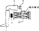
图1e为一个触觉指示装置的原理图,该装置包括带有一个并联运动学元件21(六脚机器人,工作升降平台(Stewartplattform))的力执行器。它的特征是具有六个线性驱动装置。通过六个驱动装置的长度变化,可以将末端受动器设定在任意的、解剖学上有意义的三维位置和方向上。末端受动器上安装一个六组元力—力矩—传感器,它将其测量信号传输到机器人控制装置和生物力学关节模拟器。在传感器上通过一个连接单元安装人造小腿,它使得操作人员实现交互式操作。FIG. 1 e is a schematic diagram of a tactile display device comprising a force actuator with a parallel kinematics element 21 (hexapod, working elevating platform (Stewartplattform)). It features six linear drives. The end effector can be set in any anatomically meaningful three-dimensional position and orientation by changing the length of the six driving devices. A six-component force-torque-sensor is installed on the end effector, which transmits its measurement signals to the robot control device and biomechanical joint simulator. The artificial lower leg is installed on the sensor through a connection unit, which enables the operator to realize interactive operation.
图1f为带有一个集成执行器的腿部单元的原理图。其中小腿包括两个单元,足22和腿,它们二者之间以关节连接,并由一个电动机主动驱动。一个电动机驱动的关节23包裹在塑料中,这样使得人造小腿和足具有符合解剖学的形状并可以运动。通过一种简单的控制实现足关节的运动。Figure 1f is a schematic of the leg unit with an integrated actuator. Wherein the shank includes two units, the
另外,在大腿的最远端的膝关节区域内集成安装一个扬声器24。仍然保持了大腿的符合解剖学的形状和硬度。在运动中出现的关节声响通过该扬声器给出,以使得操作人员可以得到一个真实的声响定位。In addition, a
图1g至图1m为膝关节模拟器的其他结构细节。对不同的实施例给出了清晰的显示,因此针对本领域技术人员不再重复描述。Figure 1g to Figure 1m are other structural details of the knee joint simulator. The different embodiments are clearly shown, so the description will not be repeated for those skilled in the art.
图2为一个脊椎关节模拟器,它在结构和功能上与图1a中的关节模拟器的原理相同。多个传感器—执行器单元通过一个弹性膜相互连接。椭圆形的末端受动器描述了虚拟患者的各个脊椎骨。皮肤通过弹性膜模拟。它可以覆盖脊椎骨之间的缝隙并使得人造皮肤表面手感光滑。通过执行器、传感器和控制装置模拟脊椎骨之间相互的作用。即当医生在一个脊椎上施加一个力并使其移动时,力和运动将被获取并进行进一步处理,使得相邻的脊椎表现为被动的跟随运动。Figure 2 is a spine joint simulator, which is the same in structure and function as the joint simulator in Figure 1a. Several sensor-actuator units are interconnected via an elastic membrane. The oval-shaped end effectors describe the individual vertebrae of the virtual patient. Skin is simulated by an elastic membrane. It can cover the gap between the vertebrae and make the artificial skin surface feel smooth. Simulate the interaction between vertebrae through actuators, sensors and controls. That is, when a doctor applies a force on one vertebra and causes it to move, the force and motion are captured and processed further so that the adjacent vertebrae appear to follow passively.
下一个实施例作为完整的根据本发明的技术指导而公开。为此对调节和控制理论作深入的讨论和详细的解释,如本领域技术人员应该采取的措施,可以为特定的关节建立关节模拟器。其中以膝关节模拟器为基础进行解释。The next embodiment is disclosed as a complete technical guide according to the present invention. To this end, an in-depth discussion and detailed explanation of the regulation and control theory, as a person skilled in the art should take, can establish a joint simulator for a specific joint. The explanation is based on a knee joint simulator.
在设计人造腿部单元时为实现符合解剖学的尺寸和硬度特征,用多种不同硬度的塑料层包裹一个模型骨骼(图3)。在用泡沫材料层包裹后,腿部骨骼可以实现一个真实病理上的突出的骨骼位置,例如腓骨或骨节的骨骼位置。皮肤表面和骨骼之间的身体部位的厚度很小,例如在胫骨,膝盖骨或骨节上通过粘贴一层薄塑料层(2至4mm厚,肖氏硬度A18至A25)进行模拟。在有肌肉的位置粘贴多层硬的单元聚乙烯层(10至20mm厚,肖氏硬度A20至A40),并进行很好的磨光,以得到符合解剖学的肌肉轮廓形状。然后覆盖上一层软的聚氨基甲酸乙酯发泡材料,以得到一个1至3mm厚度的具有真实手感的表面层。然后在整个腿上喷涂PUR塑料,作为弹性皮肤覆盖层。To achieve anatomical size and stiffness characteristics when designing an artificial leg unit, a model bone is wrapped with layers of plastic of varying stiffness (Fig. 3). After wrapping with a foam layer, the leg bones can achieve a realistic pathologically prominent bone position, such as the bone position of the fibula or condyle. Body parts with a small thickness between the skin surface and the bone, for example on the tibia, patella or condyle, are simulated by pasting a thin plastic layer (2 to 4 mm thick, Shore hardness A18 to A25). Multiple layers of hard unitary polyethylene layers (10 to 20mm thick, Shore hardness A20 to A40) are pasted on the muscles and polished well to obtain anatomically contoured shapes of the muscles. It is then covered with a layer of soft polyurethane foam to obtain a realistic surface layer with a thickness of 1 to 3 mm. PUR plastic is then sprayed over the entire leg as an elastic skin covering.
操作模式:Operating mode:
以下描述了不同的操作模式,以说明本发明的多种使用可能性。The different modes of operation are described below to illustrate the many possibilities of use of the invention.
1.交互式操作模式1. Interactive operation mode
在交互式操作模式中,操作者移动机器人,它与操作者相互作用。操作者触动小腿并使其在所希望的方向上运动。由此产生的力、力矩和运动被测量,并通过一个基于模型的控制装置进一步处理,使得小腿根据生物力学特征在所希望的方向上运动。In interactive operation mode, the operator moves the robot, which interacts with the operator. The operator touches the lower leg and moves it in the desired direction. The resulting forces, moments, and movements are measured and further processed by a model-based control device, which causes the lower leg to move in the desired direction according to the biomechanical characteristics.
2.主动操作模式2. Active operation mode
在主动操作模式中,机器人根据一个固定的、预先设定的轨迹运动。操作者由机器人引导在特定的关节测试中可靠地完成最佳的运动路径。同时可以测量操作者所施加的力并对其显示和评估。因为在这种模式下机器人指导操作者,所以该模式也称为指导模式。关节测试的轨迹可以从文献中查询或通过无触摸的运动测量方法确定。In the active mode of operation, the robot moves according to a fixed, preset trajectory. The operator is guided by the robot to reliably follow the optimal path of motion in a specific joint test. At the same time, the forces exerted by the operator can be measured, displayed and evaluated. Because in this mode the robot guides the operator, this mode is also referred to as the guidance mode. Trajectories for joint testing can be consulted in the literature or determined by non-touch kinematic methods.
3.静态操作模式3. Static operation mode
在某些使用中,膝关节模拟器也可以以简单的静态模式操作,可以不需要机器人的运动。当操作者在小腿上执行任意的练习动作时将出现力和力矩。该动作例如可以是触诊、人工外科或整形外科手术、对静止的腿的功能测试或对小腿敲击以唤起膝跳反射或跟腱反射。根据检测到的力和力矩的过程,可以使操作者在学习过程中掌握相应的知识。该过程可以在线或离线地与其他操作者的记录或教师的记录进行比较。另一方面,当力和力矩信号超过某一门限值时,该过程也可以用于引起某些结果。引起这些结果可以以主动或交互的方式进行。该功能原理随后将在膝跳反射的示例中详细说明。In some uses, the knee simulator can also be operated in a simple static mode, which may require no robot motion. Forces and moments occur when the operator performs any exercise on the lower leg. The action can be, for example, palpation, artificial or orthopedic surgery, a function test on a stationary leg or a tap on the calf to evoke the knee jerk or Achilles tendon reflex. According to the process of detected force and moment, the operator can master the corresponding knowledge during the learning process. The process can be compared with other operator's records or teacher's records online or offline. On the other hand, the process can also be used to cause certain effects when the force and torque signals exceed certain thresholds. Inducing these results can be done in an active or interactive manner. This functional principle will be explained later in the example of the knee jerk reflex.
图解显示:The diagram shows:
通过监示器可以对内部解剖单元,例如骨骼,肌腱,韧带和半月板实现可视化。监示器可以选择与光栅眼镜配合以立体模式显示。运动动画与触觉指示的运动同步,即关节模拟器的膝盖解剖模型。因此,操作者可以在运动过程中学习到躯体内部的健康的或患病的膝关节的解剖关系和生物力学关系。可视化基于切片和3D重建的CT图像或者MRT图像来实现。这将为解剖单元赋予很好的真实现象图。The monitor enables visualization of internal anatomical units such as bones, tendons, ligaments and menisci. The monitor can optionally be displayed in stereoscopic mode with lenticular glasses. The motion animation is synchronized with the motion of the haptic indications, i.e. the joint simulator's knee anatomical model. Therefore, the operator can learn the anatomical and biomechanical relationships of the healthy or diseased knee joint within the body during the movement. Visualization is based on slices and 3D reconstructed CT images or MRT images. This will give a nice picture of the real phenomenon for the anatomical unit.
在图形显示中,与运动同步的骨骼和软骨的长度变化,韧带和关节囊的曲线变化以及肌肉的变形都需要考虑。这些运动过程的可视化可通过所谓的“动态CT和MRT成像”实现。这里涉及到电影摄影技术,它不允许超过一个自由度的交互操作,因此不适用于VR领域(Dupuy等,1997;Witonski和Goraj 1999)。一种替代方案是基于模型的动画。其中,对所有组件的几何特征和粘度弹性特征,以及它们的机械配合进行建模。为实现近似实际的模拟,有限元计算和复杂的多体接触模型是必要的,这将使模拟技术上的开销大大提高。Changes in the length of bones and cartilage, changes in the curves of ligaments and joint capsules, and deformations in muscles that are synchronized with movement all need to be considered in the graphical display. Visualization of these movement processes is possible with so-called "dynamic CT and MRT imaging". Cinematography is involved here, which does not allow interactive manipulation of more than one degree of freedom and is therefore not applicable in the VR domain (Dupuy et al., 1997; Witonski and Goraj 1999). An alternative is model-based animation. In it, the geometrical and viscoelastic properties of all components, as well as their mechanical fit, are modeled. In order to realize the approximate actual simulation, finite element calculation and complex multi-body contact model are necessary, which will greatly increase the cost of simulation technology.
符合目的的是采用一种组合方法,其中使用了图像数据和解剖学模型观察。附件中包括几何数据,它由大量的离散关节角度位置重建得到,并进行内插和外插,保证对于任意的关节角度位置在每一个重要的自由度上都可以显示,也参见图4。此时内插和外插是由模型支持的,例如可考虑通过保持肌肉体积不变或者保持韧带长度恒定来实现。由于这样可实现相对较低的计算开销,故而在任意的运动方向上可以实现实时的平滑运动过程。It is expedient to use a combined method in which image data and anatomical model observations are used. The appendix includes geometric data, which is reconstructed from a large number of discrete joint angular positions, and interpolated and extrapolated to ensure that any joint angular position can be displayed in every important degree of freedom, see also Figure 4. In this case, the interpolation and extrapolation are supported by the model, for example, by keeping the muscle volume constant or the ligament length constant. Due to the relatively low computational cost achieved in this way, a real-time smooth motion process can be realized in any direction of motion.
声音指示:Sound indication:
通过声音指示装置可以再现膝关节运动中出现的声响。这些声响可能是被动的摩擦声响或咬合声响,这些声响由接触的关节表面形成,也可能是患者由于疼痛发出的声响,例如大声呼喊或喊叫。The sound that occurs during the movement of the knee joint can be reproduced by the sound indicator device. These sounds may be passive rubbing or occlusal sounds created by contacting joint surfaces, or they may be sounds made by the patient in response to pain, such as yelling or shouting.
根据本发明在多个被测者处记录不同的关节声响。声学输出理论上是测试所造成的疼痛的结果,它可以人工调节也可做出记录。所有的声响进行了妆类,存储成一个声音数据库。According to the invention, different joint sounds are recorded at multiple subjects. The acoustic output, which is theoretically a result of the pain induced by the test, can be manually adjusted and recorded. All the sounds are sorted and stored as a sound database.
为给出声音必须寻找模型,该模型使得声音的类型与引起该声响的损伤类型和表现出的膝部动力学相互之间形成关联,也可对照图5。在与医生对话之后,上述关联首先通过语言变量进行定性的描述。通过模糊逻辑方法可由语言说明推导出定量的关系。模糊逻辑模型通过两个选中的例子进行检测并在以下给出解释。To define the sound, a model must be found which correlates the type of sound with the type of injury causing the sound and the knee dynamics present, see also FIG. 5 . The above-mentioned associations were first described qualitatively through linguistic variables following a dialogue with the physician. Quantitative relationships can be deduced from verbal descriptions by means of fuzzy logic. The fuzzy logic model is examined with two selected examples and explained below.
在第一个示例中,在内部韧带损伤情况下建立损伤程度、冲压下的外翻/内翻力矩和所引起的疼痛程度之间的关联。图6给出了模糊系统的特征域,其中输出量“疼痛”(z轴)看作外翻/内翻力矩和韧带损伤程度的函数。在第二个示例中考虑半月板损伤。其中所造成的疼痛在建模中看作损伤程度、损伤位置、弯曲角度以及冲压下外翻力矩的函数。In a first example, in the case of an internal ligament injury, a correlation is established between the degree of injury, the valgus/varus moment under punching and the degree of pain caused. Figure 6 shows the characteristic domain of the fuzzy system, where the output "pain" (z-axis) is seen as a function of valgus/varus torque and ligament damage degree. Consider a meniscal injury in the second example. The resulting pain was modeled as a function of the degree of injury, location of the injury, angle of bend, and valgus moment under punching.
对膝关节模拟器的技术要求Technical Requirements for Knee Joint Simulators
膝关节模拟器所要满足的技术要求以要进行的临床功能测试和测试中出现的动力学特征为标准。The technical requirements to be fulfilled by the knee simulator are based on the clinical functional tests to be performed and the dynamic characteristics present during the tests.
膝关节的临床功能测试Clinical Functional Testing of the Knee
在这一段中建议对临床功能测试中不同的组和子组(Untergruppe)作概况性的了解,对比表1。In this paragraph an overview of the different groups and subgroups (Untergruppe) in clinical function tests is proposed, compare Table 1.
不同的测试用于测试关节的稳定性和在三个旋转自由度上的移动性。可以区分为弯曲/伸展测试、内/外旋转测试和内翻/外翻测试。该测试首先用于对囊韧带损伤的测试诊断。Different tests are used to test the joint's stability and mobility in three rotational degrees of freedom. A distinction can be made between flexion/extension testing, internal/external rotation testing, and varus/valgus testing. This test was first used for the test diagnosis of capsular ligament injury.
在抽屉试验中在平移自由度上进行运动。使得小腿在前面和后面以及侧面和中间的方向相对于大腿移动。Movement is performed in translational degrees of freedom in the drawer test. Causes the calf to move relative to the thigh in front and rear and side and medial directions.
旋转—移动—测试在多个自由度上进行,同时在不同的方向上施加力。Rotation-movement-tests are performed in multiple degrees of freedom while applying forces in different directions.
另一组是旋转测试或折回测试,其中机械重力确定了所有的旋转自由度。Another group is the rotation test or foldback test, where mechanical gravity determines all rotational degrees of freedom.
膝跳反射测试用于确定电动机和传感器的故障。The knee jerk test is used to identify motor and sensor malfunctions.
为更好的理解下述实施例,可选择进行上述测试。For a better understanding of the following examples, the above tests can be optionally performed.
总共可确定86种测试,其中在进行膝部诊断时不必掌握所有测试,因为许多测试在运动过程中是不重要的,故由此识别出的损伤是不同的。为清楚的说明,在表1中给出了根据本发明的膝关节模拟器的通用的使用情况。A total of 86 tests could be determined, of which it is not necessary to have all the tests available for the knee diagnosis, since many tests are not important during the movement and the injuries identified thereby are different. For the sake of clarity, general use cases for the knee joint simulator according to the invention are given in Table 1.
表1:现有的可执行膝部功能测试一览表
N:不能进行或仅在一定条件下可进行N: Not available or available only under certain conditions
A:仅在锁定大腿时可以进行(见4.37节)A: Can only be performed when the thigh is locked (see Section 4.37)
B:仅在大腿被动移动时可以进行(见4.37节)B: Can only be performed with passive thigh movement (see Section 4.37)
A+B:在任意位置均可以进行A+B: Can be done at any position
括号中的值给出了可转换的测试个数Values in parentheses give the number of tests that can be converted
使用膝关节模拟器可进行的功能测试Functional tests possible with the knee simulator
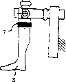
主要目的是对尽可能多的功能测试进行模拟。在以膝关节模拟器进行测试模拟时,主要受到机器人的有限多个主动自由度数的限制。由于使用的机器人只有6个自由度,但是一条腿包括三个部分,即大腿、小腿和足,在理论上需要18个自由度来描述。可以减少上述自由度的个数,例如冻结住那些对应的运动幅度很小的自由度和对进行膝部测试意义不大的自由度。由于在此处所建议的应用中足部的运动意义不重要,并且可以认为髋关节不作平移运动,则系统的自由度可以减少到9个。还可以通过对腿的运动自由度的附加限制进一步缩减少自由度的数目。部分功能测试可以转化为以一个简化的试验配置进行,其中大腿不做运动,即将大腿在空间上固定,但是保证它可以调节(对照图7A)。因此小腿相对于大腿只有6个自由度,小腿可旋转运动也可平移运动。当解除锁定使得大腿在两端铰接时(对照图7B),则可对大多数常见膝部测试进行模拟。此外可冻结膝关节6个自由度中的3个。最好冻结3个平移自由度;腿主要用于描述宏观运动过程。The main purpose is to simulate as many functional tests as possible. When the test simulation is carried out with the knee joint simulator, it is mainly limited by the limited number of active degrees of freedom of the robot. Since the robot used has only 6 degrees of freedom, but a leg includes three parts, namely thigh, calf and foot, it needs 18 degrees of freedom to describe in theory. The number of the above-mentioned degrees of freedom can be reduced, for example, those degrees of freedom corresponding to a small range of motion and those degrees of freedom that are of little significance to the knee test are frozen. Since the motion of the foot is not significant in the application proposed here, and the hip joint can be considered to have no translational motion, the degrees of freedom of the system can be reduced to nine. The number of degrees of freedom can also be further reduced by additional constraints on the degrees of freedom of movement of the legs. Part of the functional test can be converted to a simplified test configuration in which the thigh does not move, ie the thigh is spatially immobilized but allowed to adjust (cf. Fig. 7A). Therefore, the calf has only 6 degrees of freedom relative to the thigh, and the calf can rotate and move in translation. When unlocking allows the thigh to articulate at both ends (cf. Figure 7B), then most common knee tests can be simulated. In addition, 3 of the 6 degrees of freedom of the knee joint can be frozen. It is best to freeze 3 translational degrees of freedom; legs are mainly used to describe macroscopic motion processes.
除了将试验结构的自由度缩减为6个或者更少之外,作为替代也可以引入更多的主动自由度,以实现以9个或更多的自由度,更接近真实的人腿的再现。例如可以使用一个第二执行器来实现,该执行器与人造大腿相连接。In addition to reducing the degrees of freedom of the test structure to 6 or less, more active degrees of freedom can be introduced instead to achieve a closer reproduction of the real human leg with 9 or more degrees of freedom. This can be done, for example, using a second actuator which is connected to the artificial thigh.
原理上功能测试可以在主动操作模式下进行也可以在交互式操作模式下进行。但是在使用交互式操作模式时需要注意,从大腿传递到小腿的力和力矩很小,可以忽略,或者是已知的,可以再现。只有这样才能唯一地确定操作人员和腿之间的力和力矩,这保证了无歧义的控制和对生物力学特征正确的描述。在大腿锁定的配置下不存在问题,因为大腿和小腿不接触。在大腿可移动的配置下,只出现很小的力和力矩,这种力和力矩是已知的,可以做出补偿。In principle the function test can be carried out in active operation mode as well as in interactive operation mode. However, when using the interactive operation mode, it should be noted that the forces and moments transmitted from the upper leg to the lower leg are small and can be ignored, or are known and can be reproduced. Only in this way can the forces and moments between the operator and the legs be uniquely determined, which guarantees unambiguous control and a correct description of the biomechanical characteristics. In the thigh-locked configuration there is no problem because the thigh and calf do not touch. In the movable thigh configuration, only small forces and moments occur, which are known and can be compensated for.
功能测试的动力学特征Kinetic Characterization of Functional Tests
操作者可以对膝的位置和角度的改变以接近毫米和几度的精确度进行估计。更高的分辨率对于关节损伤的临床测试是没有意义的,因为只有超过3毫米的偏差才被认为是病理学现象。The operator can estimate changes in knee position and angle with an accuracy close to millimeters and a few degrees. A higher resolution is meaningless for clinical testing of joint injuries, since only deviations of more than 3 mm are considered pathological.
在测试腿时,每次测试的速度是变化的。例如在诊断半月板损伤中,进行麦氏试验(回旋挤压试验)时运动速度很快。膝关节的速度达到约为130°/秒。When testing the legs, the speed is varied for each test. For example, in the diagnosis of meniscus injury, the movement speed is very fast when performing the Maxwell test (rotary squeeze test). The velocity of the knee joint reaches approximately 130°/sec.
测试中出现的检验员的力的大小也是差异很大的。当进行测试的医生在执行一项测试时需要拿住整条腿,即足、小腿和大腿必须承受重力作用时,则使用的力就大。典型的数值是100至150N。在水平方向上进行抽屉试验中也可能出现近似大小的力。此时作用的旋转力矩自然取决于相应的力臂。在抽屉试验中,当典型的力臂为10cm时,作用在膝关节上的力矩近似于10至15Nm。The magnitude of the examiner's force that occurs during testing also varies widely. The force used is high when the doctor performing a test needs to hold the entire leg while performing a test, ie the foot, calf and thigh must bear the force of gravity. Typical values are 100 to 150N. Forces of similar magnitude may also occur in the drawer test in the horizontal direction. The rotational torque acting here naturally depends on the corresponding moment arm. In the drawer test, when the typical moment arm is 10 cm, the moment acting on the knee joint is approximately 10 to 15 Nm.
人体膝关节在某些运动方向上具有很大的刚度,对此机器人必须尽可能的超量实现,以保证机器人的伸缩不至于干扰到末端受动器的位置和方向。The human knee joint has great stiffness in certain motion directions, and the robot must realize this as much as possible to ensure that the expansion and contraction of the robot will not interfere with the position and direction of the end effector.
除功能测试中出现的具有特征的运动学和动力学的值,在设计执行器时也要考虑膝关节的动力学行为。由于此原因,应以前面所介绍的生物力学模型为基础研究膝关节的系统动力学。在对多个选中的关节角度位置进行线性化后,确定特定运动方向上的固有频率。在弯曲/伸展和外翻/内翻方向上,固有频率在1.5Hz以下。在向前/向后方向上由于刚度高,固有频率的值明显较大,为11-19Hz。In addition to the characteristic kinematic and dynamic values that emerge from the functional tests, the dynamic behavior of the knee joint is also taken into account when designing the actuator. For this reason, the system dynamics of the knee joint should be studied on the basis of the biomechanical models presented earlier. After linearizing a number of selected joint angular positions, the natural frequencies in a particular direction of motion are determined. In the flexion/extension and valgus/varus directions, the natural frequency is below 1.5 Hz. Due to the high stiffness in the forward/backward direction, the natural frequency has a significantly larger value of 11-19 Hz.
表2:技术要求的可实现性
*该技术数据描述了最弱关节或各种不利状态下的最大值。因此也经常作为可实现的最高值。 * This technical data describes the maximum value for the weakest joint or various unfavorable conditions. It is therefore often used as the highest achievable value.
#最低值只适用于初始控制#minimum value only applies to initial control
可由执行器描述的动力学特征:Dynamic characteristics that can be described by actuators:
接近实际的模拟的前提条件是所述的动力学膝部特征也可由执行器描述。膝部特征因此决定了技术要求,执行器必须能满足该技术要求。执行器对技术要求符合的越好,所描述的膝部特征越接近真实。A prerequisite for a close-to-real simulation is that the dynamic knee behavior described can also be described by the actuator. The knee characteristics thus determine the technical requirements, which the actuator must be able to meet. The better the actuator conforms to the specification, the closer the described knee characteristics will be to reality.
为实现触觉指示选择了Stubli RX90作执行器。由于具有很高的位置精度和可达283°/秒(在最慢的关节中)的高速度,它可以很好地满足运动学要求。由机器人产生的力和力矩也在要求的值域范围内(见表2)。所选择的JR3力—力矩传感器在平移自由度情况下的量程为±200N,在旋转自由度情况下的量程为±20Nm,可以满足测量任务的要求。机器人的刚度很高。在平移自由度情况下,机器人的刚度行为可以通过试验测定。在末端受动器区域内的刚度根据偏转方向不同在150-200N/mm之间,与人体膝关节的刚度处于同一个数量级。Stubli RX90 was selected as the actuator for tactile indication. It satisfies kinematic requirements well thanks to its high positional accuracy and high speeds of up to 283°/s (in the slowest joint). The forces and moments generated by the robot are also within the required range of values (see Table 2). The selected JR3 force-torque sensor has a measuring range of ±200N in the case of the translational degree of freedom, and a measuring range of ±20Nm in the case of the rotating degree of freedom, which can meet the requirements of the measurement task. The stiffness of the robot is very high. In the case of translational degrees of freedom, the stiffness behavior of the robot can be determined experimentally. The stiffness in the area of the end effector is between 150-200N/mm according to the deflection direction, which is in the same order of magnitude as the stiffness of the human knee joint.
在控制技术问题上,建议采样率是所描述的带宽的15至50倍。因此在本使用情况下采样率为750-2500Hz。对于其他的采样触觉指示装置,建议采样率也是类似的一个高值,至少为1kHz。机器人的原始控制计算机不能满足该要求,因为它所需的循环时间很长,为16ms,对应的采样率为62.5Hz。使用一个新构造的基于PC机的控制装置可以将采样率提高到4kHz。In matters of control technology, a sampling rate of 15 to 50 times the bandwidth described is recommended. So in this use case the sampling rate is 750-2500Hz. For other sampling tactile pointing devices, the recommended sampling rate is a similarly high value of at least 1kHz. The robot's original control computer could not meet this requirement because of the high cycle time it required, 16ms, corresponding to a sampling rate of 62.5Hz. The sampling rate can be increased to 4kHz using a newly constructed PC-based control unit.
主动和交互式操作模式:控制策略Active and Interactive Modes of Operation: Control Strategies
触觉指示装置控制Tactile Pointer Control
基本上所有对机械执行器进行力控制的问题(Colgate和Hogan1989;Eppinger和Seering 1987;Townsend和Salisbury 1989)都出现在膝关节模拟器(触觉指示器)上,其中本发明还附加地将与执行器(机器人)相互作用的人包括在控制循环中。这提出了一个控制技术上的挑战,因为机械特征可能是剧烈变化的,而且操作者的行为通常是无法预见的。本领域技术人员可以从以下公开文献中得到有关研究此类人机交互系统控制和稳定性的启示:Kazerooni和Her1994;Brown和Colgate 1997;Clover 1999;Hannaford和Adams1999;Carignan和Cleary 2000。Essentially all problems of force control of mechanical actuators (Colgate and Hogan 1989; Eppinger and Seering 1987; Townsend and Salisbury 1989) arise on knee simulators (tactile indicators), where the present invention additionally integrates Humans interacting with machines (robots) are included in the control loop. This presents a control technology challenge, as mechanical characteristics may vary drastically and operator behavior is often unpredictable. Those skilled in the art can get enlightenment for studying the control and stability of such human-computer interaction systems from the following publications: Kazerooni and Her1994; Brown and Colgate 1997; Clover 1999; Hannaford and Adams1999; Carignan and Cleary 2000.
一个机械系统的功能可以通过力f(t)和运动x(t)之间的关系来描述。如果将运动作为外加量,则可将该关系定义为机械阻抗Z。例如,如果一个物体具有很高的机械阻抗,则意味着当使该物体承受弹力、阻尼力和/或其所承载的阻力而运动时,需要施加一个很大的力。相反,如果选取力作为输入量,则可定义机械导纳Y:The function of a mechanical system can be described by the relationship between force f(t) and motion x(t). If motion is an applied quantity, this relationship can be defined as mechanical impedance Z. For example, if an object has high mechanical impedance, it means that a large force needs to be applied to move the object against spring forces, damping forces, and/or the resistance it carries. Conversely, if force is chosen as the input quantity, the mechanical admittance Y can be defined:
f(t)=Z(x(t)),x(t)=Y(f(t))f(t)=Z(x(t)), x(t)=Y(f(t))
对触觉交互式操作可通过导纳和阻抗结构描述。在图8和图9中给出一个网络图描述,其中虚导纳Yv或阻抗ZV通过触觉指示器H,这里表现为二端口网络,与操作者B产生关系。在导纳结构中借助于一个虚导纳Yv,由测量得到的、由操作者预先给定的力(fv=fb)确定相应的位移xV(图8)。触觉指示器的任务是尽可能准确地将该位移xV向操作者展示。操作者通过相互作用的躯体部分(例如他的手或臂)的阻抗ZB,以一个测量出的力应答fB对标记的位移xB做出反应。The interactive manipulation of haptics can be described by the structure of admittance and impedance. In Fig. 8 and Fig. 9 a diagrammatic description of a network is given in which the imaginary admittance Yv or impedance ZV is brought into relation to the operator B through a tactile indicator H, here represented as a two-port network. With the aid of a virtual admittance Yv in the admittance structure, the corresponding displacement x V is determined from the measured force (fv=fb) specified by the operator ( FIG. 8 ). The task of the tactile indicator is to present this displacement x V to the operator as accurately as possible. The operator responds to the marked displacement x B with a measured force response f B via the impedance Z B of the interacting body part (eg his hand or arm).
相应地,阻抗结构(图9)中的关系相反。作为上述触觉指示器的输入和输出关系的结果,触觉指示器在导纳结构情况下为位置命令方式,在阻抗结构下为力命令方式。Correspondingly, the relationship is reversed in the impedance structure (FIG. 9). As a result of the input and output relationships described above for tactile indicators, tactile indicators are position commanding in the case of admittance structures and force commanding in resistive structures.
触觉指示器的目的是使操作者可以同时得到力和运动的印象,如同他们在待描述的导纳或阻抗上所应该经历的。在理想情况下(透过性(Transparenz))有:The purpose of the tactile indicator is to allow the operator to simultaneously get the impression of force and motion as they would experience on the admittance or impedance to be described. Ideally (Transparenz) there are:
xB=xV,fB=fV x B =x V , f B =f V
但是由于每个触觉指示器由于其质量和摩擦的关系具有自身的动力学特性,必须在触觉指示器上尝试着进行相应的力和位置的控制,以使得在非理想的边界条件下实现透过性。困难的是所有的三个部分,即待描述的虚导纳和阻抗,触觉指示器和操作者通常具有非线性特征。However, since each tactile indicator has its own dynamic characteristics due to the relationship between its mass and friction, it is necessary to try to control the corresponding force and position on the tactile indicator, so that the penetration can be realized under non-ideal boundary conditions. sex. The difficulty is that all three parts, virtual admittance and impedance to be described, tactile indicator and operator usually have non-linear characteristics.
这两种控制结构的前提条件是虚导纳或阻抗可明确地描述。当确定出阻抗Zv的值很大或具有机械强制条件时(例如虚拟壁垒,即Zv→∞或Yv=0),使用导纳控制是有利的。在此情况下,由于待描述的导纳的低通特性,可以大大减弱测得的力信号的动态特性,使得所需的轨道控制只需要跟随小的位置变化。因此传感器噪声(力传感器)对于轨道控制的影响很小。相反的,阻抗控制主要用于描述小阻抗Zv,因此用于自由运动情况(Zv=0)。A prerequisite for both control structures is that the imaginary admittance or impedance can be unambiguously described. The use of admittance control is advantageous when it is determined that the value of the impedance Zv is large or has mechanically enforced conditions (eg virtual barriers, ie Zv→∞ or Yv=0). In this case, due to the low-pass nature of the admittance to be described, the dynamics of the measured force signal can be greatly attenuated such that the required trajectory control only needs to follow small position changes. Therefore sensor noise (force sensor) has little effect on track control. In contrast, impedance control is mainly used to describe small impedances Zv, and thus for free motion situations (Zv=0).
本领域技术人员可以根据所述实施例得知,触觉指示器的机械带宽不仅由所使用的技术元件的特征决定,例如驱动设备的功率或运动部件的重量等,而且也受到操作人员阻抗的影响。这主要取决于如何与触觉指示器相接触以及操作者躯体的哪一部位与触觉指示装置相接触,操作者相应的部分具有哪些被动的人体测量学特征,以及操作者操作的行为如何,即他是以“令人有好感”的被动方式、“攻击性”的主动方式、还是强硬”的刚性方式进行操作的。A person skilled in the art will know from the described embodiments that the mechanical bandwidth of the tactile indicator is determined not only by the characteristics of the technical components used, such as the power of the drive equipment or the weight of the moving parts, etc., but also by the impedance of the operator . This mainly depends on how and which part of the operator's body is in contact with the tactile indicator device, what passive anthropometric characteristics the corresponding part of the operator has, and how the operator operates, i.e. he Do you operate in a "favorable" passive way, an "aggressive" active way, or a tough" rigid way.
主动操作模式(指导模式)Active Operation Mode (Guided Mode)
在主动操作模式下,膝关节模拟器的解剖模型遵循一个预先给定的额定轨迹运动,该运动轨迹符合典型的关节功能测试时的运动过程。测量到的膝关节运动参数以离线方式处理,并生成经典轨道控制额定位置曲线qK,soll(t),如图10所示。在触动腿部时由操作者向机器人施加的力作为轨道控制的干扰量进行补偿。In the active operating mode, the anatomical model of the knee simulator follows a predetermined nominal trajectory, which corresponds to the movement process of a typical joint function test. The measured knee joint motion parameters are processed offline, and a classical track control nominal position curve q K, soll (t) is generated, as shown in Fig. 10. The force applied by the operator to the robot when touching the legs is compensated as a disturbance to the orbital control.
交互式操作模式interactive mode of operation
在此操作模式下,操作者可以影响机器人的运动,也可以预先规定机器人的运动。其中机器人作为触觉指示器来工作,它的任务是描述虚拟对象的机械特征。基于两种不同的结构,导纳结构和阻抗结构,进行控制技术转换。In this mode of operation, the operator can influence the movement of the robot, as well as predetermine the movement of the robot. Where the robot works as a tactile pointer, its task is to describe the mechanical characteristics of the virtual object. Based on two different structures, the admittance structure and the impedance structure, the control technology conversion is carried out.
导纳控制源于轨道控制结构(图10)的扩展。在操作者和机器人之间作用的负载 τ B用力—力矩传感器测量。在一个生物力学模型中,计算由实际负载情况 τ B所产生的膝部运动,并将计算结果输送到轨道控制器中作为额定运动qK,soll(图11)。轨道控制器最终产生相应的执行器力矩 τ A,用于驱动机器人。为改善控制关系,可将测得的操作者的力考虑为轨道控制算法中的干扰量输入(图11,虚线箭头)。具有大量的不同参数组可供选用,以实现对不同的健康或患病的膝关节特征的模拟。Admittance control is derived from the extension of the track control structure (Fig. 10). The load τ B acting between the operator and the robot is measured with a force-torque sensor. In a biomechanical model, the knee motion resulting from the actual load situation τ B is calculated and fed to the track controller as a setpoint motion q K, soll (Fig. 11). The track controller finally generates the corresponding actuator torque τ A , which is used to drive the robot. To improve the control relationship, the measured operator force can be considered as a disturbance input in the trajectory control algorithm (Fig. 11, dashed arrow). A large number of different parameter sets are available to simulate different healthy or diseased knee characteristics.
膝关节的生物力学模型确定了运动方程:A biomechanical model of the knee joint determines the equations of motion:
该方程描述了操作者触动小腿所产生的膝部运动,其中的关系将在下文中详细解释。为描述导纳需对该运动方程的运动量 q K求解。为在控制结构中正确连接膝关节模型,必须在笛卡儿空间和膝关节系统及机器人关节空间之间进行坐标变换。由此得到广义膝部负载Q B,它是由操作者力和操作者力矩 τ B从笛卡儿空间变换到膝关节系统而得到的。在运动方程中计算出的膝部坐标 q K将作为 q K,soll引入到轨道控制器中,在轨道控制器中它最终变换到机器人关节空间中。This equation describes the knee motion produced by the operator touching the lower leg, the relationship of which will be explained in detail below. In order to describe the admittance, it is necessary to solve the motion quantity q K of the equation of motion. In order to correctly link the knee joint model in the control structure, a coordinate transformation must be performed between the Cartesian space and the joint space of the knee joint system and the robot. Thus, the generalized knee load Q B is obtained, which is obtained by transforming the operator force and operator moment τ B from the Cartesian space to the knee joint system. The knee coordinate q K calculated in the equation of motion will be introduced as q K, soll in the orbit controller, where it is finally transformed into the robot joint space.
作为替换,也可以采用阻抗控制,它与给出位置命令的导纳控制不同,特征是给出力命令。阻抗控制的原理是由测量得到的运动信号或角度信号计算出作为基础的操作者力和操作者力矩 τ B,soll,并将其提供给一个力控制算法(图12)。生物力学运动方程必须做出相应的变换。膝关节的速度和加速度可通过对测量到的并变换到膝关节系统中的角度信号的数字求导方法得到。如果在该角度信号中含有很高的噪声成分,该值也可以通过陀螺仪或加速度计传感器得到。力控制算法的作用是对计算到的机器人和操作者之间的相互作用力以尽可能小的误差实现转换。As an alternative, impedance control can also be used, which, in contrast to admittance control, which gives position commands, is characterized by force commands. The principle of impedance control is to calculate the basic operator force and operator moment τ B, soll from the measured motion signal or angle signal, and provide it to a force control algorithm (Fig. 12). The biomechanical equations of motion must be transformed accordingly. The velocity and acceleration of the knee joint can be obtained by numerically deriving the angle signal measured and transformed into the knee joint system. This value can also be obtained by a gyroscope or accelerometer sensor if there is a high noise component in the angle signal. The role of the force control algorithm is to transform the calculated interaction forces between the robot and the operator with as little error as possible.
如同以上以阐明的情况,当确定出很大的阻抗,例如机械强制条件的形式,则导纳控制是有利的。相反的,阻抗控制主要用于描述小阻抗,例如自由运动的形式。由于在对躯体关节运动进行模拟时阻抗不可能为零,而且在关节角度范围边缘甚至可能取一个很高的值,则此处介绍的导纳控制的使用方式是有利的。As stated above, admittance control is advantageous when large impedances are determined, for example in the form of mechanically imposed conditions. In contrast, impedance control is mainly used to describe small impedances, such as free-moving forms. Since the impedance cannot be zero when simulating body joint movements, and may even take on a very high value at the edges of the joint angle range, the use of admittance control as presented here is advantageous.
以下以膝跳反射的例子描述静态操作模式:The static mode of operation is described below with the knee jerk example:
通过敲击膝盘下面的膝腱可以引起膝跳反射。其中在膝腱中产生拉力,用于伸张大腿肌肉并由此产生腿部伸展。自由悬垂的小腿的运动程度用于判断神经功能,一方面取决于现有的疾病和各个刺激波,另一方面取决于例如由反射锤施加的敲击力的大小和位置。The knee jerk reflex can be induced by tapping the tendon beneath the knee plate. In this case, tension is generated in the knee tendon, which serves to stretch the thigh muscles and thereby create an extension of the leg. The degree of movement of the freely hanging lower leg is used to assess the neurological function and depends on the one hand on the existing disease and the respective stimulus wave and on the other hand on the magnitude and location of the percussion force exerted, for example by a reflex hammer.
以此处介绍的膝关节模拟器也可以描述虚拟膝跳反射。为此需要验证,以力—力矩传感器测量到的接触力是否满足可激起膝跳反射的必需条件。只有在满足这一条件时,在55ms的暂短等待时间之后,将产生一个短时的、典型反射的伸展力矩,其值为5Nm,使得小腿从一个静止的位置上开始转动。只要操作者没有通过接触对小腿产生影响,则在此之后小腿作静止位置附近的阻尼振动。为激起膝跳反射,接触力的值 F和它的变化率必须超过最小值,它们分别是:The virtual knee jerk reflex can also be described with the knee simulator presented here. To this end, it is necessary to verify whether the contact force measured by the force-torque sensor meets the necessary conditions to arouse the knee jerk reflex. Only when this condition is fulfilled, after a short waiting time of 55 ms, a short, typically reflexive extension moment of 5 Nm will be generated, causing the calf to rotate from a resting position. As long as the operator does not influence the lower leg through contact, the lower leg then acts as a damped vibration in the vicinity of the rest position. To arouse the knee jerk reflex, the value of the contact force F and its rate of change must exceed minimum values, which are:
| F|>10N且d| F|/dt>200N/s| F |>10N and d| F |/dt>200N/s
另外必须保证接触点在膝腱附近。为此必须使得接触角α、以及接触点和膝部中心之间的间距| B|满足:In addition, it must be ensured that the contact point is near the knee tendon. To do this, the contact angle α, and the distance | B | between the contact point and the center of the knee must satisfy:
|α|<20°且0.02m<| B|<0.05m|α|<20° and 0.02m<| B |<0.05m
测试的结果以图形的形式显示,或者以人造小腿的运动形式显示。对于最新的版本,可以自然地从静止模式切换到主动操作模式或者交互式操作模式。The results of the tests are displayed graphically or in the form of movement of the artificial lower leg. With the latest version, it is possible to switch naturally from stationary mode to active operation mode or interactive operation mode.
假设反射锤的力传递是瞬时实现的,则精确的击点点可以唯一地由力—力矩传感器给出的反应负载计算出。特别需要提及的是在解剖模型的击中点范围内不能设置力传感器或压力传感器。Assuming that the force transmission of the reflex hammer is instantaneous, the exact point of impact can be uniquely calculated from the reaction load given by the force-torque sensor. In particular, it should be mentioned that no force or pressure sensors can be placed within the range of the impact point of the anatomical model.
图13显示,测量得到的力—力矩对 Fs和 Ms理论上可由腿部不同的负载情况实现。对于每一种情况满足以下静力学方程Figure 13 shows that the measured force-moment pairs F s and M s can theoretically be realized by different loading conditions of the legs. For each case the following static equations are satisfied
Fs= F且 Ms= M+ r× F F s = F and M s = M + r × F
其中 r和 F为未知的作用负载。向量 r代表寻找到的在传感器坐标系中的力传递位置,原点为S。在使用尖形反射锤时可假设负载力矩自由传递,即 M=0。则:Where r and F are unknown applied loads. The vector r represents the force transmission position found in the sensor coordinate system, and the origin is S. When using a pointed reflex hammer, it can be assumed that the load moment is freely transmitted, ie M =0. but:
其中向量 Fs和 Ms的分量是已知的。由此得到方程组:where the components of the vectors F s and M s are known. This leads to the system of equations:
其中未知量为 r=(rx,ry,rz)T。当试图求解 r时,可以确定该方程组欠定,因为它的行列式始终为0:The unknown quantity is r = (r x , ry , r z ) T . When trying to solve for r , this system of equations can be determined to be underdetermined because its determinant is always 0:
这明显表明,力传递的位置在空间中是无法准确确定的。相反的,只有被考虑的力 F的作用线是可以确定的。该作用线位于E平面内,而E平面垂直于 Ms,其中S∈E,并可以作为参数方程This clearly shows that the location of force transmission cannot be precisely determined in space. Instead, only the line of action of the considered force F can be determined. This line of action lies in the E plane, which is perpendicular to M s, where S ∈ E, and can be given as the parametric equation
gs(λ)≡ r *+λ F= r *+λ F s g s (λ)≡ r * +λ F = r * +λ F s
在传感器坐标系中描述。其中 r *为一个在原点S和作用线之间的任意向量,例如:Described in sensor coordinate system. where r * is an arbitrary vector between the origin S and the line of action, for example:
由于被接触对象(即小腿)的表面是已知的,最终可以由力作用线和表面之间的切点确定力传递的点。反射锤的击中点就是力对准躯体的切点。Since the surface of the contacted object (ie, the lower leg) is known, the point of force transmission can be finally determined by the point of tangency between the force action line and the surface. The point of impact of the reflex hammer is the point of tangency where the force is aimed at the body.
为实现以膝关节模拟器对膝跳反射进行模拟,不需要分析确定接触点坐标。只需要知道是否打击在正确的位置上就可以了。为此需要检验,是否测量到的反应负载位于明确的、根据经验得到的值域范围内,它代表是否命中”。简化是可靠的,因为由以上解释可知,在反应负载与命中点之间可以建立唯一的对应关系。由上述可知,前提条件是一个瞬时的、单方向的力传递,而且小腿仅穿过力作用线的一个点。In order to simulate the knee jerk reflex with the knee simulator, it is not necessary to analyze and determine the contact point coordinates. Just need to know if the hit is in the right place. For this it is necessary to check whether the measured reaction load lies within a well-defined, empirically obtained range of values, which represents a hit". The simplification is reliable, since it follows from the above explanation that the relationship between the reaction load and the hit point can be Establish a unique corresponding relationship. From the above, we can see that the precondition is an instantaneous, unidirectional force transmission, and the lower leg only passes through one point of the force action line.
实现方式Method to realize
轨道控制器track controller
在通常的机器人中,进行轨道控制时带有一个所谓的“计算转矩”作为附件支持。为使得触觉指示器的不希望出现的动力学特征最小,需要将当前机器人的位置和运动所必须的电动机转矩通过一个在项目框架内识别的、动态机器人模型进行线性化。由于模型简化/不精确性以及干扰造成的剩余动力最终由PC控制机进行补偿。In conventional robots, orbital control is performed with a so-called "calculated torque" as attachment support. In order to minimize the undesired dynamics of the tactile indicator, the motor torques necessary for the current position and motion of the robot are linearized by a dynamic robot model identified within the framework of the project. The residual power due to model simplification/imprecision and disturbances is finally compensated by the PC control machine.
机器人模型考虑了关节摩擦和质量特征。机器人参数(质量、质重位置、摩擦系数)通过单个关节的频响特征测量来识别。尽管首先忽略了质量惯性矩的偏差以及机器人的科氏力效应,该简化模型已经可以得到令人满意的控制性能。The robot model takes joint friction and mass characteristics into account. Robot parameters (mass, mass position, coefficient of friction) are identified through frequency response characteristic measurements of individual joints. Although the deviation of the mass moment of inertia and the Coriolis force effect of the robot are ignored at first, the simplified model can already obtain satisfactory control performance.
基于PC机的控制PC-based control
触觉指示器通过六轴的Stubli工业机器人RX90进行验证。该机器人的原始控制计算机需要相对长的循环时间,该时间大于16ms。为实现触觉指示器的稳定运行,以及无干扰且更接近现实的对生物力学关节特征的描述,需要实时条件下的高达kHz范围内的采样率以及很高的计算效率,以实现基于模型的阻抗控制方法。由于此原因,并行地设置一个基于PC机的控制装置。通过一个转换开关,可以在PC机上实现角度位置传感器、力/力矩传感器以及用于Stubli计算机的关节放大器模拟信号的切换,该计算机上通过一个相应的PCI卡检测和输出信号。通过将关节放大器设置为电流控制,可以在PC机上实现上述的基于关节力矩接口的控制。由于PC机的计算效率高得多,可以将采样时间缩短到250μs,与原来的结构相比可以明显改善控制效果。这种方式的优点是可以使得所有原始部件,例如关节放大器、制动器安全电路、应急保持电路以及电源保持不变,可以继续使用。The tactile indicator is verified with a six-axis Stubli industrial robot RX90. The robot's original control computer required a relatively long cycle time, greater than 16ms. Achieving a stable operation of the tactile indicator and a disturbance-free and closer to reality description of the biomechanical joint characteristics requires a high sampling rate in the kHz range under real-time conditions and a high computational efficiency for model-based impedance Control Method. For this reason, a PC-based control is provided in parallel. Via a changeover switch it is possible to switch between the angular position sensor, the force/torque sensor and the analog signal of the joint amplifier for the Stubli computer on the PC, which detects and outputs the signal via a corresponding PCI card. By setting the joint amplifier as current control, the above-mentioned control based on the joint torque interface can be realized on the PC. Because the calculation efficiency of the PC is much higher, the sampling time can be shortened to 250μs, which can obviously improve the control effect compared with the original structure. The advantage of this method is that all original components, such as joint amplifiers, brake safety circuits, emergency holding circuits and power supplies, can remain unchanged and can continue to be used.
膝关节的生物力学模型Biomechanical model of the knee joint
小腿的运动动力学Movement Dynamics of the Calf
由操作者输入的接触力 F使得被接触的对象产生运动。小腿的运动通过以下运动方程描述:The contact force F input by the operator causes motion of the contacted object. The motion of the lower leg is described by the following equations of motion:
其中 q K为广义膝关节坐标, q k=(xant,xmed,xprox,flex,val,arot)T,它描述了小腿的空间位置和空间方向。其中,xant,xmed,xprox为前侧、内侧和近侧三个方向上的平移,flex,val,arot为膝弯曲方向、外翻方向和外旋方向上的转角(图14)。M为小腿与足的惯性矩阵。G描述了出现了重力力矩。 D和 E分别描述了膝关节中的阻尼力矩和弹性力矩。 Q B是广义负载。在运动方程中没有考虑主动肌肉力的影响。因为这里描述的是一个单摆结构,因此不出现科氏力。该运动方程通过隐式欧拉积分方法求解。Where q K is the generalized knee joint coordinates, q k = (x ant , x med , x prox , flex , val , arot ) T , which describes the spatial position and spatial direction of the lower leg. Among them, x ant , x med , and x prox are translations in the three directions of anterior, medial, and proximal, and flex , val , arot are the rotation angles in the direction of knee flexion, valgus, and external rotation (Fig. 14). M is the inertia matrix of the calf and foot. G describes the emergence of a gravitational moment. D and E describe the damping and elastic moments in the knee joint, respectively. Q B is the generalized load. The effect of active muscle force is not considered in the equation of motion. Since what is described here is a simple pendulum structure, there is no Coriolis force. The equations of motion are solved by the implicit Euler integration method.
由操作者施加到膝关节上的力 F体现在运动方程中的广义负载Q B=(Fant, Fmed,Fprox,Mflex,Mval,Marot)T项中。 Q B的分量可以由六组元力传感器的分量确定。The force F applied by the operator to the knee joint is reflected in the generalized load Q B =(F ant , F med , F prox , M flex , M val , Ma arot ) T term in the equation of motion. The components of QB can be determined from the components of the six-element force sensor.
运动方程中所需的单摆的质量参数由小腿和足的质量组成,Zatsiorsky和Seluyanov在1983年将这一质量参数以回归方程作为被检测患者的躯体尺寸和躯体重量的函数估计出。在此例子中所使用的质量和几何参数在表3中汇总给出。The mass parameter of the pendulum required in the equations of motion consists of the mass of the lower leg and foot, which was estimated by Zatsiorsky and Seluyanov in 1983 using a regression equation as a function of the body size and body weight of the tested patient. The mass and geometric parameters used in this example are summarized in Table 3.
表3小腿(连同足)的质量和几何参数Table 3 The mass and geometric parameters of the lower leg (together with the foot)
小腿的运动主要是发生在弯曲/伸展方向上,但是为了获得符合生理学的模型,也必须考虑其它的平稳和旋转自由度(图14)。此外在受伤的膝关节中,在特定自由度上运动程度明显强于健康的情况。由操作者施加的力 F可以使得小腿在所有的六个自由度上偏转。Movement of the lower leg occurs primarily in the flexion/extension direction, but other stationary and rotational degrees of freedom must also be considered in order to obtain a physiologically correct model (Fig. 14). Furthermore, in the injured knee, the degree of motion in certain degrees of freedom is significantly greater than in the healthy case. The force F applied by the operator can deflect the lower leg in all six degrees of freedom.
粘弹性膝关节特征Viscoelastic Knee Characteristics
膝关节由韧带、肌腱、囊组织和其它的解剖学结构包围。在小腿运动时,这些部分表现为被动的粘弹性阻力,在所有的自由度上都或强或弱地表现出来。在运动方程中:The knee joint is surrounded by ligaments, tendons, capsular tissue, and other anatomical structures. During movement of the lower leg, these segments present passive viscoelastic resistance, more or less strongly, in all degrees of freedom. In the equation of motion:
该效应通过弹性的、与位置相关的项E和阻尼性的、与速度相关的项D体现。This effect is represented by an elastic, position-dependent term E and a damping, velocity-dependent term D.
Markolf等(1976)认为,一个运动自由度的弹性特征曲线(例如外翻力矩作为外翻角的函数)可以由四个特征参数描述。即特征曲线右侧、中间和左侧的刚度(cr,cm和cl),以及中间区域的宽度(qm)。中间区域的特征为:通常刚度相对较小并发生教高的松驰(挠性)。Markolf et al. (1976) believed that the elastic characteristic curve of a degree of freedom of movement (eg valgus moment as a function of valgus angle) can be described by four characteristic parameters. That is, the stiffness of the right, middle and left sides of the characteristic curve (c r , c m and c l ), and the width of the middle region (q m ). The middle region is characterized by generally relatively low stiffness and high relaxation (flexibility).
每一个自由度被单独考虑,通过一个简单的M-或M-x曲线描述。由于膝关节的结构复杂,每个自由度也与其它的自由度相关。例如在前部/后部方向(“抽屉方向”)上的弹性特征曲线在膝盖伸展比膝盖弯曲时明显较陡(见表4和图15)。Each degree of freedom is considered individually and described by a simple M- or M-x curve. Due to the complex structure of the knee joint, each degree of freedom is also related to other degrees of freedom. For example, the elastic characteristic curve in the front/rear direction ("drawer direction") is significantly steeper when the knee is extended than when the knee is bent (see Table 4 and Figure 15).
Markolf等(1976)确定了前侧/后侧方向、内旋/外旋和外翻/内翻自由度上的弹性特征曲线,确定中使用了35个尸体解剖标本的膝关节。对于每个自由度,他们在多个离散的弯曲角度上进行测量,并为每个膝关节各自识别出一组四个特征参数。表4中给出了前侧/后侧方向上的测量结果。可以识别出膝部伸展时明显的上升刚度值。Markolf et al. (1976) determined elastic characteristic curves in the anterior/posterior direction, internal/external rotation, and valgus/varus degrees of freedom using knee joints from 35 autopsy specimens. For each degree of freedom, they measured at multiple discrete bending angles and identified a set of four characteristic parameters for each knee joint. Table 4 gives the measurement results in the anterior/posterior direction. A pronounced rising stiffness value can be identified when the knee is extended.
表4用于描述前侧/后侧方向上弹性特征曲线的特征参数
为使得数据可以应用于膝关节模拟器中,必须由离散的参数值生成连续的曲线。由此得出一个连续可导的函数,该函数通过分段多项式函数给出可使用的(实数)特征值曲线:In order for the data to be used in a knee simulator, continuous curves must be generated from discrete parameter values. This results in a continuously differentiable function that gives a usable (real) eigenvalue curve via a piecewise polynomial function:
其中变量q代表了五个自由度xant,xmed,xprox,val,arot之一。相应的E(q)代表了五个弹性分量FE ant(xant),FE med(xmed),FE prox(xprox),ME val(val),ME arot(arot)之一。The variable q represents one of the five degrees of freedom x ant , x med , x prox , val , arot . The corresponding E(q) represents the five elastic components F E ant (x ant ), F E med (x med ), F E prox (x prox ), M E val ( val ), M E arot ( arot )one.
该方程可如下进行扩展,也可以将相应的、与膝关节弯曲角的相关性考虑在内。四个特征参数可以由膝关节弯曲角flex的非线性函数描述:This equation can be expanded as follows, and the corresponding dependence on the knee flexion angle can also be taken into account. The four characteristic parameters can be described by the nonlinear function of the knee joint bending angle flex :
cl=cl(flex);cm=cm(flex);cr=cr(flex);qm=qm(flex)c l =c l ( flex ); c m =c m ( flex ); c r =c r ( flex ); q m =q m ( flex )
表5:用于考虑膝关节弯曲影响的参数函数
表5中给出了五个已经建模的自由度中四个参数的函数。Markolf等(1976)推导出了针对外旋/内旋方向、外翻/内翻方向和前侧/后侧推动方向上的参数函数。为确定内侧/外侧方向上的参数函数,参考了Piziali等(1980)给出的数据。在最近的方向上,文献中没有实验数据可参考。该曲线通过分段线性函数进行估计,它在最近侧方向上的刚度明显比最远侧上的刚度高,并且与膝关节弯曲角无关。The functions of the four parameters in the five degrees of freedom that have been modeled are given in Table 5. Markolf et al. (1976) derived parametric functions for the directions of supination/pronation, valgus/varus, and anterior/posterior thrust. To determine the parametric function in the medial/lateral direction, reference was made to the data given by Piziali et al. (1980). In the most recent direction, there are no experimental data in the literature to refer to. The curve is estimated by a piecewise linear function that is significantly stiffer in the proximal-most direction than in the distal-most direction and is independent of knee flexion angle.
图15和图16给出了前侧/后侧方向以及外翻/内翻方向上的已经建模的弹性特征曲线的结果。Figures 15 and 16 present the results of the elastic characteristic curves that have been modeled in the anterior/posterior direction and in the valgus/varus direction.
为在剩余的弯曲/伸展自由度上描述弹性特征曲线,使用了Riener和Edrich(1999)的模型。以其它的工作(Audu和Davy1985;Mansour和Audu 1986)为依据,可将被动弹性力矩Mflex E用指数函数描述:To describe the elastic characteristic curve in the remaining bending/extension degrees of freedom, the model of Riener and Edrich (1999) was used. Based on other work (Audu and Davy1985; Mansour and Audu 1986), the passive elastic moment M flex E can be described by an exponential function:
ME flex(flex)=exp(1.800-0.0352flex-0.0460F+0.0217H)M E flex ( flex )=exp(1.800-0.0352 flex -0.0460 F +0.0217 H )
-exp(-3.971+0.0495flex-0.0004F-0.0128H)-exp(-3.971+0.0495 flex -0.0004 F -0.0128 H )
+exp(2.220-0.150flex)-4.820+exp(2.220-0.150 flex )-4.820
由于存在两个关节肌肉,在膝关节弯曲方向上刚度与相邻关节的位置有关。在方程中出现了足底弯曲角F和髋弯曲角H。最后一项指数项代表了膝关节囊韧带组织的影响,因此它与角位置F和H是无关的。所有角度的单位是度。在处于坐姿时,足和髋的角度是固定的,方程相应的得以简化。Due to the presence of two articular muscles, the stiffness in the direction of knee flexion is related to the position of the adjacent joints. The plantar flexion angle F and the hip flexion angle H appear in the equation. The last index term represents the influence of the knee capsular ligament tissue, so it is independent of the angular positions F and H . All angles are in degrees. In the sitting position, the angle of the foot and hip is fixed and the equations are simplified accordingly.
由于关节张紧结构的耗散效应,除了出现弹性特征外还出现了阻尼特征,即所谓的粘性特征。对于每个自由度,该粘性特征分别以一个简单的线性关系代表。对于伸展/弯曲方向的自由度的实验数据,最简单的方式是通过被动单摆下落实验测定(Riener等1996)。在该方向上的阻尼系数为bflex≈1.0Nm/rad≈0.018Nms/°(Riener和Fuhr 1998)。对于剩余的自由度,文献中没有实验数据可参考。但是由于解剖单元的耗散影响,在其它的运动方向上是可以比较的,该值可近似的应用于另外两个旋转自由度。但是在平移方向上没有值可供使用。因此必须对其做出估计。具有的优点在于,由于这一方向上的运动幅度和速度很小,所造成的阻尼系数与实际值的偏离对于操作者而言是难以察觉的。Due to the dissipative effects of the tensioned structure of the joint, damping features, so-called viscous ones, appear in addition to the elastic ones. For each degree of freedom, this viscous feature is represented by a simple linear relationship. For the experimental data on the degrees of freedom in the stretching/bending direction, the simplest way is to measure it by passive pendulum drop test (Riener et al. 1996). The damping coefficient in this direction is b flex ≈ 1.0 Nm/rad ≈ 0.018 Nms/° (Riener and Fuhr 1998). For the remaining degrees of freedom, there are no experimental data to refer to in the literature. However, due to the dissipative effects of the anatomical unit, which are comparable in other directions of motion, this value applies approximately to the other two rotational degrees of freedom. But there is no value available for translation direction. It must therefore be estimated. This has the advantage that, due to the small movement amplitude and speed in this direction, the resulting deviation of the damping coefficient from the actual value is imperceptible to the operator.
关节损伤描述Description of joint damage
为描述关节损伤或关节疾病,所使用的参数和参数函数必须适应变化了的弹性关节特征。但是在许多情况下这是很困难的,因为局部发生变化的解剖学结构可能在宏观上对多个自由度产生影响。相应的,可以设计相匹配的模型,但是这样做的花费很大。如果单个参数的变化不足以产生效果,则需要更换整个参数函数。To describe joint injuries or joint diseases, the parameters and parameter functions used must be adapted to the changed elastic joint characteristics. But in many cases this is difficult because locally changing anatomy can have macroscopic effects on multiple degrees of freedom. Accordingly, matching models can be designed, but doing so is expensive. If a change in a single parameter is not sufficient to have an effect, the entire parameter function needs to be replaced.
但是描述前十字韧带撕裂的模型匹配是一目了然的。此类损伤主要表现为前侧方向(前推动)的刚度减小。在模型中可以通过降低右侧和中间的刚度cr,cm以及提高qm的范围对其加以考虑(Markolf等1976)。左侧刚度保持不变,因为撕裂的前十字韧带基本不影响后侧方向的刚度。定标因数可用于将参数函数FE ant(xant)与前十字韧带相匹配,该因数在表6中列出。它由Markolf等(1976)的实验数据推导得出。But the model matching describing ACL tears was straightforward. Such damage manifests primarily as a decrease in stiffness in the anterior direction (anterior push). This can be taken into account in the model by reducing the right and middle stiffness cr ,c m and increasing the range of q m (Markolf et al. 1976). Stiffness remained unchanged on the left side, as the torn anterior cruciate ligament had little effect on stiffness in the posterior direction. A scaling factor can be used to match the parametric function F E ant (x ant ) to the anterior cruciate ligament, which factors are listed in Table 6. It was derived from the experimental data of Markolf et al. (1976).
表6模拟前侧/后侧方向上前十字韧带损伤的参数函数的定标因数
简化的粘弹性膝关节模型Simplified viscoelastic knee joint model
生物力学模型附件(Modellansatz)已详细描述。运动方程、粘弹性模型和膝跳反射模型可以完整地得到。为测试的目的以及展示交互式操作模式,开发了一个在很大程度上简化的、其有六个自由度的生物力学膝关节模型,并且其中集成有一个导纳控制器结构。小腿质量可设置为0,这样可以不考虑惯性和重力的影响(M=0;G=0)。粘性和弹性特征被认为是线性的,并可由已介绍的膝关节模型推导出。因此,膝关节在弯曲方向上具有低阻抗,而在其它自由度上具有高阻抗(表7)。为描述自然的膝部撞击,在强的伸展和弯曲时,该方向上的刚度通过分段连续的特征曲线来近似(图17)。The biomechanical model attachment (Modellansatz) has been described in detail. Equations of motion, viscoelasticity models and knee jerk reflex models are available in their entirety. For testing purposes and to demonstrate an interactive mode of operation, a largely simplified six-degree-of-freedom biomechanical knee joint model with an admittance controller structure integrated therein was developed. The calf mass can be set to 0, so that the influence of inertia and gravity can be ignored (M=0; G=0). The viscous and elastic characteristics are considered linear and can be derived from the presented knee joint model. Thus, the knee joint has low impedance in the direction of flexion and high impedance in the other degrees of freedom (Table 7). To describe the natural knee impingement, the stiffness in this direction is approximated by a piecewise continuous characteristic curve during strong extension and flexion ( FIG. 17 ).
表7粘弹性膝关节参数
使用该模型附件,通过选择参数可以模拟不同的膝关节特征,以描述一个健康的或损伤的膝关节。操作者可以进行不同的测试运动,例如“前推动测试”或“过度伸展运动”,以对模拟的损伤进行诊断。Using this model accessory, different knee joint characteristics can be simulated by selecting parameters to describe a healthy or damaged knee joint. The operator can perform different test exercises, such as the "forward push test" or the "hyperextension exercise", to diagnose the simulated injury.
本发明优点的总结性说明:A summary statement of the advantages of the invention:
带有交互式膝解剖模型的膝关节模拟器使得操作者可以与一个人造的人体关节进行相互作用。现在,该附件可以实现近似真实的对触觉感觉的模拟,如同操作者直接以手和手指接触到躯体部分的运动。在交互式操作模式下使用的膝关节模型的特点是具有简单的数学描述方式,该数学描述限定了粘弹性特征的输入—输出关系上。The knee simulator with an interactive knee anatomy model allows the operator to interact with an artificial human joint. Now, the accessory enables a near-real simulation of tactile sensations, as if the operator were directly touching the movements of the body parts with the hands and fingers. The knee joint model used in the interactive mode of operation is characterized by a simple mathematical description that defines the input-output relationship of the viscoelastic properties.
膝关节模拟器制造的理论实施例使得本领域技术人员能够开发出其它躯体部位的关节模拟器,而不需要本发明中的事实。The theoretical example of knee simulator fabrication enables those skilled in the art to develop joint simulators for other body parts without the facts of the present invention.
Claims (5)
Applications Claiming Priority (2)
| Application Number | Priority Date | Filing Date | Title |
|---|---|---|---|
| DE10130485.4 | 2001-06-25 | ||
| DE10130485A DE10130485C2 (en) | 2001-06-25 | 2001-06-25 | Programmable joint simulator |
Publications (2)
| Publication Number | Publication Date |
|---|---|
| CN1529880A CN1529880A (en) | 2004-09-15 |
| CN1240031C true CN1240031C (en) | 2006-02-01 |
Family
ID=7689305
Family Applications (1)
| Application Number | Title | Priority Date | Filing Date |
|---|---|---|---|
| CNB028142101A Expired - Fee Related CN1240031C (en) | 2001-06-25 | 2002-06-25 | Programmable joint simulator with force and motion feedback |
Country Status (6)
| Country | Link |
|---|---|
| US (1) | US8108190B2 (en) |
| EP (1) | EP1402503B1 (en) |
| CN (1) | CN1240031C (en) |
| AT (1) | ATE370489T1 (en) |
| DE (2) | DE10130485C2 (en) |
| WO (1) | WO2003001483A1 (en) |
Families Citing this family (164)
| Publication number | Priority date | Publication date | Assignee | Title |
|---|---|---|---|---|
| US7135003B2 (en) * | 2001-06-29 | 2006-11-14 | Honda Giken Kogyo Kabushiki Kaisha | Feedback estimation of joint forces and joint moments |
| US7390309B2 (en) * | 2002-09-23 | 2008-06-24 | Honda Motor Co., Ltd. | Human assist system using gravity compensation control system and method using multiple feasibility parameters |
| US7623944B2 (en) * | 2001-06-29 | 2009-11-24 | Honda Motor Co., Ltd. | System and method of estimating joint loads in a three-dimensional system |
| US7469166B2 (en) * | 2001-06-29 | 2008-12-23 | Honda Motor Co., Ltd. | System and method of predicting novel motion in a serial chain system |
| US7684896B2 (en) * | 2001-06-29 | 2010-03-23 | Honda Motor Co., Ltd. | System and method of estimating joint loads using an approach of closed form dynamics |
| US7774177B2 (en) * | 2001-06-29 | 2010-08-10 | Honda Motor Co., Ltd. | Exoskeleton controller for a human-exoskeleton system |
| US7650204B2 (en) * | 2001-06-29 | 2010-01-19 | Honda Motor Co., Ltd. | Active control of an ankle-foot orthosis |
| US7251593B2 (en) * | 2001-10-29 | 2007-07-31 | Honda Giken Kogyo Kabushiki Kaisha | Simulation system, method and computer-readable medium for human augmentation devices |
| US7217247B2 (en) * | 2002-09-23 | 2007-05-15 | Honda Giken Kogyo Kabushiki Kaisha | Gravity compensation method in a human assist system and a human assist system with gravity compensation control |
| GB2380594B (en) * | 2001-10-02 | 2004-02-04 | Keymed | Improvements in endoscopy training apparatus |
| US7575602B2 (en) * | 2002-03-19 | 2009-08-18 | The Board Of Trustees Of The University Of Illinois | System and method for prosthetic fitting and balancing in joints |
| DE10215640B4 (en) * | 2002-04-09 | 2005-11-24 | Gäng, Lutz-Achim, Prof. Dr.-Ing. | Biomechanical physiological human model, in particular for determining the physical strain during driving and during a crash |
| TW558689B (en) * | 2002-08-30 | 2003-10-21 | Univ Taipei Medical | Three-dimensional surgery simulation system and method |
| US7402142B2 (en) | 2002-09-23 | 2008-07-22 | Honda Giken Kogyo Kabushiki Kaisha | Method and processor for obtaining moments and torques in a biped walking system |
| GB0300703D0 (en) * | 2003-01-13 | 2003-02-12 | Browne Wilkinson Oliver | Orthopaedic skeletal demonstration aid |
| EP1627272B2 (en) * | 2003-02-04 | 2017-03-08 | Mako Surgical Corp. | Interactive computer-assisted surgery system and method |
| WO2004070573A2 (en) * | 2003-02-04 | 2004-08-19 | Z-Kat, Inc. | Computer-assisted external fixation apparatus and method |
| CA2419962C (en) * | 2003-02-26 | 2013-08-06 | Patrice Renaud | Method and apparatus for providing an environment to a patient |
| DE10331110A1 (en) * | 2003-04-17 | 2004-11-25 | Duda, Georg N., Prof. Dr. | Simulation method for musculo-skeletal loading of patient for use in surgical intervention and/or rehabilitation using individual musculo-skeletal parameters for determination of musculo-skeletal strains |
| US7182738B2 (en) | 2003-04-23 | 2007-02-27 | Marctec, Llc | Patient monitoring apparatus and method for orthosis and other devices |
| US7113848B2 (en) * | 2003-06-09 | 2006-09-26 | Hanson David F | Human emulation robot system |
| DE10328354A1 (en) * | 2003-06-24 | 2005-01-13 | Riener, Robert, Dr.-Ing. | Interactive birth simulator with force measurement |
| US7289106B2 (en) * | 2004-04-01 | 2007-10-30 | Immersion Medical, Inc. | Methods and apparatus for palpation simulation |
| DE102004038421A1 (en) * | 2004-07-30 | 2006-03-23 | Paul Hartmann Ag | Device for determining parameters of, in particular, therapeutic compression measures on limbs |
| DE102004046038B4 (en) * | 2004-09-21 | 2010-07-15 | Karl Storz Gmbh & Co. Kg | Virtual surgery simulator |
| DE102004049938B4 (en) * | 2004-10-13 | 2006-11-09 | Fraunhofer-Gesellschaft zur Förderung der angewandten Forschung e.V. | Device and method for the simulation of haptic perceptible vibrations of an object |
| US20060161052A1 (en) * | 2004-12-08 | 2006-07-20 | Perception Raisonnement Action En Medecine | Computer assisted orthopaedic surgery system for ligament graft reconstruction |
| US8082062B2 (en) * | 2005-06-10 | 2011-12-20 | Honda Motor Co., Ltd. | Regenerative actuation in motion control |
| US7917349B2 (en) * | 2005-06-17 | 2011-03-29 | Fei Company | Combined hardware and software instrument simulator for use as a teaching aid |
| US7823460B2 (en) * | 2005-08-12 | 2010-11-02 | Advanced Mechanical Technology, Inc. | Prosthetic simulator with soft tissue modeling |
| JP4826459B2 (en) * | 2006-01-12 | 2011-11-30 | 株式会社豊田中央研究所 | Musculoskeletal model creation method, human stress / strain estimation method, program, and recording medium |
| US8141437B2 (en) | 2006-03-29 | 2012-03-27 | Ortho Sensing Technologies, Llc | Force monitoring system |
| US8786613B2 (en) | 2006-04-08 | 2014-07-22 | Alan Millman | Method and system for interactive simulation of materials and models |
| WO2007117586A2 (en) | 2006-04-08 | 2007-10-18 | Allan Millman | Method and system for interactive simulation of materials |
| CN1846606B (en) * | 2006-05-09 | 2010-10-06 | 重庆大学 | Cell loading device for simulating compound mechanical stress in joint cavity |
| US7597017B2 (en) * | 2006-07-21 | 2009-10-06 | Victhom Human Bionics, Inc. | Human locomotion simulator |
| WO2008045807A2 (en) | 2006-10-09 | 2008-04-17 | Active Implants Corporation | Meniscus prosthetic device |
| FR2909791B1 (en) * | 2006-12-07 | 2009-02-13 | Ecole Nale Sup Artes Metiers | METHOD FOR SIMULATING THE BEHAVIOR OF AN ARTICULATED BONE ASSEMBLY |
| US20080167662A1 (en) * | 2007-01-08 | 2008-07-10 | Kurtz Anthony D | Tactile feel apparatus for use with robotic operations |
| EP2110799B1 (en) | 2007-02-14 | 2016-07-20 | Simbionix Ltd. | Simulation system for arthroscopic surgery training |
| US7993291B2 (en) * | 2007-05-29 | 2011-08-09 | Microsoft Corporation | Haptic support and virtual activity monitor |
| EP2181441A2 (en) * | 2007-07-13 | 2010-05-05 | Koninklijke Philips Electronics N.V. | Phantom for ultrasound guided needle insertion and method for making the phantom |
| EP2210162B9 (en) * | 2007-11-19 | 2019-01-23 | Nokia Technologies Oy | Input device |
| EP2072991A1 (en) * | 2007-12-21 | 2009-06-24 | Nederlandse Organisatie voor toegepast- natuurwetenschappelijk onderzoek TNO | Dummy for simulating human physical behaviour, method for simulating human physical behaviour. |
| US8571637B2 (en) | 2008-01-21 | 2013-10-29 | Biomet Manufacturing, Llc | Patella tracking method and apparatus for use in surgical navigation |
| US7991599B2 (en) | 2008-04-09 | 2011-08-02 | Active Implants Corporation | Meniscus prosthetic device selection and implantation methods |
| US8361147B2 (en) * | 2008-04-09 | 2013-01-29 | Active Implants Corporation | Meniscus prosthetic devices with anti-migration features |
| US8016884B2 (en) * | 2008-04-09 | 2011-09-13 | Active Implants Corporation | Tensioned meniscus prosthetic devices and associated methods |
| US8388351B2 (en) * | 2008-05-06 | 2013-03-05 | Simbionix Ltd. | Articulated knee for arthroscopy simulation |
| GB2463247A (en) * | 2008-09-04 | 2010-03-10 | Katy Jane Roberts | Spinal palpation training mannequin |
| US8078440B2 (en) | 2008-09-19 | 2011-12-13 | Smith & Nephew, Inc. | Operatively tuning implants for increased performance |
| WO2010083301A2 (en) * | 2009-01-14 | 2010-07-22 | The Ohio State University | Joint stability arrangement and method |
| US8556634B2 (en) * | 2009-01-26 | 2013-10-15 | Tactical Care Concepts, Llc | Self-contained needle insertion training system |
| JP5726850B2 (en) | 2009-03-20 | 2015-06-03 | ザ ジョンズ ホプキンス ユニバーシティ | Method and system for quantifying technical skills |
| US20240038097A1 (en) * | 2009-03-20 | 2024-02-01 | The Johns Hopkins University | Surgical instrument |
| ATE531313T1 (en) * | 2009-04-07 | 2011-11-15 | Syco Di Hedvig Haberl & C S A S | SYSTEM FOR CONTROLLING A HAPTIC EXOSKELETON DEVICE FOR REHABILITATION PURPOSES AND CORRESPONDING HAPTIC EXOSKELETON DEVICE |
| ES2692868T3 (en) * | 2010-03-30 | 2018-12-05 | Enraf Nonius B.V. | Physiotherapy device |
| BR112013011963B1 (en) * | 2010-11-15 | 2021-05-18 | Advanced Mechanical Technology, Inc. | articulated motion simulator and method for driving a prosthetic device |
| US9082222B2 (en) | 2011-01-18 | 2015-07-14 | Disney Enterprises, Inc. | Physical face cloning |
| US8918215B2 (en) * | 2011-01-19 | 2014-12-23 | Harris Corporation | Telematic interface with control signal scaling based on force sensor feedback |
| US8918214B2 (en) | 2011-01-19 | 2014-12-23 | Harris Corporation | Telematic interface with directional translation |
| DE202011002311U1 (en) | 2011-02-03 | 2012-02-06 | Zwo3Vier Gbr (Vertretungsb. Gesell.: Stephan Caspers, 51375 Leverkusen, Dr.Med. Ulrich Caspers, 51519 Odenthal) | Apparatus for arthroscopy simulation and tibial element |
| US8716973B1 (en) * | 2011-02-28 | 2014-05-06 | Moog Inc. | Haptic user interface |
| US9205555B2 (en) | 2011-03-22 | 2015-12-08 | Harris Corporation | Manipulator joint-limit handling algorithm |
| US20140057234A1 (en) * | 2011-04-07 | 2014-02-27 | Medi Gmbh & Co. Kg | Device for training the application of compression material |
| US8694134B2 (en) | 2011-05-05 | 2014-04-08 | Harris Corporation | Remote control interface |
| US8639386B2 (en) | 2011-05-20 | 2014-01-28 | Harris Corporation | Haptic device for manipulator and vehicle control |
| US9026250B2 (en) | 2011-08-17 | 2015-05-05 | Harris Corporation | Haptic manipulation system for wheelchairs |
| US8996244B2 (en) | 2011-10-06 | 2015-03-31 | Harris Corporation | Improvised explosive device defeat system |
| US8666719B2 (en) * | 2011-10-25 | 2014-03-04 | Livermore Software Technology Corp. | Methods and systems for numerically simulating muscle movements along bones and around joints |
| US9642725B2 (en) * | 2011-11-14 | 2017-05-09 | Advanced Mechanical Technology, Inc. | System and method for joint testing |
| CN104205189B (en) * | 2012-01-05 | 2017-09-29 | Musc基础研究发展 | Simulate the systems, devices and methods of delivery of fetus |
| US9424761B2 (en) | 2012-01-23 | 2016-08-23 | Virtamed Ag | Medical simulation system and method with configurable anatomy model manufacturing |
| US8992230B2 (en) * | 2012-01-23 | 2015-03-31 | Virtamed Ag | Medical training systems and methods |
| WO2013185811A1 (en) | 2012-06-13 | 2013-12-19 | Brainlab Ag | Determining a range of motion of an artificial knee joint |
| US9588582B2 (en) | 2013-09-17 | 2017-03-07 | Medibotics Llc | Motion recognition clothing (TM) with two different sets of tubes spanning a body joint |
| WO2014186739A1 (en) | 2013-05-17 | 2014-11-20 | Macri Vincent J | System and method for pre-movement and action training and control |
| US10096265B2 (en) | 2012-06-27 | 2018-10-09 | Vincent Macri | Methods and apparatuses for pre-action gaming |
| US11673042B2 (en) | 2012-06-27 | 2023-06-13 | Vincent John Macri | Digital anatomical virtual extremities for pre-training physical movement |
| US11904101B2 (en) | 2012-06-27 | 2024-02-20 | Vincent John Macri | Digital virtual limb and body interaction |
| US10632366B2 (en) | 2012-06-27 | 2020-04-28 | Vincent John Macri | Digital anatomical virtual extremities for pre-training physical movement |
| JP6306024B2 (en) * | 2012-10-01 | 2018-04-04 | コーニンクレッカ フィリップス エヌ ヴェKoninklijke Philips N.V. | Clinical decision support and training system using device shape sensing |
| US8954195B2 (en) | 2012-11-09 | 2015-02-10 | Harris Corporation | Hybrid gesture control haptic system |
| US8965620B2 (en) | 2013-02-07 | 2015-02-24 | Harris Corporation | Systems and methods for controlling movement of unmanned vehicles |
| KR20140147267A (en) * | 2013-06-19 | 2014-12-30 | 광주과학기술원 | Control Method and Device for Position-Based Impedance Controlled Industrial Robot |
| WO2015089512A1 (en) * | 2013-12-13 | 2015-06-18 | Board Of Regents, The University Of Texas System | Systems, apparatuses, and methods for patient simulators |
| CN103680272B (en) * | 2013-12-18 | 2016-08-31 | 上海弘联医学科技集团有限公司 | The method of work of a kind of sensor for analog neuron reflex system and application |
| US20170025026A1 (en) * | 2013-12-20 | 2017-01-26 | Integrum Ab | System and method for neuromuscular rehabilitation comprising predicting aggregated motions |
| US9128507B2 (en) | 2013-12-30 | 2015-09-08 | Harris Corporation | Compact haptic interface |
| US10111603B2 (en) * | 2014-01-13 | 2018-10-30 | Vincent James Macri | Apparatus, method and system for pre-action therapy |
| US10078712B2 (en) * | 2014-01-14 | 2018-09-18 | Energid Technologies Corporation | Digital proxy simulation of robotic hardware |
| CN103761392B (en) * | 2014-01-23 | 2017-02-15 | 南京工程学院 | Muscle strength model optimizing method for humanoid robot synergic movement |
| US9629580B2 (en) | 2014-03-19 | 2017-04-25 | Advanced Mechanical Technology, Inc. | System and method for ligament insertion in knee joint surgeries using adaptive migration of ligament insertion geometry |
| US10251719B2 (en) * | 2014-03-24 | 2019-04-09 | Intuitive Surgical Operations, Inc. | System and method for virtual feedback with haptic devices |
| RU2559929C1 (en) * | 2014-04-16 | 2015-08-20 | Федеральное государственное учреждение "Учебно-научный медицинский центр" Управление делами Президента Российской Федерации | General-purpose automated system of forming and evaluating professional medical skills |
| US10529254B2 (en) * | 2014-05-09 | 2020-01-07 | Rehibilitation Institute of Chicago | Haptic device and methods for abnormal limb biomechanics |
| US10531968B2 (en) * | 2014-05-23 | 2020-01-14 | Joseph Coggins | Prosthetic limb test apparatus and method |
| WO2015185389A1 (en) * | 2014-06-02 | 2015-12-10 | Thomson Licensing | Method and device for controlling a haptic device |
| US9592608B1 (en) * | 2014-12-15 | 2017-03-14 | X Development Llc | Methods and systems for providing feedback during teach mode |
| US20160331584A1 (en) * | 2015-05-14 | 2016-11-17 | Novartis Ag | Surgical tool tracking to control surgical system |
| EP3112987A1 (en) * | 2015-06-29 | 2017-01-04 | Thomson Licensing | Method and schemes for perceptually driven encoding of haptic effects |
| CN108271365B (en) * | 2015-09-09 | 2021-06-11 | 阿瓦里有限公司 | Game robot, system and method for controlling game robot |
| JP6532393B2 (en) * | 2015-12-02 | 2019-06-19 | 株式会社ソニー・インタラクティブエンタテインメント | Display control apparatus and display control method |
| US9919422B1 (en) | 2016-01-06 | 2018-03-20 | X Development Llc | Methods and systems to provide mechanical feedback during movement of a robotic system |
| US10325523B2 (en) * | 2016-02-29 | 2019-06-18 | Steven W. Wilson | Ligament end-feel simulator |
| KR102023588B1 (en) * | 2016-03-03 | 2019-10-14 | 구글 엘엘씨 | Deep machine learning method and device for robot gripping |
| CN108885715B (en) | 2016-03-03 | 2020-06-26 | 谷歌有限责任公司 | Deep machine learning method and device for robot grabbing |
| US10136952B2 (en) * | 2016-06-16 | 2018-11-27 | Zimmer, Inc. | Soft tissue balancing in articular surgery |
| US11229489B2 (en) | 2016-06-16 | 2022-01-25 | Zimmer, Inc. | Soft tissue balancing in articular surgery |
| US20180025664A1 (en) * | 2016-07-25 | 2018-01-25 | Anna Clarke | Computerized methods and systems for motor skill training |
| US10973585B2 (en) | 2016-09-21 | 2021-04-13 | Alcon Inc. | Systems and methods for tracking the orientation of surgical tools |
| CN106503304B (en) * | 2016-09-30 | 2019-07-05 | 湖南大学 | A kind of analogy method and Controlling model for realizing muscle active force in Human-body Finite Element Model |
| US10286550B2 (en) * | 2016-12-02 | 2019-05-14 | National Taipei University Of Technology | Robot teaching system and control method thereof |
| WO2018118858A1 (en) | 2016-12-19 | 2018-06-28 | National Board Of Medical Examiners | Medical training and performance assessment instruments, methods, and systems |
| US11684308B2 (en) * | 2017-01-11 | 2023-06-27 | Aalborg Universitet | Method and system for measuring the laxity of a joint of a human or an animal |
| US20180261131A1 (en) * | 2017-03-07 | 2018-09-13 | Boston Incubator Center, LLC | Robotic Instructor And Demonstrator To Train Humans As Automation Specialists |
| US10319109B2 (en) * | 2017-03-31 | 2019-06-11 | Honda Motor Co., Ltd. | Interaction with physical objects as proxy objects representing virtual objects |
| US10908981B2 (en) | 2017-03-31 | 2021-02-02 | Cae Inc. | Method and system for diagnosis of a simulator |
| US10713400B2 (en) | 2017-04-23 | 2020-07-14 | Cmlabs Simulations Inc. | System and method for executing a simulation of a constrained multi-body system |
| US10874469B2 (en) * | 2017-05-22 | 2020-12-29 | Tsinghua University | Remotely operated orthopedic surgical robot system for fracture reduction with visual-servo control method |
| US10971037B2 (en) * | 2017-05-26 | 2021-04-06 | Iowa State University Research Foundation, Inc. | Synthetic knee joint apparatus and related educational methods for clinical knee joint examinations |
| US10943507B2 (en) | 2017-07-27 | 2021-03-09 | Mochtech, Llc | Self-contained multipurpose medical training system and components |
| EP3669344B1 (en) * | 2017-08-16 | 2023-08-09 | Gaumard Scientific Company, Inc. | Augmented reality system for teaching patient care |
| CN107569304A (en) * | 2017-09-04 | 2018-01-12 | 北京航空航天大学 | A kind of human body knee joint biomechanics characteristic test device |
| CN107862961B (en) * | 2017-12-06 | 2020-07-31 | 青岛市城阳区人民医院 | Surgical operation basic operation simulation training device based on medical field |
| DE202018000473U1 (en) * | 2018-01-31 | 2019-05-08 | Revomotion Gmbh | Movement simulator for implants, prostheses and orthoses |
| US20190240046A1 (en) * | 2018-02-02 | 2019-08-08 | Orthosoft, Inc. | Range of motion evaluation in orthopedic surgery |
| US20190240045A1 (en) * | 2018-02-02 | 2019-08-08 | Orthosoft, Inc. | Soft tissue balancing in robotic knee surgery |
| US12274631B2 (en) | 2018-02-02 | 2025-04-15 | Exactech, Inc. | Soft tissue balancing in robotic knee surgery |
| US11000950B2 (en) | 2018-06-01 | 2021-05-11 | X Development Llc | Robotic motion planning |
| CN109157233A (en) * | 2018-10-25 | 2019-01-08 | 成都恩漫科技有限公司 | A kind of function of joint test training system |
| WO2020088430A1 (en) * | 2018-11-01 | 2020-05-07 | 内蒙古医科大学 | Training apparatus and method for fracture reduction |
| CN109545020B (en) * | 2018-11-01 | 2024-01-12 | 内蒙古医科大学 | Training device and training method for fracture reduction |
| US11154986B2 (en) | 2019-01-24 | 2021-10-26 | Intrinsic Innovation Llc | Local replanning of robot movements |
| CN109771083B (en) * | 2019-03-28 | 2021-02-26 | 福建农林大学金山学院 | Method for realizing plantar injection by applying knee jerk reflex |
| US11420331B2 (en) * | 2019-07-03 | 2022-08-23 | Honda Motor Co., Ltd. | Motion retargeting control for human-robot interaction |
| WO2021026088A2 (en) * | 2019-08-02 | 2021-02-11 | Sigma Instruments Holdings, Llc | System and method for adjustments of joints and spine and mechanical motion therapy |
| US12094360B1 (en) * | 2019-08-07 | 2024-09-17 | University Of South Florida | Apparatuses and methods for practicing a reduction procedure for treating radial head subluxation |
| FR3104054B1 (en) * | 2019-12-10 | 2022-03-25 | Capsix | DEVICE FOR DEFINING A SEQUENCE OF MOVEMENTS ON A GENERIC MODEL |
| US11526823B1 (en) | 2019-12-27 | 2022-12-13 | Intrinsic Innovation Llc | Scheduling resource-constrained actions |
| EP3863024A1 (en) * | 2020-02-10 | 2021-08-11 | Sense4Health Oy | Biosignal monitoring |
| CN111337267B (en) * | 2020-02-21 | 2021-11-19 | 中国汽车技术研究中心有限公司 | Method for evaluating biological simulation degree of dummy in collision test |
| US12277867B2 (en) | 2020-03-03 | 2025-04-15 | Howmedica Osteonics Corp. | Enhanced human joint simulation model |
| CN111496822A (en) * | 2020-04-17 | 2020-08-07 | 五邑大学 | Finger structure and glove thereof |
| CN111558933B (en) * | 2020-05-21 | 2021-04-06 | 江苏凌步智能科技有限公司 | Method for simulating passive mechanical state of muscles of four limbs of human body by robot |
| CN111558934B (en) * | 2020-05-21 | 2021-02-19 | 江苏凌步智能科技有限公司 | Method for simulating main dynamic state of muscles of four limbs of human body by robot |
| US11305424B2 (en) * | 2020-05-22 | 2022-04-19 | Honda Motor Co., Ltd. | Generalized admittance control for robotic manipulators |
| CN112120908A (en) * | 2020-08-12 | 2020-12-25 | 厦门立方幻境科技有限公司 | Multi-mode interactive joint loosening training equipment and training method |
| CN112037600B (en) * | 2020-08-28 | 2022-05-17 | 马全胜 | Joint loosening operation teaching aid |
| CN112201097A (en) * | 2020-11-04 | 2021-01-08 | 深圳万孛力医药科技有限公司 | VR-based bionic human body model and use method thereof |
| US11289196B1 (en) | 2021-01-12 | 2022-03-29 | Emed Labs, Llc | Health testing and diagnostics platform |
| US11518024B2 (en) | 2021-02-10 | 2022-12-06 | Intrinsic Innovation Llc | Extensible underconstrained robotic motion planning |
| US11929168B2 (en) | 2021-05-24 | 2024-03-12 | Emed Labs, Llc | Systems, devices, and methods for diagnostic aid kit apparatus |
| US11615888B2 (en) | 2021-03-23 | 2023-03-28 | Emed Labs, Llc | Remote diagnostic testing and treatment |
| RU2763643C1 (en) * | 2021-04-20 | 2021-12-30 | Федеральное государственное бюджетное учреждение "Национальный медицинский исследовательский центр травматологии и ортопедии имени Р.Р. Вредена" Министерства здравоохранения Российской Федерации | Device for determining the optimal layouts of an orthopedic hexapod used to develop movements in knee joint contractures and a method for its use |
| US11369454B1 (en) | 2021-05-24 | 2022-06-28 | Emed Labs, Llc | Systems, devices, and methods for diagnostic aid kit apparatus |
| US11610682B2 (en) | 2021-06-22 | 2023-03-21 | Emed Labs, Llc | Systems, methods, and devices for non-human readable diagnostic tests |
| US12014829B2 (en) | 2021-09-01 | 2024-06-18 | Emed Labs, Llc | Image processing and presentation techniques for enhanced proctoring sessions |
| IT202100024899A1 (en) * | 2021-09-29 | 2023-03-29 | Gaiotto Automation S P A | METHOD FOR THE SELF-LEARNING CONTROL OF A CLOSED ROBOTIC SYSTEM AND RELATED PROCESSING PLANT |
| EP4163903A1 (en) * | 2021-10-05 | 2023-04-12 | Université de Strasbourg | Ligamentous joint simulator |
| JP2024545049A (en) * | 2021-12-03 | 2024-12-05 | シージーケー テクノロジーズ エルエルシー | Systems and methods for non-invasive measurement of cortical bone mechanical properties - Patents.com |
| US12115670B2 (en) | 2021-12-15 | 2024-10-15 | Intrinsic Innovation Llc | Equipment specific motion plan generation for robotic skill adaptation |
| US20240177632A1 (en) * | 2022-11-14 | 2024-05-30 | Beau Parmenter | Devices and methods assessing chiropractic technique |
| CN120869163B (en) * | 2025-09-25 | 2025-11-21 | 南京东新慧科信息技术有限公司 | Space positioning method and system for four-foot inspection robot based on gravity center sensing |
Family Cites Families (13)
| Publication number | Priority date | Publication date | Assignee | Title |
|---|---|---|---|---|
| US4000564A (en) * | 1976-01-07 | 1977-01-04 | The United States Of America As Represented By The Secretary Of The Department Of Transportation | Programmable anthropomorphic articulation |
| US4200995A (en) * | 1977-02-28 | 1980-05-06 | Trella Phyllis L | Joint construction for skeletal model |
| US4605373A (en) * | 1985-01-10 | 1986-08-12 | Rosen Bernard A | Training device for setting broken limbs |
| US4804328A (en) * | 1986-06-26 | 1989-02-14 | Barrabee Kent P | Interactive audio-visual teaching method and device |
| US4850877A (en) * | 1987-01-20 | 1989-07-25 | Donjoy, Inc. | Method of determining stress effects in components of the human knee and anthropomorphic leg device therefor |
| US5509810A (en) * | 1993-02-04 | 1996-04-23 | Rofeh Simulations Limited | Interactive neonatal resuscitation training simulator and method |
| US5441413A (en) * | 1994-05-04 | 1995-08-15 | The Governors Of The University Of Alberta | Teaching aid for spinal mobilization and manipulation therapy |
| US5967790A (en) * | 1996-03-06 | 1999-10-19 | United Surgical Services Limited | Surgical model |
| US5873734A (en) * | 1997-05-30 | 1999-02-23 | The Science Learning Workshop, Inc. | Biomechanical models |
| IL123073A0 (en) * | 1998-01-26 | 1998-09-24 | Simbionix Ltd | Endoscopic tutorial system |
| AU2242099A (en) * | 1998-01-28 | 1999-08-16 | Ht Medical Systems, Inc. | Interface device and method for interfacing instruments to medical procedure simulation system |
| US6126450A (en) * | 1998-02-04 | 2000-10-03 | Mitsubishi Denki Kabushiki Kaisha | Medical simulator system and medical simulator notifying apparatus |
| DE19856913B4 (en) | 1998-12-10 | 2008-12-24 | Böhm, Andreas | Device for simulating states of motion at joints of the animal and human body |
-
2001
- 2001-06-25 DE DE10130485A patent/DE10130485C2/en not_active Expired - Fee Related
-
2002
- 2002-06-25 CN CNB028142101A patent/CN1240031C/en not_active Expired - Fee Related
- 2002-06-25 EP EP02747238A patent/EP1402503B1/en not_active Expired - Lifetime
- 2002-06-25 WO PCT/DE2002/002337 patent/WO2003001483A1/en not_active Ceased
- 2002-06-25 DE DE50210716T patent/DE50210716D1/en not_active Expired - Lifetime
- 2002-06-25 US US10/481,922 patent/US8108190B2/en not_active Expired - Fee Related
- 2002-06-25 AT AT02747238T patent/ATE370489T1/en active
Also Published As
| Publication number | Publication date |
|---|---|
| ATE370489T1 (en) | 2007-09-15 |
| WO2003001483A1 (en) | 2003-01-03 |
| US20040254771A1 (en) | 2004-12-16 |
| DE50210716D1 (en) | 2007-09-27 |
| EP1402503B1 (en) | 2007-08-15 |
| US8108190B2 (en) | 2012-01-31 |
| EP1402503A1 (en) | 2004-03-31 |
| CN1529880A (en) | 2004-09-15 |
| DE10130485A1 (en) | 2003-01-16 |
| DE10130485C2 (en) | 2003-06-26 |
Similar Documents
| Publication | Publication Date | Title |
|---|---|---|
| CN1240031C (en) | Programmable joint simulator with force and motion feedback | |
| Xie | Advanced robotics for medical rehabilitation | |
| Pacchierotti et al. | Cutaneous feedback of fingertip deformation and vibration for palpation in robotic surgery | |
| CN101542556B (en) | Medical training apparatus | |
| JP4369746B2 (en) | Delivery simulator | |
| Speich et al. | Medical robotics | |
| Colan et al. | Tactile feedback in robot‐assisted minimally invasive surgery: a systematic review | |
| Riener et al. | Phantom-based multimodal interactions for medical education and training: the Munich Knee Joint Simulator | |
| CN105825752A (en) | Force feedback device-based virtual corneal surgery training system | |
| Diez et al. | Evaluation of haptic feedback on bimanually teleoperated laparoscopy for endometriosis surgery | |
| He et al. | Robotic simulators for tissue examination training with multimodal sensory feedback | |
| Koh et al. | Exploiting telerobotics for sensorimotor rehabilitation: a locomotor embodiment | |
| CN106575486B (en) | Medical Surgery Simulator | |
| Kazmitcheff et al. | Middle‐ear microsurgery simulation to improve new robotic procedures | |
| Ha-Van et al. | Design and characterization of an actuated drill mockup for orthopedic surgical training | |
| HM Goossens, MA van Veelen | Assessment of ergonomics in laparoscopic surgery | |
| Vallageas et al. | Embodying a self-avatar with a larger leg: its impacts on motor control and dynamic stability | |
| Frey et al. | Physical interaction with a virtual knee joint—the 9 DOF haptic display of the munich knee joint simulator | |
| Riener¹ et al. | A New Haptic Interface for | |
| Ferguson | Dual Reconfigurable Exoskeleton Hand System with Opposable Thumbs | |
| Zara et al. | Haptic Training Simulators in medical education | |
| Sorysz | Artificial Intelligence in Wearables–Challenges and Opportunities in Physical Therapy and Sports Training | |
| Sachdeva et al. | Sensory Perception of Haptic Rendering in Surgical Simulation | |
| Simon et al. | Labour safety of robotic surgical devices: risks arising from the use of robotic surgical instruments | |
| Ratschat et al. | Congruent kinesthetic and tactile haptic rendering accelerates the learning of highly dynamic virtual sensorimotor tasks |
Legal Events
| Date | Code | Title | Description |
|---|---|---|---|
| C06 | Publication | ||
| PB01 | Publication | ||
| C10 | Entry into substantive examination | ||
| SE01 | Entry into force of request for substantive examination | ||
| C14 | Grant of patent or utility model | ||
| GR01 | Patent grant | ||
| CF01 | Termination of patent right due to non-payment of annual fee |
Granted publication date: 20060201 Termination date: 20200625 |
|
| CF01 | Termination of patent right due to non-payment of annual fee |