CN116056432A - Liquid-cooled server system - Google Patents
Liquid-cooled server system Download PDFInfo
- Publication number
- CN116056432A CN116056432A CN202310304845.9A CN202310304845A CN116056432A CN 116056432 A CN116056432 A CN 116056432A CN 202310304845 A CN202310304845 A CN 202310304845A CN 116056432 A CN116056432 A CN 116056432A
- Authority
- CN
- China
- Prior art keywords
- cooling
- liquid
- frame
- fixedly connected
- limiting
- Prior art date
- Legal status (The legal status is an assumption and is not a legal conclusion. Google has not performed a legal analysis and makes no representation as to the accuracy of the status listed.)
- Granted
Links
Images


Classifications
-
- H—ELECTRICITY
- H05—ELECTRIC TECHNIQUES NOT OTHERWISE PROVIDED FOR
- H05K—PRINTED CIRCUITS; CASINGS OR CONSTRUCTIONAL DETAILS OF ELECTRIC APPARATUS; MANUFACTURE OF ASSEMBLAGES OF ELECTRICAL COMPONENTS
- H05K7/00—Constructional details common to different types of electric apparatus
- H05K7/20—Modifications to facilitate cooling, ventilating, or heating
- H05K7/20709—Modifications to facilitate cooling, ventilating, or heating for server racks or cabinets; for data centers, e.g. 19-inch computer racks
- H05K7/20763—Liquid cooling without phase change
- H05K7/20772—Liquid cooling without phase change within server blades for removing heat from heat source
-
- F—MECHANICAL ENGINEERING; LIGHTING; HEATING; WEAPONS; BLASTING
- F25—REFRIGERATION OR COOLING; COMBINED HEATING AND REFRIGERATION SYSTEMS; HEAT PUMP SYSTEMS; MANUFACTURE OR STORAGE OF ICE; LIQUEFACTION SOLIDIFICATION OF GASES
- F25B—REFRIGERATION MACHINES, PLANTS OR SYSTEMS; COMBINED HEATING AND REFRIGERATION SYSTEMS; HEAT PUMP SYSTEMS
- F25B21/00—Machines, plants or systems, using electric or magnetic effects
- F25B21/02—Machines, plants or systems, using electric or magnetic effects using Peltier effect; using Nernst-Ettinghausen effect
-
- H—ELECTRICITY
- H05—ELECTRIC TECHNIQUES NOT OTHERWISE PROVIDED FOR
- H05K—PRINTED CIRCUITS; CASINGS OR CONSTRUCTIONAL DETAILS OF ELECTRIC APPARATUS; MANUFACTURE OF ASSEMBLAGES OF ELECTRICAL COMPONENTS
- H05K7/00—Constructional details common to different types of electric apparatus
- H05K7/20—Modifications to facilitate cooling, ventilating, or heating
- H05K7/20218—Modifications to facilitate cooling, ventilating, or heating using a liquid coolant without phase change in electronic enclosures
- H05K7/20272—Accessories for moving fluid, for expanding fluid, for connecting fluid conduits, for distributing fluid, for removing gas or for preventing leakage, e.g. pumps, tanks or manifolds
-
- H—ELECTRICITY
- H05—ELECTRIC TECHNIQUES NOT OTHERWISE PROVIDED FOR
- H05K—PRINTED CIRCUITS; CASINGS OR CONSTRUCTIONAL DETAILS OF ELECTRIC APPARATUS; MANUFACTURE OF ASSEMBLAGES OF ELECTRICAL COMPONENTS
- H05K7/00—Constructional details common to different types of electric apparatus
- H05K7/20—Modifications to facilitate cooling, ventilating, or heating
- H05K7/20218—Modifications to facilitate cooling, ventilating, or heating using a liquid coolant without phase change in electronic enclosures
- H05K7/20281—Thermal management, e.g. liquid flow control
-
- H—ELECTRICITY
- H05—ELECTRIC TECHNIQUES NOT OTHERWISE PROVIDED FOR
- H05K—PRINTED CIRCUITS; CASINGS OR CONSTRUCTIONAL DETAILS OF ELECTRIC APPARATUS; MANUFACTURE OF ASSEMBLAGES OF ELECTRICAL COMPONENTS
- H05K7/00—Constructional details common to different types of electric apparatus
- H05K7/20—Modifications to facilitate cooling, ventilating, or heating
- H05K7/20709—Modifications to facilitate cooling, ventilating, or heating for server racks or cabinets; for data centers, e.g. 19-inch computer racks
- H05K7/20763—Liquid cooling without phase change
- H05K7/20781—Liquid cooling without phase change within cabinets for removing heat from server blades
-
- H—ELECTRICITY
- H05—ELECTRIC TECHNIQUES NOT OTHERWISE PROVIDED FOR
- H05K—PRINTED CIRCUITS; CASINGS OR CONSTRUCTIONAL DETAILS OF ELECTRIC APPARATUS; MANUFACTURE OF ASSEMBLAGES OF ELECTRICAL COMPONENTS
- H05K7/00—Constructional details common to different types of electric apparatus
- H05K7/20—Modifications to facilitate cooling, ventilating, or heating
- H05K7/20709—Modifications to facilitate cooling, ventilating, or heating for server racks or cabinets; for data centers, e.g. 19-inch computer racks
- H05K7/20836—Thermal management, e.g. server temperature control
-
- Y—GENERAL TAGGING OF NEW TECHNOLOGICAL DEVELOPMENTS; GENERAL TAGGING OF CROSS-SECTIONAL TECHNOLOGIES SPANNING OVER SEVERAL SECTIONS OF THE IPC; TECHNICAL SUBJECTS COVERED BY FORMER USPC CROSS-REFERENCE ART COLLECTIONS [XRACs] AND DIGESTS
- Y02—TECHNOLOGIES OR APPLICATIONS FOR MITIGATION OR ADAPTATION AGAINST CLIMATE CHANGE
- Y02D—CLIMATE CHANGE MITIGATION TECHNOLOGIES IN INFORMATION AND COMMUNICATION TECHNOLOGIES [ICT], I.E. INFORMATION AND COMMUNICATION TECHNOLOGIES AIMING AT THE REDUCTION OF THEIR OWN ENERGY USE
- Y02D10/00—Energy efficient computing, e.g. low power processors, power management or thermal management
Landscapes
- Engineering & Computer Science (AREA)
- Microelectronics & Electronic Packaging (AREA)
- Physics & Mathematics (AREA)
- Thermal Sciences (AREA)
- General Engineering & Computer Science (AREA)
- Computer Hardware Design (AREA)
- Mechanical Engineering (AREA)
- Cooling Or The Like Of Electrical Apparatus (AREA)
Abstract
The invention relates to the technical field of server liquid cooling, in particular to a liquid cooling server system, which comprises a server shell, wherein the server shell is used for installing an installation frame body, a liquid cooling component is installed on the surface of the server shell, the installation frame body can accommodate related electronic devices, the installation frame body is detachably installed on the server shell and is connected with the liquid cooling component, a cooling pipe component covers the inside of the installation frame body and cools the electronic devices connected with the installation frame body, and when the electronic devices in the server generate local overheating, the position and the density of the cooling pipe component can be correspondingly changed, the cooling effect on the position with higher temperature is improved, meanwhile, a limiting capsule body can be synchronously expanded, the cross-sectional area of the cooling pipe component is reduced, the flow rate of cooling liquid is promoted, and the cooling effect is further improved.
Description
Technical Field
The invention relates to the technical field of server liquid cooling, in particular to a liquid cooling type server system.
Background
Server systems are of a large variety, wherein a blade server belongs to one type of server, the blade server is a server unit capable of inserting a plurality of cards into a rack-mounted chassis with standard height, is a high-availability high-density low-cost server platform, is specially designed for special application industries and high-density computing environments, and is just like a blade, and each blade is actually a system main board.
In actual use, because of the high-density stacking mode of the blade server, each system main board is very close in distance, heat dissipation requirements are higher, meanwhile, in a group of system main boards, the heating values of electronic elements in the system main boards are different, when the system main boards generate heat, the parts with higher temperature are different, the distribution and the layout of liquid cooling heat dissipation in the prior art are fixed, the situation that the local position is overheated cannot be avoided, and the local position in each system main board is easily overheated and then is transferred to other parts.
Disclosure of Invention
In view of the above drawbacks of the prior art, the present invention provides a liquid-cooled server system, which can effectively solve the problem that the prior art cannot address local heat generation in a blade server.
In order to achieve the above purpose, the invention is realized by the following technical scheme:
the present invention provides a liquid-cooled server system comprising:
the server shell is used for installing the installation frame body and installing the liquid cooling component on the surface;
the installation frame body can accommodate related electronic devices, is detachably installed on the server shell and is connected with the liquid cooling assembly;
the cooling pipe assembly is covered in the mounting frame body and used for cooling the electronic device connected with the mounting frame body;
the liquid cooling assembly comprises a cooling liquid tank fixedly arranged at the top of the server shell, a semiconductor refrigeration sheet group is fixedly connected to the top of the cooling liquid tank, and a heat dissipation shell is fixedly arranged at the top of the semiconductor refrigeration sheet group.
Further, the installation frame body comprises an accommodating frame and an installation plate, the accommodating frame is fixedly connected with the installation plate, a cavity structure is arranged in the accommodating frame, four groups of cooling pipe assemblies are connected to the inner wall of the accommodating frame in a sliding manner, the cooling pipe assemblies are connected with the liquid cooling assemblies in a communicating manner, each group of cooling pipe assemblies are arranged on two adjacent side walls of the inner wall of the accommodating frame, two ends of each group of cooling pipe assemblies are respectively close to the middle positions of the two adjacent side walls of the accommodating frame, four groups of heat action assemblies and limiting capsules are fixedly arranged on the outer side wall of the accommodating frame, and the four groups of heat action assemblies and the limiting capsules are in one-to-one correspondence with the cooling pipe assemblies;
the heat action assembly comprises two heated cavity barrels distributed on the outer side of each group of cooling pipe assemblies, the two heated cavity barrels are respectively located on two sides of each group of cooling pipe assemblies, a piston plate is slidably installed in each heated cavity barrel, the interior of each heated cavity barrel is divided into an evaporating liquid cavity and a passive cavity by the piston plate, a pulling rope is fixedly connected to one side of each piston plate, the pulling rope is slidably inserted on a side plate of each heated cavity barrel, the two pulling ropes are respectively and fixedly installed on the cooling pipe assemblies located on different sides of the containing frame, and a reset spring is fixedly connected between one side of each piston plate and the inner side wall of each heated cavity barrel.
Further, the cooling pipe assembly comprises an elastic connecting pipe and a plurality of metal heat pipes, wherein the elastic connecting pipe and the metal heat pipes penetrate through the backboard of the accommodating frame, the metal heat pipes are fixedly connected to one side of the elastic connecting pipe, each metal heat pipe is fixedly connected with each metal heat pipe, a communication assembly is fixedly installed in the backboard of the server shell in an embedded mode, the communication assembly is communicated with the cooling liquid tank, and the elastic connecting pipe is inserted into the communication assembly.
Further, the communication assembly comprises a fixed frame body which is fixedly installed on the backboard of the server shell in an embedded mode, two blocking plates are installed on the inner side of the fixed frame body in an elastic rotation mode, and the elastic connecting pipe is inserted into the fixed frame body.
Further, the cooling pipe assembly comprises a heat conduction frame body and an elastic arc-shaped sheet positioned above the heat conduction frame body, wherein the elastic arc-shaped sheet is fixedly connected with the heat conduction frame body, and the elastic arc-shaped sheet is contacted with the limiting bag body.
Further, both sides of the heated cavity cylinder are provided with limiting capsules and are mutually communicated with the limiting capsules through holes, the through holes are positioned on two side plates of the evaporating liquid cavity space, the inner side of the limiting capsules is fixedly connected with a limiting frame body at the communicating part of the heated cavity cylinder, a floating ring is slidably mounted in the limiting frame body, an elastic sheet is fixedly connected to the outer side of the floating ring, a disc is fixedly connected to one side of the elastic sheet, and the disc is movably mounted in the floating ring in an embedded mode.
Further, elastic valves are fixedly installed on the two sides of the metal heat-conducting pipes between the same group of two pulling ropes in an embedded mode, and sealing limiting plates are fixedly connected to the outer sides of the two metal heat-conducting pipes fixedly connected with the heated cavity cylinders.
Further, a drain hole is formed in the position, corresponding to the group of cooling pipe assemblies, of the back plate of the server shell, and the drain hole is communicated with the cooling liquid tank.
Compared with the known public technology, the technical scheme provided by the invention has the following beneficial effects:
according to the invention, the movable cooling pipe assembly is arranged in the accommodating frame body, so that when the electronic devices in the server are locally overheated, the position and the density of the cooling pipe assembly are correspondingly changed, the cooling effect on the position with higher temperature is improved, meanwhile, the limiting capsule body is synchronously expanded, the cross-sectional area of the cooling pipe assembly is reduced, the flow rate of cooling liquid is promoted, and the cooling effect is further improved.
Drawings
In order to more clearly illustrate the embodiments of the present invention or the technical solutions in the prior art, the drawings used in the description of the embodiments or the prior art will be briefly described below. It is evident that the drawings in the following description are only some embodiments of the present invention and that other drawings may be obtained from these drawings without inventive effort for a person of ordinary skill in the art.
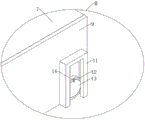
FIG. 1 is a schematic diagram of the overall structure of the present invention;
FIG. 2 is a schematic view of the structure of the mounting frame of the present invention;
FIG. 3 is a schematic view of the internal structure of the mounting frame of the present invention;
FIG. 4 is a schematic view of the axial side structure of the cooling tube assembly and spacing capsule of the present invention;
FIG. 5 is a schematic view of a cooling tube assembly according to the present invention;
FIG. 6 is a schematic view of the internal structure of a heated cavity cartridge of the present invention;
FIG. 7 is a schematic diagram illustrating the operation of the cooling tube assembly of the present invention;
FIG. 8 is a schematic diagram of a structure of a back plate of a server housing according to the present invention;
FIG. 9 is an enlarged view of FIG. 8A in accordance with the present invention;
FIG. 10 is a metal heat pipe diagram of the present invention;
FIG. 11 is an enlarged view of FIG. 10 at C in accordance with the present invention;
FIG. 12 is a schematic view of the heated cavity cartridge and spacing bladder connection of the present invention;
fig. 13 is an enlarged view of fig. 12 at B in accordance with the present invention.
Reference numerals in the drawings represent respectively: 1. a server housing; 2. a cooling liquid tank; 3. a semiconductor refrigeration sheet set; 4. a heat dissipation shell; 5. installing a frame body; 501. a housing frame; 502. a mounting plate; 6. a cooling tube assembly; 601. an elastic connection pipe; 602. a metal heat pipe; 6021. a heat conductive frame; 6022. an elastic arc-shaped piece; 7. a thermal motion assembly; 701. a heated cavity drum; 702. a piston plate; 703. pulling the rope; 704. an evaporation liquid cavity; 705. a passive cavity; 706. a return spring; 8. a communication assembly; 801. fixing the frame; 802. a blocking plate; 9. a limiting capsule body; 10. sealing limiting plates; 11. a limit frame; 12. a floating ring; 13. a disc; 14. an elastic sheet; 15. an elastic valve; 16. and a drain hole.
Detailed Description
In order to make the objects, technical solutions and advantages of the embodiments of the present invention more clear, the technical solutions of the embodiments of the present invention will be clearly and completely described below with reference to the accompanying drawings in the embodiments of the present invention. It will be apparent that the described embodiments are some, but not all, embodiments of the invention. All other embodiments, which can be made by those skilled in the art based on the embodiments of the invention without making any inventive effort, are intended to be within the scope of the invention.
The invention is further described below with reference to examples.
Examples:
the liquid cooling server system comprises a server shell 1, a mounting frame 5 and a liquid cooling component, wherein the server shell is used for mounting the liquid cooling component on the surface;
the installation frame body 5 can accommodate related electronic devices, is detachably installed on the server shell 1 and is connected with the liquid cooling assembly;
a cooling tube assembly 6 that covers the inside of the mounting frame 5 and cools the electronic device connected to the mounting frame 5;
the liquid cooling assembly comprises a cooling liquid tank 2 fixedly arranged at the top of the server shell 1, a semiconductor refrigeration sheet group 3 is fixedly connected to the top of the cooling liquid tank 2, and a heat dissipation shell 4 is fixedly arranged at the top of the semiconductor refrigeration sheet group 3.
Specifically, referring to fig. 1 to 13, the mounting frame 5 includes a housing frame 501 and a mounting plate 502, the housing frame 501 and the mounting plate 502 are fixedly connected, a cavity structure is formed inside the housing frame 501, four groups of cooling tube assemblies 6 are slidably connected to an inner wall of the housing frame 501, the cooling tube assemblies 6 are connected with the liquid cooling assemblies in a communicating manner, each group of cooling tube assemblies 6 is mounted on two adjacent side walls of the inner wall of the housing frame 501, two ends of each group of cooling tube assemblies 6 are respectively close to middle positions of two adjacent side walls of the housing frame 501, four groups of heat actuating assemblies 7 and limiting capsules 9 are fixedly mounted on an outer side wall of the housing frame 501, and the four groups of heat actuating assemblies 7 and the limiting capsules 9 are in one-to-one correspondence with the cooling tube assemblies 6;
the heat action assembly 7 comprises two heated cavity barrels 701 distributed on the outer side of each group of cooling pipe assemblies 6, the two heated cavity barrels 701 are respectively located on two sides of each group of cooling pipe assemblies 6, a piston plate 702 is slidably installed in each heated cavity barrel 701, the interior of each heated cavity barrel 701 is divided into an evaporating liquid cavity 704 and a driven cavity 705 by the piston plate 702, a pulling rope 703 is fixedly connected to one side of each piston plate 702, the pulling rope 703 is slidably inserted on a side plate of each heated cavity barrel 701, the two pulling ropes 703 are respectively and fixedly installed on the cooling pipe assemblies 6 located on different sides of the containing frame 501, and a reset spring 706 is fixedly connected between one side of each piston plate 702 and the inner side wall of each heated cavity barrel 701.
Specifically, referring to fig. 1 to 13, the cooling tube assembly 6 includes an elastic connection tube 601 and a plurality of metal heat pipes 602 penetrating through a back plate of the accommodating frame 501, the metal heat pipes 602 are fixedly connected to one side of the elastic connection tube 601, each of the metal heat pipes 602 is fixedly connected with 603, a communication assembly 8 is fixedly installed in the back plate of the server housing 1, the communication assembly 8 is communicated with the cooling liquid tank 2, and the elastic connection tube 601 is inserted into the communication assembly 8.
In daily use, the installation frame 5 provides expandable conditions for the server housing 1, electronic devices can be accommodated in the expandable conditions, during the working process of liquid cooling, the semiconductor refrigeration sheet set 3 and the water pump in the cooling liquid tank 2 are started to enable water flow to enter the elastic connecting pipe 601 inserted in the communicating component 8 and flow out of the other elastic connecting pipe 601 in the same set, wherein the water pump drives the water flow mode and the water path are not shown in the drawings, the water flow is not repeated in the drawings, the cooling effect is realized, when overheat occurs at a certain position of the electronic devices in the installation frame 5, the heated cavity barrels 701 positioned at different positions can receive heat transfer, and the heat transfer can enable evaporating liquid in the passive cavity 705 to evaporate rapidly, the air pressure in the passive cavity 705 is increased, the piston plate 702 is pushed to move towards the space of the evaporating liquid cavity 704, and is transferred to the metal heat-conducting pipes 602 on the other side of the containing frame 501 by the pulling rope 703, and is pulled to slide upwards, and along with the continuous movement of the piston plate 702, the metal heat-conducting pipes 602 on the other side of the containing frame 501 are pulled down to one side of the heat-generating part in the heat-generating containing frame 501, and the number and density of the metal heat-conducting pipes 602 on the heat-generating part side of the containing frame 501 are increased (as shown in fig. 7, the arrow position in fig. 7 is the movable direction of the metal heat-conducting pipes 602), so that the cooling effect of the heat-generating part of the containing frame 501 can be promoted, the temperature of the heat-generating part can be quickly reduced, and the cooling effect can be improved.
It should be noted that, the metal heat-conducting tube 602 is only firmly attached to the inner wall of the accommodating frame 501 under the limiting action of the limiting capsule 9, and the piston plate 702 is reset under the elastic action of the reset spring 706, while the metal heat-conducting tube 602 is deformed when moving, and after the piston plate 702 is reset, the elastic connection tube 601 drives the metal heat-conducting tube 602 to reset.
Specifically, referring to fig. 1 to 13, the communication assembly 8 includes a fixed frame 801 fixedly installed on the back plate of the server housing 1, two blocking plates 802 are elastically rotatably installed on the inner side of the fixed frame 801, and the elastic connection pipe 601 is inserted into the fixed frame 801.
When the installation frame body 5 is replaced or detached according to the expansibility requirement, the elastic connecting pipe 601 in the installation frame body 5 loses the connection with the fixed frame body 801, the waterway flowing out or flowing in the cooling liquid tank 2 cannot flow outwards through the communication component 8, when the installation frame body 5 is installed, the elastic connecting pipe 601 in the installation frame body 5 pushes the blocking plate 802 inwards, the position of the blocking plate 802 turns over, the port of the fixed frame body 801 is opened, and at the moment, water flow can flow into the elastic connecting pipe 601 and the metal heat conducting pipe 602 so as to meet the expansibility of the whole device.
Specifically, referring to fig. 1 to 13, the cooling tube assembly 6 includes a heat conducting frame 6021 and an elastic arc-shaped piece 6022 located above the heat conducting frame 6021, the elastic arc-shaped piece 6022 is fixedly connected with the heat conducting frame 6021, and the elastic arc-shaped piece 6022 contacts with the limiting capsule 9.
Specifically, referring to fig. 1 to 13, both sides of the heated cavity cylinder 701 are provided with a limiting capsule 9 and are mutually communicated with the limiting capsule 9 through a through hole, the through hole is located on two side plates of the space of the evaporating liquid cavity 704, a limiting frame 11 is fixedly connected to the communicating part of the inner side of the limiting capsule 9 and the heated cavity cylinder 701, a floating ring 12 is slidably mounted in the limiting frame 11, an elastic sheet 14 is fixedly connected to the outer side of the floating ring 12, a disc 13 is fixedly connected to one side of the elastic sheet 14, and the disc 13 is movably mounted in the floating ring 12 in an embedded manner.
In the continuous evaporation process of the evaporating liquid in the passive cavity 705, the evaporated gas pushes the piston plate 702 to the limit position, namely, the contraction limit position of the return spring 706, the position of the metal heat-conducting tube 602 is moved to be completed, the evaporating liquid still evaporates at the moment, the pressure generated by the evaporated gas can enable the disc 13 to break through the elasticity of the elastic sheet 14 to overturn, the gas of the evaporating liquid can enter the cavity of the limiting capsule 9 through the floating ring 12 to expand the limiting capsule 9, and the elastic arc-shaped sheet 6022 is pressed to generate inward concave deformation action after the limiting capsule 9 expands until the elastic arc-shaped sheet 6022 completes the inward concave deformation, and the cross-sectional area of the metal heat-conducting tube 602 is reduced, so that the flow rate of the liquid in the metal heat-conducting tube 602 at the heating position of the containing frame 501 is increased, and the cooling effect on the position can be increased.
It should be noted that after the metal heat-conducting tube 602 and the limiting capsule 9 are finished, the evaporating liquid in the limiting capsule 9 is solidified into liquid, and the piston plate 702 is reset, so that the position of the evaporating liquid cavity 704 generates negative pressure, the floating ring 12 rises under the buoyancy effect along with the increase of the liquid level of the evaporating liquid, the through hole between the heated cavity barrel 701 and the limiting capsule 9 is opened, and the evaporating liquid is sucked back into the heated cavity barrel 701 by the negative pressure through the through hole between the heated cavity barrel 701 and the limiting capsule 9 for the next use.
Specifically, referring to fig. 1 to 13, elastic valves 15 are fixedly installed in both sides of the metal heat pipes 602 between the same group of two pulling ropes 703, and sealing limiting plates 10 are fixedly connected to the outer sides of the two metal heat pipes 602 fixedly connected to the heated cavity cylinder 701.
Specifically, referring to fig. 1 to 13, a drain hole 16 is formed at a position corresponding to a group of cooling tube assemblies 6 at the back plate of the server housing 1, and the drain hole 16 is communicated with the cooling liquid tank 2.
When the metal heat conduction pipe 602 flows liquid, the elastic valve 15 can bear the pressure generated by water flow, after the two metal heat conduction pipes 602 connected with the pulling rope 703 are moved, the limiting bag body 9 presses the metal heat conduction pipe 602, the pressure in the metal heat conduction pipe 602 gradually increases in the process of reducing the cross-section area of the metal heat conduction pipe 602, part of water flow overflows from the elastic valve 15 under the action of extrusion force, meanwhile, the part of liquid stays in a closed space formed by the two sealing limiting plates 10 and the limiting bag body 9, a certain cooling effect is achieved on the containing frame 501, part of liquid flows back from the drainage hole 16 along with complete extrusion of the liquid, after the metal heat conduction pipe 602 is deformed, the side water flow speed of the elastic valve 15 increases, the extrusion force of the elastic arc-shaped piece 6022 is lost, and according to the Berry principle, the larger flow speed is, the smaller the elastic valve 15 can still keep the sealing effect on the heat conduction frame 6021, and the water flow can still flow in the heat conduction frame 6021.
Working principle: the mounting frame 5 provides expandable conditions for the server housing 1, in which electronic devices can be accommodated, during the liquid cooling operation, the semiconductor refrigeration sheet set 3 and the water pump in the cooling liquid tank 2 are started to enable water flow to enter the elastic connecting pipe 601 inserted in the communication assembly 8 and flow out of the other elastic connecting pipe 601 in the same set, wherein the manner of the water pump driving the water flow and the arrangement of the water path belong to the prior art, not shown in the drawings, are not repeated herein, the cooling effect is assisted by the water flow, when overheat occurs at a certain position of the electronic devices in the mounting frame 5, the heated cavity barrels 701 positioned at different positions can receive heat transfer, and the heat transfer can enable the evaporating liquid in the passive cavity 705 to evaporate rapidly, the air pressure in the passive cavity 705 is increased, the piston plate 702 is pushed to move towards the space of the evaporating liquid cavity 704, and is transferred to the metal heat-conducting pipes 602 on the other side of the containing frame 501 by the pulling rope 703, and is pulled to slide upwards, and along with the continuous movement of the piston plate 702, the metal heat-conducting pipes 602 on the other side of the containing frame 501 are pulled down to one side of the heat-generating part in the heat-generating containing frame 501, and the number and density of the metal heat-conducting pipes 602 on the heat-generating part side of the containing frame 501 are increased (as shown in fig. 7, the arrow position in fig. 7 is the movable direction of the metal heat-conducting pipes 602), so that the cooling effect of the heat-generating part of the containing frame 501 can be promoted, the temperature of the heat-generating part can be quickly reduced, and the cooling effect can be improved.
The above embodiments are only for illustrating the technical solution of the present invention, and are not limiting; although the invention has been described in detail with reference to the foregoing embodiments, it will be understood by those of ordinary skill in the art that: the technical scheme described in the foregoing embodiments can be modified or some technical features thereof can be replaced by equivalents; these modifications or substitutions do not depart from the essence of the corresponding technical solutions from the protection scope of the technical solutions of the embodiments of the present invention.
Claims (8)
1. A liquid-cooled server system, comprising:
the server housing (1) is used for installing the installation frame body (5) and installing the liquid cooling component on the surface;
the installation frame body (5) can accommodate related electronic devices, is detachably installed on the server shell (1) and is connected with the liquid cooling assembly;
a cooling tube assembly (6) which covers the inside of the mounting frame (5) and cools the electronic device connected to the mounting frame (5);
the liquid cooling assembly comprises a cooling liquid tank (2) fixedly arranged at the top of the server shell (1), a semiconductor refrigeration sheet group (3) is fixedly connected to the top of the cooling liquid tank (2), and a heat dissipation shell (4) is fixedly arranged at the top of the semiconductor refrigeration sheet group (3).
2. The liquid-cooled server system according to claim 1, wherein the installation frame body (5) comprises an accommodating frame (501) and an installation plate (502), the accommodating frame (501) is fixedly connected with the installation plate (502), a cavity structure is formed inside the accommodating frame (501), four groups of cooling pipe assemblies (6) are slidably connected to the inner layer wall of the accommodating frame (501), the cooling pipe assemblies (6) are communicated and connected with the liquid cooling assemblies, each group of cooling pipe assemblies (6) is installed on two adjacent side walls of the inner layer wall of the accommodating frame (501), two ends of each group of cooling pipe assemblies (6) are respectively close to the middle positions of two adjacent side walls of the accommodating frame (501), four groups of heat actuating assemblies (7) and limiting capsules (9) are fixedly installed on the outer side wall of the accommodating frame (501), and the four groups of heat actuating assemblies (7) and the limiting capsules (9) are in one-to-one correspondence with the cooling pipe assemblies (6);
the heat action assembly (7) comprises two heated cavity barrels (701) distributed on the outer side of each group of cooling pipe assemblies (6), the two heated cavity barrels (701) are respectively located on two sides of each group of cooling pipe assemblies (6), a piston plate (702) is slidably installed in each heated cavity barrel (701), the piston plate (702) divides the interior of each heated cavity barrel (701) into an evaporating liquid cavity (704) and a passive cavity (705), a pulling rope (703) is fixedly connected to one side of each piston plate (702), the pulling rope (703) is slidably inserted on a side plate of each heated cavity barrel (701), the two pulling ropes (703) are respectively fixedly installed on the cooling pipe assemblies (6) located on different sides of each containing frame (501), and a reset spring (706) is fixedly connected between one side of each piston plate (702) and the inner side wall of each heated cavity barrel (701).
3. The liquid-cooled server system according to claim 2, wherein the cooling pipe assembly (6) comprises an elastic connecting pipe (601) and a plurality of metal heat pipes (602) penetrating through a back plate of the accommodating frame (501), the metal heat pipes (602) are fixedly connected to one side of the elastic connecting pipe (601), each metal heat pipe (602) is fixedly connected with a connecting component (603), a communication component (8) is fixedly installed in the back plate of the server shell (1), the communication component (8) is communicated with the cooling liquid tank (2), and the elastic connecting pipe (601) is inserted into the communication component (8).
4. A liquid-cooled server system according to claim 3, characterized in that the communication assembly (8) comprises a fixed frame (801) fixedly mounted on the back plate of the server housing (1), two blocking plates (802) are mounted on the inner side of the fixed frame (801) in an elastic rotation manner, and the elastic connecting pipe (601) is inserted into the fixed frame (801).
5. A liquid cooled server system according to claim 3, wherein the cooling tube assembly (6) comprises a heat conducting frame (6021) and an elastic arc-shaped sheet (6022) located above the heat conducting frame (6021), the elastic arc-shaped sheet (6022) is fixedly connected with the heat conducting frame (6021), and the elastic arc-shaped sheet (6022) is contacted with the limiting capsule (9).
6. The liquid-cooled server system according to claim 5, wherein both sides of the heated cavity cylinder (701) are provided with a limiting capsule (9) and are mutually communicated with the limiting capsule (9) through a through hole, the through hole is positioned on both side plates of the evaporating liquid cavity (704) space, a limiting frame (11) is fixedly connected at the communicating position between the inner side of the limiting capsule (9) and the heated cavity cylinder (701), a floating ring (12) is slidably mounted in the limiting frame (11), an elastic sheet (14) is fixedly connected on the outer side of the floating ring (12), a disc (13) is fixedly connected on one side of the elastic sheet (14), and the disc (13) is movably mounted in the floating ring (12).
7. The liquid-cooled server system of claim 6, wherein elastic valves (15) are fixedly installed in the two sides of the metal heat-conducting pipes (602) between the same group of two pulling ropes (703), and sealing limiting plates (10) are fixedly connected to the outer sides of the two metal heat-conducting pipes (602) fixedly connected with the heated cavity cylinder (701).
8. The liquid-cooled server system of claim 7, wherein a drain hole (16) is formed at a back plate of the server housing (1) at a position corresponding to a group of cooling tube assemblies (6), and the drain hole (16) is communicated with the cooling liquid tank (2).
Priority Applications (1)
| Application Number | Priority Date | Filing Date | Title |
|---|---|---|---|
| CN202310304845.9A CN116056432B (en) | 2023-03-27 | 2023-03-27 | Liquid-cooled server system |
Applications Claiming Priority (1)
| Application Number | Priority Date | Filing Date | Title |
|---|---|---|---|
| CN202310304845.9A CN116056432B (en) | 2023-03-27 | 2023-03-27 | Liquid-cooled server system |
Publications (2)
| Publication Number | Publication Date |
|---|---|
| CN116056432A true CN116056432A (en) | 2023-05-02 |
| CN116056432B CN116056432B (en) | 2023-06-30 |
Family
ID=86122114
Family Applications (1)
| Application Number | Title | Priority Date | Filing Date |
|---|---|---|---|
| CN202310304845.9A Active CN116056432B (en) | 2023-03-27 | 2023-03-27 | Liquid-cooled server system |
Country Status (1)
| Country | Link |
|---|---|
| CN (1) | CN116056432B (en) |
Cited By (1)
| Publication number | Priority date | Publication date | Assignee | Title |
|---|---|---|---|---|
| CN121523519A (en) * | 2026-01-15 | 2026-02-13 | 上海远图未来信息技术有限公司 | A cooling device, electronic equipment, and a method for installing the cooling device. |
Citations (7)
| Publication number | Priority date | Publication date | Assignee | Title |
|---|---|---|---|---|
| CN102130080A (en) * | 2010-11-11 | 2011-07-20 | 华为技术有限公司 | Heat radiation device |
| CN110553384A (en) * | 2018-05-31 | 2019-12-10 | 浙江美尔凯特智能厨卫股份有限公司 | Air conditioner and condensate water treatment system thereof |
| CN212960955U (en) * | 2020-10-13 | 2021-04-13 | 广东凯乐斯光电科技有限公司 | LED lamp with good heat dissipation effect |
| CN216596125U (en) * | 2021-12-23 | 2022-05-24 | 深圳市世芯信息技术有限公司 | Heat radiator for server system |
| CN216648997U (en) * | 2021-11-19 | 2022-05-31 | 山东高正电气有限公司 | High-efficient heat dissipation type switch board |
| CN217404830U (en) * | 2022-04-01 | 2022-09-09 | 苏州国科综合数据中心有限公司 | Liquid cooling phase change heat abstractor of high density server |
| CN218183801U (en) * | 2022-07-08 | 2022-12-30 | 深圳键桥轨道交通有限公司 | Heat dissipation device for rail transit communication equipment |
-
2023
- 2023-03-27 CN CN202310304845.9A patent/CN116056432B/en active Active
Patent Citations (7)
| Publication number | Priority date | Publication date | Assignee | Title |
|---|---|---|---|---|
| CN102130080A (en) * | 2010-11-11 | 2011-07-20 | 华为技术有限公司 | Heat radiation device |
| CN110553384A (en) * | 2018-05-31 | 2019-12-10 | 浙江美尔凯特智能厨卫股份有限公司 | Air conditioner and condensate water treatment system thereof |
| CN212960955U (en) * | 2020-10-13 | 2021-04-13 | 广东凯乐斯光电科技有限公司 | LED lamp with good heat dissipation effect |
| CN216648997U (en) * | 2021-11-19 | 2022-05-31 | 山东高正电气有限公司 | High-efficient heat dissipation type switch board |
| CN216596125U (en) * | 2021-12-23 | 2022-05-24 | 深圳市世芯信息技术有限公司 | Heat radiator for server system |
| CN217404830U (en) * | 2022-04-01 | 2022-09-09 | 苏州国科综合数据中心有限公司 | Liquid cooling phase change heat abstractor of high density server |
| CN218183801U (en) * | 2022-07-08 | 2022-12-30 | 深圳键桥轨道交通有限公司 | Heat dissipation device for rail transit communication equipment |
Cited By (1)
| Publication number | Priority date | Publication date | Assignee | Title |
|---|---|---|---|---|
| CN121523519A (en) * | 2026-01-15 | 2026-02-13 | 上海远图未来信息技术有限公司 | A cooling device, electronic equipment, and a method for installing the cooling device. |
Also Published As
| Publication number | Publication date |
|---|---|
| CN116056432B (en) | 2023-06-30 |
Similar Documents
| Publication | Publication Date | Title |
|---|---|---|
| US9261308B2 (en) | Pump-enhanced, sub-cooling of immersion-cooling fluid | |
| NL2014466B1 (en) | Module for cooling a heat generating component. | |
| US8867209B2 (en) | Two-phase, water-based immersion-cooling apparatus with passive deionization | |
| US20140068942A1 (en) | Vapor condenser with three-dimensional folded structure | |
| CN101751096B (en) | Evaporation-cooled device attached to surface of super computer | |
| CN114828548B (en) | Chassis, electronic equipment and chassis exhaust method | |
| CN116056432A (en) | Liquid-cooled server system | |
| CN113260235A (en) | Immersion cooling system and electronic equipment | |
| TW202303069A (en) | Boiling and cooling device | |
| KR20080041979A (en) | Heat dissipation system and heat dissipation community | |
| JP2011210776A (en) | Liquid cooling type cooling device | |
| CN214751757U (en) | Spraying phase-change cooling server heat dissipation system | |
| US12284786B2 (en) | Fluid phase change thermal management arrangement and method | |
| CN112911903A (en) | Circuit board heat dissipation device | |
| CN115942709A (en) | Three-dimensional phase change radiator | |
| CN103917074B (en) | The display of special purpose | |
| CN118215275A (en) | Solid-state uniform-temperature composite phase-change energy storage radiator | |
| CN118658646A (en) | A heat removal system for a small offshore reactor containment and its containment | |
| CN106686954B (en) | Heat dissipation structure, electronic equipment and assembling method thereof | |
| CN211777839U (en) | Wind driven generator adopting heat pipe radiator | |
| WO2022170687A1 (en) | Water-cooling heat dissipator and water-cooling heat dissipation system | |
| CN209627965U (en) | A kind of phase-change heat equipment | |
| CN224083921U (en) | A heat dissipation device for power electronic equipment and a photovoltaic inverter having the same. | |
| KR200500293Y1 (en) | 3D microcrystalline heat dissipation device | |
| CN223934558U (en) | A liquid-cooled charging pile with a sealed structure |
Legal Events
| Date | Code | Title | Description |
|---|---|---|---|
| PB01 | Publication | ||
| PB01 | Publication | ||
| SE01 | Entry into force of request for substantive examination | ||
| SE01 | Entry into force of request for substantive examination | ||
| GR01 | Patent grant | ||
| GR01 | Patent grant |