CN115769440A - Conductor terminal - Google Patents
Conductor terminal Download PDFInfo
- Publication number
- CN115769440A CN115769440A CN202180043688.XA CN202180043688A CN115769440A CN 115769440 A CN115769440 A CN 115769440A CN 202180043688 A CN202180043688 A CN 202180043688A CN 115769440 A CN115769440 A CN 115769440A
- Authority
- CN
- China
- Prior art keywords
- conductor
- clamping
- lever
- spring
- housing
- Prior art date
- Legal status (The legal status is an assumption and is not a legal conclusion. Google has not performed a legal analysis and makes no representation as to the accuracy of the status listed.)
- Pending
Links
Images




Classifications
-
- H—ELECTRICITY
- H01—ELECTRIC ELEMENTS
- H01R—ELECTRICALLY-CONDUCTIVE CONNECTIONS; STRUCTURAL ASSOCIATIONS OF A PLURALITY OF MUTUALLY-INSULATED ELECTRICAL CONNECTING ELEMENTS; COUPLING DEVICES; CURRENT COLLECTORS
- H01R13/00—Details of coupling devices of the kinds covered by groups H01R12/70 or H01R24/00 - H01R33/00
- H01R13/62—Means for facilitating engagement or disengagement of coupling parts or for holding them in engagement
- H01R13/629—Additional means for facilitating engagement or disengagement of coupling parts, e.g. aligning or guiding means, levers, gas pressure electrical locking indicators, manufacturing tolerances
-
- H—ELECTRICITY
- H01—ELECTRIC ELEMENTS
- H01R—ELECTRICALLY-CONDUCTIVE CONNECTIONS; STRUCTURAL ASSOCIATIONS OF A PLURALITY OF MUTUALLY-INSULATED ELECTRICAL CONNECTING ELEMENTS; COUPLING DEVICES; CURRENT COLLECTORS
- H01R4/00—Electrically-conductive connections between two or more conductive members in direct contact, i.e. touching one another; Means for effecting or maintaining such contact; Electrically-conductive connections having two or more spaced connecting locations for conductors and using contact members penetrating insulation
- H01R4/28—Clamped connections, spring connections
- H01R4/48—Clamped connections, spring connections utilising a spring, clip, or other resilient member
- H01R4/4809—Clamped connections, spring connections utilising a spring, clip, or other resilient member using a leaf spring to bias the conductor toward the busbar
- H01R4/4811—Spring details
- H01R4/4816—Spring details the spring shape preventing insertion of the conductor end when the spring is unbiased
-
- H—ELECTRICITY
- H01—ELECTRIC ELEMENTS
- H01R—ELECTRICALLY-CONDUCTIVE CONNECTIONS; STRUCTURAL ASSOCIATIONS OF A PLURALITY OF MUTUALLY-INSULATED ELECTRICAL CONNECTING ELEMENTS; COUPLING DEVICES; CURRENT COLLECTORS
- H01R4/00—Electrically-conductive connections between two or more conductive members in direct contact, i.e. touching one another; Means for effecting or maintaining such contact; Electrically-conductive connections having two or more spaced connecting locations for conductors and using contact members penetrating insulation
- H01R4/28—Clamped connections, spring connections
- H01R4/48—Clamped connections, spring connections utilising a spring, clip, or other resilient member
- H01R4/4809—Clamped connections, spring connections utilising a spring, clip, or other resilient member using a leaf spring to bias the conductor toward the busbar
- H01R4/4828—Spring-activating arrangements mounted on or integrally formed with the spring housing
- H01R4/483—Pivoting arrangements, e.g. lever pushing on the spring
-
- H—ELECTRICITY
- H01—ELECTRIC ELEMENTS
- H01R—ELECTRICALLY-CONDUCTIVE CONNECTIONS; STRUCTURAL ASSOCIATIONS OF A PLURALITY OF MUTUALLY-INSULATED ELECTRICAL CONNECTING ELEMENTS; COUPLING DEVICES; CURRENT COLLECTORS
- H01R4/00—Electrically-conductive connections between two or more conductive members in direct contact, i.e. touching one another; Means for effecting or maintaining such contact; Electrically-conductive connections having two or more spaced connecting locations for conductors and using contact members penetrating insulation
- H01R4/28—Clamped connections, spring connections
- H01R4/48—Clamped connections, spring connections utilising a spring, clip, or other resilient member
- H01R4/4809—Clamped connections, spring connections utilising a spring, clip, or other resilient member using a leaf spring to bias the conductor toward the busbar
- H01R4/4846—Busbar details
- H01R4/485—Single busbar common to multiple springs
-
- H—ELECTRICITY
- H01—ELECTRIC ELEMENTS
- H01R—ELECTRICALLY-CONDUCTIVE CONNECTIONS; STRUCTURAL ASSOCIATIONS OF A PLURALITY OF MUTUALLY-INSULATED ELECTRICAL CONNECTING ELEMENTS; COUPLING DEVICES; CURRENT COLLECTORS
- H01R12/00—Structural associations of a plurality of mutually-insulated electrical connecting elements, specially adapted for printed circuits, e.g. printed circuit boards [PCB], flat or ribbon cables, or like generally planar structures, e.g. terminal strips, terminal blocks; Coupling devices specially adapted for printed circuits, flat or ribbon cables, or like generally planar structures; Terminals specially adapted for contact with, or insertion into, printed circuits, flat or ribbon cables, or like generally planar structures
- H01R12/50—Fixed connections
- H01R12/51—Fixed connections for rigid printed circuits or like structures
- H01R12/515—Terminal blocks providing connections to wires or cables
-
- H—ELECTRICITY
- H01—ELECTRIC ELEMENTS
- H01R—ELECTRICALLY-CONDUCTIVE CONNECTIONS; STRUCTURAL ASSOCIATIONS OF A PLURALITY OF MUTUALLY-INSULATED ELECTRICAL CONNECTING ELEMENTS; COUPLING DEVICES; CURRENT COLLECTORS
- H01R4/00—Electrically-conductive connections between two or more conductive members in direct contact, i.e. touching one another; Means for effecting or maintaining such contact; Electrically-conductive connections having two or more spaced connecting locations for conductors and using contact members penetrating insulation
- H01R4/28—Clamped connections, spring connections
- H01R4/48—Clamped connections, spring connections utilising a spring, clip, or other resilient member
- H01R4/4809—Clamped connections, spring connections utilising a spring, clip, or other resilient member using a leaf spring to bias the conductor toward the busbar
- H01R4/48185—Clamped connections, spring connections utilising a spring, clip, or other resilient member using a leaf spring to bias the conductor toward the busbar adapted for axial insertion of a wire end
- H01R4/4819—Clamped connections, spring connections utilising a spring, clip, or other resilient member using a leaf spring to bias the conductor toward the busbar adapted for axial insertion of a wire end the spring shape allowing insertion of the conductor end when the spring is unbiased
- H01R4/4821—Single-blade spring
Landscapes
- Connections Arranged To Contact A Plurality Of Conductors (AREA)
- Cable Accessories (AREA)
- Insulated Conductors (AREA)
- Superconductors And Manufacturing Methods Therefor (AREA)
Abstract
Description
相关申请的交叉引用Cross References to Related Applications
本申请要求2020年5月19日提交的美国临时申请号63/040,815的优先权,该申请通过引用整体并入本文。This application claims priority to U.S. Provisional Application No. 63/040,815, filed May 19, 2020, which is hereby incorporated by reference in its entirety.
背景技术Background technique
美国专利号9,466,895和美国专利号8,794,994中描述了导体端子,其中每一篇都通过引用整体并入本文。Conductor terminals are described in US Patent No. 9,466,895 and US Patent No. 8,794,994, each of which is incorporated herein by reference in its entirety.
美国专利号9,466,895描述了导体端子,其包括由绝缘材料制成的壳体、至少一个弹力夹紧连接器和以可旋转的方式容纳在壳体中的至少一个驱动元件,驱动元件设计成在每种情况下都能打开至少一个分配的弹力夹紧连接器。驱动元件包括彼此间隔开的两个杠杆臂部分,所述杠杆臂部分至少部分地与枢转支承区域突出到壳体中,所述杠杆臂部分彼此连接,并且通过到杠杆臂的横向连接件相对于枢转支承区域间隔开。在布置有至少一个驱动元件的壳体的一侧上,所述至少一个弹力夹紧连接器被壳体的外边界壁覆盖,并且从邻近于相应分配弹力夹紧连接器的侧壁部分的两侧上的外边界壁延伸至壳体的内部空间。US Patent No. 9,466,895 describes a conductor terminal comprising a housing made of insulating material, at least one spring clamp connector and at least one drive element rotatably accommodated in the housing, the drive element being designed to In either case, at least one assigned spring-loaded clamping connector can be opened. The drive element comprises two lever arm parts spaced apart from each other, said lever arm parts protruding into the housing at least partially with the pivot bearing area, said lever arm parts being connected to each other and opposite by means of a transverse connection to the lever arms spaced apart from the pivot bearing area. On the side of the housing on which at least one drive element is arranged, said at least one spring clamping connector is covered by the outer boundary wall of the housing, and from two sides of the side wall part adjacent to the corresponding distribution spring clamping connector The outer boundary walls on the sides extend into the inner space of the housing.
美国专利号8,794,994描述了具有至少一个母线片和至少一个夹紧弹簧的接线端子。接线端子具有至少一个由夹紧弹簧和母线片的一部分形成的弹簧力夹紧连接、包括至少一个导体插入开口(该开口通向弹簧力夹紧连接且在导体插入方向上延伸)的绝缘材料壳体,以及至少一个设计成与至少一个夹紧弹簧相互作用以打开至少一个弹簧力夹紧连接的可枢转地安装的操作杆。操作杆可以布置成其旋转轴线位于导体插入开口中或在夹紧点方向上的导体插入开口的路径中。接线端子提供了节省空间和紧凑的结构,这在操作杆的力效应方面也得到了改进。US Patent No. 8,794,994 describes a terminal block having at least one bus bar and at least one clamping spring. The terminal has at least one spring-force clamping connection formed by a clamping spring and a part of the busbar, a housing of insulating material comprising at least one conductor insertion opening leading into the spring-force clamping connection and extending in the conductor insertion direction body, and at least one pivotably mounted operating lever designed to interact with at least one clamping spring to open at least one spring force clamping connection. The operating lever can be arranged with its axis of rotation in the conductor insertion opening or in the path of the conductor insertion opening in the direction of the clamping point. The terminal block provides a space-saving and compact construction, which is also improved with regard to the force effect of the operating lever.
发明内容Contents of the invention
在本公开的第一方面,公开了一种导体连接夹。所述夹包括母线和夹紧弹簧,夹紧弹簧包括用于将电导体夹持到母线的主要部分(主要部分和母线限定夹紧弹簧连接),以及与主要部分相邻并刚性连接到主要部分的弹簧构件。连接夹还包括限定通向夹紧弹簧连接的导体插入开口的壳体,以及操作杆,该操作杆被配置为向弹簧构件施加力,以使主要部分偏转从而打开夹紧弹簧连接。In a first aspect of the present disclosure, a conductor connection clip is disclosed. The clip comprises a busbar and a clamping spring comprising a main part for clamping an electrical conductor to the busbar (the main part and the busbar defining a clamping spring connection), and a main part adjacent to and rigidly connected to the main part the spring member. The connection clip also includes a housing defining a conductor insertion opening to the pinch spring connection, and an operating lever configured to apply a force to the spring member to deflect the main portion to open the pinch spring connection.
在第一方面的实施方式中,导体连接夹包括构造成支撑操作杆的支承臂,操作杆包括杠杆臂和楔形部分,杠杆臂的驱动导致楔形部分楔入支承臂和弹簧构件之间,从而向弹簧构件施加力。In an embodiment of the first aspect, the conductor connection clip includes a support arm configured to support an operating lever, the operating lever comprising a lever arm and a wedge portion, actuation of the lever arm causing the wedge portion to wedge between the support arm and the spring member, thereby The spring member applies the force.
在第一方面的实施方式中,操作杆可旋转地安装,并包括枢转部分,枢转部分与楔形部分相邻,其中支承臂支撑枢转元件。In an embodiment of the first aspect, the operating lever is rotatably mounted and includes a pivot portion adjacent to the wedge portion, wherein the support arm supports the pivot member.
在第一方面的实施方式中,主要部分和弹簧构件由整体材料制成。In an embodiment of the first aspect the main part and the spring member are made of a unitary material.
在第一方面的实施方式中,弹簧构件是第一弹簧构件,夹紧弹簧还包括刚性地连接到主要部分的第二弹簧构件。In an embodiment of the first aspect, the spring member is a first spring member and the clamping spring further comprises a second spring member rigidly connected to the main part.
在第一方面的实施方式中,第一和第二弹簧构件设置在主要部分的相对侧。In an embodiment of the first aspect, the first and second spring members are arranged on opposite sides of the main part.
在第一方面的实施方式中,夹紧弹簧还包括底座部分,其中弹簧构件和主要部分都沿着导体插入方向从底座部分延伸。In an embodiment of the first aspect, the clamping spring further includes a base portion, wherein both the spring member and the main portion extend from the base portion along the conductor insertion direction.
在第一方面的实施方式中,主要部分比弹簧构件在导体插入方向上延伸得更远。In an embodiment of the first aspect, the main portion extends further in the conductor insertion direction than the spring member.
在第一方面的实施方式中,导体插入开口的中心轴线偏离夹紧弹簧连接的位置。In an embodiment of the first aspect, the central axis of the conductor insertion opening is offset from the position of the clamping spring connection.
在第一方面的实施方式中,操作杆包括绝缘壁,该绝缘壁被配置为将导体从导体插入开口引导至夹紧弹簧连接。In an embodiment of the first aspect, the operating lever comprises an insulating wall configured to guide the conductor from the conductor insertion opening to the clamping spring connection.
在第一方面的实施方式中,操作杆被配置为与夹紧弹簧相互作用,以便在施力点处向弹簧构件施加力,以在打开状态和闭合状态之间驱动夹紧弹簧连接,其中操作杆可旋转地连接到壳体,并被配置为围绕旋转轴线旋转,导体插入开口沿着导体插入方向通向夹紧弹簧连接,并且该施力点在打开状态下位于与插入方向平行且包括该旋转轴线的平面的第一侧上,其中在闭合状态下施力点位于该平面的第二侧上。In an embodiment of the first aspect, the operating lever is configured to interact with the clamping spring to apply a force to the spring member at the point of application to drive the clamping spring connection between the open state and the closed state, wherein the operating lever rotatably connected to the housing and configured to rotate about an axis of rotation, the conductor insertion opening leads to the clamping spring connection in the direction of conductor insertion, and the point of application of force is located parallel to and including the axis of rotation in the open state On the first side of the plane, wherein in the closed state the force application point is on the second side of the plane.
在第一方面的实施方式中,操作杆可旋转地连接至壳体,并配置为围绕旋转轴线旋转,其中操作杆穿过旋转轴线的中点不对称。In an embodiment of the first aspect, the operating lever is rotatably connected to the housing and is configured to rotate about an axis of rotation, wherein the operating lever is asymmetrical across a midpoint of the axis of rotation.
在本公开的第二方面,公开了一种导体连接夹。该连接夹包括母线、夹紧弹簧和壳体,夹紧弹簧和母线限定夹紧弹簧连接,该夹紧弹簧连接具有闭合状态和打开状态,夹紧弹簧连接被配置为在闭合状态下将导体保持在夹紧位置,该壳体限定通向夹紧弹簧连接的导体插入开口,该插入开口限定沿着导体插入方向延伸的中心轴线。插入开口的中心轴线偏离夹紧弹簧位置。In a second aspect of the present disclosure, a conductor connection clip is disclosed. The connecting clip includes a busbar, a clamping spring and a housing, the clamping spring and the busbar define a clamping spring connection, the clamping spring connection has a closed state and an open state, the clamping spring connection is configured to hold a conductor in the closed state In the clamped position, the housing defines a conductor insertion opening to the clamping spring connection, the insertion opening defining a central axis extending along the conductor insertion direction. The central axis of the insertion opening is offset from the clamping spring position.
在第二方面的实施方式中,导体插入开口包括不对称引入部分。In an embodiment of the second aspect, the conductor insertion opening includes an asymmetric lead-in portion.
在第二方面的实施方式中,所述夹还包括可旋转安装的操作杆,该操作杆被配置为向夹紧弹簧施加力,以在闭合状态和打开状态之间驱动夹紧弹簧连接,其中操作杆围绕旋转轴线旋转,其中引入部分包括平行于旋转轴线的至少一个表面和与该至少一个平行表面不对称的相对表面。In an embodiment of the second aspect, the clip further comprises a rotatably mounted lever configured to apply a force to the clamp spring to drive the clamp spring connection between a closed state and an open state, wherein The operating lever rotates about the axis of rotation, wherein the lead-in portion includes at least one surface parallel to the axis of rotation and an opposite surface asymmetric to the at least one parallel surface.
在第二方面的实施方式中,壳体包括正面平面,其中引入部分与正面平面成非垂直角度。In an embodiment of the second aspect, the housing includes a frontal plane, wherein the lead-in portion is at a non-perpendicular angle to the frontal plane.
在第二方面的实施方式中,导体插入开口的入口部分与正面平面成非垂直角度,其中入口部分和引入部分相对于正面平面成相同角度。In an embodiment of the second aspect, the entry portion of the conductor insertion opening is at a non-perpendicular angle to the frontal plane, wherein the entry portion and the lead-in portion are at the same angle with respect to the frontal plane.
在本公开的第三方面,提供了一种导体连接夹。所述夹包括母线、用于将电导体夹持到母线的夹紧弹簧、壳体和操作杆,夹紧弹簧和母线限定具有打开状态和闭合状态的夹紧弹簧连接,壳体限定通向夹紧弹簧连接的导体插入开口,操作杆被配置为与夹紧弹簧相互作用,以便在打开状态和闭合状态之间驱动夹紧夹簧连接,操作杆包括绝缘壁,该绝缘壁被配置为将导体从导体插入开口引导到夹紧弹簧连接。In a third aspect of the present disclosure, a conductor connection clip is provided. The clip includes a busbar, a clamping spring for clamping an electrical conductor to the busbar, a housing and an operating lever, the clamping spring and the busbar defining a clamping spring connection having an open state and a closed state, the housing defining access to the clip The conductor of the clamping spring connection is inserted into the opening, the operating lever is configured to interact with the clamping spring to actuate the clamping clamping spring connection between an open state and a closed state, the operating lever includes an insulating wall configured to engage the conductor Guided from the conductor insertion opening to the clamping spring connection.
在第三方面的实施方式中,所述夹还包括配置为支撑操作杆的支承臂,其中绝缘壁设置在支承臂和导体夹紧位置之间,在导体夹紧位置,夹紧弹簧连接配置为将导体保持在闭合状态。In an embodiment of the third aspect, the clamp further comprises a support arm configured to support the operating lever, wherein the insulating wall is disposed between the support arm and a conductor clamping position in which the clamping spring connection is configured to Keep the conductor closed.
在第三方面的实施方式中,绝缘壁在闭合状态下垂直于导体插入方向突出,在打开状态下平行于导体插入方向突出。In an embodiment of the third aspect, the insulating wall protrudes perpendicularly to the conductor insertion direction in the closed state, and protrudes parallel to the conductor insertion direction in the open state.
在第三方面的实施方式中,绝缘壁围绕在打开状态和闭合状态之间垂直于导体插入方向的旋转轴线旋转。In an embodiment of the third aspect, the insulating wall rotates about an axis of rotation perpendicular to the conductor insertion direction between the open state and the closed state.
在第三方面的实施方式中,操作杆包括枢轴,该枢轴由壳体支撑并配置为围绕旋转轴线旋转,其中绝缘壁设置在枢轴和导体夹紧位置之间,在导体夹紧位置,夹紧弹簧连接配置为将导体保持在闭合状态。In an embodiment of the third aspect, the operating lever includes a pivot supported by the housing and configured to rotate about an axis of rotation, wherein the insulating wall is disposed between the pivot and the conductor clamping position, in the conductor clamping position , the clamping spring connection is configured to hold the conductor closed.
在第三方面的实施方式中,操作杆包括设置在导体夹紧位置相对侧上的两个绝缘壁,在导体夹紧位置,夹紧弹簧连接配置为将导体保持在闭合状态。In an embodiment of the third aspect, the operating lever comprises two insulating walls disposed on opposite sides of a conductor clamping position in which the clamping spring connection is configured to hold the conductor in the closed state.
在本公开的第四方面,提供了一种导体连接夹。所述夹包括母线、用于将电导体夹持到母线的夹紧弹簧、壳体和操作杆,该夹紧弹簧和母线限定了具有打开状态和闭合状态的夹紧弹簧连接,壳体限定了沿着导体插入方向通向夹紧弹簧连接的导体插入开口,操作杆被配置为与夹紧弹簧相互作用,以便在施力点处向夹紧弹簧施加力,以在打开状态和闭合状态之间驱动夹紧弹簧连接,其中,操作杆可旋转地连接到壳体且被配置为围绕旋转轴线旋转。在打开状态下,施力点位于平行于插入方向并包括旋转轴线的平面的第一侧上,其中施力点在闭合状态下位于平面的第二侧上。In a fourth aspect of the present disclosure, a conductor connection clip is provided. The clip includes a busbar, a clamping spring for clamping an electrical conductor to the busbar, a housing and an operating lever, the clamping spring and the busbar defining a clamping spring connection having an open state and a closed state, the housing defining Leading along the conductor insertion direction to the conductor insertion opening of the clamping spring connection, the operating lever is configured to interact with the clamping spring so as to apply force to the clamping spring at the force application point to actuate between the open state and the closed state A clamping spring connection, wherein the operating lever is rotatably connected to the housing and configured to rotate about an axis of rotation. In the open state, the force application point is located on a first side of a plane parallel to the insertion direction and including the axis of rotation, wherein in the closed state the force application point is located on a second side of the plane.
在第四方面的实施方式中,操作杆包括用户可操纵的杠杆臂,杠杆臂设置在平面的第一侧上。In an embodiment of the fourth aspect, the joystick includes a user-manipulable lever arm disposed on the first side of the plane.
在本公开的第五方面,提供了一种导体连接夹。所述夹包括母线、用于将电导体夹持到母线的夹紧弹簧、壳体和操作杆,该夹紧弹簧和母线限定了具有打开状态和闭合状态的夹紧弹簧连接,壳体限定了沿着导体插入方向通向夹紧弹簧连接的导体插入开口,该操作杆可旋转地连接到壳体且被配置为围绕旋转轴线旋转,操作杆被配置为与夹紧弹簧相互作用,以便在施力点处向夹紧弹簧施加力,以在打开状态和闭合状态之间驱动夹紧弹簧连接。操作杆穿过旋转轴线的中点不对称。In a fifth aspect of the present disclosure, a conductor connection clip is provided. The clip includes a busbar, a clamping spring for clamping an electrical conductor to the busbar, a housing and an operating lever, the clamping spring and the busbar defining a clamping spring connection having an open state and a closed state, the housing defining Leading to the conductor insertion opening of the clamping spring connection along the conductor insertion direction, the operating lever is rotatably connected to the housing and configured to rotate around the axis of rotation, the operating lever is configured to interact with the clamping spring so that when the clamping spring is applied Force is applied to the clamping spring at the point of force to drive the clamping spring connection between the open state and the closed state. The midpoint of the operating rod through the axis of rotation is asymmetrical.
在第五方面的实施方式中,导体连接夹具包括配置为支撑操作杆的支承臂,操作杆包括杠杆臂和楔形部分,杠杆臂的驱动使得楔形部分楔入支承臂和夹紧弹簧之间,从而向弹簧构件施加力。In an embodiment of the fifth aspect, the conductor connection clamp includes a support arm configured to support an operating lever, the operating lever comprising a lever arm and a wedge portion, actuation of the lever arm causing the wedge portion to wedge between the support arm and the clamping spring, thereby Apply force to the spring member.
在第五方面的实施方式中,操作杆可旋转地连接至壳体且配置为围绕旋转轴线旋转,其中操作杆的旋转使得楔形部分楔入支承臂和弹簧构件之间,从而向弹簧构件施加力。In an embodiment of the fifth aspect, the operating lever is rotatably connected to the housing and configured to rotate about an axis of rotation, wherein rotation of the operating lever wedges the wedge portion between the support arm and the spring member, thereby applying a force to the spring member .
在第五方面的实施方式中,操作杆可旋转地连接至壳体且配置为围绕旋转轴线旋转,其中操作杆仅包括一个枢轴,操作杆通过该枢轴连接至壳体,该枢轴由支承臂支撑。In an embodiment of the fifth aspect, the operating lever is rotatably connected to the housing and is configured to rotate about an axis of rotation, wherein the operating lever comprises only one pivot via which the operating lever is connected to the housing, the pivot being defined by Support arm support.
附图说明Description of drawings
为了更好地理解本发明的导体端子,可参考以下附图。For a better understanding of the conductor terminal of the present invention, reference may be made to the following drawings.
图1A-图1E示出了示例性导体端子的结构。1A-1E illustrate exemplary conductor terminal structures.
图2示出了示例性导体端子的结构。Fig. 2 shows the structure of an exemplary conductor terminal.
图3A-图3B示出了示例性导体端子的结构。3A-3B illustrate exemplary conductor terminal structures.
图4A-图4E示出了示例性导体端子的结构。4A-4E illustrate exemplary conductor terminal structures.
图5是示例性导体端子的等轴侧视图。Figure 5 is an isometric view of an exemplary conductor terminal.
图6是图5的示例性导体端子的主视图。FIG. 6 is a front view of the exemplary conductor terminal of FIG. 5 .
图7是图5的示例性导体端子的侧视图。FIG. 7 is a side view of the exemplary conductor terminal of FIG. 5 .
图8是图5的示例性导体端子的壳体的等轴侧视图。FIG. 8 is an isometric view of the housing of the exemplary conductor terminal of FIG. 5 .
图9A是沿着图6中的线D-D截取的图5的示例性导体端子的侧剖视图。9A is a side cross-sectional view of the exemplary conductor terminal of FIG. 5 taken along line D-D in FIG. 6 .
图9B是图9A的剖面的等轴侧视图。Figure 9B is an isometric view of the section of Figure 9A.
图10是夹紧连接处于打开状态的示例性导体端子的侧剖视图。10 is a side cross-sectional view of an exemplary conductor terminal with a clamp connection in an open state.
图11是沿着图6中的线E-E截取的图5的示例性导体端子的一部分的侧剖视图。11 is a side cross-sectional view of a portion of the exemplary conductor terminal of FIG. 5 taken along line E-E in FIG. 6 .
图12是移除了壳体的示例性导体端子的等轴侧视图。12 is an isometric view of an exemplary conductor terminal with the housing removed.
图13是图5的示例性导体端子的杠杆臂的等轴侧视图。FIG. 13 is an isometric view of a lever arm of the exemplary conductor terminal of FIG. 5 .
图14是可用于图5的示例性导体端子的示例性杠杆臂的等轴侧视图。14 is an isometric view of an example lever arm that may be used with the example conductor terminal of FIG. 5 .
图15是图5的示例性导体端子的夹紧弹簧的侧视图。15 is a side view of the clamping spring of the exemplary conductor terminal of FIG. 5 .
图16是图5的示例性导体端子的夹紧弹簧的等轴侧视图。FIG. 16 is an isometric view of the clamping spring of the exemplary conductor terminal of FIG. 5 .
图17是示出了组装导体端子的示例性方法的流程图。17 is a flowchart illustrating an exemplary method of assembling a conductor terminal.
具体实施方式Detailed ways
本文描述了改进的导体端子的实施例。Embodiments of improved conductor terminals are described herein.
在一个描述的实施例中,导体端子包括一个或多个非对称驱动元件,其设计为打开与导体端口相关的单个弹簧夹。驱动元件具有一个杠杆臂部分和沿元件长度的“L”形横截面。与支承表面相对的驱动元件的部分具有覆盖电线端口的整个宽度的表面。利用这种结构,导体端子具有以下优点:相较于具有使用两个杠杆臂部分的驱动元件的导体端子,提供了更窄的装置,更易组装,提供了相对较宽的杠杆段,从而由于只需要从用户的手/手指施加较小的压力而改善了用户体验,等等。In one described embodiment, the conductor terminal includes one or more asymmetrical actuation elements designed to open a single spring clip associated with the conductor port. The drive element has a lever arm portion and an "L" shaped cross section along the length of the element. The part of the drive element opposite the support surface has a surface covering the entire width of the wire port. With this structure, the conductor terminal has the advantages of providing a narrower device, easier assembly, providing a relatively wide lever section, and thus a relatively wide lever section, as compared to a conductor terminal having an actuating element using two lever arm parts The user experience is improved by requiring less pressure from the user's hand/fingers, etc.
在一个描述的实施例中,导体端子包括一个或多个驱动元件,其设计为打开与导体端口相关的单独的弹簧夹。驱动元件具有两个杠杆臂部分,其设计为提供用于导线进入的侧壁。这些侧壁有助于将电导体引导到其在弹簧夹内的完全就位位置。通过这种结构,导体端子具有以下益处:提供相对更容易使用和制造的导体端子,以及减少构造导体端子所需的材料数量,从而进一步降低制造成本等。In one described embodiment, the conductor terminal includes one or more actuation elements designed to open individual spring clips associated with the conductor port. The drive element has two lever arm parts designed to provide side walls for wire entry. These side walls help guide the electrical conductors into their fully seated positions within the spring clips. With this structure, the conductor terminal has the benefits of providing a conductor terminal that is relatively easier to use and manufacture, and reducing the amount of material required to construct the conductor terminal, thereby further reducing manufacturing costs and the like.
在一个描述的实施例中,导体端子包括一个或多个驱动元件,其设计为打开与导体端口相关的单独的弹簧夹。弹簧夹入口/开口的中心轴线与导体入口端口的中心轴线不共享,并且这些端口在平面上未对齐。通过这种结构,导体端子具有以下益处:创建弯曲路径,这进而又提高了导体端子的导线保持能力等。In one described embodiment, the conductor terminal includes one or more actuation elements designed to open individual spring clips associated with the conductor port. The central axis of the spring clip entry/opening is not shared with the central axis of the conductor entry ports, and the ports are not aligned in plan. With this structure, the conductor terminal has the benefit of creating a tortuous path, which in turn improves the wire retention capability of the conductor terminal, among other things.
在一个描述的实施例中,导体端子包括一个或多个驱动元件,其设计为打开与导体端口相关的单独的弹簧夹。弹簧夹入口/开口的中心轴线与导体入口端口的中心轴线不共享,并且这些端口在角度上不对齐。通过这种结构,导体端子具有以下益处:创建弯曲路径,这进而又提高了导体端子的导线保持能力等。In one described embodiment, the conductor terminal includes one or more actuation elements designed to open individual spring clips associated with the conductor port. The central axis of the spring clip entry/opening is not shared with the central axis of the conductor entry ports, and the ports are not angularly aligned. With this structure, the conductor terminal has the benefit of creating a tortuous path, which in turn improves the wire retention capability of the conductor terminal, among other things.
在一个描述的实施例中,导体端子包括一个或多个驱动元件,其设计为打开与导体端口相关的单独的弹簧夹。当驱动元件旋转以打开或关闭弹簧夹时,支承表面的位置相对于杠杆臂和枢转点移动。通过这种结构,导体端子具有提供相对容易使用和制造的导体端子的益处。In one described embodiment, the conductor terminal includes one or more actuation elements designed to open individual spring clips associated with the conductor port. As the drive member rotates to open or close the spring clip, the position of the bearing surface moves relative to the lever arm and pivot point. With this construction, the conductor terminal has the benefit of providing a conductor terminal that is relatively easy to use and manufacture.
在一个描述的实施例中,导体端子包括一个或多个驱动元件,其设计为打开与导体端口相关的单独的弹簧夹。驱动元件的旋转轴线位于电连接器的主体内,但位于由导体插入开口的横向延伸部形成的区域之外。通过这种结构,导体端子具有提供相对容易使用和制造的导体端子的益处。In one described embodiment, the conductor terminal includes one or more actuation elements designed to open individual spring clips associated with the conductor port. The axis of rotation of the drive element is located within the body of the electrical connector but outside the area formed by the lateral extension of the conductor insertion opening. With this construction, the conductor terminal has the benefit of providing a conductor terminal that is relatively easy to use and manufacture.
将从以下描述和附图中获得对主题导体端子的这些和其他益处以及总体特征、特性和关系的更好理解,这些描述和附图阐述了说明性实施例,其说明了可以采用下文所述原理的各种方式。A better understanding of these and other benefits and general features, characteristics and relationships of the subject conductor terminals will be obtained from the following description and drawings, which set forth illustrative embodiments illustrating the use of Various methods of principle.
参考附图,其中相同的数字表示不同视图中相同或相似的特征,以下描述了各种导体端子1,每个导体端子1均为杠杆驱动插座夹的形式,具有由绝缘材料构成的壳体5和也由绝缘材料构成的一个或多个驱动元件3。当提供多个驱动元件3时,驱动元件可以如图所示的彼此相邻地布置。一个或多个导体插入开口4布置在壳体的前端,也适当地彼此相邻,用于容纳电导体。每个导体插入开口4提供通向弹性力夹紧弹簧2的通道。一个或多个驱动元件3与一个或多个夹紧弹簧2协作,以在夹紧弹簧2和母线6之间提供用于用户操纵以将通过插入开口4插入到导体端子1中的电导体夹紧在导体端子1内的装置。更具体地,通过将驱动元件3从闭合状态枢转到打开状态(例如分别如图3A和图3B所示),夹紧弹簧2的弹性夹紧元件(例如弹簧构件12)受到驱动元件3影响,且通过弹性夹紧元件相对于电流轨或母线6移动,形成夹紧弹簧连接或夹紧位置。一旦将驱动元件3返回至闭合状态,夹紧弹簧2将倾向于朝向其原始未受影响的位置返回,从而用于将电导体夹紧在导体端子内,即,位于弹性夹紧元件12和电流轨6之间。可以理解,将驱动元件3从闭合状态枢转到打开状态同样可以用于将先前夹紧的电导体从导体端子1移除。Referring to the drawings, in which like numerals indicate like or similar features in the different views, there is described below
在图1A-图3B所示的实施例中,每个驱动元件3包括两个彼此间隔开的操作部分7a、7b(每个操作部分可以单独称为操作部分7)。这产生了枢转杠杆,其操作部分7a、7b部分地突出到壳体5中。每个操作部分7可以包括楔形部分9、枢转部分10和位于楔形部分9和枢转部分10之间的凹部11。枢转部分10,由枢转部分10限定的旋转轴线R,驱动元件3的点或旋转轴线R定位于导体端子1的主体内,但位于由导体插入开口4的横向延伸部形成的区域外。In the embodiment shown in FIGS. 1A-3B , each driving
在图4A-图4E所示的实施例中,驱动元件包括具有单个操作部分7a的单个杠杆臂。因此在图4A-图4E的实施方式中,驱动元件3是非对称驱动元件,其具有沿着元件3的长度的“L”形横截面,特别如图4B-图4D所示,其中图4B示出了驱动元件3的左侧立面图,图4C示出了驱动元件3的右侧立面图,图4D示出了驱动元件3的正立面图。如图4D和图4E中进一步所示,在该实施例中,与驱动元件3的枢转部分10相对的驱动元件3的部分3a具有横跨电线端口的整个宽度W的表面。In the embodiment shown in Figures 4A-4E, the drive element comprises a single lever arm with a single operating portion 7a. Thus in the embodiment of Figures 4A-4E, the
转到图1A-图1E,所示的导体端子1包括具有一对相对的操作部分7a和7b的驱动元件3。在图1A-图1E的实施方式中,操作部分包括延伸的绝缘侧壁13,其有助于将导体从导体插入开口4引导到由夹紧弹簧2和母线形成的夹紧弹簧连接。同时,用于与夹紧弹簧2相互作用的楔形部分9位于导体插入开口4的外部。驱动元件3在枢转部分10处可枢转地安装到壳体5的相应壁上。因此,枢转部分10和楔形部分9位于驱动元件3的同一侧。如进一步说明的,夹紧弹簧2包括弹簧构件12,其旨在当驱动臂3移至打开状态时由楔形部分9作用在其上。具体地,当驱动臂3枢转时,楔形部分9将与弹簧构件12相互作用,以驱动夹紧弹簧2离开母线的夹紧部分,从而在夹紧弹簧2和母线之间形成导体可插入其中的开口28(如图10所示)。从图中可以进一步理解的是,在这种布置中,驱动元件的旋转轴线R位于电连接器1的主体内,但位于由导体插入开口4的横向延伸部形成的区域之外。壳体壁可根据需要相对于驱动元件3的构造进一步调整,以确保电导体插入通道不具有可能使电导体暴露于不期望的接触或暴露的尺寸的任何开口。Turning to Figures 1A-1E, a
转到图2,导体进入端口可以进行设计,使得导体插入开口4的引入部分15的中心轴线(A)与导体插入开口的入口部分16的中心轴线不共享。具体地,通常使入口部分16的中心轴线(C)相对于引入部分15的中心轴线(A)在平面上不对齐。在所示实施例中,通过使用斜面4a实现该平面不对齐。未对齐的中心轴线A、C使得电连接器1内的导体在夹紧在夹具入口开口内时是非线性的,并且为导线导体创建的弯曲路径改善了导体端子1内的导线保持。Turning to Fig. 2, the conductor entry port may be designed such that the central axis (A) of the lead-in
斜面4a可以跨轴线A与其相对表面4b不对称。例如,如图2所示,相对表面4b相对于轴线A的角度可以与斜面4a不同。此外,如图2所示,相对表面4b可以具有与斜面4a不同的长度。在一些实施方式中,斜面4a可以平行于旋转轴线R(例如,可以是导体插入开口4的“顶部”或“底部”表面)。The
转到图3A和图3B,示出了一个导体端子1,其中,与图1和图2中所示的导体端子1相比,驱动构件3的枢转部分10定位在导体进入端口4的一个相对侧上。如前所述,弹簧夹2设置有弹簧构件12,当驱动臂3移动到打开状态时,弹簧构件12旨在被驱动臂3作用在其上。具体地,当驱动臂3枢转时,驱动臂3将与弹簧构件12相互作用,以将弹簧夹2的弹性夹紧元件拉离母线6的夹紧部分,从而形成弹簧夹插入开口。Turning to FIGS. 3A and 3B , a
在图3A和图3B的实施方式中,操作杆3被配置为与夹紧弹簧2相互作用,以便在施力点27处向夹紧弹簧2施加力,以在打开状态和闭合状态之间驱动夹紧弹簧连接。在打开状态(图3B所示)下,施力点27位于平面K的第一侧(例如,下方),该平面K平行于插入方向I并且包括旋转轴线R,其中,在闭合状态(图3A所示)中,施力点位于平面K的第二侧(例如,上方)。在一些实施方式中,操作杆3设置在平面的第一侧上。因此,在图3A和图3B的布置中,操作杆3可被视为将夹紧弹簧2“拉”开。In the embodiment of FIGS. 3A and 3B , the operating
转到图4A-图4E,公开了一种导体端子1,其具有带有杠杆臂部分7a的驱动元件。如图所示,非对称驱动元件沿元件的长度具有“L”形横截面。当组装时,与支承表面8相对的驱动元件3的部分3a具有覆盖导线端口4的整个宽度的表面。如将理解的,使用具有仅单个杠杆臂部分和仅单个枢转部分10的驱动元件3允许更窄的连接器,从而更容易组装,并且提供了用户使用更舒适的驱动元件3。Turning to Figures 4A-4E, a
图5-图16示出了导体端子1及其部件或替代部件,其具有与图1A-图4D所示的导体端子1相同的许多特征,且将被参考以更详细地示出和描述导体端子1的某些特征。Figures 5-16 illustrate a
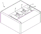
参考图5-图7,导体端子1可以包括大致长方体的壳体5,壳体5限定三个导体插入开口4,每个导体插入开口通向相应的夹紧弹簧连接。在一些实施方式中,导体插入开口4可以彼此相同。壳体5可包括大致平坦的前表面17,导体插入开口4从该前表面17延伸。导体可以沿着导体插入方向I(在图7中指定)插入导体端子1中。如将参照图17所描述的,在一些实施方式中,导体端子可以根据如下过程组装,其中每个操作杆3可以沿着垂直于方向I的方向L(在图7中指定)插入壳体5中。三个驱动元件3或操作杆3可以由壳体5支撑。在一些实施方式中,壳体5可以包括多个部分,例如下部5a和上部5b(在图5中用虚线表示和分隔)。Referring to FIGS. 5-7 , the
图8示出了单独的壳体5。壳体5可包括多个支承臂8。在一些实施方式中,可为每个操作杆3提供一组的两个支承臂8。在一些实施方式中,用于两个相邻操作杆的两个相邻支承臂8可由单批材料体形成,或由单个相邻臂8’形成。在一些实施方式中,每个支承臂8可以是或可以包括弓形部分18,弓形部分18构造成保持操作杆3的枢轴销或类似结构,使得操作杆由支承臂8支撑并可以相对于支承臂8旋转。在一些实施方式中,支承臂8可以是如壳体5的连续材料的一部分或者可以由如壳体5的连续材料形成。在其他实施方式中,支承臂8可由不同批的材料形成,或者可以与壳体5分离和连接到壳体5。FIG. 8 shows the
参考图9A和图9B,其是沿着图6中的线D-D截取的剖面图,导体端子1包括一个或多个夹紧弹簧连接,每个由夹紧弹簧2的主要部分19和母线6的相应部分在夹紧弹簧连接位置14处限定。因此,夹紧弹簧2的主要部分19可被配置为将电导体夹持到母线6。导体插入开口4可包括与壳体5的前表面17相邻的入口部分16,以及与夹紧弹簧连接位置14相邻的引入部分15。导体插入开口的引入部分15可以比入口部分16窄。引入部分15可以包括与壳体5的前表面17成非垂直的角度的一个或多个表面,如图2和图9所示。如图9A所示,入口部分16也可以与前表面17成非垂直的角度。Referring to Fig. 9A and Fig. 9B, it is the sectional view taken along the line D-D in Fig. A corresponding portion is defined at the clamping
每个导体插入开口可限定一个中心轴线C,该中心轴线C可偏离夹紧弹簧连接位置14。因此,当插入导体并将导体夹在夹紧弹簧2和母线6之间时,导体弯曲成弯曲形状,这有助于将导体保持在夹具1中。Each conductor insertion opening may define a central axis C that may be offset from the clamping
如图10所示,操作臂3可旋转至打开状态。在这种旋转下,楔形部分9可以向弹簧构件12施加力,从而使弹簧构件12和主要部分19偏转,并形成导体可以插入其中的开口28。尽管图10包括支承臂8和枢转部分10之间以及楔形部分9和弹簧构件12之间的间隙,但是在一些实施方式中,这些部件可以在打开状态下彼此齐平。As shown in Fig. 10, the
参考图11和图12,图11是沿图6中的线E-E截取的端子1的一部分的剖面图,图12是导体端子1的等轴侧视图,其中移除了壳体并具有替代的驱动元件3,每个操作杆3可以包括枢转部分10和楔形部分9。包括销或类似结构的枢转部分10可以由支承臂8支撑。楔形部分9可被配置为向弹簧构件12施加力,以便当操作杆3旋转以偏转弹簧构件12时楔入弹簧构件12和支承臂8之间。弹簧构件12可以刚性地连接有主要部分19,使得弹簧构件12的偏转可以导致主要部分19的基本相等偏转。Referring to Figures 11 and 12, Figure 11 is a cross-sectional view of a portion of the
在一些实施方式中,每个操作杆3可包括两个枢转部分10和两个楔形部分9,每个枢转部分10由各自的支承臂8支承,每个楔形部分9设置为与各自的弹簧构件12相互作用。因此,在一些实施方式中,每个夹紧弹簧连接可以与两个弹簧构件12和两个楔形部分9相关联,用于打开和关闭连接。每个操作杆3可以被配置为围绕旋转轴线R旋转。旋转轴线R可以垂直于通过导体插入开口4的导体的插入方向I。In some embodiments, each operating
如图12和图14所示,在一些实施方式中,操作杆3可以限定一个或多个绝缘壁13,用于将导体从导体插入开口4的引入部分15引导到夹紧弹簧连接位置14。当杆处于打开状态时,绝缘壁13可以设置在夹紧弹簧连接位置14的两侧(沿着平行于旋转轴线R的线)。在打开状态下,壁13可以沿着导体插入方向从楔形部分9突出。如图12所示,在闭合状态下,壁13可沿着垂直于导体插入方向的方向从楔形部分9突出。As shown in FIGS. 12 and 14 , in some embodiments the operating
参考图2、图12和图14,绝缘壁13可以设置在支承臂8和夹紧位置14之间。此外,绝缘壁13可以设置在枢转部分10和夹紧位置14之间。此外,绝缘壁13可设置在楔形部分9和夹紧位置14之间。因此,绝缘壁可防止导体插入期间导体与支承臂8、枢转部分10和/或楔形部分10之间的接触。防止这种接触可以保护导体和支承臂8、枢转部分10和/或楔形部分10。当导体是绞合线时,防止这种接触可能特别有益,相比实芯线,绞合线更容易发生线部分的转向或弯曲。Referring to FIGS. 2 , 12 and 14 , an insulating
参考图13和图14,操作杆的楔形部分9可通过间隙11与操作杆的枢转部分分离,当操作杆3在支承臂8的支撑下旋转时,支承臂8可延伸穿过间隙11。在一些实施方式中,楔形部分9、间隙11和枢转部分10可共同限定操作杆3的操作部分7。因此,在一些实施方式中,每个操作杆3可以包括两个操作部分7。每个操作部分7可以通过凹部21与操作杆的另一个操作部分分离,凹部21可以限定从导体插入开口的引入部分到夹紧弹簧连接位置的通道。在一些实施方式、例如图13的实施方式中,操作杆3可以穿过旋转轴线R的中点M对称(例如,具有镜像对称)。Referring to FIGS. 13 and 14 , the
参考图15和图16,在一些实施方式中,多个夹紧弹簧2可以由整体材料形成。每个夹紧弹簧2可包括主要部分19、两个弹簧构件12和底座部分22,主要部分和弹簧构件从底座部分22延伸。在一些实施方式中,主要部分19及其相关联的弹簧构件12可以由整体材料形成。每个主要部分19可以比其相应的弹簧构件12在导体插入方向I(图15中的方向I)上延伸得更远。此外,每个主要部分19可以比其相应的弹簧构件12在垂直于导体插入方向的朝向操作杆3的方向(在图16中指示为方向P)上延伸得更远。弹簧构件12可以设置在主要部分19的相对侧(例如,沿着平行于旋转轴线R的线相对)。Referring to Figures 15 and 16, in some embodiments the plurality of clamping
每个弹簧构件12可以是大致S形的,并且可以包括第一弯曲部分23和第二弯曲部分24,第一弯曲部分23以与主要部分19不同的角度将弹簧构件12延伸远离夹紧弹簧2的底座部分22,第二弯曲部分24提供操作杆与之相互作用的表面。每个弹簧构件12可以沿着旋转轴线R的方向通过狭槽25与主要部分19分开。此外,每个夹紧弹簧2可以沿着旋转轴线R的方向通过狭槽26与每个相邻的夹紧弹簧2分开,使得相邻的夹紧弹簧2不刚性地连接在一起,并且可以单独地偏转。Each
图17是示出组装导体端子1的示例性方法100的流程图。方法100可以包括,在框102处,提供第一下部壳体部分。第一壳体部分可以包括将成为完成的壳体的底表面的部分,并且在一些实施方式中,包括沿着将成为导体插入方向的方向延伸的一个或多个纵向通道。FIG. 17 is a flowchart illustrating an
方法100可进一步包括,在框104处,将夹紧弹簧和母线组装成夹紧弹簧连接组件。夹紧弹簧连接组件可以具有一个或多个夹紧弹簧连接(例如,如本文实施例中所示的三个夹紧弹簧连接)。The
方法100可进一步包括,在框106处,将夹紧弹簧连接组件插入第一壳体部分。在框106处,每个夹紧弹簧连接可以被放置在限定在第一壳体部分中的相应通道中。The
方法100可进一步包括,在框108处,将第二上部壳体部分连接到第一壳体部分,以将夹紧弹簧连接组件容纳在最终壳体中。壳体可以限定导体插入方向。在一些实施方式中,第二壳体部分可以包括一个或多个支承臂。在一些实施方式中,第二壳体部分可以包括将成为完成的壳体的侧壁(包括正面)和完成的壳体的顶部的部分。第二壳体部分可在其上表面中限定一个或多个孔,操作杆可通过该孔插入并且在完成的连接器中操作杆可以通过其突出。在一些实施方式中,框108可以包括将第一壳体部分点焊到第二壳体部分,或者以其他方式将第一和第二壳体部分彼此刚性地连接。The
方法100可进一步包括,在框110,将一个或多个操作杆从垂直于导体插入方向的方向插入最终的壳体。操作杆可以被插入,使得它们由壳体的支承臂支撑。框110,特别是在壳体完成之后沿着垂直于导体插入方向的方向插入操作杆,可以提供优于已知的连接器组装方法(其中操作杆通常在壳体完成之前沿着导体插入方向安装)的优点。方法100提供了比已知方法更简单的组装过程,因为壳体件不需要装配在操作杆上,并且操作杆不需要沿着导体插入方向通过其他部件插入。此外,方法100允许更换损坏的操作杆。
虽然已经详细描述了各种概念,但本领域技术人员将理解,可以根据本公开的总体教导来开发这些概念的各种改进和替代方案。另外,将理解的是,所公开的特定概念仅是说明性的,而不限制本发明的范围,本发明的范围应被赋予所附权利要求书及其任何等价物的全部广度。While various concepts have been described in detail, those skilled in the art will appreciate that various modifications and alternatives to these concepts can be developed based on the general teachings of this disclosure. Furthermore, it is to be understood that the particular concepts disclosed are illustrative only and not limiting of the scope of the invention which is to be given the full breadth of the appended claims and any equivalents thereof.
Claims (29)
Applications Claiming Priority (3)
| Application Number | Priority Date | Filing Date | Title |
|---|---|---|---|
| US202063040815P | 2020-06-18 | 2020-06-18 | |
| US63/040,815 | 2020-06-18 | ||
| PCT/US2021/038221 WO2021258043A1 (en) | 2020-06-18 | 2021-06-21 | Conductor terminal |
Publications (1)
| Publication Number | Publication Date |
|---|---|
| CN115769440A true CN115769440A (en) | 2023-03-07 |
Family
ID=79025360
Family Applications (1)
| Application Number | Title | Priority Date | Filing Date |
|---|---|---|---|
| CN202180043688.XA Pending CN115769440A (en) | 2020-06-18 | 2021-06-21 | Conductor terminal |
Country Status (6)
| Country | Link |
|---|---|
| US (2) | US12176651B2 (en) |
| EP (1) | EP4169128A4 (en) |
| CN (1) | CN115769440A (en) |
| AU (3) | AU2021292753B2 (en) |
| MX (1) | MX2022015904A (en) |
| WO (1) | WO2021258043A1 (en) |
Families Citing this family (1)
| Publication number | Priority date | Publication date | Assignee | Title |
|---|---|---|---|---|
| EP4544643A1 (en) * | 2022-06-27 | 2025-04-30 | Ideal Industries Inc. | Lever connector for electrical conductors |
Family Cites Families (79)
| Publication number | Priority date | Publication date | Assignee | Title |
|---|---|---|---|---|
| FR2393448A1 (en) | 1976-08-18 | 1978-12-29 | Wago Kontakttechnik Gmbh | ELECTRICAL CONNECTION OR CONNECTION DEVICE |
| DE3805158A1 (en) | 1988-02-15 | 1989-08-24 | Wago Verwaltungs Gmbh | SERIES TERMINAL FOR THE TWO-WIRE POWER SUPPLY OF ELECTRICAL OR ELECTRONIC COMPONENTS, IN PARTICULAR INITIATORS |
| US5015974A (en) | 1988-06-20 | 1991-05-14 | Oki Electric Industry Co., Ltd. | Isolating circuit and dielectric filter for use therein |
| DE3903752A1 (en) | 1989-02-06 | 1990-08-09 | Wago Verwaltungs Gmbh | PROTECTIVE LADDER TERMINAL |
| DE3910937C2 (en) | 1989-04-01 | 1995-03-09 | Wago Verwaltungs Gmbh | Add-on terminal block for printed circuit boards |
| DE19603960B4 (en) | 1996-01-26 | 2008-03-06 | Wago Verwaltungsgesellschaft Mbh | Multipole branch connector |
| DE19641206C2 (en) | 1996-09-25 | 1999-12-23 | Wago Verwaltungs Gmbh | Terminal for electrical conductors |
| US6074241A (en) | 1998-06-05 | 2000-06-13 | The Whitaker Corporation | Non-slip spring clamp contact |
| DE10239273A1 (en) | 2002-08-22 | 2004-03-04 | Wago Verwaltungsgesellschaft Mbh | Spring clamp connection for an electrical conductor |
| DE102004018554B4 (en) | 2004-04-14 | 2018-09-27 | Wago Verwaltungsgesellschaft Mbh | Jumper for electrical terminals |
| DE102004037997A1 (en) | 2004-08-04 | 2006-03-16 | Wago Verwaltungsgesellschaft Mbh | Electrical branch connection connector |
| DE202005018168U1 (en) | 2005-11-22 | 2006-01-12 | Phoenix Contact Gmbh & Co. Kg | Conductor spring clamp containing housing with clamping position(s) formed by clamping shank of spring and clamping counterbearing adjacent to clamping shank end |
| DE102006018129C5 (en) | 2006-04-19 | 2013-04-11 | Phoenix Contact Gmbh & Co. Kg | Spring terminal with a leg spring arranged in a housing |
| TWI449281B (en) | 2006-04-25 | 2014-08-11 | Wago Verwaltungs Gmbh | Electronic connector |
| DE102007017593B4 (en) | 2006-04-28 | 2011-07-21 | WAGO Verwaltungsgesellschaft mbH, 32423 | Electrical connection and connection terminal |
| DE102007022806B3 (en) | 2007-05-11 | 2008-11-27 | Wago Verwaltungsgesellschaft Mbh | clamping member |
| DE102007051900B4 (en) | 2007-10-29 | 2009-09-10 | Wago Verwaltungsgesellschaft Mbh | Spring connection |
| WO2009124662A1 (en) | 2008-04-08 | 2009-10-15 | Wago Verwaltungsgesellschaft Mbh | Connection adapter/terminal set and corresponding connection adapter and terminal |
| DE102008039868A1 (en) | 2008-08-27 | 2010-03-04 | Phoenix Contact Gmbh & Co. Kg | Electrical connection terminal |
| DE102009030645B4 (en) | 2009-06-25 | 2011-09-01 | Wago Verwaltungsgesellschaft Mbh | Brückerelement and set of at least one clamping element and Brückerelement |
| DE202009009066U1 (en) | 2009-06-30 | 2009-09-03 | Wago Verwaltungsgesellschaft Mbh | automation equipment |
| DE102009035716B4 (en) | 2009-07-31 | 2014-03-27 | Wago Verwaltungsgesellschaft Mbh | Connectors |
| DE102010014143B4 (en) | 2010-04-07 | 2016-07-07 | Wago Verwaltungsgesellschaft Mbh | Actuation device for an electrical connection terminal |
| DE102010023423A1 (en) | 2010-06-11 | 2011-12-15 | Wago Verwaltungsgesellschaft Mbh | Spring clamp and terminal block |
| DE102010045913B4 (en) | 2010-09-21 | 2012-05-24 | Wago Verwaltungsgesellschaft Mbh | Wall bushing connector and fastener for this purpose |
| DE102011016458A1 (en) | 2011-04-08 | 2012-10-11 | Wago Verwaltungsgesellschaft Mbh | Conductor connector, connector and set of conductor connector and connector |
| DE102011106853A1 (en) | 2011-07-05 | 2013-01-10 | Wago Verwaltungsgesellschaft Mbh | Built-in connector |
| DE102011056410B4 (en) | 2011-12-14 | 2013-06-27 | Wago Verwaltungsgesellschaft Mbh | terminal |
| DE102011056986A1 (en) | 2011-12-23 | 2013-06-27 | Wago Verwaltungsgesellschaft Mbh | Conductor terminal |
| DE102012103216A1 (en) | 2012-04-13 | 2013-10-17 | Wago Verwaltungsgesellschaft Mbh | Connector set and connectors and mating connector this |
| DE202012102325U1 (en) | 2012-06-25 | 2012-07-17 | Wago Verwaltungsgesellschaft Mbh | Electronic equipment housing |
| DE102012105508B4 (en) | 2012-06-25 | 2016-11-10 | Wago Verwaltungsgesellschaft Mbh | Pin contact element and electronics housing |
| DE102012110759B4 (en) | 2012-11-09 | 2021-04-01 | Wago Verwaltungsgesellschaft Mbh | Spring clamp connection and electrical device herewith |
| DE102013101406B4 (en) | 2013-02-13 | 2018-07-12 | Wago Verwaltungsgesellschaft Mbh | Conductor terminal |
| DE102013101409B4 (en) | 2013-02-13 | 2022-01-20 | Wago Verwaltungsgesellschaft Mbh | conductor terminal |
| DE202013100635U1 (en) | 2013-02-13 | 2013-03-04 | Wago Verwaltungsgesellschaft Mbh | Spring terminal and connection terminal for electrical conductors |
| DE102013101411B4 (en) | 2013-02-13 | 2018-03-22 | Wago Verwaltungsgesellschaft Mbh | Spring terminal connection and conductor terminal |
| DE102013103658B4 (en) | 2013-04-11 | 2014-10-23 | Wago Verwaltungsgesellschaft Mbh | Conductor terminal |
| DE202013101582U1 (en) * | 2013-04-15 | 2014-07-16 | Weidmüller Interface GmbH & Co. KG | Spring-loaded clamping element with pivoting lever |
| DE102013111574B4 (en) | 2013-10-21 | 2017-01-12 | Wago Verwaltungsgesellschaft Mbh | Spring terminal and connector |
| DE102013111578B4 (en) | 2013-10-21 | 2019-04-18 | Wago Verwaltungsgesellschaft Mbh | electronic module |
| DE102014102517B4 (en) | 2014-02-26 | 2021-06-10 | Wago Verwaltungsgesellschaft Mbh | Connecting terminal and spring-loaded terminal contact for this |
| DE102014103059B4 (en) | 2014-03-07 | 2024-12-05 | Wago Verwaltungsgesellschaft Mbh | terminal block arrangement |
| ES2662873T3 (en) * | 2014-05-23 | 2018-04-10 | Berker Gmbh & Co. Kg | Connection terminals with spring-loaded clamping |
| DE102014107948B3 (en) | 2014-06-05 | 2015-07-30 | Wago Verwaltungsgesellschaft Mbh | Connector assembly and coding element and method for encoding a connector assembly |
| DE102014114026B4 (en) * | 2014-09-26 | 2023-03-30 | Wago Verwaltungsgesellschaft Mbh | Conductor terminal and method of assembly |
| DE102014114352B3 (en) | 2014-10-02 | 2016-03-10 | Wago Verwaltungsgesellschaft Mbh | pin header |
| DE102014119420B3 (en) | 2014-12-22 | 2016-05-12 | Wago Verwaltungsgesellschaft Mbh | terminal |
| DE102014119421B4 (en) | 2014-12-22 | 2017-02-02 | Wago Verwaltungsgesellschaft Mbh | Connection terminal and method for mounting a connection terminal |
| CN204558667U (en) | 2015-04-11 | 2015-08-12 | 江门市创艺电器有限公司 | A kind of terminal connector |
| DE102015107055B3 (en) | 2015-05-06 | 2016-10-06 | Wago Verwaltungsgesellschaft Mbh | Conductor terminal |
| DE102015107853B4 (en) | 2015-05-19 | 2020-08-13 | Wago Verwaltungsgesellschaft Mbh | Conductor connection terminal |
| DE202015103779U1 (en) | 2015-07-17 | 2016-10-18 | Wago Verwaltungsgesellschaft Mbh | Connectors |
| DE102015119247B4 (en) * | 2015-11-09 | 2026-03-19 | Wago Verwaltungsgesellschaft Mbh | Connection terminal |
| DE202016106235U1 (en) | 2015-12-02 | 2017-03-03 | Wago Verwaltungsgesellschaft Mbh | Conductor connection contact and circuit board arrangement |
| DE102015122143B4 (en) | 2015-12-17 | 2019-02-14 | Wago Verwaltungsgesellschaft Mbh | Conductor terminal |
| DE202016100323U1 (en) | 2016-01-25 | 2017-04-28 | Wago Verwaltungsgesellschaft Mbh | Cross connector for terminal blocks |
| DE102016101621B4 (en) | 2016-01-29 | 2018-10-18 | Wago Verwaltungsgesellschaft Mbh | Housing for an electrical connector |
| DE102016111627A1 (en) * | 2016-06-24 | 2017-12-28 | Wago Verwaltungsgesellschaft Mbh | Conductor terminal |
| DE102016122238A1 (en) | 2016-11-18 | 2018-05-24 | Wago Verwaltungsgesellschaft Mbh | Spring terminal contact for contacting electrical conductors, conductor terminal and method for producing a spring terminal contact |
| DE102017117179B4 (en) | 2017-07-28 | 2020-03-26 | Wago Verwaltungsgesellschaft Mbh | Device arrangement |
| DE102017125270B3 (en) | 2017-10-27 | 2019-03-21 | Wago Verwaltungsgesellschaft Mbh | Abgriffsteckverbinder |
| DE102018102011B4 (en) | 2018-01-30 | 2020-07-02 | Wago Verwaltungsgesellschaft Mbh | Electrical connector |
| DE102018116665A1 (en) | 2018-07-10 | 2020-01-16 | Wago Verwaltungsgesellschaft Mbh | Conductor terminal |
| DE102018117508B4 (en) * | 2018-07-19 | 2024-01-18 | Wago Verwaltungsgesellschaft Mbh | Conductor connection terminal |
| CN112823293B (en) | 2018-10-04 | 2024-12-06 | ams有限公司 | High-resolution time-of-flight measurements |
| DE102018124623B4 (en) | 2018-10-05 | 2022-07-07 | Wago Verwaltungsgesellschaft Mbh | Contact insert of a conductor terminal and conductor terminal formed therewith |
| DE202018004944U1 (en) | 2018-10-25 | 2020-01-28 | Electro Terminal Gmbh & Co Kg | Series plug-in terminal |
| US10418727B1 (en) | 2018-11-15 | 2019-09-17 | Dinkle Enterprise Co., Ltd. | Rotate-to-open clamping unit and connection device having the same |
| DE202018106899U1 (en) | 2018-12-04 | 2020-03-05 | WAGO Verwaltungsgesellschaft mit beschränkter Haftung | Spring terminal |
| DE102018131794B4 (en) | 2018-12-11 | 2023-06-01 | Wago Verwaltungsgesellschaft Mbh | conductor terminal |
| DE102019101880B4 (en) | 2019-01-25 | 2023-09-14 | Wago Verwaltungsgesellschaft Mbh | Clamping spring and conductor connection terminal |
| JP7653769B2 (en) | 2019-04-30 | 2025-03-31 | ヴァーゴ・フェアヴァルトゥングスゲゼルシャフト・エムベーハー | Connector for an electrical connector assembly and electrical connector assembly formed thereby - Patents.com |
| DE102019111164A1 (en) | 2019-04-30 | 2020-11-05 | Wago Verwaltungsgesellschaft Mbh | Plug connector of an electrical connector and a set of plug connector and functional element |
| DE102019119252B3 (en) | 2019-07-16 | 2020-10-08 | Wago Verwaltungsgesellschaft Mbh | Connector for power supply profiles with inserted electrical conductors with continuous tapping option |
| DE202019105009U1 (en) * | 2019-09-11 | 2020-12-14 | Wago Verwaltungsgesellschaft Mbh | Conductor connection terminal |
| DE102020102605B3 (en) | 2020-02-03 | 2021-06-10 | WAGO Verwaltungsgesellschaft mit beschränkter Haftung | Contact insert |
| TWI732639B (en) * | 2020-07-29 | 2021-07-01 | 金筆企業股份有限公司 | Electrical conductor connector |
| DE202020105715U1 (en) | 2020-10-06 | 2022-01-10 | Electro Terminal GmbH & Co. KG | Clamp with release lever |
-
2021
- 2021-06-21 MX MX2022015904A patent/MX2022015904A/en unknown
- 2021-06-21 WO PCT/US2021/038221 patent/WO2021258043A1/en not_active Ceased
- 2021-06-21 US US17/905,401 patent/US12176651B2/en active Active
- 2021-06-21 CN CN202180043688.XA patent/CN115769440A/en active Pending
- 2021-06-21 EP EP21825501.6A patent/EP4169128A4/en active Pending
- 2021-06-21 AU AU2021292753A patent/AU2021292753B2/en active Active
-
2024
- 2024-03-20 AU AU2024201817A patent/AU2024201817A1/en not_active Abandoned
- 2024-12-23 US US18/999,084 patent/US20250125560A1/en active Pending
-
2025
- 2025-11-18 AU AU2025270964A patent/AU2025270964A1/en active Pending
Also Published As
| Publication number | Publication date |
|---|---|
| EP4169128A4 (en) | 2024-07-03 |
| EP4169128A1 (en) | 2023-04-26 |
| US12176651B2 (en) | 2024-12-24 |
| WO2021258043A1 (en) | 2021-12-23 |
| AU2025270964A1 (en) | 2025-12-11 |
| US20250125560A1 (en) | 2025-04-17 |
| AU2021292753B2 (en) | 2023-12-21 |
| CA3187568A1 (en) | 2021-12-23 |
| US20230123609A1 (en) | 2023-04-20 |
| AU2021292753A1 (en) | 2023-02-02 |
| MX2022015904A (en) | 2023-01-24 |
| AU2024201817A1 (en) | 2024-04-11 |
Similar Documents
| Publication | Publication Date | Title |
|---|---|---|
| US4084876A (en) | Electrical connector | |
| US6814608B2 (en) | Spring-force clamp connector for an electrical conductor | |
| JP7429218B2 (en) | conductor connection clamp | |
| CN207938828U (en) | wire connection clip | |
| TWI356543B (en) | ||
| CN114389070A (en) | Terminal with release lever | |
| AU2025270964A1 (en) | Conductor terminal | |
| CN101924293A (en) | Online inserting type conductive wire connector | |
| JP2014154556A (en) | Electrical connection device with spring connection member with small-sized actuator and multipolar connector with contact of multiple springs | |
| CN113871904B (en) | Electrical terminal clamps | |
| CN113169464B (en) | Spring terminal blocks | |
| CN112490695A (en) | Connecting terminal | |
| CN1069450C (en) | Connector for electric cable | |
| JPH0626150B2 (en) | Electric wire automatic exposure connector | |
| JPH06231812A (en) | Assembly type electric contact and electric connector using it | |
| US6966793B2 (en) | Electrical connector having a cover for registering cables with contacts | |
| CA3187568C (en) | Conductor terminal | |
| JPH11260434A (en) | Connection device having elastic frame | |
| CN114336148A (en) | Retaining frame for plug-in connectors | |
| JP4299919B2 (en) | Terminal block | |
| JPS6028111B2 (en) | Cross connection assembly for communication wires | |
| JP2002343487A (en) | Electrical connector | |
| KR20240039035A (en) | Automatic connection terminal and associated switchgear device with two contact zones | |
| US20260051674A1 (en) | Conductor connection terminal | |
| US12300913B2 (en) | Terminal with release lever |
Legal Events
| Date | Code | Title | Description |
|---|---|---|---|
| PB01 | Publication | ||
| PB01 | Publication | ||
| SE01 | Entry into force of request for substantive examination | ||
| SE01 | Entry into force of request for substantive examination |