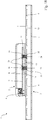
DE102017117179B4 - Device arrangement - Google Patents

Device arrangement Download PDF

Info

Publication number
DE102017117179B4
DE102017117179B4 DE102017117179.7A DE102017117179A DE102017117179B4 DE 102017117179 B4 DE102017117179 B4 DE 102017117179B4 DE 102017117179 A DE102017117179 A DE 102017117179A DE 102017117179 B4 DE102017117179 B4 DE 102017117179B4
Authority
DE
Germany
Prior art keywords
contact
circuit board
printed circuit
contact element
spring
Prior art date
Legal status (The legal status is an assumption and is not a legal conclusion. Google has not performed a legal analysis and makes no representation as to the accuracy of the status listed.)
Expired - Fee Related
Application number
DE102017117179.7A
Other languages
German (de)
Other versions
DE102017117179A1 (en
Inventor
Stephan Gassauer
Thomas Trümper
Current Assignee (The listed assignees may be inaccurate. Google has not performed a legal analysis and makes no representation or warranty as to the accuracy of the list.)
Wago Verwaltungs GmbH
Original Assignee
Wago Verwaltungs GmbH
Priority date (The priority date is an assumption and is not a legal conclusion. Google has not performed a legal analysis and makes no representation as to the accuracy of the date listed.)
Filing date
Publication date
Application filed by Wago Verwaltungs GmbH filed Critical Wago Verwaltungs GmbH
Priority to DE102017117179.7A priority Critical patent/DE102017117179B4/en
Priority to CN201821184601.2U priority patent/CN209150334U/en
Priority to EP18185926.5A priority patent/EP3435488B1/en
Publication of DE102017117179A1 publication Critical patent/DE102017117179A1/en
Application granted granted Critical
Publication of DE102017117179B4 publication Critical patent/DE102017117179B4/en
Expired - Fee Related legal-status Critical Current
Anticipated expiration legal-status Critical

Links

Images

Classifications

    • HELECTRICITY
    • H01ELECTRIC ELEMENTS
    • H01RELECTRICALLY-CONDUCTIVE CONNECTIONS; STRUCTURAL ASSOCIATIONS OF A PLURALITY OF MUTUALLY-INSULATED ELECTRICAL CONNECTING ELEMENTS; COUPLING DEVICES; CURRENT COLLECTORS
    • H01R12/00Structural associations of a plurality of mutually-insulated electrical connecting elements, specially adapted for printed circuits, e.g. printed circuit boards [PCB], flat or ribbon cables, or like generally planar structures, e.g. terminal strips, terminal blocks; Coupling devices specially adapted for printed circuits, flat or ribbon cables, or like generally planar structures; Terminals specially adapted for contact with, or insertion into, printed circuits, flat or ribbon cables, or like generally planar structures
    • H01R12/70Coupling devices
    • H01R12/71Coupling devices for rigid printing circuits or like structures
    • H01R12/712Coupling devices for rigid printing circuits or like structures co-operating with the surface of the printed circuit or with a coupling device exclusively provided on the surface of the printed circuit
    • H01R12/716Coupling device provided on the PCB
    • H01R12/718Contact members provided on the PCB without an insulating housing
    • HELECTRICITY
    • H01ELECTRIC ELEMENTS
    • H01RELECTRICALLY-CONDUCTIVE CONNECTIONS; STRUCTURAL ASSOCIATIONS OF A PLURALITY OF MUTUALLY-INSULATED ELECTRICAL CONNECTING ELEMENTS; COUPLING DEVICES; CURRENT COLLECTORS
    • H01R12/00Structural associations of a plurality of mutually-insulated electrical connecting elements, specially adapted for printed circuits, e.g. printed circuit boards [PCB], flat or ribbon cables, or like generally planar structures, e.g. terminal strips, terminal blocks; Coupling devices specially adapted for printed circuits, flat or ribbon cables, or like generally planar structures; Terminals specially adapted for contact with, or insertion into, printed circuits, flat or ribbon cables, or like generally planar structures
    • H01R12/50Fixed connections
    • H01R12/51Fixed connections for rigid printed circuits or like structures
    • H01R12/52Fixed connections for rigid printed circuits or like structures connecting to other rigid printed circuits or like structures
    • H01R12/523Fixed connections for rigid printed circuits or like structures connecting to other rigid printed circuits or like structures by an interconnection through aligned holes in the boards or multilayer board
    • HELECTRICITY
    • H01ELECTRIC ELEMENTS
    • H01RELECTRICALLY-CONDUCTIVE CONNECTIONS; STRUCTURAL ASSOCIATIONS OF A PLURALITY OF MUTUALLY-INSULATED ELECTRICAL CONNECTING ELEMENTS; COUPLING DEVICES; CURRENT COLLECTORS
    • H01R12/00Structural associations of a plurality of mutually-insulated electrical connecting elements, specially adapted for printed circuits, e.g. printed circuit boards [PCB], flat or ribbon cables, or like generally planar structures, e.g. terminal strips, terminal blocks; Coupling devices specially adapted for printed circuits, flat or ribbon cables, or like generally planar structures; Terminals specially adapted for contact with, or insertion into, printed circuits, flat or ribbon cables, or like generally planar structures
    • H01R12/50Fixed connections
    • H01R12/51Fixed connections for rigid printed circuits or like structures
    • H01R12/55Fixed connections for rigid printed circuits or like structures characterised by the terminals
    • H01R12/58Fixed connections for rigid printed circuits or like structures characterised by the terminals terminals for insertion into holes
    • HELECTRICITY
    • H01ELECTRIC ELEMENTS
    • H01RELECTRICALLY-CONDUCTIVE CONNECTIONS; STRUCTURAL ASSOCIATIONS OF A PLURALITY OF MUTUALLY-INSULATED ELECTRICAL CONNECTING ELEMENTS; COUPLING DEVICES; CURRENT COLLECTORS
    • H01R13/00Details of coupling devices of the kinds covered by groups H01R12/70 or H01R24/00 - H01R33/00
    • H01R13/02Contact members
    • H01R13/22Contacts for co-operating by abutting
    • H01R13/24Contacts for co-operating by abutting resilient; resiliently-mounted
    • H01R13/2407Contacts for co-operating by abutting resilient; resiliently-mounted characterized by the resilient means
    • H01R13/2421Contacts for co-operating by abutting resilient; resiliently-mounted characterized by the resilient means using coil springs
    • HELECTRICITY
    • H01ELECTRIC ELEMENTS
    • H01RELECTRICALLY-CONDUCTIVE CONNECTIONS; STRUCTURAL ASSOCIATIONS OF A PLURALITY OF MUTUALLY-INSULATED ELECTRICAL CONNECTING ELEMENTS; COUPLING DEVICES; CURRENT COLLECTORS
    • H01R33/00Coupling devices specially adapted for supporting apparatus and having one part acting as a holder providing support and electrical connection via a counterpart which is structurally associated with the apparatus, e.g. lamp holders; Separate parts thereof
    • H01R33/965Dustproof, splashproof, drip-proof, waterproof, or flameproof holders

Landscapes

  • Coupling Device And Connection With Printed Circuit (AREA)

Abstract

Geräteanordnung (1) mit einem ersten Geräteteil (2), in dem eine erste Leiterplatte (9) angeordnet ist, und einem zweiten Geräteteil (3), in dem eine zweite Leiterplatte (6) angeordnet ist, wobei das erste und zweite Geräteteil (2, 3) zur flächigen Anordnung aufeinander ausgebildet sind und wobei die erste und zweite Leiterplatte (9, 6) zwei voneinander beabstandete Lagen bilden, wenn das erste und zweite Geräteteil (2, 3) flächig aufeinander angeordnet sind, und sich zumindest eine Wandung eines Gerätegehäuses (8, 5) eines der beiden Geräteteile (2, 3) zwischen der ersten und zweiten Leiterplatte (9, 6) befindet dadurch gekennzeichnet,- dass die erste und zweite Leiterplatte (9, 6) Kontaktbereiche hat, und- dass ein drittes Kontaktelement (15, 28) vorgesehen ist, das mit einem Kontaktbereich der ersten Leiterplatte (9) mittelbar über ein erstes Kontaktelement (11, 29) und mit einem Kontaktbereich der zweiten Leiterplatte (6) unmittelbar oder mittelbar über ein zweites Kontaktelement (14) elektrisch leitend verbindbar ist,- wobei das dritte Kontaktelement (15, 28) die zumindest eine Wandung durchgreift.Device arrangement (1) with a first device part (2), in which a first circuit board (9) is arranged, and a second device part (3), in which a second circuit board (6) is arranged, the first and second device parts (2 , 3) are configured for a flat arrangement on top of one another and the first and second printed circuit boards (9, 6) form two spaced apart layers when the first and second device parts (2, 3) are arranged flat on top of one another, and there is at least one wall of a device housing (8, 5) one of the two device parts (2, 3) between the first and second printed circuit boards (9, 6) is characterized in that - that the first and second printed circuit boards (9, 6) have contact areas, and - that a third contact element (15, 28) is provided, which with a contact area of the first circuit board (9) indirectly via a first contact element (11, 29) and with a contact area of the second circuit board (6) directly or indirectly via a second contact Act element (14) can be electrically conductively connected, - the third contact element (15, 28) reaching through the at least one wall.

Description

Die Erfindung betrifft eine Geräteanordnung mit einem ersten Geräteteil, in dem eine erste Leiterplatte angeordnet ist, und mit einem zweiten Geräteteil, in dem eine zweite Leiterplatte angeordnet ist, wobei das erste und zweite Geräteteil zur flächigen Anordnung aufeinander ausgebildet sind, und wobei die erste und die zweite Leiterplatte zwei voneinander beabstandete Lagen bilden, wenn das erste und zweite Geräteteil flächig aufeinander angeordnet sind. Zwischen der ersten und zweiten Lage befindet sich mindestens eine Wandung eines Gerätegehäuses eines der beiden Geräteteile.The invention relates to a device arrangement with a first device part, in which a first printed circuit board is arranged, and with a second device part, in which a second printed circuit board is arranged, the first and second device parts being designed for flat arrangement on one another, and wherein the first and the second circuit board form two spaced-apart layers when the first and second device parts are arranged flat on one another. At least one wall of a device housing of one of the two device parts is located between the first and second position.

Eine solche Geräteanordnung ist beispielsweise eine Leuchte als zweites Geräteteil mit einer Leuchtelement tragenden Leiterplatte. Solche Leuchtelemente können beispielsweise Leuchtdioden (LEDs oder OLEDs) sein. Das erste Geräteteil kann ein elektronisches Anschaltgerät für eine solche LED-Leuchte sein, das eine Leiterplatte mit elektronischen Bauteilen zur Ansteuerung der Leuchtelemente in einem Anschaltgerätegehäuse hat. Das elektronische Anschaltgeräteteil wird flächig auf das Leuchtengehäuse des zweiten Geräteteils aufgelegt und mit diesem verbunden. Die elektrisch leitende Verbindung der beiden Leiterplatten des ersten und zweiten Geräteteils und der auf der Leiterplatte angeordneten elektronischen Bauelemente erfolgt herkömmlicherweise mit Leitungen, die aus an dem Geräteteil herausragen und an den Steckverbinder oder der Anschlussklemme des anderen Geräteteils angeklemmt werden.Such a device arrangement is, for example, a lamp as a second device part with a circuit board carrying a lighting element. Such lighting elements can be light-emitting diodes (LEDs or OLEDs), for example. The first device part can be an electronic connecting device for such an LED light, which has a printed circuit board with electronic components for controlling the lighting elements in a connecting device housing. The electronic control device part is placed flat on the luminaire housing of the second device part and connected to it. The electrically conductive connection of the two circuit boards of the first and second parts of the device and the electronic components arranged on the circuit board is conventionally carried out using lines which protrude from the device part and are clamped to the plug connector or the connecting terminal of the other device part.

DE 10 2011 103 738 B4 zeigt einen Verbinder mit endseitigen Stiftkontaktabschnitten, die in Federklemmanschlüsse zweier auf verschiedenen Leiterplatten angeordneten Steckverbindern eingesteckt werden. Der Verbinder hat einen mäanderförmigen Längenausgleichsbereich, durch den eine Abstandsänderung der nebeneinander auf derselben Ebene angeordneten Leiterplatten zueinander ausgeglichen werden kann. DE 10 2011 103 738 B4 shows a connector with end pin contact sections, which are inserted into spring terminals of two connectors arranged on different circuit boards. The connector has a meandering length compensation area, by means of which a change in the distance between the printed circuit boards arranged next to one another on the same plane can be compensated for.

US 7 841 864 B2 zeigt ein mehrteilig aufgebautes Kontaktelement mit endseitigen Kontaktspitzen, die an zwei zueinander verschieblich gehaltenen Kontaktteilen angeordnet sind. Zwischen den Kontaktteilen ist eine zylindrische Druckfeder positioniert, um eine Kontaktkraft aufzubauen und Längenänderungen auszugleichen. US 7 841 864 B2 shows a multi-part contact element with end contact tips, which are arranged on two mutually displaceable contact parts. A cylindrical compression spring is positioned between the contact parts in order to build up a contact force and compensate for changes in length.

EP 2 814 116 A1 zeigt eine Verbindung von zwei parallel zueinander und im Abstand voneinander angeordneten Leiterplatten mit einem metallischen Verbindungselement. Auf der Seite der ersten Leiterplatte, die von der gegenüberliegenden zweiten Leiterplatte abgewandt ist, befindet sich ein Steckkontaktelement mit Federkontaktarmen, das an die Leiterplatte angelötet ist. Das Verbindungselement durchgreift mit einem Kontaktstiftabschnitt eine Öffnung der ersten Leiterplatte und wird an die Federkontaktarme des Kontaktelementes elektrisch leitend angeklemmt. Der gegenüberliegende zweite Kontaktabschnitt des Verbindungselementes ist als federelastisch aufgeweiteter Klemmfederabschnitt ausgebildet, der klemmend und elektrisch kontaktierend in eine Kontaktbohrung der zweiten Leiterplatte eintaucht. EP 2 814 116 A1 shows a connection of two circuit boards arranged parallel to one another and at a distance from one another with a metallic connecting element. On the side of the first printed circuit board, which faces away from the opposite second printed circuit board, there is a plug contact element with spring contact arms, which is soldered to the printed circuit board. The connecting element passes through an opening in the first printed circuit board with a contact pin section and is clamped in an electrically conductive manner to the spring contact arms of the contact element. The opposite second contact section of the connecting element is designed as a spring-elastically widened clamping spring section, which, in a clamping and electrically contacting manner, plunges into a contact hole in the second printed circuit board.

US 5 192 232 A beschreibt ein elektrisches Verbindersystem mit einer ersten Verbinderanordnung mit einem Isolierstoffgehäuse, das einen Hohlraum mit einem dünnen männlichen Steckverbinder hat. Weiter ist eine zweite Verbinderanordnung mit einem Isolierstoffgehäuse vorgesehen, dass einen Hohlraum mit einem Federkontaktanschluss zur Steckkontaktierung des männlichen Steckverbinders hat. Die beiden Verbinderanordnungen sind auf Leiterplatten auflötbar. US 5 192 232 A describes an electrical connector system having a first connector assembly with an insulating housing that has a cavity with a thin male connector. Furthermore, a second connector arrangement with an insulating material housing is provided, which has a cavity with a spring contact connection for plug-in contacting of the male connector. The two connector arrangements can be soldered onto printed circuit boards.

Ausgehend hiervon ist es Aufgabe der vorliegenden Erfindung eine Geräteanordnung mit einem ersten und zweiten Geräteteil zu schaffen, die beim Aufsetzen aufeinander schnell und sicher elektrisch leitend miteinander kontaktiert werden und die elektrische Verbindung vor Umwelteinflüssen weitestgehend geschützt wird.Proceeding from this, it is an object of the present invention to provide a device arrangement with a first and a second device part which, when placed one on top of the other, are quickly and safely contacted in an electrically conductive manner and the electrical connection is largely protected from environmental influences.

Unter Umwelteinflüssen sind Einflüsse durch Eindringen von Staub, Feuchtigkeit und/oder einem Berührschutz oder ähnliches zu verstehen, wenn das erste und zweite Gehäuseteil flächig aufeinander liegen.Environmental influences are to be understood as influences due to the penetration of dust, moisture and / or contact protection or the like if the first and second housing parts lie flat on one another.

Die Aufgabe wird mit der Geräteanordnung nach Anspruch 1 gelöst. Vorteilhafte Ausführungsformen sind in den Unteransprüchen beschrieben.The object is achieved with the device arrangement according to claim 1. Advantageous embodiments are described in the subclaims.

Es wird vorgeschlagen, dass die erste und zweite Leiterplatte Kontaktbereiche hat, und dass ein drittes Kontaktelement vorgesehen ist, das mit einem Kontaktbereich der ersten Leiterplatte mittelbar über ein erstes Kontaktelement und mit einem Kontaktbereich der zweiten Leiterplatte unmittelbar oder mittelbar über ein zweites Kontaktelement elektrisch leitend verbindbar ist, wobei das dritte Kontaktelement die zumindest eine Wandung durchgreift.It is proposed that the first and second printed circuit boards have contact areas, and that a third contact element is provided which can be electrically conductively connected to a contact area of the first printed circuit board indirectly via a first contact element and to a contact area of the second printed circuit board directly or indirectly via a second contact element is, wherein the third contact element passes through the at least one wall.

Die in dem ersten und zweiten Geräteteil angeordneten ersten und zweiten Leiterplatten werden somit durch mindestens ein drittes Kontaktelement elektrisch leitend miteinander verbunden, das mittelbar über ein erstes Kontaktelement mit einem jeweiligen Kontaktbereich der ersten Leiterplatte verbindbar und unmittelbar mit dem jeweiligen Kontaktbereich der zweiten Leiterplatte oder mittelbar über ein zweites Kontaktelement mit dem jeweiligen Kontaktbereich der zweiten Leiterplatte verbindbar ist. Das Kontaktelement erstreckt sich dabei von den auf parallelen Ebenen im Abstand voneinander angeordneten ersten und zweiten Leiterplatten und steht dabei in der Regel im Wesentlichen lotrecht zu den Leiterplatten. Das bedingt, dass die Steckrichtung des mindestens einen Kontaktelementes nicht parallel zur Ebene der Leiterplatten ausgerichtet ist, sondern eher quer zu den Ebenen der Leiterplatten. Über die Kontaktflächen der Leiterplatten, das mit einer Kontaktfläche der ersten Leiterplatte verbundene erste Kontaktelement und das dritte Kontaktelement sowie ggf. ein mit der Kontaktfläche der zweiten Leiterplatte verbundenes zweites Kontaktelement wird eine elektrisch leitende Verbindung zwischen zwei einander zugeordneten Kontaktbereichen der beiden Leiterplatten hergestellt. Das dritte Kontaktelement durchgreift dabei eine Wandung eines Gerätegehäuses, die sich zwischen der ersten und zweiten Leiterplatte befindet. Damit wird die Ausrichtung und Positionierung der beiden Geräteteile zueinander für das Aufeinanderstecken besser erkennbar und die Luft- und Kriechstecken werden optimiert.The first and second printed circuit boards arranged in the first and second device parts are thus electrically conductively connected to one another by at least a third contact element, which can be connected indirectly to a respective contact area of the first printed circuit board via a first contact element and directly to the respective contact area of the second printed circuit board or indirectly via a second contact element can be connected to the respective contact area of the second printed circuit board. The The contact element extends from the first and second printed circuit boards spaced apart on parallel planes and is generally essentially perpendicular to the printed circuit boards. This means that the direction of insertion of the at least one contact element is not aligned parallel to the level of the printed circuit boards, but rather transversely to the levels of the printed circuit boards. An electrically conductive connection is established between two mutually associated contact areas of the two printed circuit boards via the contact surfaces of the printed circuit boards, the first contact element connected to a contact surface of the first printed circuit board and the third contact element and possibly a second contact element connected to the contact surface of the second printed circuit board. The third contact element passes through a wall of a device housing, which is located between the first and second printed circuit boards. This makes it easier to see the alignment and positioning of the two parts of the device in relation to one another when plugged together, and the air and crawl spaces are optimized.

Das mindestens eine relativ zueinander positionierte Paar von Kontaktbereichen der ersten und zweiten Leiterplatte mit dem dazwischenliegenden dritten Kontaktelement hat den Vorteil, dass das erste Geräteteil flächig auf das zweite Geräteteil aufgesetzt werden kann und dabei gleichzeitig über das dritte Kontaktelement der elektrisch leitende Kontakt hergestellt wird. Das Kontaktelement befindet sich dann zwangsläufig in dem vom ersten und zweiten Geräteteil abgedeckten Bereich und ist damit unzugänglich. Damit wird nicht nur ein Berührschutz erreicht, sondern dass die elektrisch leitende Verbindung durch die flächige Auflage des ersten und zweiten Geräteteils auch vor weiteren Umwelteinflüssen wie Staub und gegebenenfalls Feuchtigkeit geschützt ist. Damit wird auch vorteilhaft eine kompakte und wenig Bauraum beanspruchende Anordnung der Gerätteile erzielt.The at least one pair of contact regions of the first and second printed circuit boards with the third contact element located between them has the advantage that the first device part can be placed flat on the second device part and at the same time the electrically conductive contact is produced via the third contact element. The contact element is then inevitably in the area covered by the first and second device parts and is therefore inaccessible. This not only ensures protection against accidental contact, but also that the electrically conductive connection is also protected from further environmental influences such as dust and possibly moisture by the flat support of the first and second device parts. This also advantageously achieves a compact arrangement of the device parts which takes up little installation space.

Der Begriff „quer“ und „lotrecht“ ist nicht im Sinne von genau 90° zur Ebene zu verstehen, sondern eher im Sinne von mehr senkrecht als waagerecht, d.h. 90° +/- 45°.The terms "transverse" and "perpendicular" should not be understood in the sense of exactly 90 ° to the plane, but rather in the sense of more vertical than horizontal, i.e. 90 ° +/- 45 °.

Die erste und zweite Leiterplatte können jeweils mindestens einen Kontaktbereich haben, so dass die Geräteanordnung mindestens ein drittes Kontaktelement zur elektrisch leitenden Verbindung jeweils eines Paares von Kontaktbereichen der ersten und zweiten Leiterplatte aufweist. Der Begriff „ein“ ist somit nicht als Zahlwort zu verstehen, sondern im Sinne von „mindestens ein“ und schließt weitere Element nicht aus.The first and second printed circuit boards can each have at least one contact area, so that the device arrangement has at least one third contact element for the electrically conductive connection of a pair of contact areas of the first and second printed circuit boards. The term "a" is therefore not to be understood as a numerical word, but in the sense of "at least one" and does not exclude other elements.

Das dritte Kontaktelement kann an dem ersten Kontaktelement lagefixierbar sein. Denkbar ist aber auch, dass das dritte Kontaktelement an dem Kontaktbereich der zweiten Leiterplatte oder dem zweiten Kontaktelement lagefixierbar ist. Unter einer Lagefixierung wird dabei verstanden, dass das dritte Kontaktelement beim Abziehen des ersten und zweiten Geräteteils voneinander an dem Kontaktelement oder Kontaktbereich verbleibt bzw. verharrt, an dem es lagefixiert ist. Die Lagefixierung kann durch formschlüssige Verbindung bspw. durch Verlöten mit einem Kontaktbereich, einer Leiterplatte erfolgen. Der Kontaktbereich kann dabei eine Kupferfläche einer Leiterplatte sein. Denkbar ist aber auch eine Lagefixierung durch Kraftschluss, der z.B. durch Verkrallen des dritten Kontaktelementes an einem Kontaktelement, das einen Federklemmkontakt hat.The third contact element can be fixed in position on the first contact element. However, it is also conceivable that the third contact element can be fixed in position on the contact area of the second printed circuit board or the second contact element. A position fixation is understood to mean that the third contact element remains or remains on the contact element or contact area on which it is fixed in position when the first and second device parts are removed from one another. The position can be fixed by positive connection, for example by soldering to a contact area, a circuit board. The contact area can be a copper surface of a printed circuit board. It is also conceivable to fix the position by force-locking, e.g. by clawing the third contact element on a contact element which has a spring terminal contact.

Das dritte Kontaktelement kann werkzeugfrei lösbar mit dem ersten Kontaktelement oder dem Kontaktbereich der zweiten Leiterplatte oder dem zweiten Kontaktelement verbindbar sein. Damit wird das dritte Kontaktelement von dem Kontaktelement oder Kontaktbereich getrennt, sobald das erste und zweite Geräteteil voneinander abgenommen werden.The third contact element can be detachably connectable to the first contact element or the contact area of the second circuit board or the second contact element without tools. The third contact element is thus separated from the contact element or contact area as soon as the first and second device parts are removed from one another.

Wenn das erste Geräteteil mit der ersten Leiterplatte von dem zweiten Geräteteil abgenommen wird, dann kann das Kontaktelement durch die Lagefixierung beispielsweise an dem zweiten Geräteteil verbleiben. Das Kontaktelement ist hingegen mit einem Kontaktbereich der ersten Leiterplatte lösbar verbunden, so dass es beim Aufstecken des ersten Geräteteils auf das zweite Geräteteil in Steckkontakt mit dem Kontaktbereich der ersten Leiterplatte tritt und beim Abnehmen des ersten Geräteteils vom zweiten Geräteteil von dem Kontaktbereich des ersten Leiterteils der ersten Leiterplatte getrennt wird.If the first device part with the first printed circuit board is removed from the second device part, then the contact element can remain on the second device part due to the position fixation, for example. The contact element, on the other hand, is detachably connected to a contact area of the first printed circuit board, so that when the first device part is plugged onto the second device part it comes into plug contact with the contact area of the first printed circuit board and when the first device part is removed from the second device part from the contact area of the first conductor part first circuit board is separated.

Das dritte Kontaktelement kann als Kontaktstift ausgebildet sein. Das erste Kontaktelement der ersten Leiterplatte und ggf. das optionale zweite Kontaktelement der zweiten Leiterplatte können als Steckkontakte mit Kontaktfedern zum Anklemmen jeweils eines Steckbereiches des Kontaktstiftes ausgebildet sein. Damit kann die zweite Leiterplatte des zweiten Geräteteils mit solchen Kontaktstiften versehen werden. Diese Kontaktstifte werden dabei in die Steckkontakte der zweiten Leiterplatte eingesteckt, an die Kontaktbereiche der zweiten Leiterplatte angelötet oder auf sonstige Weise an der zweiten Leiterplatte lagefixiert. Für eine Lagefixierung können sich die scharfkantigen Klemmkanten der Federzungen des zweiten Kontaktelementes in den Stiftkontakt innerhalb des der zweiten Leiterplatte zugewandten Steckbereiches des Stiftkontaktes verkrallen. Wenn nun das erste Geräteteil auf das zweite Geräteteil aufgesetzt wird, dann kontaktieren die aus dem zweiten Geräteteil herausragenden Steckbereiche der Kontaktstifte die zugeordneten ersten Kontaktelemente der ersten Leiterplatte des ersten Geräteteils. Diese Steckbereiche werden dabei z.B. in die als Steckkontakte ausgeführten ersten Kontaktelemente der ersten Leiterplatte eingesteckt und dort ebenfalls mit den Kontaktfedern elektrisch leitend angeklemmt. Die Kontaktfedern und/oder die Steckbereiche des Kontaktstiftes sind für die Steckkontaktierung an der ersten Leiterplatte so ausgebildet, dass die Steckkontaktierung lösbar ist. Dies kann beispielsweise dadurch geschehen, dass die Kontaktfedern des Steckkontaktes der ersten Leiterplatte den Kontaktstift nicht scharfkantig berühren, sondern umgebogen sind bzw. dass die Klemmkanten der Federzungen mit einer flächigen oder abgerundeten Anlagefläche an dem Steckbereich des Stiftkontaktes anliegen. Das Material des Stiftkontaktes weist hierbei eine Härte auf, welche mindestens in etwa der Härte der Federzungen der ersten und zweiten Kontaktelemente entspricht oder höher ist.The third contact element can be designed as a contact pin. The first contact element of the first printed circuit board and possibly the optional second contact element of the second printed circuit board can be designed as plug contacts with contact springs for connecting a respective plug region of the contact pin. The second circuit board of the second device part can thus be provided with such contact pins. These contact pins are inserted into the plug contacts of the second printed circuit board, soldered to the contact areas of the second printed circuit board or otherwise fixed in position on the second printed circuit board. To fix the position, the sharp-edged clamping edges of the spring tongues of the second contact element can claw into the pin contact within the plug area of the pin contact facing the second printed circuit board. If the first device part is now placed on the second device part, then the plug regions of the contact pins protruding from the second device part contact the assigned first contact elements of the first printed circuit board of the first device part. These plug-in areas are, for example, in the first plug-in contacts Contact elements of the first circuit board inserted and also clamped there in an electrically conductive manner with the contact springs. The contact springs and / or the plug regions of the contact pin are designed for the plug contact on the first printed circuit board in such a way that the plug contact can be detached. This can be done, for example, in that the contact springs of the plug contact of the first printed circuit board do not touch the contact pin with sharp edges, but are bent over, or that the clamping edges of the spring tongues rest with a flat or rounded contact surface on the plug region of the pin contact. The material of the pin contact has a hardness which corresponds at least approximately to the hardness of the spring tongues of the first and second contact elements or is higher.

Alternativ hierzu ist es denkbar, dass der erste Steckbereich des Stiftkontaktes eine Beschichtung aus einem elektrisch leitfähigen Material mit einer größeren Oberflächenhärte als das unter der Beschichtung liegende elektrisch leitende Material hat. Damit kann auch ein scharfkantigeres Klemmende einer Kontaktfeder an dem Kontaktstift abgleiten, wenn das erste Gehäuseteil von dem zweiten Gehäuseteil abgezogen wird.As an alternative to this, it is conceivable that the first plug-in area of the pin contact has a coating made of an electrically conductive material with a greater surface hardness than the electrically conductive material lying under the coating. A sharp-edged clamping end of a contact spring can thus also slide off the contact pin when the first housing part is pulled off the second housing part.

Der zweite Steckbereich des Stiftkontaktes kann eingeprägt sein. Der zugeordnete Steckkontakt der zweiten Leiterplatte hat dann eine Federzunge mit einer zur Verrastung in der Einprägung des zweiten Steckbereichs ausgebildete Kontaktkante. Eine solche Einprägung kann beispielsweise eine teilweise oder vollständig umlaufende Rille in dem Kontaktstift sein. Denkbar ist aber auch eine an dem Kontaktstift eingeprägte Erhebung.The second plug area of the pin contact can be stamped. The assigned plug contact of the second printed circuit board then has a spring tongue with a contact edge designed for latching in the impression of the second plug region. Such an impression can be, for example, a partially or completely circumferential groove in the contact pin. An elevation stamped on the contact pin is also conceivable.

Durch eine solche Einprägung wird in Verbindung mit der Kontaktkante der Federzunge des Steckkontaktes ein Anschlag gebildet, der den Kontaktstift vor Herausziehen sichert.Such an impression forms a stop in connection with the contact edge of the spring tongue of the plug contact, which secures the contact pin from being pulled out.

Das als Kontaktstift ausgebildete Kontaktelement kann einen elektrisch isolierenden Mantel haben, der zwischen dem ersten und zweiten Steckbereich den Kontaktstift umgibt.The contact element designed as a contact pin can have an electrically insulating jacket which surrounds the contact pin between the first and second plug-in areas.

Ein solcher elektrisch isolierender Mantel kann einerseits als Griffelement zum Greifen und Einstecken des Kontaktstiftes in einen Steckkontakt des ersten und/oder zweiten Gehäuseteils genutzt werden. Er dient auch als elektrische Isolierung und gegebenenfalls auch als Abdichtung einer Öffnung in dem mindestens einen Gehäuseteil, in die der Mantel eingebracht wird.Such an electrically insulating jacket can be used on the one hand as a grip element for gripping and inserting the contact pin into a plug contact of the first and / or second housing part. It also serves as electrical insulation and, if appropriate, also as a seal for an opening in the at least one housing part into which the jacket is introduced.

Der Mantel kann aus einem starren Kunststoffmaterial oder aus einem elastischen Kunststoff- oder Gummimaterial oder einer Mischung davon ausgebildet sein. Ein elastischer Mantel hat den Vorteil einer verbesserten Abdichtung.The jacket can be formed from a rigid plastic material or from an elastic plastic or rubber material or a mixture thereof. An elastic jacket has the advantage of an improved seal.

Der Kontaktbereich und die ggf. optional vorhandenen zweiten Kontaktelemente der zweiten Leiterplatte können über jeweils eine Öffnung in der zweiten Leiterplatte zugänglich sein. Der Mantel taucht dann in eine Öffnung der zweiten Leiterplatte ein.The contact area and the optionally available second contact elements of the second circuit board can each be accessible via an opening in the second circuit board. The jacket then dips into an opening in the second circuit board.

Damit wird der Kontaktstift, d.h. das dritte Kontaktelement, in seiner Lage ausgerichtet und an einer vorgegebenen Position gehalten, wenn das erste Geräteteil auf das zweite Geräteteil aufgesetzt wird.The contact pin, i.e. the third contact element, aligned in its position and held at a predetermined position when the first device part is placed on the second device part.

In einer anderen Ausführungsform kann das dritte Kontaktelement als spiralförmig gewendelte Druckfeder ausgebildet sein. Diese Druckfeder ist an dem Kontaktbereich der zweiten Leiterplatte lagefixiert und beaufschlagt bei aufeinanderliegend angeordnetem ersten und zweiten Geräteteil mittels Federdruckkraft das erste Kontaktelement der ersten Leiterplatte. Wenn das erste Geräteteil auf das zweite Geräteteil aufgelegt wird, dann wird die Druckfeder durch das erste Geräteteil komprimiert und auf diese Weise wird ein schneller, sicherer und zuverlässiger elektrisch leitende Kontakt zwischen den beiden einander gegenüberliegenden Leiterplatten über die Druckfeder erreicht.In another embodiment, the third contact element can be designed as a helically coiled compression spring. This compression spring is fixed in position on the contact area of the second printed circuit board and, when the first and second device parts are arranged one above the other, acts on the first contact element of the first printed circuit board by means of spring pressure. When the first part of the device is placed on the second part of the device, the compression spring is compressed by the first part of the device and in this way a quick, safe and reliable electrically conductive contact between the two opposite printed circuit boards is achieved via the compression spring.

Das an dem Kontaktbereich der zweiten Leiterplatte lagefixierte Ende der Druckfeder kann radial aufgeweitet und an den Kontaktbereich der zweiten Leiterplatte anlötbar oder angelötet sein. Die Windungen der Druckfeder sind somit zumindest bei der letzten Windung radial nach außen ausgerichtet, so dass die mindestens eine letzte Windung einen größeren Radius als der sich daran anschließende und zur ersten Leiterplatte erstreckende Windungsbereich der Druckfeder hat. Dieses radial aufgeweitete Ende stellt eine Auflage auf der Oberfläche der Leiterplatte bereit, das mit einer elektrisch leitenden Kontaktschicht der Leiterplatte verbunden werden kann.The end of the compression spring fixed in position on the contact area of the second printed circuit board can be radially expanded and soldered or soldered onto the contact area of the second printed circuit board. The windings of the compression spring are thus oriented at least radially outwards in the case of the last winding, so that the at least one last winding has a larger radius than the winding region of the compression spring which adjoins and extends to the first printed circuit board. This radially widened end provides a support on the surface of the circuit board, which can be connected to an electrically conductive contact layer of the circuit board.

Denkbar ist auch, dass dieser radial aufgeweitete Bereich ein zurückgebogenes Ende hat, das durch eine Bohrung der Leiterplatte geführt und auf der gegenüberliegenden Seite mit der Leiterplatte verlötet wird.It is also conceivable that this radially widened region has a bent back end which is guided through a hole in the circuit board and is soldered to the circuit board on the opposite side.

Das Kontaktelement der ersten Leiterplatte kann eine mit der Leiterplatte verlötete Federlagerplatte sein. Die Druckfeder wird dann auf dieser fest mit der Leiterplatte verbundenen Federlagerplatte aufgelagert und dabei elektrisch leitend mit der Leiterplatte kontaktiert. Die Federlagerplatte kann auf der zu der gegenüberliegenden Leiterplatte abgewandten Seite der Leiterplatte angeordnet sein. Dann ist eine zu der Federlagerplatte führende Öffnung in der Leiterplatte vorgesehen.The contact element of the first printed circuit board can be a spring bearing plate soldered to the printed circuit board. The compression spring is then supported on this spring bearing plate, which is firmly connected to the printed circuit board, and is contacted in an electrically conductive manner with the printed circuit board. The spring bearing plate can be arranged on the side of the circuit board facing away from the opposite circuit board. Then an opening leading to the spring bearing plate is provided in the printed circuit board.

Die Druckfeder wird dann durch die Öffnung auf der Federlagerplatte aufgesetzt und mit Hilfe der Öffnung an einer vorgegebenen Position angeordnet.The compression spring is then placed through the opening on the spring bearing plate and arranged at a predetermined position with the aid of the opening.

Die Federlagerplatte kann einen in die Öffnung der Leiterplatte hineinragenden Sockel haben. Die Druckfeder wird dann angrenzend an den Sockel und der die Öffnung begrenzenden Randkante der Leiterplatte aufgenommen. Durch den Sockel wird nicht nur ein Verrutschen der Druckfeder verhindert. Vielmehr wird auch der Stromübergang zwischen Druckfeder und Federlagerplatte verbessert.The spring bearing plate can have a base protruding into the opening of the circuit board. The compression spring is then received adjacent to the base and the edge of the printed circuit board delimiting the opening. The base not only prevents the compression spring from slipping. Rather, the current transfer between the compression spring and the spring bearing plate is improved.

Die Federlagerplatte kann einen Lötfinger haben, der in eine zugeordnete Bohrung der Leiterplatte einsteckbar und der Seite der Leiterplatte, an der das freie Ende des Lötfingers herausragt, mit der Leiterplatte verlötbar ist. Selbstverständlich ist, dass die Federplatte nicht nur einen solchen Lötfinger, sondern auch mehrere, wie bspw. zwei, drei oder vier von der Federlagerplatte abragende Lötfinger haben kann.The spring bearing plate can have a soldering finger which can be inserted into an associated hole in the circuit board and the side of the circuit board on which the free end of the soldering finger protrudes can be soldered to the circuit board. It goes without saying that the spring plate can have not only one such solder finger, but also several, for example two, three or four, solder fingers protruding from the spring bearing plate.

Mit Hilfe der Lötfinger kann die Federlagerplatte sehr stabil an der Leiterplatte befestigt werden, sodass die Druckkraft der Druckfeder über die Federlagerplatte langzeitstabil und sicher von der Leiterplatte abgefangen wird.With the help of the soldering fingers, the spring support plate can be attached very stably to the printed circuit board, so that the pressure force of the compression spring is intercepted by the printed circuit board in a long-term and stable manner.

Zur weiter verbesserten Auflagerung der Druckfeder unter Reduzierung der auf die Leiterplatten wirkenden Kräfte kann eine Stützfeder zwischen der zweiten Leiterplatte des zweiten Geräteteils und einer Stützfläche des zweiten Geräteteils vorhanden sein. Als eine solche Stützfläche des zweiten Geräteteils kann bspw. die Innenwand eines Gehäuses des Geräteteils genutzt werden. Die Stützfeder ist dabei eine Verlängerung der Druckfeder an der Seite der zweiten Leiterplatte angeordnet, die dem ersten Geräteteil abgewandt ist. Somit erstreckt sich die Druckfeder zwischen der ersten und zweiten Leiterplatte und die Stützfeder zwischen der Auflagerfläche der Druckfeder an der zweiten Leiterplatte und der Stützfläche des zweiten Geräteteils, das auf der dem ersten Geräteteil diametral gegenüberliegenden Seite der zweiten Leiterplatte liegt. Die Druckfeder und die Stützfeder liegen somit gegebenenfalls mit zwischenliegender Federlagerplatte aneinander auf und erstrecken sich in diametral gegengesetzte Richtungen voneinander.To further improve the support of the compression spring while reducing the forces acting on the circuit boards, a support spring can be present between the second circuit board of the second device part and a support surface of the second device part. The inner wall of a housing of the device part can be used, for example, as such a support surface for the second device part. The support spring is an extension of the compression spring on the side of the second printed circuit board that faces away from the first device part. The compression spring thus extends between the first and second printed circuit boards and the support spring extends between the bearing surface of the compression spring on the second printed circuit board and the support surface of the second device part, which lies on the side of the second circuit board diametrically opposite the first device part. The compression spring and the support spring may thus lie against one another with the spring bearing plate in between and extend from one another in diametrically opposite directions.

Die Stützfeder kann ein separat von der Druckfeder ausgebildetes Teil sein. Denkbar ist aber auch, dass die Stützfeder einteilig mit der Druckfeder ausgebildet ist. Im Übergang zwischen der Druckfeder und der Stützfeder, d.h. im Bereich der Auflagerung der Druckfeder und der Stützfeder an der zweiten Leiterplatte kann die Stützfeder dabei im Vergleich zur Druckfeder radial aufgeweitet sein.The support spring can be a part formed separately from the compression spring. It is also conceivable that the support spring is formed in one piece with the compression spring. In the transition between the compression spring and the support spring, i.e. in the area of the support of the compression spring and the support spring on the second printed circuit board, the support spring can be radially expanded compared to the compression spring.

Die Erfindung wird nachfolgend anhand von Ausführungsbeispielen mit den beigefügten Zeichnungen näher erläutert. Es zeigen:

  • 1 - perspektivische Ansicht einer Geräteanordnung mit einem ersten Geräteteil, das auf ein zweites Geräteteil aufgesetzt ist;
  • 2 - Seiten-Schnittansicht durch die Geräteanordnung aus 1 ;
  • 3 - perspektivische Explosionsansicht der Geräteanordnung aus 1 und 2 mit als Kontaktstifte ausgeführten dritten Kontaktelementen;
  • 4 - perspektivische Ansicht der Geräteanordnung aus 3 mit in das zweite Gehäuseteil eingesteckten Kontaktstiften;
  • 5 - Ausschnitts-Schnittansicht durch die Geräteanordnung im Bereich eines Kontaktstiftes;
  • 6 - perspektivische Ausschnitts-Schnittansicht der Geräteanordnung aus 2;
  • 7 - perspektivische Ansicht eines Steckkontaktes;
  • 8 - perspektivische Ansicht eines Kontaktstiftes mit Isoliermantel;
  • 9 - perspektivische Ansicht einer Anordnung dritter Kontaktelemente mit vier in einem Rahmen aufgenommenen Kontaktstiften;
  • 10 - Seiten-Schnittansicht einer anderen Variante der Geräteanordnung;
  • 11 - Ausschnitts-Schnittansicht durch den Bereich eines Kontaktstiftes der Geräteanordnung aus 10;
  • 12 - perspektivische Ausschnitts-Schnittansicht durch die Geräteanordnung aus 10;
  • 13 - perspektivische Ansicht einer ersten Art eines Steckkontaktes mit scharfkantiger Kontaktkante zum lagefixierten Festklemmen eines Kontaktstiftes;
  • 14 - perspektivische Ansicht einer zweiten Art eines Steckkontaktes mit abgeflachter Kontaktkante zum lösbaren Anklemmen eines Kontaktstiftes;
  • 15 - perspektivische Ansicht einer dritten Art eines Steckkontaktes mit abgerundeter Kontaktkante zum lösbaren Anklemmen eines Kontaktstiftes;
  • 16 - perspektivische Ansicht eines Kontaktstiftes mit umlaufender Einprägung an einem Steckbereich;
  • 17 - perspektivische Explosionsansicht einer Geräteanordnung mit Druckfedern als dritte Kontaktelemente;
  • 18 - Seiten-Schnittansicht durch die Geräteanordnung aus 17 im zusammenmontierten Zustand;
  • 19 - Ausschnitts-Schnittansicht des Bereiches der Druckfeder der Geräteanordnung aus 18;
  • 20 - perspektivische Ausschnittsansicht im Bereich der Druckfeder der Geräteanordnung aus 18;
  • 21 - perspektivische Ansicht eines als Druckfeder ausgeführten dritten Kontaktelementes;
  • 22 - perspektivische Ansicht einer Federlagerplatte für die Druckfeder aus 21;
  • 23 - Seiten-Schnittansicht durch zwei voneinander beabstandete Leiterplatten mit zwischenliegender Druckfeder und Federlagerplatte;
  • 24 - Seitenansicht der Druckfeder mit Federlagerplatte im Teilschnitt durch die Leiterplatten;
  • 25 - Seiten-Schnittansicht einer anderen Ausführungsform einer Federlagerplatte mit Druckfeder und zusätzlicher Stützfeder;
  • 26 - Seiten-Schnittansicht durch die Geräteanordnung aus 25;
  • 27 - Seiten-Schnittansicht zweier mit einer Druckfeder verbundener Leiterplatten und SMD-Steckkontakt;
  • 28 - Seitenansicht der Anordnung aus 27 im Teilschnitt;
  • 29 - perspektivische Ansicht der Geräteanordnung aus 27 und 28.
The invention is explained in more detail below using exemplary embodiments with the accompanying drawings. Show it:
  • 1 - Perspective view of a device arrangement with a first device part, which is placed on a second device part;
  • 2nd - Side sectional view through the device arrangement 1 ;
  • 3rd - Exploded perspective view of the device arrangement 1 and 2nd with third contact elements designed as contact pins;
  • 4th - Perspective view of the device arrangement 3rd with contact pins inserted into the second housing part;
  • 5 - Sectional sectional view through the device arrangement in the area of a contact pin;
  • 6 - Perspective cut-out sectional view of the device arrangement 2nd ;
  • 7 - Perspective view of a plug contact;
  • 8th - Perspective view of a contact pin with insulating jacket;
  • 9 - Perspective view of an arrangement of third contact elements with four contact pins accommodated in a frame;
  • 10th - Side sectional view of another variant of the device arrangement;
  • 11 - Sectional sectional view through the area of a contact pin of the device arrangement 10th ;
  • 12th - Perspective cut-out sectional view through the device arrangement 10th ;
  • 13 - Perspective view of a first type of plug contact with a sharp-edged contact edge for clamping a contact pin in place;
  • 14 - Perspective view of a second type of plug contact with a flattened contact edge for releasably clamping a contact pin;
  • 15 - Perspective view of a third type of plug contact with a rounded contact edge for releasably clamping a contact pin;
  • 16 - Perspective view of a contact pin with circumferential embossing on a plug area;
  • 17th - Exploded perspective view of a device arrangement with compression springs as third contact elements;
  • 18th - Side sectional view through the device arrangement 17th when assembled;
  • 19th - Sectional sectional view of the area of the compression spring of the device arrangement 18th ;
  • 20th - Perspective detail view in the area of the compression spring of the device arrangement 18th ;
  • 21 - Perspective view of a third contact element designed as a compression spring;
  • 22 - Perspective view of a spring bearing plate for the compression spring 21 ;
  • 23 - Side sectional view through two spaced-apart circuit boards with an intermediate compression spring and spring bearing plate;
  • 24th - Side view of the compression spring with spring bearing plate in partial section through the circuit boards;
  • 25th - Side sectional view of another embodiment of a spring bearing plate with compression spring and additional support spring;
  • 26 - Side sectional view through the device arrangement 25th ;
  • 27 - Side sectional view of two printed circuit boards connected with a compression spring and SMD plug contact;
  • 28 - Side view of the arrangement 27 in partial section;
  • 29 - Perspective view of the device arrangement 27 and 28 .

1 zeigt eine perspektivische Ansicht einer Geräteanordnung 1, die aus einem ersten Geräteteil 2 und einem zweiten Geräteteil 3 gebildet ist. Das erste Geräteteil 2 ist in dem Ausführungsbeispiel ein elektronisches Anschaltgerät, das über nicht dargestellte Verbindungskabel, die in einen Steckverbinder 4 einsteckbar sind, mit Versorgungsspannung und gegebenenfalls Steuersignalen versorgt wird. Das zweite Geräteteil 3 ist eine Leuchte mit einem Leuchtengehäuse 5, in das eine Leiterplatte 6 eingebaut ist. Die Leiterplatte 6 trägt flächige Leuchtelemente, wie bspw. Leuchtdioden, die auf der Oberfläche der Leiterplatte 6 verteilt angeordnet sind. Das Leuchtengehäuse 5 ist mit einer transparenten Abdeckung 7 auf der dem ersten Geräteteil 2 gegenüberliegenden Seite abgedeckt, sodass das von den Leuchtelementen emittierte Licht nur über die transparente Abdeckung 7 nach außen treten kann. 1 shows a perspective view of a device arrangement 1 that from a first piece of equipment 2nd and a second part of the device 3rd is formed. The first part of the device 2nd is in the embodiment, an electronic control device, the connection cable, not shown, which in a connector 4th can be plugged in, is supplied with supply voltage and, if necessary, control signals. The second part of the device 3rd is a lamp with a lamp housing 5 in which a circuit board 6 is installed. The circuit board 6 carries flat lighting elements, such as light emitting diodes, on the surface of the circuit board 6 are distributed. The lamp housing 5 is with a transparent cover 7 on the first part of the device 2nd opposite side covered, so that the light emitted by the lighting elements only through the transparent cover 7 can step outside.

Auch das erste Geräteteil 2 hat ein Versorgungsgerätegehäuse 8, das flächig auf das Leuchtengehäuse 5 auf der Seite des zweiten Geräteteils 3 aufgesetzt wird, die der transparenten Abdeckung 7 diametral gegenüberliegt.Even the first part of the device 2nd has a power supply housing 8th that flat on the lamp housing 5 on the side of the second part of the device 3rd is placed on the transparent cover 7 diametrically opposite.

2 zeigt eine Seiten-Schnittansicht durch die Geräteanordnung 1 aus 1. Deutlich wird, dass auch das erste Geräteteil 2 eine Leiterplatte 9 trägt, die im Abstand zu der Leiterplatte 6 des zweiten Geräteteils 3 angeordnet ist, wenn das erste Geräteteil 2 flächig auf das zweite Geräteteil 3 aufgesetzt ist. Wenn in diesem Zusammenhang von einer Leiterplatte 6 die Rede ist, dann ist dieses funktional zu verstehen. Eine solche Leiterplatte 6 kann auch mehrteilig sein. So ist in dem dargestellten Ausführungsbeispiel das Leuchtengehäuse 5 aus mehreren Teilen mit mehreren entsprechend in der Länge begrenzten Leiterplatten 6 zusammengesetzt. Genauso ist aber auch eine Variante möglich, bei der nur ein einteiliges Leuchtengehäuse 5 mit einer einzigen Leiterplatte 6 vorhanden ist. 2nd shows a side sectional view through the device arrangement 1 out 1 . It becomes clear that the first part of the device 2nd a circuit board 9 carries that at a distance to the circuit board 6 of the second part of the device 3rd is arranged when the first part of the device 2nd flat on the second part of the device 3rd is put on. If in this context from a circuit board 6 then you have to understand it functionally. Such a circuit board 6 can also be in several parts. So in the illustrated embodiment, the lamp housing 5 from several parts with several correspondingly limited printed circuit boards 6 composed. However, a variant is also possible in which only a one-piece luminaire housing 5 with a single circuit board 6 is available.

Deutlich wird, dass die erste Leiterplatte 9 des ersten Geräteteils 2 und die zweite Leiterplatte 6 des zweiten Geräteteils 3 sich auf zwei voneinander beabstandeten Ebenen befinden. Die erste und zweite Leiterplatte 9 und 6 sind annähernd parallel zueinander ausgerichtet. Dabei ist mindestens eine Wandung zwischen der ersten und zweiten Leiterplatte 6, 9 angeordnet. In dem dargestellten Ausführungsbeispiel ist eine Wandung durch die Bodenwand des Versorgungsgerätegehäuses 8 gebildet.It becomes clear that the first circuit board 9 of the first part of the device 2nd and the second circuit board 6 of the second part of the device 3rd are on two spaced apart planes. The first and second circuit board 9 and 6 are aligned approximately parallel to each other. There is at least one wall between the first and second printed circuit boards 6 , 9 arranged. In the illustrated embodiment, there is a wall through the bottom wall of the supply device housing 8th educated.

Zwischen dem ersten Geräteteil 2 und dem zweiten Geräteteil 3 kann eine weitere Materiallage bzw. Wandung angeordnet sein. In dem dargestellten Ausführungsbeispiel ist eine solche weitere Materiallage durch die der transparenten Abdeckung 7 diametral gegenüberliegende Trägerwand des Leuchtengehäuses 5 gebildet. Eine solche weitere Materiallage bzw. Wandung kann auch beispielsweise als ein Blech, das z.B. zur Kühlung dient, oder eine Wandung eines ggf. vorhandenen wannenförmigen Tragschienenkörpers oder ähnliches gebildet werden.Between the first part of the device 2nd and the second part of the device 3rd a further material layer or wall can be arranged. In the exemplary embodiment shown, such a further material layer is due to that of the transparent cover 7 diametrically opposite support wall of the luminaire housing 5 educated. Such a further material layer or wall can also be formed, for example, as a sheet metal, which is used, for example, for cooling, or a wall of a trough-shaped carrier rail body or the like which may be present.

Die erste Leiterplatte 9 trägt ebenfalls nicht dargestellte elektronische Bauelemente. Diese erste Leiterplatte 9 hat Öffnungen 10, durch die jeweils ein SMD-Steckkontakt 11 hindurchgeführt wird. Damit kann die Unterseite der Leiterplatte 9 für den Reflow-Lötprozess genutzt werden. Der Steckverbinder 4 ist in dem dargestellten Ausführungsbeispiel mit der Durchsteckmontage montiert und kann dann auf derselben Seite der ersten Leiterplatte 9 wie die SMD-Steckverbinder 11 verlötet werden.The first circuit board 9 also carries electronic components, not shown. This first circuit board 9 has openings 10th , each with an SMD plug contact 11 is passed through. So that the bottom of the circuit board 9 can be used for the reflow soldering process. The connector 4th is mounted in the illustrated embodiment with the push-through assembly and can then on the same side of the first circuit board 9 like the SMD connector 11 to be soldered.

Die SMD-Steckverbinder 11 haben Federzungen 12, die in die Richtung abragen, die von dem gegenüberliegenden zweiten Geräteteil 3 abgewandt ist. The SMD connectors 11 have spring tongues 12th which protrude in the direction from the opposite second part of the device 3rd is turned away.

Die zweite Leiterplatte 6 trägt Leuchtelemente 13 in Form von Leuchtdioden an der Oberseite der Leiterplatte 6, die dem ersten Geräteteil 2 im aufgesetzten Zustand abgewandt ist. Weiterhin sind auf dieser Seite der zweiten Leiterplatte 6 ebenfalls SMD-Steckkontakte 14 aufgelötet. Auch diese SMD-Steckkontakte 14 haben jeweils ein Paar von aufeinander zu weisenden Federzungen 12, die in die dem ersten Geräteteil 2 abgewandte Richtung abgebogen sind.The second circuit board 6 carries lighting elements 13 in the form of LEDs on the top of the circuit board 6 that the first part of the device 2nd is turned away in the attached state. Also on this side are the second circuit board 6 also SMD plug contacts 14 soldered on. These SMD plug contacts too 14 each have a pair of spring tongues facing each other 12th that in the the first part of the device 2nd direction turned away.

Zur elektrisch leitenden Verbindung des ersten Geräteteils 2 mit dem zweiten Geräteteil 3 sind dritte Kontaktelemente in Form von Kontaktstiften 15 vorgesehen. Diese Kontaktstifte 15 sind in ein Paar übereinander in einer Flucht angeordneter erster und zweiter Kontaktelemente in Form von SMD-Steckverbindern 11, 14 des ersten und zweiten Geräteteils 2, 3 eingesteckt. Die zweite Leiterplatte 6 hat hierzu jeweils in der Steckflucht eines SMD-Steckverbinders 14 eine Stecköffnung 16. Entsprechende Stecköffnungen finden sich dann auch in derselben Steckflucht im Leuchtengehäuse 5 und dem Versorgungsgerätegehäuse 8 wieder. Zur elektrischen Isolierung und zur Lagefixierung der Kontaktstifte 15 sind die Kontaktstifte 15 jeweils mit einem elektrisch isolierenden Mantel 17 umgeben, der durch die Stecköffnungen 16 geführt ist bzw. in diese eintaucht.For the electrically conductive connection of the first part of the device 2nd with the second part of the device 3rd are third contact elements in the form of contact pins 15 intended. These contact pins 15 are in a pair of superimposed first and second contact elements in the form of SMD connectors 11 , 14 of the first and second parts of the device 2nd , 3rd plugged in. The second circuit board 6 has in this case in the alignment of an SMD connector 14 a plug opening 16 . Corresponding plug-in openings can then also be found in the same plug-in alignment in the lamp housing 5 and the supply housing 8th again. For electrical insulation and for fixing the contact pins 15 are the contact pins 15 each with an electrically insulating jacket 17th surrounded by the plug openings 16 is guided or immersed in it.

Deutlich wird weiterhin, dass in diesem Ausführungsbeispiel das erste Geräteteil 2, welches das elektronische Vorschaltgerät EVG bildet, von zwei nebeneinander angeordneten zweiten Leiterplatten 6 kontaktiert wird. Dabei besteht eine Möglichkeit des Ausgleichs von Längsverschiebungen der beiden Leiterplatten 6 oder einer Parallelverschiebung derselben durch eine (geringe) Schrägstellung der dritten Kontaktelemente, d.h. in diesem Ausführungsbeispiel der Stiftkontakte 15.It is also clear that in this embodiment, the first part of the device 2nd , which forms the electronic ballast EVG, of two second printed circuit boards arranged side by side 6 is contacted. There is a possibility of compensating for longitudinal displacements of the two circuit boards 6 or a parallel displacement of the same by a (slight) inclination of the third contact elements, ie in this exemplary embodiment the pin contacts 15 .

3 zeigt eine perspektivische Ansicht der Geräteanordnung 1 aus 1 und 2 in der Explosionsansicht. Deutlich werden die in dem Ausführungsbeispiel in einem symmetrischen Viereck angeordneten Stecköffnungen 16 in dem Leuchtengehäuse 5, die jeweils zu einem SMD-Steckkontakt 14 führen. In jede dieser Stecköffnungen 16 wird ein Kontaktstift 15 eingesteckt, wie in der vormontierten Ansicht in 4 zu erkennen ist. Anschließend kann das erste Geräteteil 2 auf das zweite Geräteteil 3 aufgesteckt werden, wie durch den Pfeil in der 4 angedeutet ist. 3rd shows a perspective view of the device arrangement 1 out 1 and 2nd in the exploded view. The plug openings arranged in a symmetrical square in the exemplary embodiment become clear 16 in the lamp housing 5 , each to an SMD plug contact 14 to lead. In each of these slots 16 becomes a contact pin 15 inserted, as in the pre-assembled view in 4th can be seen. Then the first part of the device 2nd on the second part of the device 3rd be plugged on, as by the arrow in the 4th is indicated.

Deutlich wird, dass der den Kontaktstift 15 umgebende Mantel 17 in die Stecköffnung 16 eintaucht, sodass die Kontaktstifte 15 damit lagefixiert sind. Zudem kann mit dem der in der Stecköffnung 16 positionierten Mantel 17 des Stiftkontaktes 15 eine Dichtwirkung erzielt werden, so dass zumindest der Innenraum des Leuchtengehäuse 5 gegenüber äußere Einflüsse, wie z.B. Feuchtigkeit geschützt ist.It becomes clear that the contact pin 15 surrounding coat 17th into the plug opening 16 immersed so that the contact pins 15 are fixed in position. In addition, with the in the plug opening 16 positioned coat 17th the pin contact 15 a sealing effect can be achieved, so that at least the interior of the lamp housing 5 is protected against external influences such as moisture.

Der Mantel 17 erstreckt sich nur über einen Teil der Länge der Kontaktstifte 15 und lässt zwei einander diametral gegenüberliegende Steckbereiche des Kontaktstiftes 15 frei.The coat 17th extends only part of the length of the contact pins 15 and leaves two diametrically opposite plug areas of the contact pin 15 free.

In dem in 4 dargestellten Zustand, bei dem die Kontaktstifte 15 in das zweite Geräteteil 3 eingesteckt sind, werden diese Kontaktstifte 15 von den SMD-Steckkontakten 14 lagefixiert gehalten. Sie können nicht mehr abgezogen werden, da sich die Federzungen 12 der SMD-Steckkontakte 14 an den nach unten abragenden (nicht in 4 sichtbaren) Steckbereichen verkrallen.In the in 4th illustrated state in which the contact pins 15 in the second part of the device 3rd are inserted, these contact pins 15 from the SMD plug contacts 14 held in place. They can no longer be pulled off because the spring tongues 12th the SMD plug contacts 14 on the protruding downwards (not in 4th visible) claw areas.

Wenn das erste Geräteteil 2 auf das zweite Geräteteil 3 aufgesetzt ist, dann ist die Verbindung zwischen dem Kontaktstift 15 und den SMD-Steckkontakten 11 des ersten Geräteteils 2 hingegen immer noch lösbar gestaltet. Dies kann in dem dargestellten Ausführungsbeispiel dadurch sichergestellt werden, dass der in 4 sichtbare obere Steckbereich der Kontaktstifte 15 mit einer Beschichtung versehen ist, die eine größere Oberflächenhärte als der darunterliegende Teil des Kontaktstiftmaterials und insbesondere des Kontaktstiftmaterials des gegenüberliegenden Steckbereiches hat. Durch diese größere Oberflächenhärte wird verhindert, dass sich die Federzungen 12 an dem Kontaktstift 15 verkrallen.If the first part of the device 2nd on the second part of the device 3rd is attached, then the connection between the contact pin 15 and the SMD plug contacts 11 of the first part of the device 2nd however, still designed to be solvable. In the exemplary embodiment shown, this can be ensured by the fact that the in 4th visible upper plug area of the contact pins 15 is provided with a coating which has a greater surface hardness than the underlying part of the contact pin material and in particular the contact pin material of the opposite plug area. This greater surface hardness prevents the spring tongues from moving 12th on the contact pin 15 claw.

Das erste Geräteteil 2, d.h. z.B. das elektronische Vorschaltgerät, kann einfach ausgewechselt werden, indem es von dem zweiten Geräteteil 3, d.h. von der Leuchte, abgezogen wird. Dabei verbleiben die Stiftkontakte 15 an dem zweiten Geräteteil 3 und das neue oder reparierte erste Geräteteil 2 kann später einfach wieder auf das zweite Geräteteil 3 aufgesetzt und dabei mittels der verbliebenden dritten Kontaktelemente, d.h. der lagefixierten Stiftkontakte 15, elektrisch leitend mit diesem kontaktiert werden.The first part of the device 2nd , ie for example the electronic ballast, can be easily replaced by removing it from the second part of the device 3rd , ie is subtracted from the lamp. The pin contacts remain 15 on the second part of the device 3rd and the new or repaired first part of the device 2nd can simply be put back on the second part of the device later 3rd attached and thereby by means of the remaining third contact elements, ie the fixed pin contacts 15 , electrically conductive to be contacted with this.

5 zeigt eine Seiten-Schnittansicht eines Ausschnitts der Geräteanordnung 1 aus 1 bis 4. Dabei wird erkennbar, dass die SMD-Steckkontakte 11, 14 der ersten und zweiten Leiterplatte 9, 6 des ersten und zweiten Geräteteils 2, 3 einander gegenüberliegen und eine Steckachse definieren, in die lotrecht zu den ersten und zweiten Leiterplatten 9, 6 ein Kontaktstift 15 eingesteckt ist. In diesem eingesteckten Zustand verkrallen sich die Federzungen 12 des SMD-Steckverbinders 14 der zweiten Leiterplatte 6 mit dem unteren Steckbereich des Kontaktstiftes 15. Die Steckverbindung mit der ersten Leiterplatte 9 ist hingegen lösbar gestaltet, sodass das erste Geräteteil 2 mit einer gewissen Kraft von dem zweiten Geräteteil 3 abgezogen werden kann, wobei der Kontaktstift 2 im Steckzustand an der zweiten Leiterplatte 6 des zweiten Geräteteils 3 verbleibt. Dies kann beispielsweise durch Oberflächenbeschichtung des oberen Steckbereichs des Kontaktstifts 15 erfolgen bzw. unterstützt werden. 5 shows a side sectional view of a section of the device arrangement 1 out 1 to 4th . It can be seen that the SMD plug contacts 11 , 14 the first and second circuit boards 9 , 6 of the first and second parts of the device 2nd , 3rd face each other and define a thru-axis, perpendicular to the first and second circuit boards 9 , 6 a contact pin 15 is plugged in. In this inserted state, the spring tongues claw 12th of the SMD connector 14 the second circuit board 6 with the lower plug area of the contact pin 15 . The connector with the first circuit board 9 is designed to be detachable, however, so that the first part of the device 2nd with a certain force from the second Device part 3rd can be pulled off, the contact pin 2nd when plugged into the second circuit board 6 of the second part of the device 3rd remains. This can be done, for example, by surface coating the upper plug area of the contact pin 15 take place or be supported.

6 zeigt eine perspektivische Schnittansicht durch die Geräteanordnung der 1 bis 5. Erkennbar ist hier, dass das erste und zweite Geräteteil 2, 3 jeweils mehrere einander zugeordnete Paare von SMD-Steckkontakten 11, 14 haben, die jeweils an den vorgegebenen Steckpositionen passend zueinander ausgerichtet sind. Diese Steckpositionen werden durch die Stecköffnungen 16 in dem Leuchtengehäuse 5, den Öffnungen in der zweiten Leiterplatte 6 und den Öffnungen an der Unterseite des Versorgungsgerätegehäuses 8 sichtbar vorgegeben. 6 shows a perspective sectional view through the device arrangement of the 1 to 5 . It can be seen here that the first and second parts of the device 2nd , 3rd several mutually assigned pairs of SMD plug contacts 11 , 14 have, which are aligned to each other at the specified plug positions. These plug positions are through the plug openings 16 in the lamp housing 5 , the openings in the second circuit board 6 and the openings on the underside of the supply housing 8th visibly predefined.

7 zeigt einen SMD-Steckkontakt 11, 14, die jeweils ein Paar aufeinander zuweisende Federzungen 12 hat. Die Federzungen 12 haben an ihrem freien Ende jeweils eine Klemmkante 18. Diese Klemmkante 18 ist in dem dargestellten Ausführungsbeispiel scharfkantig, sodass ein eingesteckter Kontaktstift 15 lagefixiert und nur durch Drehen spiralförmig aus dem Steckkontakt entfernt werden kann. Nur durch geeignete Beschichtung mit einem Material hinreichend großer Oberflächenhärte kann verhindert werden, dass sich die Kontaktkanten 18 in den Kontaktstift 15 eingraben und diesen verkrallen. 7 shows an SMD plug contact 11 , 14 , each with a pair of spring tongues facing each other 12th Has. The spring tongues 12th each have a clamping edge at their free end 18th . This clamping edge 18th is sharp-edged in the illustrated embodiment, so that an inserted contact pin 15 fixed in position and can only be removed spirally from the plug contact by turning. The contact edges can only be prevented by suitable coating with a material with a sufficiently high surface hardness 18th in the contact pin 15 dig in and claw it.

8 zeigt eine perspektivische Ansicht eines Kontaktstiftes 15, dessen erster, längerer Steckbereich 19 mit einer solchen Oberflächenbeschichtung versehen ist. Der untere, kürzere Steckbereich 20 hingegen ist unbeschichtet und hat eine geringere Oberflächenhärte als der erste Steckbereich 19, sodass sich die Kontaktkanten 18 des SMD-Steckkontaktes 14 dort eingraben. 8th shows a perspective view of a contact pin 15 whose first, longer plug-in area 19th is provided with such a surface coating. The lower, shorter mating area 20th on the other hand is uncoated and has a lower surface hardness than the first mating area 19th so that the contact edges 18th of the SMD plug contact 14 dig in there.

Aus 7 wird weiterhin deutlich, dass der SMD-Steckkontakt 11, 14 an den einander diametral gegenüberliegenden Enden Lötfüße 21 hat, an den der SMD-Steckkontakt 11, 14 auf eine Leiterplatte 6, 9 aufgelegt und mit dieser verlötet wird. Die Lötfüße 21 befinden sich auf einer anderen Ebene als die Ebene des höher liegenden Verbindungssteges 22, in dem die Federzungen 12 freigeschnitten sind. Die Federzungen 12 sind von diesem Verbindungssteg 22 in eine Richtung abgebogen, die den Lötfüßen 21 diametral gegenüberliegt, d.h. von diesen abgewandt ist.Out 7 it is still clear that the SMD plug contact 11 , 14 solder feet at diametrically opposite ends 21 to which the SMD plug contact 11 , 14 on a circuit board 6 , 9 put on and soldered to it. The solder feet 21 are on a different level than the level of the higher connecting bridge 22 in which the spring tongues 12th are cut free. The spring tongues 12th are from this connecting bridge 22 bent in a direction that the solder feet 21 diametrically opposite, ie facing away from them.

9 zeigt eine perspektivische Ansicht einer Anordnung von dritten Kontaktelementen 23 mit vier in einem Quadrat symmetrisch angeordneten Kontaktstiften 15 und einem Kontaktrahmen 24. Der Kontaktrahmen 24 ist aus einem elektrisch isolierenden Kunststoffmaterial ausgebildet. Die Mäntel 17 der Kontaktstifte 15 sind in entsprechende Öffnungen des Rahmenelements 24 eingesetzt oder einstückig mit dem Rahmenelement 24 ausgeformt. Die Kontaktstifte 15 sind in diese Mäntel 17 eingesteckt und werden auf diese Weise über die Mäntel 17 von dem Rahmenelement 24 gehalten und in der benötigten Stecklage gehalten. 9 shows a perspective view of an arrangement of third contact elements 23 with four contact pins arranged symmetrically in a square 15 and a contact frame 24th . The contact frame 24th is made of an electrically insulating plastic material. The coats 17th the contact pins 15 are in corresponding openings of the frame element 24th used or in one piece with the frame element 24th molded. The contact pins 15 are in these coats 17th inserted and are in this way over the coats 17th from the frame element 24th held and held in the required plug position.

Zur elektrischen Verbindung des ersten Geräteteils 2 mit dem zweiten Geräteteil 3 muss dann nur noch eine einzige einstückig ausgebildete Anordnung dritter Kontaktelemente 23 auf das zweite Gehäuseteil 3 aufgesteckt werden. Dann kann beim Aufsetzen des ersten Geräteteils 2 auf das zweite Geräteteil 3 direkt die elektrisch leitende Verbindung über die Anordnung dritter Kontaktelemente 23 hergestellt werden.For the electrical connection of the first part of the device 2nd with the second part of the device 3rd then only needs a single, integrally formed arrangement of third contact elements 23 on the second housing part 3rd be plugged on. Then can when putting on the first part of the device 2nd on the second part of the device 3rd directly the electrically conductive connection via the arrangement of third contact elements 23 getting produced.

Dadurch, dass die Kontaktelemente beispielsweise in Form der Kontaktstifte 15 durch die Auflageflächen des ersten und zweiten Geräteteils 2, 3, welche aufeinander zugewandt sind und vorzugsweise direkt aufeinander anliegen, verdeckt sind, werden diese Verbindungsbereiche vor Berührung, Staub und ggf. sogar vor Feuchtigkeit geschützt.The fact that the contact elements, for example in the form of the contact pins 15 through the contact surfaces of the first and second device parts 2nd , 3rd which face each other and are preferably in direct contact with one another, are covered, these connection areas are protected against contact, dust and possibly even moisture.

10 zeigt eine Seiten-Schnittansicht einer etwas modifizierten Geräteanordnung 1. Wiederum ist das erste Geräteteil 2 auf das zweite Geräteteil 3 aufgesetzt. Der grundsätzliche Aufbau entspricht der vorher beschriebenen Anordnung, sodass im Wesentlichen auf das vorher Gesagte verwiesen werden kann. 10th shows a side sectional view of a somewhat modified device arrangement 1 . Again, the first part of the device 2nd on the second part of the device 3rd put on. The basic structure corresponds to the arrangement described above, so that essentially what has been said can be referred to.

Die Steckkontakte 25 des ersten Geräteteils 2 sind allerdings modifiziert und nicht als SMD-Steckkontakte ausgeführt. Sie haben vielmehr durch Bohrungen in der ersten Leiterplatte 9 hindurchragende Lötkontaktbeinchen 26. Damit kann die Öffnung 10 in der Leiterplatte 9 verkleinert werden. Zudem sind diese Durchsteck-Steckkontakte 25 mechanisch stabiler an der ersten Leiterplatte 9 angebunden, als die SMD-Steckkontakte 11, 14. Sie können die beim Aufstecken und insbesondere Abziehen des ersten Geräteteils 2 auftretenden Kräfte noch zuverlässiger abfangen.The plug contacts 25th of the first part of the device 2nd are modified, however, and are not designed as SMD plug contacts. Rather, they have holes in the first circuit board 9 protruding solder contact legs 26 . So that the opening 10th in the circuit board 9 be made smaller. In addition, these are push-through contacts 25th mechanically more stable on the first circuit board 9 connected as the SMD plug contacts 11 , 14 . You can remove the first part of the device when plugging it in and removing it 2nd intercept occurring forces even more reliably.

Die erste Leiterplatte 9 hat dennoch eine etwas kleinere Stecköffnung 10, die mit den Stecköffnungen 16 fluchten, um den Zugang eines Kontaktstifts 15 zu den zugeordneten Federzungen 12 des Durchsteck-Steckkontaktes 25 freizugeben.The first circuit board 9 still has a slightly smaller opening 10th with the plug openings 16 align to access a contact pin 15 to the assigned spring tongues 12th of the push-through plug contact 25th to release.

11 zeigt eine Schnittansicht eines Ausschnitts der Geräteanordnung 1 aus 10. Dabei wird deutlich, dass der Kontaktstift 15 wiederum in der vorgegebenen Steckrichtung lotrecht zu der ersten und zweiten Leiterplatte 6, 9 in den unteren SMD-Steckkontakt 14 und den oberen Durchsteck-Steckkontakt 25 eingesteckt ist. 11 shows a sectional view of a section of the device arrangement 1 out 10th . It becomes clear that the contact pin 15 again perpendicular to the first and second printed circuit boards in the specified plugging direction 6 , 9 into the lower SMD plug contact 14 and the upper push-through contact 25th is plugged in.

12 zeigt eine perspektivische Schnittansicht der Geräteanordnung aus 10 und 11. Hierbei wird nochmals deutlich, dass die Stecköffnung 10 in der ersten Leiterplatte 9 nunmehr als Bohrung mit einem größeren Querschnitt als der Durchmesser der Kontaktstifte 15 ausgeführt ist. Diese Stecköffnung 10 ist allerdings kleiner als die beispielsweise rechteckförmige Stecköffnung 10 des ersten Ausführungsbeispiels, bei dem der SMD-Steckkontakt 11 durch diese Stecköffnung 10 hindurchgeführt wird. 12th shows a perspective sectional view of the device arrangement from 10th and 11 . Here it becomes clear again that the plug opening 10th in the first circuit board 9 now as a hole with a larger cross section than the diameter of the contact pins 15 is executed. This plug opening 10th is, however, smaller than the rectangular opening, for example 10th of the first embodiment, in which the SMD plug contact 11 through this plug-in opening 10th is passed through.

13 zeigt eine perspektivische Ansicht des Durchsteck-Steckkontaktes 25 für das erste Geräteteil 2. Deutlich wird, dass von dem Verbindungssteg 22, an dem die Federzungen 12 ausgeformt sind, an den einander gegenüberliegenden Enden jeweils Lötkontaktbeinchen 26 abragen. Diese Lötkontaktbeinchen 26 haben eine geringere Breite als der Verbindungssteg 22. 13 shows a perspective view of the push-through plug contact 25th for the first part of the device 2nd . It becomes clear that from the connecting bridge 22 on which the spring tongues 12th are formed, at the opposite ends of each solder contact legs 26 protrude. These solder contact pins 26 have a smaller width than the connecting web 22 .

Erkennbar ist auch, dass die Federzungen scharfkantige Kontaktkanten 18 haben.It can also be seen that the spring tongues have sharp-edged contact edges 18th to have.

14 zeigt eine zweite Art eines Durch-Steckkontaktes 25, bei dem im Unterschied zur in 13 gezeigten ersten Art die Kontaktkanten 18 abgeschrägt sind. Durch diese Abschrägung wird verhindert, dass sich die Federzungen 12 in den Kontaktstift 15 verkrallen. Auf diese Weise kann das erste Geräteteil 2 entgegen der Klemmkraft der Klemmfedern 12 von den Kontaktstiften 15 abgezogen werden, die sich auf der gegenüberliegenden Seite mit den SMD-Steckkontakten 14 des zweiten Geräteteils 3 lagefixiert verkrallen. 14 shows a second type of through-plug contact 25th , which, unlike in 13 shown first type the contact edges 18th are beveled. This bevel prevents the spring tongues from moving 12th in the contact pin 15 claw. In this way, the first part of the device 2nd against the clamping force of the clamping springs 12th from the contact pins 15 be pulled off, which is on the opposite side with the SMD plug contacts 14 of the second part of the device 3rd clawed in place.

15 zeigt eine dritte Art eines Steckkontaktes 25, bei dem die Kontaktkanten 18 abgerundet sind. Auch hierdurch wird verhindert, dass sich die Kontaktstifte 15 an den Federzungen 12 verkrallen. Sie können auch ohne Beschichtung wieder herausgezogen werden, sodass sich dadurch hier durch eine lösbare Steckverbindung ergibt. 15 shows a third type of plug contact 25th where the contact edges 18th are rounded. This also prevents the contact pins 15 on the spring tongues 12th claw. They can also be pulled out without a coating, so that this results in a detachable plug connection.

Diese Ausführungsform der aus der zweiten Art nach 14 und 15 sind in gleicher Weise bei anderen Arten von Steckverbindern realisierbar, insbesondere durch Modifikation des SMD-Steckverbinders 11, 14 aus 7. So kann für das erste Geräteteil 2 der in 7 dargestellte SMD-Steckverbinder 11 mit einer in den 14 und 15 gezeigten Abflachung oder Abrundung der Kontaktkanten 18 eingesetzt werden.This embodiment of the second type 14 and 15 can be implemented in the same way for other types of connectors, in particular by modifying the SMD connector 11 , 14 out 7 . So for the first part of the device 2nd the in 7 SMD connectors shown 11 with one in the 14 and 15 shown flattening or rounding of the contact edges 18th be used.

16 zeigt einen modifizierten Kontaktstift 15, der wiederum von einem elektrisch isolierenden Mantel 17 umgeben ist. Der untere, zweite Steckbereich 20 für das zweite Geräteteil 3 hat eine Einprägung 27. Diese ist in dem dargestellten Ausführungsbeispiel als eine um den Umfang des Kontaktstifts 15 umlaufende Rille oder Nut ausgebildet. Denkbar ist aber auch, dass eine solche Einprägung als sich nur teilweise über den Umfang erstreckende Einkerbung oder als Erhebung oder Kombination davon ausgebildet ist. 16 shows a modified contact pin 15 which in turn is covered by an electrically insulating jacket 17th is surrounded. The lower, second plug-in area 20th for the second part of the device 3rd has an imprint 27 . This is in the illustrated embodiment as one around the circumference of the contact pin 15 circumferential groove or groove formed. However, it is also conceivable that such an indentation is designed as a notch that extends only partially over the circumference or as a survey or combination thereof.

Die Einprägung 27 bildet einen Anschlag für eine Federzunge 12, wenn der Kontaktstift 15 in einen Steckkontakt 14 des zweiten Geräteteils 3 eingesteckt ist. Die Kontaktkanten 18 der Federzungen 12 schnappen quasi in die Einprägung 27 ein und kommen dort zur Anlage. Dadurch wird der Kontaktstift 15 lagefixiert und kann nicht mehr einfach herausgezogen werden. Beim Abnehmen des ersten Geräteteils 2 vom zweiten Geräteteil 3 verbleiben die Kontaktstifte 15 somit an dem zweiten Geräteteil 3. Mit Hilfe dieser Rille 27 kann die Lagefixierung verbessert werden, die sich bereits durch das Eingraben scharfkantiger Kontaktkanten 18 der Federzungen 12 ergibt.The imprint 27 forms a stop for a spring tongue 12th when the contact pin 15 into a plug contact 14 of the second part of the device 3rd is plugged in. The contact edges 18th the spring tongues 12th almost snap into the imprint 27 and come to the facility there. This will make the contact pin 15 fixed in position and can no longer be pulled out easily. When removing the first part of the device 2nd from the second part of the device 3rd the contact pins remain 15 thus on the second part of the device 3rd . With the help of this groove 27 the positional fixation can be improved, which is already achieved by digging in sharp-edged contact edges 18th the spring tongues 12th results.

17 zeigt eine perspektivische Explosionsansicht einer anderen Variante einer Geräteanordnung 1. Dabei kann im Wesentlichen auf die vorherigen Ausführungen verwiesen werden. Das erste Geräteteil 2 ist flächig auf das zweite Geräteteil 3 aufgesetzt. Als dritte Kontaktelemente sind bei dieser Variante allerdings Druckfedern 28 vorgesehen, die durch Stecköffnungen 16 des Leuchtengehäuses 5 an der Seite herausragen, die der transparenten Abdeckung 7 des zweiten Geräteteils 3 gegenüberliegt. Das erste Geräteteil 2 wird in Pfeilrichtung auf die Auflagefläche des Leuchtengehäuses 5 aufgesetzt, sodass die Druckfedern 28 in den Innenraum des Versorgungsgerätegehäuses 8 des ersten Geräteteils 2 eintauchen und dort erste Kontaktelemente der im Versorgungsgerätegehäuse 8 befindlichen ersten Leiterplatte 9 kontaktieren. 17th shows an exploded perspective view of another variant of a device arrangement 1 . Essentially, reference can be made to the previous explanations. The first part of the device 2nd is flat on the second part of the device 3rd put on. In this variant, however, compression springs are the third contact elements 28 provided through plug openings 16 of the lamp housing 5 stick out on the side of the transparent cover 7 of the second part of the device 3rd opposite. The first part of the device 2nd is in the direction of the arrow on the contact surface of the lamp housing 5 attached so that the compression springs 28 in the interior of the supply unit housing 8th of the first part of the device 2nd immerse and there first contact elements in the supply unit housing 8th located first circuit board 9 to contact.

Dies ist in der 18 deutlich erkennbar, die eine Schnittansicht der montierten Geräteanordnung 1 aus 17 zeigt.This is in the 18th clearly a sectional view of the assembled device arrangement 1 out 17th shows.

Deutlich wird, dass die erste Leiterplatte 9 des ersten Geräteteils 2 Federlagerplatten 29 tragen, welche die ersten Kontaktelemente der ersten Leiterplatte 9 bilden. Diese sind an die erste Leiterplatte 9 angelötet. In dem dargestellten Ausführungsbeispiel sind diese in Durchsteckmontage mit Lötfingern 30 lagestabil montiert. Die Druckfeder 28 erstreckt sich durch die Stecköffnung 16 des Leuchtengehäuses 5, einer fluchtenden Öffnung im Versorgungsgerätegehäuse 8 und einer Stecköffnung 10 in der ersten Leiterplatte 9, um dann in Kontakt mit der Federlagerplatte 29 zu treten. Die Federlagerplatte 29 hat einen in die Öffnung 10 hineinragenden Sockel 31. Das Kontaktende der Druckfeder 28 ist dann zwischen dem Sockel 31 und der den die Öffnung 10 begrenzenden Randkanten der ersten Leiterplatte 9 lagefixiert.It becomes clear that the first circuit board 9 of the first part of the device 2nd Spring bearing plates 29 wear which the first contact elements of the first circuit board 9 form. These are on the first circuit board 9 soldered on. In the illustrated embodiment, these are push-through with solder fingers 30th mounted in a stable position. The compression spring 28 extends through the insertion opening 16 of the lamp housing 5 , an aligned opening in the supply unit housing 8th and a plug opening 10th in the first circuit board 9 to then come into contact with the spring bearing plate 29 to kick. The spring bearing plate 29 has one in the opening 10th protruding base 31 . The contact end of the compression spring 28 is then between the base 31 and the opening 10th boundary edges of the first circuit board 9 fixed in position.

Deutlich wird weiterhin, dass auch in diesem Ausführungsbeispiel das erste Geräteteil 2, welches das elektronische Vorschaltgerät EVG bildet, von zwei nebeneinander angeordneten zweiten Leiterplatten 6 des zweiten Geräteteils 3 kontaktiert wird. Dabei besteht eine Möglichkeit des Ausgleichs von Längsverschiebungen der beiden Leiterplatten 6 oder einer Parallelverschiebung derselben durch eine (geringe) Schrägstellung der dritten Kontaktelemente, d.h. in diesem Ausführungsbeispiel der Druckfedern 28. It also becomes clear that the first device part also in this exemplary embodiment 2nd , which forms the electronic ballast EVG, of two second printed circuit boards arranged side by side 6 of the second part of the device 3rd is contacted. There is a possibility of compensating for longitudinal displacements of the two circuit boards 6 or a parallel displacement of the same by a (slight) inclination of the third contact elements, ie in this embodiment the compression springs 28 .

Die Druckfedern 28 sind an der Unterseite der zweiten Leiterplatte 6, an der sich auch die Leuchtelemente 13 befinden, angelötet. Hierzu ist die Druckfeder 28 mit ihrer letzten Windung radial aufgeweitet und hat somit dort einen größeren Durchmesser, als in dem sich zur ersten Leiterplatte 9 hin erstreckenden Teil. Diese radial aufgeweitet letzte Windung ist dann an einer Kontaktfläche der zweiten Leiterplatte 6 verlötet.The compression springs 28 are on the bottom of the second circuit board 6 , on which also the lighting elements 13 are soldered. This is the compression spring 28 with its last turn expanded radially and thus has a larger diameter there than that in the first circuit board 9 extending part. This radially expanded last turn is then on a contact surface of the second circuit board 6 soldered.

Dies ist in der Seiten-Schnittansicht der 19 noch deutlicher zu erkennen. Die elektrisch leitende Verbindung zwischen der ersten Leiterplatte 9 und der zweiten Leiterplatte 6 erfolgt über die mit der ersten Leiterplatte 9 verbundene Federlagerplatte 29 und der daran mittels der Federkraft anliegenden Druckfeder 28, die ihrerseits an der Unterseite mit der zweiten Leiterplatte 6 verlötet ist.This is in the side sectional view of the 19th recognizable even more clearly. The electrically conductive connection between the first circuit board 9 and the second circuit board 6 takes place via the with the first circuit board 9 connected spring bearing plate 29 and the compression spring attached to it by means of the spring force 28 which in turn is on the bottom with the second circuit board 6 is soldered.

Deutlich wird dabei, dass die Druckfeder 28 in dem dargestellten Ausführungsbeispiel zylinderförmig ist, d.h. bis auf die letzte radial aufgeweitete Windung 32 annähernd denselben Durchmesser hat.It becomes clear that the compression spring 28 is cylindrical in the exemplary embodiment shown, ie except for the last radially widened turn 32 has approximately the same diameter.

20 zeigt eine perspektivische Schnittansicht der Gerätanordnung aus 18 und 19. Erkennbar ist hierbei, dass der Sockel 31 der Federlagerplatte 29 konisch zulaufend ist und in Richtung der Steckeröffnungen 16 des Versorgungsgerätegehäuses 8 und des zweiten Geräteteils 3 ragt. Die Druckfeder 28 wird mit ihrem freien Ende zwischen dem Sockel 31 und der in die Öffnung 10 der ersten Leiterplatten 9 begrenzten Randkanten aufgenommen. 20th shows a perspective sectional view of the device arrangement from 18th and 19th . It can be seen here that the base 31 the spring bearing plate 29 is tapered and in the direction of the connector openings 16 of the supply housing 8th and the second part of the device 3rd protrudes. The compression spring 28 with its free end between the base 31 and the one in the opening 10th the first circuit boards 9 limited marginal edges added.

21 zeigt eine perspektivische Ansicht der Druckfeder 28 mit seiner radial aufgeweiteten letzten Windung 32. Die Druckfeder 28 ist spiralförmig aus einem Federstahldraht gebildet. Sie übt eine Federkraft aus, wenn sie entgegengesetzt zu ihrer Erstreckungslänge komprimiert wird. 21 shows a perspective view of the compression spring 28 with its radially widened last turn 32 . The compression spring 28 is spirally formed from a spring steel wire. It exerts a spring force when it is compressed opposite to its extension length.

22 zeigt eine perspektivische Ansicht der Federlagerplatte 29, von der an den vier Ecken lotrecht Lötfinger 30 abragen. Diese werden in der Durchsteckmontage in die erste Leiterplatte 9 eingesteckt und auf der Rückseite an ihren freien Enden mit der ersten Leiterplatte 9 verlötet. 22 shows a perspective view of the spring support plate 29 , perpendicular to the four corners of the soldering finger 30th protrude. These are put through in the first circuit board 9 inserted and on the back at their free ends with the first circuit board 9 soldered.

Deutlich wird auch, dass die Federlagerplatte 29 im Zentrum einen in Richtung der Lötfinger 30 nach unten hin abragenden Sockel 31 hat, der sich konisch verjüngt.It is also clear that the spring bearing plate 29 in the center one towards the solder fingers 30th base protruding downwards 31 has a conical taper.

23 zeigt eine Seiten-Schnittansicht einer modifizierten Ausführungsform der Geräteanordnung 1 mit einer oberen ersten Leiterplatte 9, einer unteren zweiten Leiterplatte 6 und einer dazwischen angeordneten Druckfeder 28. Diese Druckfeder 28 ist wiederum am unteren Ende radial aufgeweitet. Bei diesem Ausführungsbeispiel ist die Federlagerplatte 29 etwas modifiziert. Sie ist für die SMD-Lötmontage an der Unterseite der ersten Leiterplatte 9 vorgesehen. Daher hat sie keine Lötfinger 30 wie bei dem vorher beschriebenen Ausführungsbeispiel. 23 shows a side sectional view of a modified embodiment of the device arrangement 1 with an upper first circuit board 9 , a lower second circuit board 6 and an intermediate compression spring 28 . This compression spring 28 is in turn radially expanded at the lower end. In this embodiment, the spring bearing plate 29 somewhat modified. It is for SMD solder mounting on the underside of the first circuit board 9 intended. Therefore, it has no solder fingers 30th as in the previously described embodiment.

Der Sockel 31 ist wiederum im Zentrum der Federlagerplatte 29 gebildet. Zwischen dem Sockel 31 und den Auflagerflächen 33 wird eine Aufnahmemulde 34 für das freie Ende der Druckfeder gebildet. Diese Aufnahmemulde 34 ist ringförmig umlaufend und hält die Druckfeder 28 in der vorgegebenen Lage. Damit wird auch der Stromübergang zwischen der Druckfeder 28 und der Federlagerplatte 29 optimal gestaltet.The base 31 is again in the center of the spring bearing plate 29 educated. Between the base 31 and the bearing surfaces 33 becomes a receiving trough 34 formed for the free end of the compression spring. This receiving trough 34 is circular and holds the compression spring 28 in the given position. This is also the current transfer between the compression spring 28 and the spring bearing plate 29 optimally designed.

24 zeigt eine Seitenansicht der Federlagerplatte 29 und der Druckfeder 28 im Schnitt durch die erste und zweite Leiterplatte 9, 6. Es wird deutlich, dass die Federlagerplatte 29 an der Unterseite der ersten Leiterplatte 9 mit einer Auflagerkante 33 flächig aufliegt. Die Federlagerplatte 29 taucht dann in eine Öffnung 10 in der ersten Leiterplatte 9 ein und stellt dort eine Mulde zur Aufnahme der Druckfeder 28 bereit. 24th shows a side view of the spring bearing plate 29 and the compression spring 28 on average through the first and second circuit board 9 , 6 . It is clear that the spring bearing plate 29 on the underside of the first circuit board 9 with a support edge 33 lies flat. The spring bearing plate 29 then dives into an opening 10th in the first circuit board 9 and there sets a trough for receiving the compression spring 28 ready.

25 zeigt eine modifizierte Ausführungsform einer Geräteanordnung 1 im Teilschnitt. Dabei ist die Federlagerplatte 29 als U-förmig gebogener Bügel ausgebildet. Wiederum ist die Druckfeder 28 in der Federlagerplatte 29 aufgenommenen und dort lagefixiert und elektrisch leitend kontaktiert. 25th shows a modified embodiment of a device arrangement 1 in partial section. Here is the spring bearing plate 29 designed as a U-shaped bow. Again is the compression spring 28 in the spring bearing plate 29 recorded and fixed there and contacted electrically conductive.

Deutlich wird, dass die Druckfeder 28 nach der radial aufgeweiteten letzten Windung 32 weiter nach unten geführt ist. Damit wird eine Stützfeder 35 gebildet, die sich auf der Seite des zweiten Geräteteils an diesem zweiten Geräteteil 3 bspw. an der transparenten Abdeckung 7 abstützt, die der ersten Leiterplatte 9 des ersten Geräteteils 2 diametral gegenüberliegt. Damit wird die Lötverbindung der radial aufgeweiteten letzten Windung 32 der Druckfeder 28 entlastet, wenn das erste Geräteteil 2 auf das zweite Geräteteil 3 aufgesetzt ist.It is clear that the compression spring 28 after the radially widened last turn 32 is led further down. It becomes a support spring 35 formed on the side of the second part of the device on this second part of the device 3rd for example on the transparent cover 7 supports that of the first circuit board 9 of the first part of the device 2nd diametrically opposite. So that the soldered connection of the radially widened last turn 32 the compression spring 28 relieved when the first piece of equipment 2nd on the second part of the device 3rd is put on.

Eine solche Stützfeder 35 kann auch als separates Teil ausgeführt sein. Eine solche Stützfeder 35 lässt sich als separates oder als integrales Teil auch in den vorher beschriebenen Ausführungsformen der Druckfeder vorteilhaft einsetzen.Such a support spring 35 can also be designed as a separate part. Such a support spring 35 can be used advantageously as a separate or as an integral part in the previously described embodiments of the compression spring.

26 zeigt eine Schnittansicht der Geräteanordnung aus 25. Deutlich wird, dass die Stützfeder integral mit der radial aufgeweiteten letzten Windung 32 der Druckfeder 28 ausgeformt ist und sich ausgehend davon wieder konisch verjüngt. 26 shows a sectional view of the device arrangement from 25th . It becomes clear that the support spring is integral with the radially widened last turn 32 the compression spring 28 is formed and, based on this, tapers again conically.

Erkennbar ist auch, dass die Federlagerplatte 29 mehrere Mulden 36 mit unterschiedlichem Radius hat. So kann die Druckfeder 28 beim Aufstecken des ersten Geräteteils 2 auf das zweite Geräteteil 3 in der dann passenden Lage fixiert werden.It can also be seen that the spring bearing plate 29 several hollows 36 with different radius. So the compression spring 28 when plugging in the first part of the device 2nd on the second part of the device 3rd then be fixed in the appropriate position.

27 zeigt eine andere Ausführungsform einer Geräteanordnung, bei der die Druckfeder 28 auf der Oberseite der zweiten Leiterplatte 6 des zweiten Geräteteils 3 aufliegt. Damit wird die Kontaktkraft über die Leiterplatte 6 abgefangen, ohne die Lötverbindung zu strapazieren. Der elektrisch leitende Kontakt zwischen der Druckfeder 28 und der zweiten Leiterplatte 6 wird durch einen an der Unterseite der zweiten Leiterplatte 6 verlöteten SMD-Steckkontakt 14 sichergestellt. Hierbei kann es sich um den oben bereits ausführlich beschriebenen und in 7 dargestellten SMD-Steckkontakt handeln. 27 shows another embodiment of a device arrangement in which the compression spring 28 on the top of the second circuit board 6 of the second part of the device 3rd lies on. This will make the contact force across the circuit board 6 intercepted without straining the solder joint. The electrically conductive contact between the compression spring 28 and the second circuit board 6 is by one on the bottom of the second circuit board 6 soldered SMD plug contact 14 ensured. This can be the one already described in detail above and in 7 act SMD connector shown.

Die Druckfeder 28 hat an ihrem lagefixierten Ende ein aus der spiralförmigen Wendelung abgebogenes gradliniges Leiterende 37, das in den SMD-Steckkontakt 14 eingesteckt und durch die Federzungen 12 steckkontaktiert wird. Damit wird die Druckfeder 28 nach dem Einstecken in das zweite Geräteteil 3 lagefixiert gehalten.The compression spring 28 has at its fixed end a straight conductor end bent from the spiral helix 37 that into the SMD connector 14 inserted and through the spring tongues 12th is plugged in. This is the compression spring 28 after plugging into the second part of the device 3rd held in place.

28 zeigt eine Teilschnittansicht der Geräteanordnung aus 27. Deutlich wird, dass die Druckfeder 28 spiralförmig gewendelt ist und in dem gradlinigen Leiterende 37 an seinem mit der zweiten Leiterplatte 6 lagefixierten Bereich ausläuft. 28 shows a partial sectional view of the device arrangement 27 . It is clear that the compression spring 28 is spiraled and in the straight conductor end 37 on his with the second circuit board 6 fixed area expires.

Auch wenn für dieses Ausführungsbeispiel eine Federlagerplatte 29 des Ausführungsbeispiels aus 26 gezeigt wird, kann auch diese Variante mit gradlinigem Leiterende 37 mit anderen Federlagerplatten kombiniert werden.Even if a spring bearing plate for this embodiment 29 of the embodiment 26 is shown, this variant can also be used with a straight conductor end 37 can be combined with other spring bearing plates.

29 zeigt eine perspektivische Ansicht der Geräteanordnung mit der Federlagerplatte 29, die als U-förmig gebogenes Blechteil ausgeführt ist, dessen einander gegenüberliegenden Lötfinger 30 in Öffnungen oder Schlitze der ersten Leiterplatte 9 eingesteckt und damit verlötet sind. 29 shows a perspective view of the device arrangement with the spring bearing plate 29 , which is designed as a U-shaped sheet metal part, the opposing solder fingers 30th in openings or slots of the first circuit board 9 inserted and soldered to it.

Eine solche aus einem Blechteil ausgestanzte Federlagerplatte 29 benötigt sehr wenig Material und kann damit einfach und preisgünstig hergestellt werden.Such a spring bearing plate punched out of a sheet metal part 29 requires very little material and can therefore be easily and inexpensively manufactured.

Claims (18)

Geräteanordnung (1) mit einem ersten Geräteteil (2), in dem eine erste Leiterplatte (9) angeordnet ist, und einem zweiten Geräteteil (3), in dem eine zweite Leiterplatte (6) angeordnet ist, wobei das erste und zweite Geräteteil (2, 3) zur flächigen Anordnung aufeinander ausgebildet sind und wobei die erste und zweite Leiterplatte (9, 6) zwei voneinander beabstandete Lagen bilden, wenn das erste und zweite Geräteteil (2, 3) flächig aufeinander angeordnet sind, und sich zumindest eine Wandung eines Gerätegehäuses (8, 5) eines der beiden Geräteteile (2, 3) zwischen der ersten und zweiten Leiterplatte (9, 6) befindet dadurch gekennzeichnet, - dass die erste und zweite Leiterplatte (9, 6) Kontaktbereiche hat, und - dass ein drittes Kontaktelement (15, 28) vorgesehen ist, das mit einem Kontaktbereich der ersten Leiterplatte (9) mittelbar über ein erstes Kontaktelement (11, 29) und mit einem Kontaktbereich der zweiten Leiterplatte (6) unmittelbar oder mittelbar über ein zweites Kontaktelement (14) elektrisch leitend verbindbar ist, - wobei das dritte Kontaktelement (15, 28) die zumindest eine Wandung durchgreift.Device arrangement (1) with a first device part (2), in which a first circuit board (9) is arranged, and a second device part (3), in which a second circuit board (6) is arranged, the first and second device parts (2 , 3) are designed for a flat arrangement on top of one another, and the first and second printed circuit boards (9, 6) form two spaced apart layers when the first and second device parts (2, 3) are arranged flat on top of one another, and there is at least one wall of a device housing (8, 5) one of the two device parts (2, 3) between the first and second printed circuit boards (9, 6) is characterized in that - that the first and second printed circuit boards (9, 6) have contact areas, and - that a third contact element (15, 28) is provided, which with a contact area of the first circuit board (9) indirectly via a first contact element (11, 29) and with a contact area of the second circuit board (6) directly or indirectly via a second K contact element (14) is electrically conductively connectable, - the third contact element (15, 28) reaching through the at least one wall. Geräteanordnung (1) nach Anspruch 1, dadurch gekennzeichnet, dass das dritte Kontaktelement (15, 28) an dem ersten Kontaktelement (11, 29) oder dem Kontaktbereich der zweiten Leiterplatte (6) oder dem zweiten Kontaktelement (14) lagefixierbar ist.Device arrangement (1) according to Claim 1 , characterized in that the third contact element (15, 28) on the first contact element (11, 29) or the contact area of the second circuit board (6) or the second contact element (14) can be fixed in position. Geräteanordnung (1) nach Anspruch 1, dadurch gekennzeichnet, dass das dritte Kontaktelement (15, 28) werkzeugfrei lösbar mit dem ersten Kontaktelement (11, 29) oder dem Kontaktbereich der zweiten Leiterplatte (6) oder dem zweiten Kontaktelement (14) verbindbar ist.Device arrangement (1) according to Claim 1 , characterized in that the third contact element (15, 28) can be detachably connected to the first contact element (11, 29) or the contact area of the second printed circuit board (6) or the second contact element (14). Geräteanordnung (1) nach einem der Ansprüche 1 bis 3, dadurch gekennzeichnet, dass das dritte Kontaktelement als ein Kontaktstift (15) ausgebildet ist und das erste und das zweite Kontaktelement (11, 14) als Steckkontakte (11, 14, 25) mit Kontaktfedern zum Anklemmen jeweils eines Steckbereiches des Kontaktstiftes (15) ausgebildet ist.Device arrangement (1) according to one of the Claims 1 to 3rd , characterized in that the third contact element is designed as a contact pin (15) and the first and the second contact element (11, 14) as plug contacts (11, 14, 25) with contact springs for connecting a plug-in area of the contact pin (15) is. Geräteanordnung (1) nach Anspruch 4, dadurch gekennzeichnet, dass ein erster zur lösbaren Verbindung vorgesehener Steckbereich (19) des Kontaktstiftes (15) eine Beschichtung aus einem elektrisch leitfähigen Material mit einer grö-ßeren Oberflächenhärte als das unter der Beschichtung liegende leitfähige Material hat.Device arrangement (1) according to Claim 4 , characterized in that a first plug-in area (19) of the contact pin (15) provided for releasable connection has a coating of an electrically conductive material with a greater surface hardness than the conductive material lying under the coating. Geräteanordnung (1) nach Anspruch 4 oder 5, dadurch gekennzeichnet, dass ein zweiter zur lagefixierbaren Verbindung vorgesehener Steckbereich (20) des Kontaktstiftes (15) eingeprägt ist und das zugeordnete zweite Kontaktelement (14) der zweiten Leiterplatte (6) eine Federzunge (12) mit einer zur Verrastung in der Einprägung (27) des zweiten Steckbereiches (20) ausgebildeten Kontaktkante (18) hat.Device arrangement (1) according to Claim 4 or 5 , characterized in that a second plug-in area provided for the fixable connection (20) of the contact pin (15) is stamped in and the assigned second contact element (14) of the second printed circuit board (6) has a spring tongue (12) with a contact edge (18) designed for latching in the recess (27) of the second plug-in area (20). Has. Geräteanordnung (1) nach einem der Ansprüche 4 bis 6, dadurch gekennzeichnet, dass das als Kontaktstift (15) ausgebildete dritte Kontaktelement einen elektrisch isolierenden Mantel (17) hat, der zwischen dem ersten und dem zweiten Steckbereich (19, 20) den Kontaktstift (15) umgibt.Device arrangement (1) according to one of the Claims 4 to 6 , characterized in that the third contact element designed as a contact pin (15) has an electrically insulating jacket (17) which surrounds the contact pin (15) between the first and the second plug-in area (19, 20). Geräteanordnung (1) nach Anspruch 7, dadurch gekennzeichnet, dass das zweite Kontaktelement (14) der zweiten Leiterplatte (6) über jeweils eine Öffnung (16) in der zweiten Leiterplatte (6) zugänglich ist und der Mantel (17) in eine Öffnung (16) der zweiten Leiterplatte (6) des zweiten Kontaktelements (14) eintaucht.Device arrangement (1) according to Claim 7 , characterized in that the second contact element (14) of the second circuit board (6) is accessible via an opening (16) in the second circuit board (6) and the jacket (17) into an opening (16) of the second circuit board (6 ) of the second contact element (14). Geräteanordnung (1) nach einem der Ansprüche 1 bis 3, dadurch gekennzeichnet, dass das dritte Kontaktelement als spiralförmig gewendelte Druckfeder (28) ausgebildet ist, die an dem Kontaktbereich der zweiten Leiterplatte (6) lagefixiert ist und bei aufeinanderliegend angeordnetem ersten und zweiten Geräteteil (2, 3) mittels Federdruckkraft das erste Kontaktelement (29) der ersten Leiterplatte (6) beaufschlagt.Device arrangement (1) according to one of the Claims 1 to 3rd , characterized in that the third contact element is designed as a helically coiled compression spring (28) which is fixed in position on the contact area of the second printed circuit board (6) and, when the first and second device parts (2, 3) are arranged one above the other, the first contact element (29 ) applied to the first circuit board (6). Geräteanordnung (1) nach Anspruch 9, dadurch gekennzeichnet, dass das an dem Kontaktbereich der zweiten Leiterplatte (6) lagefixierte Ende der Druckfeder (28) radial aufgeweitet und an den Kontaktbereich der zweiten Leiterplatte (6) anlötbar oder angelötet ist.Device arrangement (1) according to Claim 9 , characterized in that the end of the compression spring (28) fixed in position on the contact area of the second circuit board (6) is radially expanded and can be soldered or soldered to the contact area of the second circuit board (6). Geräteanordnung (1) nach Anspruch 9 oder 10, dadurch gekennzeichnet, dass der Kontaktbereich der zweiten Leiterplatte (6) mit dem zweiten Kontaktelement (14) verbunden ist, das als Steckkontakt (14) mit einer Kontaktfeder ausgebildet ist, und dass das lagefixierte Ende der Druckfeder (28) ein aus der spiralförmigen Wendelung abgebogenes, geradliniges Leiterende (37) zum Einstecken in den Steckkontakt (14) und zum Anklemmen an den Steckkontakt (14) mittels der Kontaktfeder ist.Device arrangement (1) according to Claim 9 or 10th , characterized in that the contact area of the second printed circuit board (6) is connected to the second contact element (14), which is designed as a plug contact (14) with a contact spring, and that the position-fixed end of the compression spring (28) is from the spiral helix bent, straight conductor end (37) for insertion into the plug contact (14) and for connection to the plug contact (14) by means of the contact spring. Geräteanordnung (1) nach einem der Ansprüche 9 bis 11, dadurch gekennzeichnet, dass das erste Kontaktelement der ersten Leiterplatte (9) eine mit der Leiterplatte (9) verlötete Federlagerplatte (29) ist.Device arrangement (1) according to one of the Claims 9 to 11 , characterized in that the first contact element of the first circuit board (9) is a spring bearing plate (29) soldered to the circuit board (9). Geräteanordnung (1) nach Anspruch 12, dadurch gekennzeichnet, dass die Federlagerplatte (29) auf der zu der gegenüberliegenden zweiten Leiterplatte (6) abgewandten Seite der ersten Leiterplatte (9) angeordnet ist und eine zu der Federlagerplatte (29) führende Öffnung (10) in der ersten Leiterplatte (9) vorgesehen ist.Device arrangement (1) according to Claim 12 characterized in that the spring bearing plate (29) is arranged on the side of the first printed circuit board (9) facing away from the opposite second printed circuit board (6) and an opening (10) leading to the spring bearing plate (29) in the first printed circuit board (9) is provided. Geräteanordnung (1) nach Anspruch 13, dadurch gekennzeichnet, dass die Federlagerplatte (29) einen in die Öffnung (10) der ersten Leiterplatte (9) hineinragenden Sockel (31) hat, wobei die Druckfeder (28) zwischen dem Sockel (31) und der die Öffnung (10) begrenzenden Randkante der ersten Leiterplatte (9) aufgenommen wird.Device arrangement (1) according to Claim 13 , characterized in that the spring bearing plate (29) has a base (31) projecting into the opening (10) of the first printed circuit board (9), the compression spring (28) between the base (31) and that delimiting the opening (10) Edge of the first circuit board (9) is added. Geräteanordnung (1) nach einem der Ansprüche 13 oder 14, dadurch gekennzeichnet, dass die Federlagerplatte (29) Lötfinger (30) hat, die in Bohrungen in der ersten Leiterplatte (9) einsteckbar und auf der Seite der ersten Leiterplatte (9), an der die freien Ende der Lötfinger (30) herausragen, mit der ersten Leiterplatte (9) verlötbar sind.Device arrangement (1) according to one of the Claims 13 or 14 , characterized in that the spring bearing plate (29) has solder fingers (30) which can be inserted into bores in the first printed circuit board (9) and on the side of the first printed circuit board (9) on which the free ends of the solder fingers (30) protrude, can be soldered to the first printed circuit board (9). Geräteanordnung (1) nach einem der Ansprüche 9 bis 15, dadurch gekennzeichnet, dass eine Stützfeder (35) zwischen der zweiten Leiterplatte (6) des zweiten Geräteteils (3) und einer Stützfläche des zweiten Geräteteils (3) vorhanden ist, wobei die Stützfeder (35) in Verlängerung der Druckfeder (28) an der Seite der zweiten Leiterplatte (6) angeordnet ist, die dem ersten Geräteteil (2) abgewandt ist.Device arrangement (1) according to one of the Claims 9 to 15 , characterized in that there is a support spring (35) between the second circuit board (6) of the second device part (3) and a support surface of the second device part (3), the support spring (35) extending the compression spring (28) on the Side of the second circuit board (6) is arranged, which faces away from the first device part (2). Geräteanordnung (1) nach Anspruch 16, dadurch gekennzeichnet, dass die Stützfeder (35) separat von der Druckfeder (28) oder einteilig mit der Stützfeder (35) ausgebildet ist.Device arrangement (1) according to Claim 16 , characterized in that the support spring (35) is formed separately from the compression spring (28) or in one piece with the support spring (35). Geräteanordnung (1) nach einem der vorhergehenden Ansprüche, dadurch gekennzeichnet, dass die erste und/oder zweite Leiterplatte (9, 6) eine Öffnung (10) hat, über die ein auf der zur gegenüberliegenden Leiterplatte (6, 9) abgewandten Seite der Leiterplatte (9, 6) angeordnetes erstes oder zweites Kontaktelement (11, 14) zugänglich ist, und dass das dritte Kontaktelement (15, 28) durch die Öffnung (10) zu dem ersten oder zweiten Kontaktelement (11, 14) geführt wird.Device arrangement (1) according to one of the preceding claims, characterized in that the first and / or second printed circuit board (9, 6) has an opening (10) through which an on the opposite side of the printed circuit board (6, 9) of the printed circuit board (9, 6) arranged first or second contact element (11, 14) is accessible, and that the third contact element (15, 28) is guided through the opening (10) to the first or second contact element (11, 14).
DE102017117179.7A 2017-07-28 2017-07-28 Device arrangement Expired - Fee Related DE102017117179B4 (en)

Priority Applications (3)

Application Number Priority Date Filing Date Title
DE102017117179.7A DE102017117179B4 (en) 2017-07-28 2017-07-28 Device arrangement
CN201821184601.2U CN209150334U (en) 2017-07-28 2018-07-25 Electronic apparatus
EP18185926.5A EP3435488B1 (en) 2017-07-28 2018-07-27 Device arrangement

Applications Claiming Priority (1)

Application Number Priority Date Filing Date Title
DE102017117179.7A DE102017117179B4 (en) 2017-07-28 2017-07-28 Device arrangement

Publications (2)

Publication Number Publication Date
DE102017117179A1 DE102017117179A1 (en) 2019-01-31
DE102017117179B4 true DE102017117179B4 (en) 2020-03-26

Family

ID=63079755

Family Applications (1)

Application Number Title Priority Date Filing Date
DE102017117179.7A Expired - Fee Related DE102017117179B4 (en) 2017-07-28 2017-07-28 Device arrangement

Country Status (3)

Country Link
EP (1) EP3435488B1 (en)
CN (1) CN209150334U (en)
DE (1) DE102017117179B4 (en)

Families Citing this family (1)

* Cited by examiner, † Cited by third party
Publication number Priority date Publication date Assignee Title
MX2022015904A (en) 2020-06-18 2023-01-24 Ideal Ind DRIVER TERMINAL.

Citations (4)

* Cited by examiner, † Cited by third party
Publication number Priority date Publication date Assignee Title
US5192232A (en) * 1992-07-13 1993-03-09 Molex Incorporated Electrical connector system utilizing thin male terminals
US7841864B2 (en) * 2008-08-11 2010-11-30 Hon Hai Precision Ind. Co., Ltd. Electrical contact for socket connector
EP2814116A1 (en) * 2013-06-12 2014-12-17 Valeo Vision Electrical connection clip for printed circuit board with illumination LED
DE102011103738B4 (en) * 2011-05-31 2015-04-02 Wago Verwaltungsgesellschaft Mbh Coupling connector and set of connectors

Family Cites Families (4)

* Cited by examiner, † Cited by third party
Publication number Priority date Publication date Assignee Title
CN102366677A (en) * 2011-10-10 2012-03-07 东莞和佳塑胶制品有限公司 Light-emitting building block with electrical connection structure and its electrical connection structure
EP2818219A1 (en) * 2013-06-28 2014-12-31 Chia-Yen Lin Modularized contact type of conductive building block
CN104587683B (en) * 2014-07-22 2017-03-01 龙门县佳茂聚氨酯橡胶有限公司 The luminous building block of high printing opacity
US9673544B1 (en) * 2016-02-12 2017-06-06 Bingshui Chen Short type metal female terminal and an LED light using the same

Patent Citations (4)

* Cited by examiner, † Cited by third party
Publication number Priority date Publication date Assignee Title
US5192232A (en) * 1992-07-13 1993-03-09 Molex Incorporated Electrical connector system utilizing thin male terminals
US7841864B2 (en) * 2008-08-11 2010-11-30 Hon Hai Precision Ind. Co., Ltd. Electrical contact for socket connector
DE102011103738B4 (en) * 2011-05-31 2015-04-02 Wago Verwaltungsgesellschaft Mbh Coupling connector and set of connectors
EP2814116A1 (en) * 2013-06-12 2014-12-17 Valeo Vision Electrical connection clip for printed circuit board with illumination LED

Also Published As

Publication number Publication date
DE102017117179A1 (en) 2019-01-31
EP3435488A1 (en) 2019-01-30
EP3435488B1 (en) 2021-09-01
CN209150334U (en) 2019-07-23

Similar Documents

Publication Publication Date Title
EP2301115B1 (en) Electrical connection device
EP3595091B1 (en) Conductor terminal and set of conductor terminal and actuator
EP2509171B1 (en) Line connection plug, connector and set comprising line connection plug and connector
EP2434582A1 (en) Connection terminal
DE2203435A1 (en) Electrical connector element for printed circuits
EP3114734B1 (en) Electrical connector
DE102017105186B4 (en) Circular connector socket for an attachable circuit board
DE102009019699B4 (en) Terminal for printed circuit boards
DE102017114730B4 (en) Lamp and spring contact for the electrical connection of two boards
DE202016106235U1 (en) Conductor connection contact and circuit board arrangement
DE3220781A1 (en) Contact element for solder-free attachment in printed-circuit board holes
DE102008056923A1 (en) Lighting device with two printed circuit boards
DE3738545C2 (en)
DE102017117179B4 (en) Device arrangement
WO1995033291A1 (en) Surface-mounted plug-in connector
DE19726856C1 (en) Flat-plug for electrical plug-in connections
DE3014490C2 (en) Electric switch with lighting device
DE4406200C1 (en) Contact element in the form of a pen
AT500006B1 (en) ELECTRIC COUPLING
DE202016102265U1 (en) Fastener for connection between an LED board and a luminaire component
DE102020104620B3 (en) Contact element and circuit board with such a contact element
DE202013104811U1 (en) Electrical contact device, in particular electrical pressure terminal and / or base strip
DE102015120980B4 (en) Circuit board assembly and luminaire assembly
EP0290827A2 (en) Electrical connector for printed circuit boards
DE3715893A1 (en) Device for mounting plug connectors on printed circuit boards

Legal Events

Date Code Title Description
R012 Request for examination validly filed
R016 Response to examination communication
R018 Grant decision by examination section/examining division
R020 Patent grant now final
R119 Application deemed withdrawn, or ip right lapsed, due to non-payment of renewal fee