CN115327842A - A projection display device - Google Patents
A projection display device Download PDFInfo
- Publication number
- CN115327842A CN115327842A CN202210522597.0A CN202210522597A CN115327842A CN 115327842 A CN115327842 A CN 115327842A CN 202210522597 A CN202210522597 A CN 202210522597A CN 115327842 A CN115327842 A CN 115327842A
- Authority
- CN
- China
- Prior art keywords
- light
- modulation device
- image
- illumination
- lens
- Prior art date
- Legal status (The legal status is an assumption and is not a legal conclusion. Google has not performed a legal analysis and makes no representation as to the accuracy of the status listed.)
- Granted
Links
Images


Classifications
-
- G—PHYSICS
- G03—PHOTOGRAPHY; CINEMATOGRAPHY; ANALOGOUS TECHNIQUES USING WAVES OTHER THAN OPTICAL WAVES; ELECTROGRAPHY; HOLOGRAPHY
- G03B—APPARATUS OR ARRANGEMENTS FOR TAKING PHOTOGRAPHS OR FOR PROJECTING OR VIEWING THEM; APPARATUS OR ARRANGEMENTS EMPLOYING ANALOGOUS TECHNIQUES USING WAVES OTHER THAN OPTICAL WAVES; ACCESSORIES THEREFOR
- G03B21/00—Projectors or projection-type viewers; Accessories therefor
- G03B21/14—Details
-
- G—PHYSICS
- G03—PHOTOGRAPHY; CINEMATOGRAPHY; ANALOGOUS TECHNIQUES USING WAVES OTHER THAN OPTICAL WAVES; ELECTROGRAPHY; HOLOGRAPHY
- G03B—APPARATUS OR ARRANGEMENTS FOR TAKING PHOTOGRAPHS OR FOR PROJECTING OR VIEWING THEM; APPARATUS OR ARRANGEMENTS EMPLOYING ANALOGOUS TECHNIQUES USING WAVES OTHER THAN OPTICAL WAVES; ACCESSORIES THEREFOR
- G03B21/00—Projectors or projection-type viewers; Accessories therefor
- G03B21/005—Projectors using an electronic spatial light modulator but not peculiar thereto
- G03B21/008—Projectors using an electronic spatial light modulator but not peculiar thereto using micromirror devices
-
- H—ELECTRICITY
- H04—ELECTRIC COMMUNICATION TECHNIQUE
- H04N—PICTORIAL COMMUNICATION, e.g. TELEVISION
- H04N9/00—Details of colour television systems
- H04N9/12—Picture reproducers
- H04N9/31—Projection devices for colour picture display, e.g. using electronic spatial light modulators [ESLM]
- H04N9/3141—Constructional details thereof
- H04N9/3147—Multi-projection systems
Landscapes
- Engineering & Computer Science (AREA)
- Multimedia (AREA)
- Signal Processing (AREA)
- Physics & Mathematics (AREA)
- General Physics & Mathematics (AREA)
- Projection Apparatus (AREA)
- Video Image Reproduction Devices For Color Tv Systems (AREA)
Abstract
一种高画质、小型化、低成本的投影显示装置,具备:二向色镜,将来自光源的光分割成第一色光的第一照明光和第二色光的第二照明光;第一照明光学系统,将第一照明光引导至第一反射式光调制器件;第二照明光学系统,将第二照明光引导至第二反射式光调制器件;合成棱镜,使从第一反射式光调制器件输出的第一图像光从介质多层膜透射,并且使从第二反射式光调制器件输出的第二图像光被介质多层膜反射而变更光路,射出将第一图像光和第二图像光合成后的合成光;第一后组透镜;第二后组透镜;以及前组透镜,配置在比合成棱镜更靠近放大侧,并作用于合成光,第一图像光与第二图像光对介质多层膜的入射角的大小实质上相等,为10度以上且27度以下。

A projection display device with high image quality, miniaturization and low cost, comprising: a dichroic mirror for dividing light from a light source into first illumination light of a first color light and second illumination light of a second color light; an illumination optical system for guiding the first illumination light to the first reflective light modulation device; a second illumination optical system for guiding the second illumination light to the second reflective light modulation device; The first image light output from the light modulation device is transmitted through the dielectric multilayer film, and the second image light output from the second reflective light modulation device is reflected by the dielectric multilayer film to change the optical path, and emits the first image light and the second image light. The combined light after the two image lights are combined; the first rear group lens; the second rear group lens; The magnitudes of the incident angles to the dielectric multilayer film are substantially equal to 10 degrees or more and 27 degrees or less.
Description
技术领域technical field
本发明涉及具备两个反射式光调制器件的双板式的投影显示装置。The present invention relates to a double-panel projection display device provided with two reflective light modulation devices.
背景技术Background technique
一直以来,已知一种投影显示装置,其具备数字微镜器件(DMD,DigitalMicromirror Device)、液晶器件等光调制器件以及投影光学系统,将彩色图像放大投 影到屏幕等上来进行显示。Conventionally, there is known a projection display device that includes a light modulation device such as a digital micromirror device (DMD, a liquid crystal device), and a projection optical system, and magnifies and projects a color image onto a screen or the like for display.
例如,已知一种单板式的投影显示装置,其在高速切换不同颜色的照明光的同时照射单板的光调制器件,对不同颜色的图像进行分时投影。由于光调制器件虽然是单 板但也能够进行彩色显示,因此在成本降低和装置小型化方面具有优点,但由于是一 边分时切换不同显示颜色的图像一边进行显示,因此难以实现高亮度化。另外,在为 了产生颜色分时切换的照明光而将切换式彩色滤光片与白色光源组合使用的情况下, 只利用了白色光的一部分,还存在因光利用率低而造成消耗功率增大的问题。For example, a single-panel type projection display device is known, which irradiates a single-panel light modulation device while switching illumination lights of different colors at a high speed, and projects images of different colors in time division. Although the light modulation device is a single board, it can also display in color, so it is advantageous in terms of cost reduction and device miniaturization, but it is difficult to achieve high brightness because it is displayed while switching images of different display colors in time division. In addition, when a switchable color filter is used in combination with a white light source in order to generate illumination light whose color is time-division switched, only a part of the white light is used, and there is also a problem of increased power consumption due to low light utilization efficiency. The problem.
作为与单板式不同的方式,已知一种三板式的投影显示装置,其具备三个光调制器件,以不同颜色的照明光(例如红色(R)、绿色(G)、蓝色的(b))照射各光调制 器件,使用十字分色棱镜等对从各光调制器件输出的不同颜色的显示图像进行合成并 投影。由于与前述的单板式相比能够实现高亮度化,因此适用于电影等大型屏幕用途, 但是由于光学系统的结构复杂,部件个数也多,因此难以实现低成本化和装置小型化, 使用用途受到限制。As a method different from the single-plate type, a three-plate type projection display device is known, which includes three light modulators, and illuminates lights of different colors (for example, red (R), green (G), blue ( b)) Irradiating each light modulation device, using a cross dichroic prism or the like to synthesize and project display images of different colors output from each light modulation device. Compared with the above-mentioned single-plate type, it can achieve higher brightness, so it is suitable for large-screen applications such as movies. However, due to the complicated structure of the optical system and the large number of parts, it is difficult to achieve cost reduction and device miniaturization. Use is restricted.
因此,为了实现在高亮度、小型化、低成本化间的平衡方面优异的、通用性高的 装置,尝试了具备两个光调制器件的双板式的投影显示装置。Therefore, in order to realize a device with high versatility that is excellent in the balance between high luminance, miniaturization, and cost reduction, a two-panel projection display device including two light modulators has been tried.
例如,在专利文献1中记载了一种投影显示装置,其具备:光源部;分色镜,将 来自光源部的出射光分离为第一色光和第二色光;第一光调制器件,对第一色光进行 调制;第二光调制器件,对第二色光进行调制;以及颜色合成棱镜,对经第一光调制 器件调制后的第一色光和经第二光调制器件调制后的第二色光进行颜色合成。该装置 还具备用于对从颜色合成棱镜射出的合成光进行投影的投影组件。For example, Patent Document 1 discloses a projection display device comprising: a light source unit; a dichroic mirror for separating light emitted from the light source unit into a first color light and a second color light; The first color light is modulated; the second light modulation device is used to modulate the second color light; and the color synthesis prism is used to modulate the first color light modulated by the first light modulation device and the first color light modulated by the second light modulation device. Dichroic light for color synthesis. The device also includes a projection unit for projecting the synthesized light emitted from the color synthesis prism.
另外,在专利文献2中记载了一种投影显示装置,其具备:分离用偏光十字分色 棱镜,对来自光源部的光进行分离;第一光调制器件和第二光调制器件;合成用偏光 十字分色棱镜,对第一光调制器件的输出光和第二光调制器件的输出光进行合成。该 装置的光源组件被配置为在第一显示期间,对第一光调制器件和第二光调制器件分别 照射蓝色光,在第二显示期间,对第一光调制器件照射绿色光,对第二光调制器件照 射红色光。In addition, Patent Document 2 discloses a projection display device comprising: a polarizing cross dichroic prism for separation, which separates light from a light source unit; a first light modulation device and a second light modulation device; The cross dichroic prism synthesizes the output light of the first light modulation device and the output light of the second light modulation device. The light source assembly of the device is configured to irradiate blue light to the first light modulation device and the second light modulation device respectively during the first display period, irradiate green light to the first light modulation device during the second display period, and irradiate green light to the second light modulation device during the first display period. The light modulation device irradiates red light.
专利文献1:日本特开2018-146951号公报Patent Document 1: Japanese Patent Laid-Open No. 2018-146951
专利文献2:国际公开第2018/073893号Patent Document 2: International Publication No. 2018/073893
在专利文献1记载的方法中,将针对分色镜的入射角设为θ1,并将针对颜色合成棱镜的入射角设为θ2时,以θ1=55度、θ2=35度来进行角度设定并布局光学器件。 如该文献的图1所示,将内部全反射(TIR,Total Internal Reflection)棱镜与颜色合成 棱镜合为一体后的棱镜组件被配置在光调制器件与投影镜头之间,且将针对颜色合成 棱镜的入射角θ2设为35度,从而使投影镜头的后焦距反而变得比三板式的情况大, 在这个意义上,装置的小型化未必充分。In the method described in Patent Document 1, when the angle of incidence to the dichroic mirror is θ1 and the angle of incidence to the color synthesis prism is θ2, the angles are set as θ1 = 55 degrees and θ2 = 35 degrees. And lay out the optics. As shown in Figure 1 of this document, the prism assembly that integrates the total internal reflection (TIR, Total Internal Reflection) prism and the color synthesis prism is arranged between the light modulation device and the projection lens, and will be used for the color synthesis prism The incident angle θ2 is set to 35 degrees, so that the back focus of the projection lens becomes larger than that of the three-plate type. In this sense, the miniaturization of the device may not be sufficient.
另外,在专利文献1中,通过以相对于颜色合成棱镜的颜色合成面对称的方式配置光调制器件来实现装置的小型化,但是如上所述设定为θ2=35度的结果是,难以应 用最普及且在成本上有利的类型的反射式光调制器件。如图15所示,最普及且在成本 上有利的反射式光调制器件是如下的类型:在画面上二维排列多个微镜,每个微镜以 在打开/关闭(on/off)时反射面倾斜为±12度的方式被驱动。在该器件中,如在图中 的左上角放大所示,使应显示的on光和不显示的off光向不同的方向反射,但是在专 利文献1的装置中,θ2=35度且对称配置光调制器件的结果是,可使on光向投影镜 头的方向反射且使off光向投影镜头外的方向反射的几何配置无法成立。因此,在实 施专利文献1所记载的方法时,不能采用在成本上有利的类型的反射式光调制器件, 而是需要采用微镜的偏角方向是画面的水平方向(H方向)或垂直方向(V方向)的 反射式光调制器件。In addition, in Patent Document 1, the miniaturization of the device is achieved by arranging the light modulator in a symmetrical manner with respect to the color synthesis plane of the color synthesis prism, but as a result of setting θ2 = 35 degrees as described above, it is difficult The most popular and cost-effective type of reflective light modulation device is used. As shown in Fig. 15, the most popular and cost-effective reflective light modulation device is the following type: a plurality of micromirrors are arranged two-dimensionally on the screen, and each micromirror can be turned on/off (on/off) The reflection surface is driven with an inclination of ±12 degrees. In this device, the on light to be displayed and the off light not to be displayed are reflected in different directions as enlarged in the upper left corner of the figure, but in the device of Patent Document 1, θ2 = 35 degrees and are arranged symmetrically As a result of the light modulating device, a geometric configuration that reflects on light toward the projection lens and off light toward the outside of the projection lens cannot be established. Therefore, when implementing the method described in Patent Document 1, it is not possible to use a cost-effective type of reflective light modulation device, but it is necessary to use a micromirror whose off-angle direction is the horizontal direction (H direction) or vertical direction of the screen. (V direction) reflective light modulation device.
另外,在专利文献2所记载的方法中,作为对两个光调制器件的输出光进行颜色合成的手段而使用了偏光十字分色棱镜,但是十字分色棱镜的偏光特性依赖于入射角 而大幅变化。因此,例如在F值为2.5左右且面内的入射角偏差为±12度的实际的光 学系统中,产生在显示画面内显著发生颜色深浅不均(色斑),显示画质降低的问题。In addition, in the method described in Patent Document 2, a polarizing cross dichroic prism is used as means for color combining the output lights of two light modulation devices, but the polarization characteristics of the cross dichroic prism vary greatly depending on the incident angle. Variety. Therefore, for example, in an actual optical system with an F value of about 2.5 and an in-plane incidence angle deviation of ±12 degrees, color unevenness (color mottle) occurs remarkably within the display screen, resulting in a problem of degraded display quality.
因此,寻求一种在颜色深浅均匀(色斑较少)的高画质与小型化、低成本间达到 良好平衡的、通用性高的双板式的投影显示装置。Therefore, there is a need for a dual-plate projection display device with high versatility that achieves a good balance between high image quality with uniform color depth (less color spots), miniaturization, and low cost.
发明内容Contents of the invention
本发明的一个方面是一种投影显示装置,其特征在于,具备:光源;光通道,使 来自所述光源的光沿着配置在第一平面的光轴传播;二向色镜,将经由所述光通道而 入射的来自所述光源的光分割成第一色光的第一照明光和第二色光的第二照明光;第 一照明光学系统,将由所述二向色镜反射的所述第一照明光引导至第一反射式光调制 器件;第二照明光学系统,将从所述二向色镜透射的所述第二照明光引导至第二反射 式光调制器件;合成棱镜,使从所述第一反射式光调制器件输出的第一图像光从介质 多层膜透射,并且使从所述第二反射式光调制器件输出的第二图像光被所述介质多层 膜反射而变更光路,射出将所述第一图像光和所述第二图像光合成后的合成光;第一 后组透镜,配置在所述合成棱镜与所述第一反射式光调制器件之间,并作用于所述第 一图像光;第二后组透镜,配置在所述合成棱镜与所述第二反射式光调制器件之间, 并作用于所述第二图像光;以及前组透镜,配置在比所述合成棱镜更靠近放大侧,并 作用于所述合成光,所述第一图像光与所述第二图像光对所述介质多层膜的入射角的 大小实质上相等,为10度以上且27度以下。One aspect of the present invention is a projection display device, characterized in that it comprises: a light source; an optical channel for propagating light from the light source along an optical axis arranged on a first plane; a dichroic mirror for transmitting light through the The light from the light source incident on the light channel is divided into the first illumination light of the first color light and the second illumination light of the second color light; the first illumination optical system will be reflected by the dichroic mirror The first illumination light is guided to the first reflective light modulation device; the second illumination optical system guides the second illumination light transmitted from the dichroic mirror to the second reflective light modulation device; the synthesis prism makes the The first image light output from the first reflective light modulation device is transmitted through the dielectric multilayer film, and the second image light output from the second reflective light modulation device is reflected by the dielectric multilayer film. Changing the optical path to emit the synthesized light after combining the first image light and the second image light; the first rear group lens is arranged between the synthesis prism and the first reflective light modulation device, and functions on the first image light; the second rear group of lenses is arranged between the synthesis prism and the second reflective light modulation device, and acts on the second image light; and the front group of lenses is arranged on the Closer to the magnification side than the synthesis prism, and acting on the synthesis light, the incident angles of the first image light and the second image light to the dielectric multilayer film are substantially equal to 10 degrees Above and below 27 degrees.
根据本发明,能够提供一种在颜色深浅均匀的高画质与小型化、低成本间达到良好平衡的、通用性高的双板式的投影显示装置。According to the present invention, it is possible to provide a highly versatile dual-panel projection display device that achieves a good balance between high image quality with uniform color shades, miniaturization, and low cost.
附图说明Description of drawings
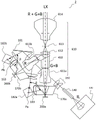
图1是示出实施方式1所涉及的投影显示装置的光学结构的典型图。FIG. 1 is a typical diagram showing an optical configuration of a projection display device according to Embodiment 1. As shown in FIG.
图2是将实施方式1中的照明光学系统的一部分提取出来显示的图。FIG. 2 is an extracted and displayed view of a part of the illumination optical system in Embodiment 1. FIG.
图3是示出实施方式1中的投影光学系统的图。FIG. 3 is a diagram showing a projection optical system in Embodiment 1. FIG.
图4的(a)是示出合成棱镜400的结构的图;图4的(b)是示出介质多层 膜405的特性的图。4(a) is a diagram showing the structure of the
图5是示出二向色镜180的特性的曲线图。FIG. 5 is a graph showing the characteristics of the
图6是示出实施方式1中从背面侧观察反射式光调制器件200b时的各光学器 件的配置的图。Fig. 6 is a diagram showing the arrangement of the respective optical devices when the reflective
图7的(a)是典型地示出从光通道140至反射式光调制器件200a的照明光 学系统的图;图7的(b)是典型地示出从光通道140至反射式光调制器件200b 的照明光学系统的图。(a) of FIG. 7 is a diagram typically showing the illumination optical system from the
图8的(a)是示出实施方式1中使用的光源装置110的结构的图;图8的(b) 是示出实施方式2中使用的光源装置110的结构的图。8( a ) is a diagram showing the configuration of the
图9的(a)是示出青色滤光片CF的透射特性的曲线图;图9的(b)是示出 红色滤光片RF的透射特性的曲线图。Fig. 9(a) is a graph showing the transmission characteristics of the cyan filter CF; Fig. 9(b) is a graph showing the transmission characteristics of the red filter RF.
图10是示出实施方式2所涉及的投影显示装置的光学结构的典型图。FIG. 10 is a typical diagram showing an optical configuration of a projection display device according to Embodiment 2. FIG.
图11是将实施方式2中的照明光学系统的一部分提取出来显示的图。FIG. 11 is an extracted and displayed view of a part of the illumination optical system in Embodiment 2. FIG.
图12是示出实施方式2中的投影光学系统的图。FIG. 12 is a diagram showing a projection optical system in Embodiment 2. FIG.
图13的(a)是示出合成棱镜410的结构的图;图13的(b)是示出介质多 层膜415的特性的图。(a) of FIG. 13 is a diagram showing the structure of the
图14是示出实施方式2中从背面侧观察反射式光调制器件200b时的各光学 器件的配置的图。Fig. 14 is a diagram showing the arrangement of each optical device when viewing the reflective
图15是用于对反射式光调制器件的结构进行说明的图。FIG. 15 is a diagram for explaining the structure of a reflective light modulation device.
图16是旋转体的俯视图。Fig. 16 is a plan view of the rotating body.
图17是示出荧光体(荧光材料)的发光特性的图。FIG. 17 is a graph showing the emission characteristics of phosphors (fluorescent materials).
图18的(a)是示出从实施方式1所涉及的光源装置110输出的照明光IL的 色光的时序图;图18的(b)是示出实施方式1所涉及的第一照明光的色光的时 序图;图18的(c)是示出从实施方式1所涉及的反射式光调制器件200a输出的 图像光的时序图;图18的(d)是示出实施方式1所涉及的第二照明光的色光的 时序图;图18的(e)是示出从实施方式1所涉及的反射式光调制器件200b输出 的图像光的时序图。(a) of FIG. 18 is a timing chart showing the color lights of the illumination light IL output from the
图19的(a)是示出从实施方式2所涉及的光源装置110输出的照明光IL的 色光的时序图;图19的(b)是示出实施方式2所涉及的第一照明光的色光的时 序图;图19的(c)是示出从实施方式2所涉及的反射式光调制器件200a输出的 图像光的时序图;图19的(d)是示出实施方式2所涉及的第二照明光的色光的 时序图;图19的(e)是示出从实施方式2所涉及的反射式光调制器件200b输出 的图像光的时序图。(a) of FIG. 19 is a timing chart showing the color lights of the illumination light IL output from the
图20的(a)是示出从实施方式2所涉及的光源装置110输出的照明光IL的 色光的时序图;图20的(b)是示出实施方式2所涉及的第一照明光的色光的时 序图;图20的(c)是示出从实施方式2所涉及的反射式光调制器件200a输出的 图像光的时序图;图20的(d)是示出实施方式2所涉及的第二照明光的色光的 时序图;图20的(e)是示出从实施方式2所涉及的反射式光调制器件200b输出 的图像光的时序图。(a) of FIG. 20 is a timing chart showing the color lights of the illumination light IL output from the
附图标记说明Explanation of reference signs
1……投影显示装置1...Projection display device
110……光源装置110...Light source device
105……二向色镜105……Dichroic mirror
107……1/4波长板107...1/4 wavelength plate
109……聚光透镜109...Concentrating lens
111R……发出红色光的固体光源111R... Solid light source emitting red light
112B……发出蓝色光的固体光源112B... solid light source emitting blue light
113G……发出绿色光的固体光源113G... solid light source emitting green light
121……电机121...Motor
122……旋转体122...rotating body
123……荧光体123... Phosphor
123Y……黄色荧光体123Y...Yellow Phosphor
124……反射部124...Reflection Department
140……光通道140... Optical channel
150……光通道侧聚光透镜150...Concentrating lens on the light channel side
151……中间像侧聚光透镜151...Concentrating lens on the intermediate image side
155……放大中间像155...Enlarge the intermediate image
160……中间像侧聚光透镜160……Intermediate image side condenser lens
161……中间像侧聚光透镜161...Concentrating lens on the intermediate image side
162……中继透镜162...Relay lens
163……调制器件侧聚光透镜163...Condenser lens on modulation device side
170a、170b……TIR棱镜170a, 170b... TIR prism
180……二向色镜180...Dichroic mirror
181……光路变更反射镜181... Optical path change reflector
182a、182b……折回反射镜182a, 182b... Folding mirrors
200a、200b……反射式光调制器件200a, 200b...reflective optical modulation device
210……激发光源组件210...Excitation light source components
400……合成棱镜400...Synthetic Prisms
401、402、403……棱镜401, 402, 403... Prisms
405……介质多层膜405...Dielectric multilayer film
410……合成棱镜410...Synthetic Prism
411、412……棱镜411, 412... Prisms
415……介质多层膜415...Dielectric multilayer film
601a……第一后组透镜601a...the first rear lens group
601b……第二后组透镜601b...The second rear group lens
602……前组透镜602...Front lens
610……投影光学系统610...Projection optical system
611a……第一中继透镜611a...the first relay lens
611b……第二中继透镜611b...second relay lens
60……投影光学系统60...Projection optical system
612……第三中继透镜612...The third relay lens
613……中间像613...Intermediate image
614……投影镜头614...Projection lens
700……投影面700...projection surface
AG1、AG2、AG3……气隙AG1, AG2, AG3...Air gap
Ex……激发光Ex...excitation light
IL……照明光IL...illumination light
LX……前组透镜的光轴LX... the optical axis of the front group lens
具体实施方式Detailed ways
下面参考附图,对实施方式所涉及的投影显示装置进行说明。Next, the projection display device according to the embodiment will be described with reference to the drawings.
[实施方式1][Embodiment 1]
图1是示出实施方式1所涉及的投影显示装置的光学结构的典型图。投影显 示装置1具备反射式光调制器件200a(第一反射式光调制器件)和反射式光调制 器件200b(第二反射式光调制器件)。在本实施方式中,作为反射式光调制器件 200a和反射式光调制器件200b,使用以阵列状设置有微镜器件的DMD。其中, 如参考图15所说明的那样,作为DMD,使用在俯视画面时,各像素的微镜的反 射面相对于画面边框倾斜45°,根据图像信号驱动反射面来变更照明光的反射方向 的器件。与各像素对应的微镜根据图像信号的亮度级被驱动,以使得反射方向通 过脉冲宽度调制而变更。FIG. 1 is a typical diagram showing an optical configuration of a projection display device according to Embodiment 1. As shown in FIG. The projection display device 1 includes a reflective
投影显示装置1具备光源装置110。光源装置110是用于对反射式光调制器件 200a和反射式光调制器件200b进行照明的光源。图8的(a)示出本实施方式中 使用的光源装置110的结构。光源装置110具备激发光源组件210,激发光源组件 210是二维地排列有多个发光器件(例如发出蓝色光的半导体激光器)且与各发光 器件对应地设置有准直透镜的组件。另外,光源装置110具备能够通过电机121 进行旋转的旋转体122,在旋转体122的主面上设置有荧光体(荧光材料)123。 进而,在激发光源组件210和荧光体123之间配置有二向色镜105、1/4波长板107 和聚光透镜。The projection display device 1 includes a
在本实施方式的光源装置中,旋转体122能够通过电机121进行旋转,在旋 转体122的主面上设置有荧光体123。图16示出旋转体122的俯视图,在旋转体 122的主面上,在以旋转轴RA为中心的环形区域的一部分上涂布有黄色荧光体 123Y,在环形区域的其余部分上未涂布荧光体,而是设置有用于反射激发光Ex 的反射部124。反射部124优选预先进行镜面加工,以高效率地反射蓝色激光。在 设置有黄色荧光体123Y的区域的基底上,设置有用于将向旋转体122的方向放射 的荧光反射到透镜侧的反射面,以提高荧光的射出效率。In the light source device of this embodiment, the
图17示出当向黄色荧光体123Y照射激发光Ex时从黄色荧光体123Y得到的 光谱的示例。图中用单点划线示出的曲线图32是黄色荧光体123Y的发光光谱。 为参考起见,用虚线曲线图31示出了一般的绿色荧光体的发光光谱,用实线曲线 图33示出了一般的红色荧光体的发光光谱。另外,在波长450nm附近观察到的峰 值并非荧光体发出的光,而是激发光Ex的一部分未被荧光体吸收而被反射后的光。 另外,图17所示的曲线图32是一个示例,在本实施方式中可以使用的荧光体的 发光特性并非必须与之严格一致。Fig. 17 shows an example of a spectrum obtained from the
通过使这样的旋转体122旋转,激发光Ex会照射黄色荧光体123Y或反射部 124中的任意一个。为了防止荧光体过热,旋转体122的基材优选使用热传导率高 的金属,为了提高空气冷却效率,有时也在基材上设置凹凸部或空孔。By rotating such a
接着,参考图8的(a)对光源装置110的各部的作用进行说明。Next, the function of each part of the
从激发光源组件210射出的准直化后的S偏光的蓝色光(激发光Ex)入射至 二向色镜105。S偏光的蓝色光(激发光Ex)被二向色镜105向旋转体122的方向 反射。经由1/4波长板107的激发光被聚光透镜聚光到旋转体122上。The collimated S-polarized blue light (excitation light Ex) emitted from the excitation
在激发光Ex被聚光的位置处存在黄色荧光体123Y的旋转时段中,发出黄色 荧光。另外,在激发光Ex被聚光的位置处存在反射部124的旋转时段中,激发光 Ex(蓝色光)被反射。In the rotation period in which the
在入射至二向色镜105的黄色荧光之中,P偏光成分几乎全部透射,而S偏光 成分则是波长在约490nm以上的大部分透射。此外,转换为P偏光的蓝色光几乎 全部透射。即,这些光高效率地从二向色镜105透射,作为光源装置的输出光被 射出,通过聚光透镜109被适当地聚光。Of the yellow fluorescent light incident on the
聚光透镜109为了适合投影光学系统610的F值而被设定为既定的NA,其将 照明光IL聚光到光通道140的入射口。如图1所示,光源装置的输出光被用作投 影显示装置的照明光IL。另外,根据情况,为了从照明光IL中排除不需要的光谱 成分,也可以在聚光透镜109与光通道140之间例如设置切换式的彩色滤光片(色 轮)。The condensing
接着,对将由光源装置110提供的照明光IL分配给反射式光调制器件200a(第 一反射式光调制器件)和反射式光调制器件200b(第二反射式光调制器件)的照 明光学系统进行说明。Next, the illumination optical system that distributes the illumination light IL supplied from the
图2是将实施方式1的照明光学系统的一部分提取出来显示的图。经由光通 道140传播的照明光IL被光通道侧聚光透镜150整形为适于对反射式光调制器件 200a和反射式光调制器件200b进行照明的光束。光通道侧聚光透镜150由单个或 多个透镜构成。FIG. 2 is an extracted and displayed view of a part of the illumination optical system according to Embodiment 1. FIG. The illumination light IL propagating through the
经由光通道侧聚光透镜150的照明光IL进一步经过中间像侧聚光透镜151而 形成放大中间像155。但是,在放大中间像155的成像位置附近配置有二向色镜 180,照明光IL的入射角η1被设定为27.5度。照明光IL中包含的红色光R从二 向色镜180透射,绿色光G和蓝色光B被二向色镜180反射。另外,照明光IL的 入射角η1并非必须是27.5度,优选满足以下条件:The illumination light IL passing through the light passage
25度<η1<32度……(条件1)25 degrees <η1<32 degrees... (Condition 1)
图5示出二向色镜180的透射率的波长依赖性。与十字分色棱镜相比,板状 二向色镜180具有PS分离宽度和角度偏移(入射角依赖性)小的优点。如图5所 示,即便入射角相对于28度变化了±10度,角度偏移虽然存在,但是偏移量小。 另外,曲线的上升沿也陡峭,几乎呈阶梯状,可见红色光的分离能力优异。FIG. 5 shows the wavelength dependence of the transmittance of the
从二向色镜180透射的红色光R用于对反射式光调制器件200b进行照明,被 二向色镜180反射的绿色光G和蓝色光B用于对反射式光调制器件200a进行照明。 换言之,照明光的放大中间像155的第一色光成分被转印到第一反射式光调制器 件,第二色光成分被转印到第二反射式光调制器件。在以下说明中,有时将用于 对反射式光调制器件200a进行照明的绿色光G和蓝色光B称为第一照明光 (G+B),将用于对反射式光调制器件200b进行照明的红色光R称为第二照明光 (R)。另外,将从二向色镜180至反射式光调制器件200a的第一照明光的光路 称为第一照明光学系统,将从二向色镜180至反射式光调制器件200b的第二照明 光的光路称为第二照明光学系统。The red light R transmitted from the
如从图1和图2中可理解的那样,在第一照明光学系统中,被二向色镜180 反射的第一照明光(G+B)经由中间像侧聚光透镜160(第一透镜)、折回反射镜182a(第一反射镜)、调制器件侧聚光透镜163、TIR棱镜170a而被聚光到反射 式光调制器件200a上。在第一照明光学系统中,由于在从光源装置110到反射式 光调制器件200a之间,在二向色镜180、折回反射镜182a、TIR棱镜170a这三个 地方被反射,因此第一照明光的折回次数为3次。As can be understood from FIGS. 1 and 2, in the first illumination optical system, the first illumination light (G+B) reflected by the
另外,从光通道140至二向色镜180的照明光IL的光轴位于与Y轴平行的方 向,即与XY平面平行的第一平面内,第一照明光的光轴在被二向色镜180反射后 直至到达折回反射镜182a为止位于与XY平面平行的第一平面内。另一方面,被 折回反射镜182a反射后,第一照明光的光轴从XY平面内偏出而具有Z方向成分。 即,第一照明光的光轴在反射式光调制器件200a的前面通过折回反射镜182a而向 与第一平面交叉的方向偏折。In addition, the optical axis of the illumination light IL from the
TIR棱镜170a是例如通过组合两个棱镜而构成的内部全反射棱镜,其使第一 照明光发生内部全反射而以既定的角度入射至反射式光调制器件200a。The
另外,照明光IL向二向色镜180入射的入射角η1如前所述例如设定为27.5 度,折回反射镜182a中的入射与反射的角度差(入射角与反射角之和)β例如设 定为59.3度。In addition, the incident angle η1 of the illumination light IL to the
另一方面,从二向色镜180透射的第二照明光(R)经由中间像侧聚光透镜161、 光路变更反射镜181、中继透镜162(第二透镜)、折回反射镜182b(第二反射镜)、 调制器件侧聚光透镜163、TIR棱镜170b而被聚光到反射式光调制器件200b上。 在第二照明光学系统中,由于在从光源装置110到反射式光调制器件200b之间, 在光路变更反射镜181、折回反射镜182b、TIR棱镜170b这三个地方被反射,因 此第二照明光的折回次数为3次。即,由于第一照明光的折回次数与第二照明光 的折回次数相等,因此能够向各反射式光调制器件照射同质的照明光,能够抑制 深浅不均的产生。On the other hand, the second illumination light (R) transmitted from the
第二照明光的光轴在从二向色镜180透射后被光路变更反射镜181反射直至 到达折回反射镜182b为止,位于与XY平面平行的第一平面内,但在被折回反射 镜182b反射后,光轴从XY平面内偏出而具有Z方向成分。即,第二照明光的光 轴在反射式光调制器件200b的前面通过折回反射镜182b而向与第一平面交叉的 方向偏折。After being transmitted from the
TIR棱镜170b是例如通过粘贴两个棱镜而构成的内部全反射棱镜,其使第二 照明光发生内部全反射而以既定的角度入射至反射式光调制器件200b。The
另外,第二照明光向光路变更反射镜181入射的入射角η2(图2)例如设定 为64度,折回反射镜182b中的入射与反射的角度差(入射角与反射角之和)β 与第一照明光同样,例如设定为59.3度。另外,关于照明光IL向二向色镜180入 射的入射角η1和第二照明光向光路变更反射镜181入射的入射角η2,设定为使以 下关系成立。In addition, the incident angle η2 (FIG. 2) at which the second illumination light is incident on the optical
η2≥η1……(条件2)η2≥η1...(Condition 2)
在第一照明光的照明光学系统与第二照明光的照明光学系统中,折回反射镜182a与折回反射镜182b、调制器件侧聚光透镜163、TIR棱镜170a与TIR棱镜170b 可以分别使用相同规格的器件。在这两个照明光学系统中,这些光学器件以相对 于反射式光调制器件的相对位置关系等同的方式配置。In the illumination optical system of the first illumination light and the illumination optical system of the second illumination light, the
图7的(a)典型地示出从光通道140至反射式光调制器件200a的照明光学系 统,图7的(b)典型地示出从光通道140至反射式光调制器件200b的照明光学 系统。此外,为了便于图示,在图7的(a)中,由二向色镜180、折回反射镜182a、 TIR棱镜170a带来的光路方向的变更省略图示,以直线方式示出光轴。同样,在 图7的(b)中,由光路变更反射镜181、折回反射镜182b、TIR棱镜170b带来的 光路方向的变更省略图示,以直线方式示出光轴。(a) of FIG. 7 typically shows the illumination optical system from the
另外,图6典型地示出从背面侧观察反射式光调制器件200b时各光学器件的 配置。此外,在图6中,照明光学系统的一部分省略图示。从折回反射镜182b的 反射点P朝向TIR棱镜170b的照明光以入射角45°入射至反射式光调制器件200b。 另外,作为反射式光调制器件200b(以及反射式光调制器件200a)来使用的DMD 器件,如已参考图15所描述的那样,使用在俯视画面时,各像素的微镜的反射面 相对于画面边框倾斜45°,根据图像信号驱动反射面来变更照明光的反射方向的器 件。In addition, Fig. 6 typically shows the arrangement of each optical device when the reflective
如图7的(a)所示,将第一照明光的光轴与二向色镜180的交点设为S,将 第一照明光的光轴与折回反射镜182a的交点设为Pa,将S与Pa的距离设为La。 另外,如图7的(b)所示,将第二照明光的光轴与二向色镜180的交点设为S, 将第二照明光的光轴与折回反射镜182b的交点设为Pb,将S与Pb的距离设为Lb。As shown in (a) of FIG. The distance between S and Pa is La. In addition, as shown in (b) of FIG. , let the distance between S and Pb be Lb.
如图7的(a)和图7的(b)所示例的那样,在本实施方式中,用于第一照 明光的折回反射镜182a和用于第二照明光的折回反射镜182b以La与Lb未必相 等,即La/Lb未必为1的方式配置。As illustrated in (a) and (b) of FIG. 7 , in the present embodiment, the
对于第一照明光和第二照明光这两者,由于从折回反射镜182a(折回反射镜182b)至反射式光调制器件200a(反射式光调制器件200b)的光路长度被设定为 相等,因此从光通道140至反射式光调制器件200a的第一照明光的光路长度与从 光通道140至反射式光调制器件200b的第二照明光的光路长度产生La-Lb=ΔL 的差异。另外,作为La/Lb不为1的结构,除了图7的(a)和图7的(b)所示的 La>Lb的结构之外,还可以以La<Lb的方式来配置用于第一照明光的折回反射 镜182a与用于第二照明光的折回反射镜182b。For both the first illumination light and the second illumination light, since the optical path lengths from the
在本实施方式中,为了尽量使第一照明光对反射式光调制器件200a进行照明 的条件与第二照明光对反射式光调制器件200b进行照明的条件一致,在第一照明 光的光路中的二向色镜180与折回反射镜182a之间配置中间像侧聚光透镜160, 在第二照明光的光路中的二向色镜180与光路变更反射镜181之间配置中间像侧 聚光透镜161,在光路变更反射镜181与折回反射镜182b之间配置中继透镜162。 通过适当地设定这些透镜的位置和焦距,能够降低光路长度差ΔL的影响而使这两 个反射式光调制器件的照明条件一致。In this embodiment, in order to make the conditions for illuminating the reflective
另外,在本实施方式中,如前所述,从具备黄色荧光体的光源装置110输出 图17所示的光谱特性的荧光,利用二向色镜180分离色光,为了提高照明光的色 纯度,优选在第一照明光学系统中设置青色滤光片CF,在第二照明光学系统中设 置红色滤光片RF。尽管设置滤光片的位置是任意的,但是在本实施方式中,考虑 光学系统的对称性,在各个光学系统的调制器件侧聚光透镜163的出射面上设置 了二向色滤光片(多层膜滤光片)。即,如图7的(a)所示,在第一照明光学系 统的调制器件侧聚光透镜163的出射面上设置具备图9的(a)所示特性的青色滤 光片CF,如图7的(b)所示,在第二照明光学系统的调制器件侧聚光透镜163 的出射面上设置具备图9的(b)所示特性的红色滤光片RF。In addition, in this embodiment, as described above, the fluorescent light having the spectral characteristics shown in FIG. Preferably, a cyan filter CF is provided in the first illumination optical system, and a red filter RF is provided in the second illumination optical system. Although the positions where the filters are set are arbitrary, in this embodiment, considering the symmetry of the optical systems, dichroic filters ( multilayer film filter). That is, as shown in (a) of Figure 7, the cyan color filter CF having the characteristic shown in (a) of Figure 9 is set on the exit surface of the modulation device
由此,反射式光调制器件200a和反射式光调制器件200b分别由第一照明光 和第二照明光进行照明。Thus, the reflective
此外,在将从二向色镜180至反射式光调制器件200a的光路长度设为LDA, 并将从二向色镜180至反射式光调制器件200b的光路长度设为LDB时,优选满 足以下条件:In addition, when the optical path length from the
0.9<LDA/LDB<1.1……(条件3)0.9<LDA/LDB<1.1...(Condition 3)
反射式光调制器件200a和反射式光调制器件200b具有以阵列状设置的多个 微镜,二者与从光源装置110照射的照明光IL的颜色切换时序同步地对照明光进 行调制。The reflective
图18的(a)~图18的(e)是为了说明光源装置110和各反射式光调制器件 的驱动时序,以时间t表示横轴的时序图。如参考图8的(a)、图16、图17说 明的那样,光源装置110使旋转体122旋转,交替输出黄色荧光体123Y发出的黄 色荧光与反射部124反射的蓝色光。如果进行控制以使旋转体122与图像信号的 一帧期间同步地旋转一圈,则如图18的(a)所示,从光源装置110交替输出Y 光与B光。18(a) to 18(e) are timing charts with time t on the horizontal axis for explaining the driving timing of the
由于二向色镜180具有图5所示的透射特性,因此被二向色镜180反射的第 一照明光如图18的(b)所示成为G光与B光交替照射的方式,从二向色镜180 透射的第二照明光如图18的(d)所示成为R光间歇照射的方式。Since the
通过与第一照明光的颜色切换时序同步地输入图像信号的G成分和B成分, 从而从反射式光调制器件200a输出图18的(c)所示的图像光G+B。另外,通过 与第二照明光的R光点亮的时序同步地输入图像信号的R成分,从而从反射式光 调制器件200b输出图18的(e)所示的图像光R。各种颜色的图像光根据图像信 号中的各种颜色成分的亮度,被反射式光调制器件进行脉冲宽度调制。在需要针 对每种颜色使相当于一个等级的脉冲宽度(时间长度)不同的情况下,可以配合 图像光的颜色来对驱动反射式光调制器件的时钟频率进行调整。When the G component and the B component of the image signal are input in synchronization with the color switching timing of the first illumination light, the image light G+B shown in (c) of FIG. 18 is output from the reflective
接着,对将从反射式光调制器件200a和反射式光调制器件200b输出的图像 光合成并投影的投影光学系统进行说明。Next, a projection optical system for combining and projecting images output from the reflective
图3是为了对投影光学系统进行说明而从图1所示的投影显示装置1的整体 结构之中将投影光学系统610的部分提取出来的图。Fig. 3 is a diagram extracting a part of the projection
如前所述,反射式光调制器件200a根据图像信号中的G色或B色的信号成分 驱动微镜器件,使第一照明光以既定的角度反射,输出图18的(c)所示的图像 光G+B。图像光G+B从TIR棱镜170a透射而入射至第一后组透镜601a,进而从 合成棱镜400透射而入射至前组透镜602,并被放大投影到投影面700(例如投影 屏幕)上。As mentioned above, the reflective
另外,反射式光调制器件200b根据图像信号中的R色的信号成分驱动微镜器 件,使第二照明光以既定的角度反射,输出图18的(e)所示的图像光R。图像光 R从TIR棱镜170b透射而入射至第二后组透镜601b,进而在合成棱镜400中发生 内部反射使光路变更而入射至前组透镜602,并被放大投影到投影面700(例如投 影屏幕)上。此外,在图1~图3中,前组透镜602的光轴LX以单点划线表示。In addition, the reflective
前组透镜602与第一后组透镜601a合在一起作为针对图像光G+B的投影镜头 发挥作用。同样地,前组透镜602与第二后组透镜601b合在一起作为针对图像光 R的投影镜头发挥作用。这里,TIR棱镜170a与TIR棱镜170b使用相同结构的器 件,第一后组透镜601a与第二后组透镜601b使用相同结构的透镜。另外,如后 所述,在合成棱镜400内,图像光R的光路长度与图像光G+B的光路长度被配置 为相等。因此,在由本实施方式构成的投影镜头系统中,投影面700上的图像的 调整(例如焦点调整)只需操作前组透镜602就能简单地进行。The combination of the
合成棱镜400使图像光R的光路变更而与图像光G+B的光路重叠,并将图像 光R及图像光G+B朝向前组透镜602引导。The
如图4的(a)所示,合成棱镜400由棱镜401、棱镜402、棱镜403这三个 棱镜构成。棱镜401与棱镜402隔着作为微小间隙的气隙AG1相对置,棱镜402 与棱镜403隔着作为微小间隙的气隙AG2相对置。在棱镜402的光学面之中,在 隔着气隙AG1与棱镜401相对置的面上设置有介质多层膜405。As shown in (a) of FIG. 4 , the
图像光R在入射至棱镜402后,在气隙AG2侧的光学面上朝向介质多层膜405 发生内部全反射。在本实施方式中,图像光R相对于介质多层膜405的入射角ω 被配置为ω=12度。介质多层膜405是具备图4的(b)所示的透射/反射特性的 膜,图像光R几乎全部被反射。此外,介质多层膜405并非在棱镜401与棱镜402 之间无间隙地被夹在中间(粘接),而是与棱镜401之间隔着气隙,因此与粘接 式的十字棱镜相比,PS分离宽度和角度偏移的偏移量小,曲线图中曲线的上升沿 陡峭,几乎呈阶梯状。被介质多层膜405反射的图像光R从气隙AG2、棱镜403 透射而入射至前组透镜602。After the image light R enters the
另一方面,图像光G+B从棱镜401、气隙AG1透射,以入射角12度入射至 介质多层膜405上。从前面说明的图4的(b)的透射/反射特性显然可知,图像光 G+B从介质多层膜405透射。图像光G+B进一步从棱镜402、气隙AG2和棱镜 403透射而入射至前组透镜602。On the other hand, the image light G+B is transmitted through the
此外,相对于介质多层膜405的入射角被配置为,除去制造上的误差,在图 像光R与图像光G+B中实质上相等。另外,棱镜402和棱镜401的形状被设定为, 使得图像光R入射至棱镜402内之后直至到达介质多层膜405为止的光路长度与 图像光G+B入射至棱镜401内之后直至出射为止的光路长度相等。In addition, the incident angles with respect to the
根据以上说明的本实施方式,例如与专利文献1中公开的双板式显示装置相 比,能够减小投影镜头的后焦距,因此能够使装置小型化。而且,由于使用相对 于画面的垂直方向(V方向)以45度的方向配置微镜这种类型的反射式光调制器 件,因此在成本上有利。另外,与专利文献2所公开的双板式显示装置相比,由 于是不使用偏光特性依赖于入射角而大幅变化的十字分色棱镜的光学系统,因此 能够显示颜色深浅均匀的高画质的图像。即,根据本实施方式,能够实现在高画 质、小型化、低成本间达到良好平衡的、通用性高的双板式的投影显示装置。According to the present embodiment described above, for example, compared with the two-panel display device disclosed in Patent Document 1, the back focus of the projection lens can be reduced, so that the device can be miniaturized. Furthermore, since a reflective light modulation device in which micromirrors are arranged in a direction of 45 degrees with respect to the vertical direction (V direction) of the screen is used, it is advantageous in terms of cost. In addition, compared to the two-panel display device disclosed in Patent Document 2, since it is an optical system that does not use a cross dichroic prism whose polarization characteristics vary greatly depending on the incident angle, it is possible to display high-quality images with uniform color shades. . That is, according to the present embodiment, it is possible to realize a highly versatile two-panel type projection display device that achieves a good balance between high image quality, miniaturization, and low cost.
[实施方式2][Embodiment 2]
接着,对实施方式2所涉及的投影显示装置进行说明。其中,对于与实施方 式1相同或类似的部分,简化或省略说明。Next, a projection display device according to Embodiment 2 will be described. However, descriptions of the same or similar parts as those in Embodiment 1 are simplified or omitted.
图10是示出实施方式2所涉及的投影显示装置的光学结构的典型图。投影显 示装置2具备反射式光调制器件200a(第一反射式光调制器件)和反射式光调制 器件200b(第二反射式光调制器件)。在本实施方式中,也与实施方式1同样, 作为反射式光调制器件200a和反射式光调制器件200b,使用以阵列状设置有微镜 器件的DMD。另外,如参考图15所说明的那样,作为DMD,使用在俯视画面时, 各像素的微镜的反射面相对于画面边框倾斜45°,根据图像信号驱动反射面来变更 照明光的反射方向的器件。与各像素对应的微镜根据图像信号的亮度级被驱动, 以使得反射方向通过脉冲宽度调制而变更。FIG. 10 is a typical diagram showing an optical configuration of a projection display device according to Embodiment 2. FIG. The projection display device 2 includes a reflective
投影显示装置2具备光源装置110。光源装置110是用于对反射式光调制器件 200a和反射式光调制器件200b进行照明的光源。The projection display device 2 includes a
图8的(b)示出本实施方式中使用的光源装置110的结构。本实施方式的光 源装置110不像实施方式1的光源装置那样激发荧光体以使其发光,而是将能够 独立驱动的、色光不同的固体光源(例如,R、G、B的半导体激光器或LED)的 输出光合成以作为照明光IL输出。即,光源装置110具备发出红色光的固体光源 111R、发出蓝色光的固体光源112B、发出绿色光的固体光源113G、以及对各发 光源的光进行聚光的透镜115,其使用反射蓝色光的二向色镜807和反射红色光的 二向色镜808来使各色光的光路重叠,经由聚光透镜109向光通道140射出照明 光IL。通过使用固体光源(例如,半导体激光器或LED),在本实施方式中,与荧光体相比,能够向光通道140射出色纯度高的照明光IL。(b) of FIG. 8 shows the structure of the
图11是将实施方式2的照明光学系统的一部分提取出来显示的图,与实施方 式1中的图2相对应。本实施方式中的照明光学系统的基本结构与实施方式1类 似,但如图中的表所示,各光学器件的设置角度和位置不同。在本实施方式中, 为了尽量使第一照明光对反射式光调制器件200a进行照明的条件与第二照明光对 反射式光调制器件200b进行照明的条件一致,也是在第一照明光的光路中的二向 色镜180与折回反射镜182a之间配置中间像侧聚光透镜160,在第二照明光的光 路中的二向色镜180与光路变更反射镜181之间配置中间像侧聚光透镜161,在光 路变更反射镜181与折回反射镜182b之间配置中继透镜162。通过适当地设定这 些透镜的位置和焦距,能够降低光路长度差ΔL的影响而使这两个反射式光调制器 件的照明条件一致。Fig. 11 is a diagram showing a part of the illumination optical system in Embodiment 2 extracted, and corresponds to Fig. 2 in Embodiment 1. The basic structure of the illumination optical system in this embodiment is similar to Embodiment 1, but as shown in the table in the figure, the installation angle and position of each optical device are different. In this embodiment, in order to make the conditions for illuminating the reflective
另外,图14典型地示出从背面侧观察反射式光调制器件200b时各光学器件 的配置。此外,在图14中,照明光学系统的一部分省略图示。从折回反射镜182b 的反射点P朝向TIR棱镜170b的照明光以入射角45°入射至反射式光调制器件 200b。另外,作为反射式光调制器件200b(以及反射式光调制器件200a)来使用 的DMD器件,如已参考图15所描述的那样,使用在俯视画面时,各像素的微镜 的反射面相对于画面边框倾斜45°,根据图像信号驱动反射面来变更照明光的反射 方向的器件。In addition, Fig. 14 typically shows the arrangement of each optical device when the reflective
反射式光调制器件200a和反射式光调制器件200b具有以阵列状设置的多个 微镜,二者与从光源装置110照射的照明光IL的颜色切换时序同步地对照明光进 行调制。The reflective
图19的(a)~图19的(e)是为了说明光源装置110和各反射式光调制器件 的驱动时序,以时间t表示横轴的时序图。如参考图8的(b)所说明的那样,光 源装置110具备发出红色光的固体光源111R、发出蓝色光的固体光源112B、发出 绿色光的固体光源113G,以作为能够独立驱动的、色光不同的固体光源。如图19 的(a)所示,在相当于图像信号的一帧的期间之中,例如约2/3使固体光源111R 和发出绿色光的固体光源113G同时点亮以输出R光和G光,其余约1/3使固体光 源112B点亮以输出B光。19(a) to 19(e) are timing charts with time t on the horizontal axis for explaining the driving timing of the
由于二向色镜180具有图5所示的透射特性,因此被二向色镜180反射的第 一照明光如图19的(b)所示成为G光与B光交替照射的方式,从二向色镜180 透射的第二照明光如图19的(d)所示成为R光间歇照射的方式。Since the
通过与第一照明光的颜色切换时序同步地输入图像信号的G成分和B成分, 从而从反射式光调制器件200a输出图19的(c)所示的图像光G+B。另外,通过 与第二照明光的R光点亮的时序同步地输入图像信号的R成分,从而从反射式光 调制器件200b输出图19的(e)所示的图像光R。各种颜色的图像光根据图像信 号中的各种颜色成分的亮度,被反射式光调制器件进行脉冲宽度调制。在需要针 对每种颜色使相当于一个等级的脉冲宽度(时间长度)不同的情况下,可以配合 图像光的颜色来对驱动反射式光调制器件的时钟频率进行调整。When the G component and the B component of the image signal are input in synchronization with the color switching timing of the first illumination light, the image light G+B shown in (c) of FIG. 19 is output from the reflective
此外,驱动时序不限于图19的(a)~图19的(e)的示例,例如也可以是图 20的(a)~图20的(e)所示的方式。如图20的(a)所示,在相当于图像信号 的一帧的期间的整个范围中使固体光源111R点亮以输出R光,与此同时,在相当 于图像信号的一帧的期间之中,例如约2/3使发出绿色光的固体光源113G点亮以 输出G光,其余约1/3使固体光源112B点亮以输出B光。In addition, the driving timing is not limited to the examples shown in (a) to (e) of FIG. 19 , and may be, for example, those shown in (a) to (e) of FIG. 20 . As shown in (a) of FIG. 20 , the solid-
由于二向色镜180具有图5所示的透射特性,因此被二向色镜180反射的第 一照明光如图20的(b)所示成为G光与B光交替照射的方式,从二向色镜180 透射的第二照明光如图20的(d)所示成为R光连续照射的方式。Since the
通过与第一照明光的颜色切换时序同步地输入图像信号的G成分和B成分, 从而从反射式光调制器件200a输出图20的(c)所示的图像光G+B。另外,通过 与帧的切换时序同步地输入图像信号的R成分,从而从反射式光调制器件200b输 出图20的(e)所示的图像光R。各种颜色的图像光根据图像信号中的各种颜色成 分的亮度,被反射式光调制器件进行脉冲宽度调制。在需要针对每种颜色使相当 于一个等级的脉冲宽度(时间长度)不同的情况下,可以配合图像光的颜色来对 驱动反射式光调制器件的时钟频率进行调整。When the G component and the B component of the image signal are input in synchronization with the color switching timing of the first illumination light, the image light G+B shown in (c) of FIG. 20 is output from the reflective
接着,对将从反射式光调制器件200a和反射式光调制器件200b输出的图像 光合成并投影的投影光学系统进行说明。Next, a projection optical system for combining and projecting images output from the reflective
图12是为了对投影光学系统进行说明而从图10所示的投影显示装置2的整 体结构之中将投影光学系统610的部分提取出来的图。Fig. 12 is a diagram extracting a portion of the projection
如前所述,反射式光调制器件200a根据图像信号中的G色或B色的信号成分 驱动微镜器件,使第一照明光以既定的角度反射,输出图19的(c)或图20的(c) 所示的图像光G+B。图像光G+B从TIR棱镜170a透射而入射至第一中继透镜611a, 进而从合成棱镜410透射并经由第三中继透镜612而形成中间像613。中间像613 通过配置在放大侧的投影镜头614被放大投影到投影面700(例如投影屏幕)上。As mentioned above, the reflective
另外,反射式光调制器件200b根据图像信号中的R色的信号成分驱动微镜器 件,使第二照明光以既定的角度反射,输出图19的(e)或图20的(e)所示的图 像光R。图像光R从TIR棱镜170b透射而入射至第二中继透镜611b,进而在合成 棱镜410中发生内部反射而变更光路,并经由第三中继透镜612而形成中间像613。 中间像613通过投影镜头614被放大投影到投影面700(例如投影屏幕)上。In addition, the reflective
这样,在本实施方式中,与实施方式1不同之处在于为如下结构:采用中继 透镜在投影镜头614的前面临时形成显示图像的中间像。在本实施方式中,由于 能够缩小中继透镜光阑附近的光线直径,因此能够使合成棱镜410小型化。Thus, this embodiment differs from Embodiment 1 in that it has a configuration in which an intermediate image of a display image is temporarily formed in front of the
合成棱镜410使图像光R的光路变更而与图像光G+B的光路重叠,并将图像 光R和图像光G+B朝向前组透镜602引导。The
如图13的(a)所示,合成棱镜410由棱镜411和棱镜412这两个棱镜构成。 棱镜411与棱镜412隔着作为微小间隙的气隙AG3相对置。在棱镜411的光学面 之中,在隔着气隙AG3而与棱镜412相对置的面上设置有介质多层膜415。As shown in (a) of FIG. 13 , the
图像光R入射至棱镜411后,在第三中继透镜612侧的光学面上朝向介质多 层膜415发生内部全反射。在本实施方式中,图像光R相对于介质多层膜415的 入射角ω被配置为ω=26.5度。介质多层膜415是具备图13的(b)所示的透射/ 反射特性的膜,对固体光源的单色性良好的照明光进行调制后的图像光R几乎全 部被反射。此外,介质多层膜415并非在棱镜411与棱镜412之间无间隙地被夹 在中间(粘接),而是与棱镜412之间隔着气隙,因此与粘接式的十字棱镜相比, PS分离宽度和角度偏移的偏移量小,曲线图中曲线的上升沿陡峭,几乎呈阶梯状。 被介质多层膜415反射的图像光R从棱镜411透射而入射至第三中继透镜612。After the image light R enters the
另一方面,图像光G+B从棱镜412、气隙AG3透射,以入射角26.5度入射至 介质多层膜415。从前面说明的图13的(b)的透射/反射特性显然可知,对固体 光源的单色性良好的照明光进行调制后的图像光G+B从介质多层膜415透射。图 像光G+B进一步从棱镜411透射而入射至第三中继透镜612。On the other hand, the image light G+B is transmitted through the
此外,相对于介质多层膜415的入射角被配置为在图像光R与图像光G+B中 相等。另外,棱镜411和棱镜412的形状被设定为,使得图像光R入射至棱镜411 内之后直至到达介质多层膜415为止的光路长度与图像光G+B入射至棱镜412内 之后直至射出为止的光路长度相等。In addition, the incident angles with respect to the
根据以上说明的本实施方式,例如与专利文献1中公开的双板式显示装置相 比,能够减小投影镜头的后焦距,因此能够使装置小型化。而且,由于使用相对 于画面的垂直方向(V方向)以45度的方向配置微镜这种类型的反射式光调制器 件,因此在成本上有利。另外,与专利文献2所公开的双板式显示装置相比,由 于是不使用偏光特性依赖于入射角而大幅变化的十字分色棱镜的光学系统,因此 能够显示颜色深浅均匀的高画质的图像。即,根据本实施方式,能够实现在高画 质、小型化、低成本间达到良好平衡的、通用性高的双板式的投影显示装置。According to the present embodiment described above, for example, compared with the two-panel display device disclosed in Patent Document 1, the back focus of the projection lens can be reduced, so that the device can be miniaturized. Furthermore, since a reflective light modulation device in which micromirrors are arranged in a direction of 45 degrees with respect to the vertical direction (V direction) of the screen is used, it is advantageous in terms of cost. In addition, compared to the two-panel display device disclosed in Patent Document 2, since it is an optical system that does not use a cross dichroic prism whose polarization characteristics vary greatly depending on the incident angle, it is possible to display high-quality images with uniform color shades. . That is, according to the present embodiment, it is possible to realize a highly versatile two-panel type projection display device that achieves a good balance between high image quality, miniaturization, and low cost.
[其他实施方式][Other implementations]
本发明的实施并不限于以上描述的实施方式或具体实施例,而是可以在本发 明的技术思想内进行多种变形。The implementation of the present invention is not limited to the embodiments or specific examples described above, but various modifications can be made within the technical idea of the present invention.
例如,可以将实施方式1中使用的光源装置与实施方式2中使用的形成图像 中间像的投影光学系统组合起来。或者,也可以将实施方式2中使用的光源装置 与实施方式1中使用的不形成图像中间像的投影光学系统组合起来。For example, the light source device used in Embodiment 1 and the projection optical system used in Embodiment 2 to form an intermediate image may be combined. Alternatively, the light source device used in Embodiment 2 may be combined with the projection optical system used in Embodiment 1 that does not form an intermediate image.
在实施方式1中,入射至合成棱镜400的介质多层膜405的第一图像光(R+G) 与第二图像光(R)的入射角ω设为除制造上的误差以外实质上相等的大小,并设 为ω=12度。另外,在实施方式2中,入射至合成棱镜410的介质多层膜415的 第一图像光(R+G)与第二图像光(R)的入射角ω设为除制造上的误差以外实质 上相等的大小,并设为ω=26.5度。在实施本发明时,入射角ω并不限于12度或26.5度,入射角ω设定在10度以上且27度以下的范围内。In Embodiment 1, the incident angles ω of the first image light (R+G) and the second image light (R) incident on the
例如,屏幕可以作为投影显示系统的构成要素而经常与投影显示装置配套使 用,但是本发明的实施方式并不限定于此。如上所述,实施方式所涉及的投影显 示装置在对显示图像进行光学调整时的操作简单,因此也适用于便携式用途,例 如能够容易地在未设置屏幕的建筑物的墙壁等任意场所的任意面上投影出显示图 像。For example, a screen is often used together with a projection display device as a component of a projection display system, but the embodiments of the present invention are not limited thereto. As described above, the projection display device according to the embodiment is easy to operate when optically adjusting the displayed image, so it is also suitable for portable use, for example, it can be easily placed on any surface of any place such as the wall of a building without a screen. The display image is projected on.
Claims (7)
Applications Claiming Priority (2)
| Application Number | Priority Date | Filing Date | Title |
|---|---|---|---|
| JP2021085314A JP2022178477A (en) | 2021-05-20 | 2021-05-20 | Projection display device |
| JP2021-085314 | 2021-05-20 |
Publications (2)
| Publication Number | Publication Date |
|---|---|
| CN115327842A true CN115327842A (en) | 2022-11-11 |
| CN115327842B CN115327842B (en) | 2025-10-24 |
Family
ID=83916516
Family Applications (1)
| Application Number | Title | Priority Date | Filing Date |
|---|---|---|---|
| CN202210522597.0A Active CN115327842B (en) | 2021-05-20 | 2022-05-13 | A projection display device |
Country Status (2)
| Country | Link |
|---|---|
| JP (1) | JP2022178477A (en) |
| CN (1) | CN115327842B (en) |
Citations (10)
| Publication number | Priority date | Publication date | Assignee | Title |
|---|---|---|---|---|
| JPH0375619A (en) * | 1989-08-18 | 1991-03-29 | Citizen Watch Co Ltd | Reflection type display device |
| WO1996036184A1 (en) * | 1995-05-11 | 1996-11-14 | Digital Projection Limited | Projection device |
| CN1269518A (en) * | 1999-03-02 | 2000-10-11 | 精工爱普生株式会社 | Projection type displaying apparatus and prism used in said apparatus |
| US20070014114A1 (en) * | 2003-09-05 | 2007-01-18 | Sim2 Multimedia S.P.A. | Illumination system for videoprojector utilizing a plurality of dmd devices |
| US20070229766A1 (en) * | 2006-03-29 | 2007-10-04 | Seiko Epson Corporation | Modulation Apparatus and Projector |
| JP2010128239A (en) * | 2008-11-28 | 2010-06-10 | Olympus Corp | Separation/synthesis optical system and multi-plate type projector using the same |
| CN103630955A (en) * | 2012-08-27 | 2014-03-12 | 柯尼卡美能达株式会社 | Projection type display apparatus |
| JP2018146951A (en) * | 2017-03-08 | 2018-09-20 | パナソニックIpマネジメント株式会社 | Projection-type image display device |
| US20190361333A1 (en) * | 2018-05-28 | 2019-11-28 | Panasonic Intellectual Property Management Co., Ltd. | Prism device for use in two-plate video projector apparatus capable of reducing internal stray light of prism device |
| CN112578617A (en) * | 2019-09-30 | 2021-03-30 | 深圳光峰科技股份有限公司 | Optical engine system and projection system |
-
2021
- 2021-05-20 JP JP2021085314A patent/JP2022178477A/en active Pending
-
2022
- 2022-05-13 CN CN202210522597.0A patent/CN115327842B/en active Active
Patent Citations (10)
| Publication number | Priority date | Publication date | Assignee | Title |
|---|---|---|---|---|
| JPH0375619A (en) * | 1989-08-18 | 1991-03-29 | Citizen Watch Co Ltd | Reflection type display device |
| WO1996036184A1 (en) * | 1995-05-11 | 1996-11-14 | Digital Projection Limited | Projection device |
| CN1269518A (en) * | 1999-03-02 | 2000-10-11 | 精工爱普生株式会社 | Projection type displaying apparatus and prism used in said apparatus |
| US20070014114A1 (en) * | 2003-09-05 | 2007-01-18 | Sim2 Multimedia S.P.A. | Illumination system for videoprojector utilizing a plurality of dmd devices |
| US20070229766A1 (en) * | 2006-03-29 | 2007-10-04 | Seiko Epson Corporation | Modulation Apparatus and Projector |
| JP2010128239A (en) * | 2008-11-28 | 2010-06-10 | Olympus Corp | Separation/synthesis optical system and multi-plate type projector using the same |
| CN103630955A (en) * | 2012-08-27 | 2014-03-12 | 柯尼卡美能达株式会社 | Projection type display apparatus |
| JP2018146951A (en) * | 2017-03-08 | 2018-09-20 | パナソニックIpマネジメント株式会社 | Projection-type image display device |
| US20190361333A1 (en) * | 2018-05-28 | 2019-11-28 | Panasonic Intellectual Property Management Co., Ltd. | Prism device for use in two-plate video projector apparatus capable of reducing internal stray light of prism device |
| CN112578617A (en) * | 2019-09-30 | 2021-03-30 | 深圳光峰科技股份有限公司 | Optical engine system and projection system |
Also Published As
| Publication number | Publication date |
|---|---|
| JP2022178477A (en) | 2022-12-02 |
| CN115327842B (en) | 2025-10-24 |
Similar Documents
| Publication | Publication Date | Title |
|---|---|---|
| US10819961B2 (en) | Light source apparatus for use in projection three-dimensional display apparatus, with dynamic diffusion plate | |
| JP5914878B2 (en) | Light source device and projection display device | |
| US9081268B2 (en) | Lighting device and projection-type display apparatus including lighting device | |
| EP3598230B1 (en) | Light source device and projection system | |
| US20070297061A1 (en) | Optical Integrator, Illuminator and Projection Type Image Display | |
| CN108227356B (en) | Projection display system | |
| JP4183663B2 (en) | Illumination device and projection display device | |
| JP2022085665A (en) | Light source device, image projection device, and light source optical system | |
| CN115704986B (en) | Wavelength conversion plate, light source device and image projection equipment | |
| US7872216B2 (en) | Projector having two image formation units for projecting a light beam | |
| CN101454718B (en) | Illumination device and projection type video display device using the same | |
| CN110637248A (en) | Spatial light modulation image display projector device with solid-state lighting source | |
| CN210835555U (en) | Light source device and projection display device | |
| JP4162484B2 (en) | Projection display device | |
| JP2014186080A (en) | Light source device and projection video display device | |
| JP6659061B2 (en) | projector | |
| JP7149457B2 (en) | Light source device and projection type image display device | |
| CN112424687A (en) | Illumination device and projector | |
| KR20170133936A (en) | Light source device and projector comprising the same | |
| CN114868080A (en) | Illumination device and display apparatus | |
| CN113296340B (en) | Projection display device | |
| CN115327842B (en) | A projection display device | |
| JP4166261B2 (en) | Illumination device and projection display device | |
| JP2007065412A (en) | Illuminating device and projection type video display device | |
| JP2023024245A (en) | Wave conversion plate, light source device, and image projector |
Legal Events
| Date | Code | Title | Description |
|---|---|---|---|
| PB01 | Publication | ||
| PB01 | Publication | ||
| SE01 | Entry into force of request for substantive examination | ||
| SE01 | Entry into force of request for substantive examination | ||
| GR01 | Patent grant | ||
| GR01 | Patent grant | ||
| CP03 | Change of name, title or address | ||
| CP03 | Change of name, title or address |
Address after: 100029 room 227, NO.201, second floor, building 3, yard a 29, Middle North Third Ring Road, Xicheng District, Beijing Patentee after: Sonoc (Beijing) Technology Co.,Ltd. Country or region after: China Address before: 100029 No. 26, Huangsi Street, Xicheng District, Beijing Patentee before: Sonoc (Beijing) Technology Co.,Ltd. Country or region before: China |