KR20170133936A - Light source device and projector comprising the same - Google Patents
Light source device and projector comprising the same Download PDFInfo
- Publication number
- KR20170133936A KR20170133936A KR1020160065401A KR20160065401A KR20170133936A KR 20170133936 A KR20170133936 A KR 20170133936A KR 1020160065401 A KR1020160065401 A KR 1020160065401A KR 20160065401 A KR20160065401 A KR 20160065401A KR 20170133936 A KR20170133936 A KR 20170133936A
- Authority
- KR
- South Korea
- Prior art keywords
- light source
- light
- excitation light
- excitation
- emitting
- Prior art date
- Legal status (The legal status is an assumption and is not a legal conclusion. Google has not performed a legal analysis and makes no representation as to the accuracy of the status listed.)
- Ceased
Links
Images


Classifications
-
- G—PHYSICS
- G03—PHOTOGRAPHY; CINEMATOGRAPHY; ANALOGOUS TECHNIQUES USING WAVES OTHER THAN OPTICAL WAVES; ELECTROGRAPHY; HOLOGRAPHY
- G03B—APPARATUS OR ARRANGEMENTS FOR TAKING PHOTOGRAPHS OR FOR PROJECTING OR VIEWING THEM; APPARATUS OR ARRANGEMENTS EMPLOYING ANALOGOUS TECHNIQUES USING WAVES OTHER THAN OPTICAL WAVES; ACCESSORIES THEREFOR
- G03B21/00—Projectors or projection-type viewers; Accessories therefor
- G03B21/14—Details
- G03B21/20—Lamp housings
- G03B21/2006—Lamp housings characterised by the light source
- G03B21/2033—LED or laser light sources
-
- G—PHYSICS
- G02—OPTICS
- G02B—OPTICAL ELEMENTS, SYSTEMS OR APPARATUS
- G02B27/00—Optical systems or apparatus not provided for by any of the groups G02B1/00 - G02B26/00, G02B30/00
- G02B27/10—Beam splitting or combining systems
- G02B27/14—Beam splitting or combining systems operating by reflection only
- G02B27/141—Beam splitting or combining systems operating by reflection only using dichroic mirrors
-
- H—ELECTRICITY
- H01—ELECTRIC ELEMENTS
- H01S—DEVICES USING THE PROCESS OF LIGHT AMPLIFICATION BY STIMULATED EMISSION OF RADIATION [LASER] TO AMPLIFY OR GENERATE LIGHT; DEVICES USING STIMULATED EMISSION OF ELECTROMAGNETIC RADIATION IN WAVE RANGES OTHER THAN OPTICAL
- H01S5/00—Semiconductor lasers
- H01S5/02—Structural details or components not essential to laser action
- H01S5/024—Arrangements for thermal management
- H01S5/02476—Heat spreaders, i.e. improving heat flow between laser chip and heat dissipating elements
-
- H—ELECTRICITY
- H01—ELECTRIC ELEMENTS
- H01S—DEVICES USING THE PROCESS OF LIGHT AMPLIFICATION BY STIMULATED EMISSION OF RADIATION [LASER] TO AMPLIFY OR GENERATE LIGHT; DEVICES USING STIMULATED EMISSION OF ELECTROMAGNETIC RADIATION IN WAVE RANGES OTHER THAN OPTICAL
- H01S5/00—Semiconductor lasers
- H01S5/40—Arrangement of two or more semiconductor lasers, not provided for in groups H01S5/02 - H01S5/30
- H01S5/4025—Array arrangements, e.g. constituted by discrete laser diodes or laser bar
- H01S5/4087—Array arrangements, e.g. constituted by discrete laser diodes or laser bar emitting more than one wavelength
- H01S5/4093—Red, green and blue [RGB] generated directly by laser action or by a combination of laser action with nonlinear frequency conversion
Landscapes
- Physics & Mathematics (AREA)
- General Physics & Mathematics (AREA)
- Optics & Photonics (AREA)
- Condensed Matter Physics & Semiconductors (AREA)
- Electromagnetism (AREA)
- Projection Apparatus (AREA)
Abstract
본 발명은, 적어도 세 개 색의 광을 조사하는 광원 장치에 있어서, 적색 광을 조사하는 제1 광원 모듈을 포함하되, 상기 제1 광원 모듈은, 여기 광의 파장을 변환하여 적색의 광을 발광하는 형광체층을 포함한 형광체 기판, 상기 형광체 기판으로 제1 여기 광(excitation light)을 조사하는 제1 여기 광원 및 상기 형광체 기판으로 제2 여기 광을 조사하는 제2 여기 광원을 포함하는 것을 특징으로 하는 광원 장치를 제공한다.The present invention provides a light source device for emitting light of at least three colors, comprising a first light source module for emitting red light, wherein the first light source module converts the wavelength of the excitation light to emit red light A phosphor substrate including a phosphor layer, a first excitation light source for emitting a first excitation light to the phosphor substrate, and a second excitation light source for emitting a second excitation light to the phosphor substrate. Device.
Description
본 발명은, 광원 장치 및 이를 포함하는 영상투사장치에 관한 것이다.The present invention relates to a light source apparatus and an image projection apparatus including the same.
정보화시대가 급속히 발전함에 따라 대화면을 구현하는 디스플레이 기기의 중요성이 강조되고 있다. 이러한 대화면을 구현하는 기기의 일 예로서 영상을 확대하여 투사하는 기능을 갖춘 프로젝터(projector)가 있다.As the information age rapidly develops, the importance of a display device that realizes a large screen is emphasized. As an example of a device for realizing such a large screen, there is a projector having a function of enlarging and projecting an image.
이러한 프로젝터는 점점 소형화, 경량화되고 있는 추세로서, 현재는 미니 프로젝터(mini projector)나 피코 프로젝터(pico projector)와 같은 초소형 프로젝터가 연구 개발되고 있다. Such a projector is becoming increasingly smaller and lighter in weight, and currently, miniature projectors such as a mini projector and a pico projector are being researched and developed.
이와 같은 추세에서, 종래 프로젝터의 광학계는 광원으로 적색 엘이디(Red LED), 녹색 엘이디(Green LED), 청색 엘이디(Blue LED)를 모두 사용하고 있다.In such a trend, the optical system of the conventional projector uses a red LED, a green LED, and a blue LED as light sources.
도 1은 종래 광원 장치를 포함한 영상투사장치의 광학계를 나타낸 도면으로서, 구체적으로 반사형 디스플레이를 사용한 영상투사장치의 광학계를 나타낸 도면이다.1 is a view showing an optical system of an image projecting apparatus including a conventional light source apparatus, specifically showing an optical system of an image projecting apparatus using a reflective display.
즉, 도 1에 도시한 바와 같이, 종래 영상투사장치(1)는 광원으로서 적색 광원 모듈(11)(일 예로, 적색 엘이디(11a)를 포함할 수 있다), 녹색 광원 모듈(13)(일 예로, 녹색 엘이디(13a)를 포함할 수 있다) 및 청색 광원(12)(일 예로, 청색 엘이디(12a)를 포함할 수 있다)을 사용하고 있다.1, the conventional
그러나 종래와 같이, 광원으로서 적색 엘이디(11a)를 포함하는 경우 다음과 같은 문제가 발생할 수 있다.However, when the
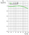
도 2a는 적색 엘이디의 열적 특성을 나타낸 그래프로서, X축은 접합 온도(junction temperature)(Tj)를 가리키고, Y축은 25℃를 기준으로 한 광량을 가리킨다.2A is a graph showing the thermal characteristics of a red LED, wherein an X axis indicates a junction temperature (Tj), and a Y axis indicates a light amount based on 25 deg.
엘이디는 접합 온도에 의해 광량이 고정되기 때문에, 도 2a에 도시한 바와 같이, 적색 엘이디의 광량을 25℃ 기준으로 80% 이상을 유지하려면 엘이디의 접합 온도를 45℃ 이하로 유지하여야 한다.As shown in FIG. 2A, since the amount of light is fixed by the junction temperature of the LED, the junction temperature of the LED must be maintained at 45 ° C or lower in order to maintain the light amount of the red LED at 80% or more based on 25 ° C.
따라서, 적색 엘이디에 대해서는 냉각이 잘 이루어져야 하기 때문에, 이러한 냉각 조건을 만족시키기 위해, 영상투사장치는 대용량의 냉각 장치가 요구되며, 그에 따라 대용량의 팬(fan)이 요구된다.Therefore, since the red LED needs to be cooled well, a large-capacity cooling apparatus is required for the image projection apparatus to satisfy such a cooling condition, and accordingly, a large-capacity fan is required.
이러한 요구에 따라 종래 영상투사장치(1)의 경우, 영상투사장치를 소형화하거나 경량화하는 데에 한계에 부딪힐 수밖에 없으며, 또한 대용량 팬의 구동에 따라 진동이나 소음의 발생은 불가피한 문제가 있다.In the case of the conventional
따라서, 이러한 문제점을 효과적으로 해결할 수 있는 기술 구현 필요성이 대두하고 있다.Therefore, there is a need for a technique for effectively solving such a problem.
본 발명은, 저용량의 냉각장치를 사용한 환경에서도 최대 광량을 확보할 수 있는 광원 장치 및 이를 포함한 영상투사장치를 제공하고자 한다.An object of the present invention is to provide a light source device capable of securing a maximum amount of light even in an environment using a low-capacity cooling device, and an image projection device including the same.
본 발명은, 적어도 세 개 색의 광을 조사하는 광원 장치에 있어서, 적색 광을 조사하는 제1 광원 모듈을 포함하되, 상기 제1 광원 모듈은, 여기 광의 파장을 변환하여 적색의 광을 발광하는 형광체층을 포함한 형광체 기판, 상기 형광체 기판으로 제1 여기 광(excitation light)을 조사하는 제1 여기 광원 및 상기 형광체 기판으로 제2 여기 광을 조사하는 제2 여기 광원을 포함하는 것을 특징으로 하는 광원 장치를 제공한다.The present invention provides a light source device for emitting light of at least three colors, comprising a first light source module for emitting red light, wherein the first light source module converts the wavelength of the excitation light to emit red light A phosphor substrate including a phosphor layer, a first excitation light source for emitting a first excitation light to the phosphor substrate, and a second excitation light source for emitting a second excitation light to the phosphor substrate. Device.
일 실시예에 따라, 상기 제1 여기 광원은, 상기 형광체 기판의 일 면에 위치하여 상기 형광체 기판으로 상기 제1 여기 광을 조사하고, 상기 제2 여기 광원은, 상기 형광체 기판의 타 면에 위치하여 상기 형광체 기판으로 제2 여기 광을 조사할 수 있다.According to one embodiment, the first excitation light source is disposed on one surface of the phosphor substrate and irradiates the first excitation light to the phosphor substrate, and the second excitation light source is disposed on the other surface of the phosphor substrate So that the second excitation light can be irradiated to the phosphor substrate.
일 실시예에 따라, 상기 제1 여기 광원은 청색 발광 다이오드이고, 상기 제2 여기 광원은 청색 레이저 다이오드일 수 있다.According to an embodiment, the first excitation light source may be a blue light emitting diode and the second excitation light source may be a blue laser diode.
일 실시예에 따라, 상기 제2 여기 광원의 광 경로 상에 배치된 적색 이색성 거울을 더 포함하되, 상기 적색 이색성 거울은, 상기 형광체층에 의해 발광된 적색의 광을 상기 광원 장치 외부로 반사시킬 수 있다.According to an embodiment, there is further provided a red dichroic mirror disposed on a light path of the second excitation light source, wherein the red dichromatic mirror reflects red light emitted by the phosphor layer to the outside of the light source device Can be reflected.
일 실시예에 따라, 상기 제1 여기 광 및 상기 제2 여기 광을 합성하여, 합성된 광을 상기 형광체 기판으로 조사하는 광 합성 모듈을 더 포함할 수 있다.The apparatus may further include a light combining module for combining the first excitation light and the second excitation light and irradiating the synthesized light to the phosphor substrate.
일 실시예에 따라, 상기 광원 장치는, 녹색 광을 조사하는 제2 광원 모듈 및 청색 광을 조사하는 제3 광원 모듈을 더 포함할 수 있다.According to an embodiment, the light source device may further include a second light source module for emitting green light and a third light source module for emitting blue light.
또한, 본 발명은 상기 광원 장치 및 상기 광원 장치로부터 입사되는 광을 이용하여 이미지를 형성하는 이미지 변환 장치를 포함하는 영상투사장치를 제공한다.The present invention also provides an image projection apparatus including the light source device and an image conversion device for forming an image using light incident from the light source device.
일 실시예에 따라, 상기 이미지 변환 장치는, 반사형 디스플레이 패널, 투과형 디스플레이 패널 및 디엘피(DLP: Digital Light Processor) 디스플레이 패널 중 어느 하나를 이용할 수 있다.According to one embodiment, the image converting apparatus may use any one of a reflective display panel, a transmissive display panel, and a DLP (Digital Light Processor) display panel.
본 발명에 따르면, 고온에서도 엘이디 특히, 적색 엘이디의 열적 특성을 안정화시킬 수 있기 때문에, 저용량의 냉각장치를 사용한 환경에서도 최대 광량을 확보할 수 있는 효과가 있다.According to the present invention, it is possible to stabilize the thermal characteristics of the LED, especially the red LED, even at a high temperature, so that the maximum amount of light can be ensured even in an environment using a low-capacity cooling device.
또한, 본 발명의 일 실시예에 따르면, 하나의 여기 광원이 가진 부족한 광 파워를 충족시킴과 동시에, 다른 여기 광원을 사용하지 않은 색상(청색 및/또는 녹색)의 광원과 발광 크기 및 발광 각도와 같은 광 특성을 동일하게 하더라도, 광원 모듈의 크기를 소형화할 수 있고 제품 단가를 낮출 수 있는 효과가 있다.In addition, according to an embodiment of the present invention, it is possible to satisfy the insufficient optical power of one excitation light source, and at the same time, it is possible to provide an excitation light source having a color (blue and / or green) Even if the same optical characteristics are made the same, the size of the light source module can be downsized and the product cost can be lowered.
도 1은 종래 광원 장치를 포함한 영상투사장치의 광학계를 나타낸 도면이다.
도 2a는 적색 엘이디의 열적 특성을 나타낸 그래프이다.
도 2b는 녹색 엘이디의 열적 특성을 나타낸 그래프이다.
도 2c는 청색 엘이디의 열적 특성을 나타낸 그래프이다.
도 3a는 종래 문제점을 해소한 광원 장치를 포함한 영상투사장치의 광학계에 대한 일 실시예를 나타낸 도면이다.
도 3b는 본 발명의 일 실시예에 따른 광원 장치를 포함한 영상투사장치의 광학계를 나타낸 도면이다.
도 3c는 본 발명의 또 다른 일 실시예에 따른 광원 장치를 포함한 영상투사장치의 광학계를 나타낸 도면이다.
도 4는 청색 엘디의 열적 특성을 나타낸 그래프이다.
도 5a 및 5b는 형광체 기판에 대한 예시도이다.
도 6은 형광체 기판에 대한 개념도이다.
도 7a는 적색 이색성 거울의 빛 파장별 투과율을 나타낸 그래프이다.
도 7b는 적색 이색성 거울을 투과 또는 반사하는 색상별 광경로를 나타낸 도면이다.
도 8a는 청색 이색성 거울의 빛 파장별 투과율을 나타낸 그래프이다.
도 8b는 청색 이색성 거울을 투과 또는 반사하는 색상별 광경로를 나타낸 도면이다.1 is a view showing an optical system of an image projection apparatus including a conventional light source apparatus.
2A is a graph showing the thermal characteristics of a red LED.
2B is a graph showing the thermal characteristics of the green LED.
2C is a graph showing the thermal characteristics of the blue LED.
3A is a diagram showing an optical system of an image projection apparatus including a light source device in which a conventional problem is solved.
3B is a view illustrating an optical system of an image projection apparatus including a light source device according to an embodiment of the present invention.
3C is a diagram illustrating an optical system of an image projection apparatus including a light source device according to another embodiment of the present invention.
4 is a graph showing the thermal characteristics of a blue ELD.
5A and 5B are illustrations of a phosphor substrate.
6 is a conceptual view of a phosphor substrate.
7A is a graph showing the transmittance of the red dichroic mirror according to light wavelengths.
7B is a view showing a light path for each color which transmits or reflects a red dichromatic mirror.
8A is a graph showing the transmittance of blue dichroic mirrors by light wavelength.
8B is a view showing a light path for each color that transmits or reflects a blue dichromatic mirror.
이하, 첨부된 도면을 참조하여 본 명세서에 개시된 실시 예를 상세히 설명하되, 도면 부호에 관계없이 동일하거나 유사한 구성요소는 동일한 참조 번호를 부여하고 이에 대한 중복되는 설명은 생략하기로 한다. 이하의 설명에서 사용되는 구성 요소에 대한 접미사 "모듈" 및 "부"는 명세서 작성의 용이함만이 고려되어 부여되거나 혼용되는 것으로서, 그 자체로 서로 구별되는 의미 또는 역할을 갖는 것은 아니다. 또한, 본 명세서에 개시된 실시 예를 설명함에 있어서 관련된 공지 기술에 대한 구체적인 설명이 본 명세서에 개시된 실시 예의 요지를 흐릴 수 있다고 판단되는 경우 그 상세한 설명을 생략한다. 또한, 첨부된 도면은 본 명세서에 개시된 실시 예를 쉽게 이해할 수 있도록 하기 위한 것일 뿐, 첨부된 도면에 의해 본 명세서에 개시된 기술적 사상이 제한되지 않으며, 본 발명의 사상 및 기술 범위에 포함되는 모든 변경, 균등물 내지 대체물을 포함하는 것으로 이해되어야 한다.Hereinafter, embodiments of the present invention will be described in detail with reference to the accompanying drawings, wherein like reference numerals are used to designate identical or similar elements, and redundant description thereof will be omitted. The suffix "module" and " part "for the components used in the following description are given or mixed in consideration of ease of specification, and do not have their own meaning or role. In the following description of the embodiments of the present invention, a detailed description of related arts will be omitted when it is determined that the gist of the embodiments disclosed herein may be blurred. It is to be understood that both the foregoing general description and the following detailed description are exemplary and explanatory and are intended to provide further explanation of the invention as claimed. , ≪ / RTI > equivalents, and alternatives.
제1, 제2 등과 같이 서수를 포함하는 용어는 다양한 구성요소들을 설명하는데 사용될 수 있지만, 상기 구성요소들은 상기 용어들에 의해 한정되지는 않는다.Terms including ordinals, such as first, second, etc., may be used to describe various elements, but the elements are not limited to these terms.
상기 용어들은 하나의 구성요소를 다른 구성요소로부터 구별하는 목적으로만 사용된다.The terms are used only for the purpose of distinguishing one component from another.
어떤 구성요소가 다른 구성요소에 "연결되어" 있다거나 "접속되어" 있다고 언급된 때에는, 그 다른 구성요소에 직접적으로 연결되어 있거나 또는 접속되어 있을 수도 있지만, 중간에 다른 구성요소가 존재할 수도 있다고 이해되어야 할 것이다. 반면에, 어떤 구성요소가 다른 구성요소에 "직접 연결되어" 있다거나 "직접 접속되어" 있다고 언급된 때에는, 중간에 다른 구성요소가 존재하지 않는 것으로 이해되어야 할 것이다.It is to be understood that when an element is referred to as being "connected" or "connected" to another element, it may be directly connected or connected to the other element, . On the other hand, when an element is referred to as being "directly connected" or "directly connected" to another element, it should be understood that there are no other elements in between.
단수의 표현은 문맥상 명백하게 다르게 뜻하지 않는 한, 복수의 표현을 포함한다.The singular expressions include plural expressions unless the context clearly dictates otherwise.
본 명세서에서, "포함한다" 또는 "가지다" 등의 용어는 명세서상에 기재된 특징, 숫자, 단계, 동작, 구성요소, 부품 또는 이들을 조합한 것이 존재함을 지정하려는 것이지, 하나 또는 그 이상의 다른 특징들이나 숫자, 단계, 동작, 구성요소, 부품 또는 이들을 조합한 것들의 존재 또는 부가 가능성을 미리 배제하지 않는 것으로 이해되어야 한다.
In this specification, the terms "comprises" or "having ", and the like, are intended to specify the presence of stated features, integers, steps, operations, elements, parts, or combinations thereof, But do not preclude the presence or addition of one or more other features, integers, steps, operations, elements, components, or combinations thereof.
종래 문제점을 해소한 광원 장치 및 이를 포함한 영상투사장치에 대해서는 본 출원인이 출원번호 제10-2015-0156916호(출원일: 2015년11월19일)로 출원하였다. 본 발명에 대한 이해를 돕기 위해 이에 대한 설명을 하기로 하며, 구체적인 일 실시예를 도 3a에 도시하였다.The applicant of the present invention has filed a patent application No. 10-2015-0156916 filed on November 19, 2015 for a light source device and an image projection device including the light source device which solve the conventional problem. For better understanding of the present invention, a description thereof will be given. A specific embodiment is shown in FIG. 3A.
도 3a는 종래 문제점을 해소한 광원 장치를 포함한 영상투사장치의 광학계에 대한 일 실시예를 나타낸 도면이다.3A is a diagram showing an optical system of an image projection apparatus including a light source device in which a conventional problem is solved.
도 3a에 도시한 바와 같이, 영상투사장치(100)는, 광원 장치(110, 120, 130)를 포함할 수 있다.As shown in FIG. 3A, the
광원 장치(110, 120, 130)는 서로 다른 파장의 빛을 출력할 수 있는 광원을 적어도 하나 포함할 수 있다. 이때, 광원은 발광 다이오드(LED)일 수 있으나, 이에 한정하지 않고, 레이저, 레이저 다이오드(LD), 유기 엘이디(OLED), 비-고체 광원, 적당한 수집기 또는 반사기를 갖는 초고압(UHP) 할로겐 또는 제논 램프일 수 있다. 이때, 광원 장치(110, 120, 130)는 적어도 하나의 광원으로부터의 빛을 모으기 위한 적어도 하나의 집광렌즈를 더 포함할 수 있다.The
광원 장치(110, 120, 130)는 적색 광을 조사하는 제1 광원 모듈(110), 청색 광을 조사하는 제2 광원 모듈(120) 및 녹색 광을 조사하는 제3 광원 모듈(130)을 포함할 수 있다.The
이때, 제1 광원 모듈(110)은 전술한 종래 문제점을 해소하기 위해 여기 광(excitation light)을 조사하는 여기 광원(111) 및 형광체 기판(112)을 포함할 수 있다.The first
여기 광원(111)은 여기 광을 조사하는 광원으로서, 일 예로, InGaN계의 재료를 이용한 유브이(UV) 혹은 블루(Blue) 발광 다이오드(LED)나 레이저 다이오드(LD) 등일 수 있으나, 본 발명의 일 실시예에 따라, 여기 광원(111)은 블루 레이저 다이오드(Blue Laser Diode)인 것이 바람직하다.The
블루 레이저 다이오드(또는 청색 엘디)의 열적 특성은, 도 4에 도시한 바와 같이, 온도(Tc)가 증가함에 따라 블루 레이저 다이오드가 동일 광량(Po)을 출력하기 위해 블루 레이저 다이오드에 인가하기 위한 전류(If)만 변화될 뿐, 블루 레이저 다이오드가 출력하는 광량을 최대까지 도달시키는 것이 불가능한 것은 아니다. The thermal characteristics of the blue laser diode (or blue ELD) are such that as the temperature Tc increases, the blue laser diode generates a current for applying the same light amount Po to the blue laser diode (If) is changed, it is not impossible to reach the maximum amount of light output by the blue laser diode.
형광체 기판(112)은 상기 여기 광의 파장을 변환하여 적색의 광을 발광하는 형광체층(미도시)을 포함하여, 상기 여기 광원(111)으로부터 입사된 광의 파장을 가시광으로 변환할 수 있다.The
형광체층은 형광 물질(phosphor)이 투명 기판(substrate)의 적어도 일부 영역에 도포되어 형성된 층이거나(도 5a 참조), 실리콘과 같은 유기 바인더(binder)에 혼합된 파우더 형태의 형광체가 경화되어 일정 형상을 갖는 층일 수 있다(도 5b 참조).The phosphor layer is a layer formed by applying a phosphor to at least a part of a transparent substrate (see FIG. 5A), or a powdery phosphor mixed with an organic binder such as silicon is cured to form a predetermined shape (See FIG. 5B).
이때, 형광체층은 여기 광을 적색의 가사광으로 변환하기 위한 것으로서, (Ca, Sr, Ba)2Si5(N, O)8:Eu, (Ca, Sr, Ba)Si(N, O)2:Eu, (Ca, Sr, Ba)AlSi(N, O)8:Eu, (Sr, Ba)3SiO5:Eu, (Ca, Sr)S:Eu, (La, Y)2O2S:Eu, K2SiF6:Mn, CaAlSiN:Eu의 물질이 사용될 수 있다.(N, O) 8: Eu, (Ca, Sr, Ba) Si (N, O) 2: Eu is used for converting excitation light into red light, (Ca, Sr) S: Eu, (La, Y) 2O2S: Eu, K2SiF6: Mn, Eu, (Ca, Sr, Ba) AlSi CaAlSiN: Eu can be used.
따라서, 도 6에 도시한 바와 같이, 블루 레이저 다이오드(111) 및 형광체 기판(112)을 이용하여, 제1 광원 모듈(110)이 적색을 발광하기 때문에, 고온에서도 광원의 열적 특성이 안정화되어, 영상투사장치에 적용시 저용량의 냉각장치를 사용하더라도 광원의 최대 광량을 확보할 수 있다.6, the first
한편, 제2 광원 모듈(120) 및 제3 광원 모듈(130) 중 적어도 하나는, 상기 제1 광원 모듈(110)과 같이, 여기 광원 및 여기 광의 파장을 청색 또는 녹색의 가시광으로 변환하여 발할 수 있는 형광체 기판을 포함할 수 있으나, 제2 광원 모듈(120) 및 제3 광원 모듈(130) 각각은 녹색 및 청색의 가시광을 발하는 발광 다이오드(LED) 등의 광원을 이용하는 것이 바람직하다. At least one of the second
왜냐하면, 도 2b 및 2c에 도시한 바와 같이, 녹색 엘이디와 청색 엘이디는 열적 특성이 고온에서도 안정하기 때문이다.This is because, as shown in Figs. 2B and 2C, the green LED and the blue LED are stable even at a high temperature.
도 2b 및 2c는 각각 녹색 엘이디 및 청색 엘이디의 열적 특성을 나타낸 그래프로서, 도 2b 및 2c에 도시한 바와 같이, 적색 엘이디와 달리(도 2a 참조), 녹색 엘이디 및 청색 엘이디는 접합 온도가 120℃라도 엘이디 25℃ 기준 광량의 90% 이상을 유지하고 있다.2B and 2C are graphs showing the thermal characteristics of the green LED and blue LED, respectively. As shown in FIGS. 2B and 2C, unlike the red LED (see FIG. 2A), the green LED and the blue LED have a junction temperature of 120 ° C. Even if it is 90% or more of the luminous intensity of the LED at 25 ° C.
따라서, 제2 광원 모듈(120) 및 제3 광원 모듈(130)은, 제1 광원 모듈(110)과 같이, 형광체 기판(112)과 같은 추가 구성을 갖지 않는 것이 바람직하다.
Therefore, it is preferable that the second
제1 1st 실시예Example (제1 광원 모듈) (First light source module)
도 3a에 도시한 바와 같이, 제1 광원 모듈(110)이 한 개의 청색 엘디(111)를 포함하는 경우, 엘디(111) 하나의 광 파워(optical power)가 적은 경우에는 둘 이상의 엘디가 요구된다.3A, when the first
따라서, 본 발명의 일 실시예에 따라, 도 3b에 도시한 바와 같이, 제1 광원 모듈(110)은 형광체 기판(112)으로 여기 광을 조사하는 제1 여기 광원(114a) 및 제2 여기 광원(114b)을 포함할 수 있다.3B, the first
이때, 제1 여기 광원(114a) 및 제2 여기 광원(114b)로부터 발광된 제1 여기 광 및 제2 여기 광을 합성하기 위해 광 합성 모듈(115)을 더 포함할 수 있다.At this time, the
광 합성 모듈(115)은 편광 빔 스플리터(PBS: Polarization Beam Splitter)를 포함할 수 있으며, 이에 따라 한 개의 엘디보다 증가된 광 파워를 가진 여기 광을 형광체 기판(112)에 조사할 수 있다.The
한편, 엘디(LD; Laser Diod)는 광원의 발광 크기 및 발광각도가 엘이디(LED; Light Emitting Diode)보다 작기 때문에, 형광 기판(112)에 의해 발광되는 광량이 엘이디를 사용할 때의 광량보다 작을 수 있다. Since an emission size and an emission angle of a laser diode (LD) are smaller than an LED (Light Emitting Diode), an amount of light emitted by the
따라서, 본 발명의 일 실시예에 따라, 제1 광원 모듈(110)이 청색 엘디(111)를 포함하는 경우, 제1 광원 모듈(110)은 엘이디를 사용하는 제2 및 제3 광원 모듈(120, 130)과 같은 특성(광원의 발광 크기 및 발광 각도 등)을 동일하게 하기 위해 청색 엘디(111)의 광경로 상에, 구체적으로 청색 엘디(111)와 형광체 기판(112) 사이 즉 청색 엘디(111) 전면 또는 광 합성 모듈(115) 전면에, 여기 광을 골고루 퍼지게 하기 위한 적어도 하나의 렌즈를 포함한 확산 광학계(113)를 더 포함하는 것이 바람직하다.Accordingly, when the first
제1 실시예에 따른 광원 장치의 경우, 확산 광학계(113) 또는 광 합성 모듈(115)이 차지하는 부피에 의해 제1 광원 모듈(111)의 광학계를 소형화하는데 제한이 있고, 또 부품 수의 증가로 제품 단가가 상승하는 문제가 있다.
In the case of the light source apparatus according to the first embodiment, there is a limitation in downsizing the optical system of the first
제2 Second 실시예Example (제1 광원 모듈) (First light source module)
따라서, 앞선 실시예에가 가진 문제를 해소한 본 발명의 또 다른 일 실시예에 따른 광원 장치를 포함한 영상투사장치의 광학계를 도 3c에 도시하였다.3C shows an optical system of an image projection apparatus including a light source device according to another embodiment of the present invention, which solves the problems of the foregoing embodiments.
도 3c에 도시한 바와 같이, 제1 광원 모듈(110)은 제1 여기 광원(116a) 및 제2 여기 광원(116b)를 포함할 수 있다.As shown in FIG. 3C, the first
이때, 제1 여기 광원(116a)은 형광체 기판(112)으로 제1 여기 광을 조사하는 광원으로서, 전술한 바와 같이 유브이(UV) 혹은 청색 발광 다이오드나 레이저 다이오드 등일 수 있으나, 종래 제1 광원 모듈(12)(도 1 참조)과 동일하게 청색 발광 다이오드인 것이 바람직하다. 따라서, 제1 광원 모듈(110)은 제2 및 제3 광원 모듈(120, 130)에 포함된 발광 다이오드의 특성(일 예로, 발광 크기 및 발광 각도 등)과 동일한 특성을 갖기 때문에 앞선 실시예에서와 달리 확산 광학계(113)를 필수 구성으로 요구하지 않으므로 제1 광원 모듈(110)의 크기를 소형화할 수 있다. 또한, 청색 발광 다이오드는 도 2c에 도시한 바와 같이, 고온에서도 열적 특성이 안정하여 최대 광량을 확보할 수 있음은 물론이다.In this case, the first
한편, 제1 광원 모듈(110)은 하나의 여기 광원만으로 부족한 광 파워(optical power)를 해소하기 위해 제2 여기 광원(116b)을 더 포함할 수 있다. 제2 여기 광원(116b)은 형광체 기판(112)으로 제2 여기 광을 조사하는 광원으로서, 전술한 바와 같이 유브이(UV) 혹은 청색 발광 다이오드나 레이저 다이오드 등일 수 있으나, 청색 레이저 다이오드인 것이 바람직하다. Meanwhile, the first
이때, 제1 여기 광원(116a)는 형광체 기판(112)의 일 면에 위치하여 상기 일 면의 형광체 기판(112)으로 제1 여기 광을 조사하고, 제2 여기 광원(116b)는 형광체 기판(112)의 타 면에 위치하여 상기 타 면의 형광체 기판(112)으로 제2 여기 광을 조사하는 것이 바람직하다.At this time, the first
보다 구체적으로, 본 발명의 일 실시예에 따라, 제1 광원 모듈(110)에 의해 발광된 적색 광을 광원 장치 외부로 출력하기 위해 적색 이색성 거울(red dichroic mirror)을 포함하는 경우, 제2 여기 광이 제2 여기 광원(116b)에서 형광체 기판(112)까지 형성되는 광 경로 상에 적색 이색성 거울(210)이 위치되도록 제2 여기 광원(116b)이 배치될 수 있다.More specifically, according to an embodiment of the present invention, when a red dichroic mirror is included to output red light emitted by the first
즉, 제1 여기 광원(116a) 및 제2 여기 광원(116b)은 형광체 기판(112)을 사이에 두고 마주보도록 배치되어, 제2 여기 광은 적색 이색성 거울(210)을 투과하여 형광체 기판(112)에 도달하고, 제1 여기 광은 적색 이색성 거울(210)을 거치지 않고 형광체 기판(112)에 도달할 수 있다.That is, the first
이에 따라, 형광체 기판(112)에 의해 발광된 적색 광은 적색 이색성 거울(210)에 의해 반사되어 광원 장치 외부로 발할 수 있게 된다.Accordingly, the red light emitted by the
이와 같이, 본 실시예에 따르면, 제1 광원 모듈(110)은 형광체 기판(112), 제1 여기 광원(116a) 및 제2 여기 광원(116b)을 포함하되, 확산 광학계(113)나 광 합성 모듈(115)을 필수 구성으로 하지 않음으로써 광학계의 크기를 소형화하고 제품 단가를 낮춤과 동시에, 다른 색상 광원과 동일 광 특성을 가지면서도 부족한 광 파워 문제를 해소할 수 있게 된다.
The first
영상투사장치Image projection device
이하에서는 앞선 실시예에서 설명한 광원 장치를 포함한 영상투사장치에 대한 설명하기로 하되, 앞선 설명과 중복되는 내용은 생략하고, 그에 갈음하기로 한다.Hereinafter, an image projection apparatus including the light source apparatus described in the foregoing embodiments will be described, but the description overlapping with the preceding description will be omitted and the description will be omitted.
도 3a, 3b 또는 3c에 도시한 바와 같이, 본 발명의 일 실시예에 따른 광원 장치를 포함한 영상투사장치는 광원 장치(110, 120, 130) 이외에 색상 조합부(200), 조명계(300) 및 투사 렌즈부(400) 중 적어도 하나를 포함할 수 있다.3A, 3B, or 3C, an image projection apparatus including a light source apparatus according to an exemplary embodiment of the present invention may include a
다만, 도 3a, 3b 또는 3c에 도시한 구성요소들이 필수적인 것은 아니어서, 그보다 많은 구성요소들을 갖거나 그보다 적은 구성요소들을 갖는 영상투사장치가 구현될 수 있음은 물론이다.However, it is needless to say that the components shown in Figs. 3A, 3B or 3C are not essential, so that an image projection apparatus having components having more or fewer components can be implemented.
이하, 각 구성요소들에 대해 살펴보기로 한다.
Hereinafter, each component will be described.
광원 장치(110, 120, 130)에 대한 설명은 앞선 설명으로 갈음하기로 한다.The description of the
한편, 본 발명의 일 실시예에 따라, 상기 광원 장치(110, 120, 130)는 색상 조합부(200)를 더 포함할 수 있다.According to an embodiment of the present invention, the
색상 조합부(200)는 적어도 둘 이상의 색상을 조합하기 위한 수단으로서, 광원 장치(110, 120, 130)와 이미지 변환 장치를 포함하는 조명계(300) 사이에 배치되어, 광원으로부터 출사되는 빛을 조합하여 이미지 변환 장치로 전달할 수 있다. The
즉, 색상 조합부(200)는 서로 다른 둘 이상의 색이 조합된 유색 광 또는 백색 광일 수 있고, 상기 복수의 광원 모듈에 의해 조사된 광이 시간에 따라 교차 출력된 광일 수 있다. 이때, 색상 조합부(200)가 출력하는 광은 가시광에 한하지 않고, 적외선 광 또는 자외선 광일 수도 있음은 물론이다.That is, the
색상 조합부(200)는 도 3a 내지 3c에 도시한 바와 같이, 적어도 둘 이상의 이색성 거울을 포함할 수 있으며, 일 실시예에 따라 적색 이색성 거울(210) 및 청색 이색성 거울(220)을 포함할 수 있다. The
적색 이색성 거울(210) 및 청색 이색성 거울(220)에 대해 구체적으로 살펴보면, 도 7a는 적색 이색성 거울의 빛 파장별 투과율을 나타낸 그래프이고, 그에 따라 이색성 거울을 투과 또는 반사하는 색상별 광경로를 도 7b에 도시하였다.FIG. 7A is a graph showing the transmittance of the red
도 7a 및 7b에 도시한 바와 같이, 적색 이색성 거울(210)은 입사되는 빛의 파장에 따라 빛을 투과시키거나 반사시키기 때문에, 색상에 따라 적색은 반사, 청색 및 녹색은 투과시키게 된다.As shown in FIGS. 7A and 7B, the red
마찬가지로, 도 8a는 청색 이색성 거울의 빛 파장별 투과율을 나타낸 그래프이고, 도 8b는 청색 이색성 거울을 투과 또는 반사하는 색상별 광경로를 나타낸 도면으로서, 청색은 반사, 적색 및 녹색은 투과시킨다.8A is a graph showing the transmittance of the blue dichroic mirror at each light wavelength, and FIG. 8B is a view showing a light path of each color transmitting or reflecting the blue dichromatic mirror, wherein blue transmits reflection, red and green .
이에 따라, 적색 이색성 거울(210) 및 청색 이색성 거울(220)은, 제3 광원 모듈(130)에 의해 조사된 광이 상기 적색 이색성 거울(210) 및 청색 이색성 거울(220)을 투과하여 광원 장치 외부로 출사되도록, 순서와 무관하게 제3 광원 모듈(130)의 광 경로 상에 나란히 배치될 수 있고, 또한 제1 광원 모듈(110) 및 제2 광원 모듈(120) 각각은, 상기 적색 이색성 거울(210) 및 청색 이색성 거울(220) 각각에 입사되어 광원 장치 외부로 적색 및 청색이 출사되도록 상기 적색 이색성 거울(210) 및 청색 이색성 거울(220)로 입사되는 광경로 상에 배치될 수 있다.The red
이색성 거울의 색상 조합 및 배치에 대해서는 반드시 이에 한하지 않으며, 광원 모듈의 배치에 따라 서로 다른 종류의 이색성 거울을 포함하거나 그 배치를 달리할 수 있음은 물론이다.It is needless to say that the color combination and arrangement of the dichroic mirror is not limited to this, and it is of course possible to include different kinds of dichroic mirrors depending on the arrangement of the light source modules, or the arrangement thereof may be different.
조명계(300)는 이미지 변환 장치를 포함할 수 있고, 광원 장치(110, 120, 130)로부터 입사되는 광을 이용하여 이미지를 형성할 수 있도록 이루어질 수 있다. 이때, 이미지 변환 장치는, 예를 들어 광원 장치(110, 120, 130)로부터 입사되는 광을 색변환 또는 색분리하고, 디스플레이 소자를 이용하여 이미지로 변환할 수 있다.The
이미지 변환 장치는 광에 이미지를 부여하기 위해 다양한 방법을 사용할 수 있다. 일 예로, 이미지 변환 장치는, 반사형 디스플레이 패널(일 예로, LCOS 등), 투과형 디스플레이 패널(일 예로, HTPS-LCD 등), 디엘피(DLP: Digital Light Processor) 디스플레이 패널 중 어느 하나를 이용할 수 있다.The image converting apparatus can use various methods for giving images to light. For example, the image converting apparatus can use any one of a reflective display panel (e.g., LCOS), a transmissive display panel (e.g., HTPS-LCD), and a DLP have.
이하에서는, 조명계(300)가 반사형 디스플레이 패널(350)을 이용한 경우를 기준으로 설명하기로 하되, 본 발명의 범위를 이에 한정하고자 하는 의도가 아님을 밝혀 둔다.Hereinafter, it will be described based on the case where the
조명계(300)는 색상 조합부(200)로부터 방출된 광에 대한 조도(illumination) 및 색상 균일성을 개선하기 위해 상기 색상 조합부(200)로부터 방출된 광을 광학적으로 균질화하는 플라이 아이 어레이(FEA: Fly's Eye Array)(310)를 포함할 수 있다. 플라이 아이 어레이는 표면이 볼록한 형태(convex)의 미소렌즈들이 다수 배열되어 이루어진 방형일 수 있으며, 다수의 미소렌즈가 배열된 플라이 아이 어레이는, 광원으로부터의 빛이 입사되는 순서대로 배치된 오브젝티브 어레이(objective array)와 필드 어레이(field array)로 구성될 수 있다.The
또한, 조명계(300)는, 상기 이미지 변환 장치에 반사형 디스플레이 패널(350)이 이용되는 경우, 상기 플라이 아이 어레이(310)의 일 면 측(구체적으로 디스플레이 패널측)에 광 손실을 줄이기 위한 편광 변환 장치(320)가 더 포함될 수 있다. 이 편광 변환 장치는 편광 빔 스플리터를 다수 나열하여 이루어지는 편광 빔 스플리터 어레이(PBSA: Polarization Beam Splitter Array)에 의해 구성될 수 있고, 편광 빔 스플리터 어레이는 편광 분리막과 위상차판(1/2λ)을 구비할 수 있다. 편광 빔 스플리터 어레이의 각 편광 분리막은 플라이 아이 렌즈(310)로부터의 빛 중 예를 들어 P 편광을 통과시키고, S 편광을 90°광로 변경할 수 있다. 광로 변경된 S 편광은 인접한 편광 분리막으로 반사되어 그대로 출사되고 편광 분리막을 투과한 P 편광은 전방측(광출사측)에 설치되어 있는 위상차판에 의해 S 편광으로 변환되어 출사된다. 즉, 일 예에 따라 플라이 아이 렌즈(310)로부터의 빛은 S 편광으로 편광될 수 있다.When the
이에 따라, 조명계(300)는 상기 편광 빔 스플리터 어레이로부터 출사된 빛을 반사형 디스플레이 패널(350)로 투과하고, 반사형 디스플레이 패널(350)에 의해 형성된 이미지를 갖는 빛을 입사시켜 투사 렌즈부(400)로 반사시키기 위한 편광 빔 스플리터 큐브(360)를 더 포함할 수 있다.Accordingly, the
한편, 반사형 디스플레이 패널 중 디엠디(DMD)의 경우에는 편광을 사용하지 않으므로 편광 빔 스플리터 어레이는 사용되지 않으며, 플라이 아이 어레이만을 포함할 수 있다. 그리고 빔 스플리터 큐브(360)는 빔의 경로를 각도에 따라 분리해 주는 내부 전반사 프리즘(Total Internal Reflection Prism)으로 대체 될 수 있다.On the other hand, the DMD of the reflective display panel does not use polarized light, so that the polarization beam splitter array is not used, and may include only a fly's eye array. The
투사 렌즈부(400)는 상기 조명계(300) 구체적으로, 편광 빔 스플리터 큐브(360)로부터 입사된 이미지를 외부 스크린 따위에 확대 투사할 수 있다.The
전술한 바와 같이, 본 실시예는 조명계(300)가 반사형 디스플레이 패널을 이용한 이미지 변환 장치를 이용한 경우를 기준으로 한 것이나 본 발명의 범위를 이에 한하고자 하는 것은 아니며, 투과형 디스플레이 패널이나, 디엘피 디스플레이 패널을 이용한 경우에도 적용가능함은 물론이며, 서로 다른 색을 광원으로 하는 광원 장치 및 이를 포함하는 영상투사장치이면 본 발명이 적용될 수 있다.
As described above, the present embodiment is based on the case where the
이상으로 본 발명의 바람직한 실시예를 도면을 참고하여 상세하게 설명하였다. 본 발명의 설명은 예시를 위한 것이며, 본 발명이 속하는 기술분야에서 통상의 지식을 가진 자는 본 발명의 기술적 사상이나 필수적인 특징을 변경하지 않고서 다른 구체적인 형태로 쉽게 변형이 가능하다는 것을 이해할 수 있을 것이다.The preferred embodiments of the present invention have been described in detail with reference to the drawings. It will be understood by those of ordinary skill in the art that various changes in form and details may be made therein without departing from the spirit and scope of the present invention as defined by the appended claims.
따라서, 본 발명의 범위는 상기 상세한 설명보다는 후술하는 특허청구범위에 의하여 나타내어지며, 특허청구범위의 의미, 범위 및 그 균등 개념으로부터 도출되는 모든 변경 또는 변형된 형태가 본 발명의 범위에 포함되는 것으로 해석되어야 한다.Accordingly, the scope of the present invention is defined by the appended claims rather than the foregoing detailed description, and all changes or modifications derived from the meaning, range, and equivalence of the claims are included in the scope of the present invention Should be interpreted.
110, 120, 130: 광원 장치
110: 제1 광원 모듈
111, 114a, 114b: 여기 광원
116a: 제1 여기 광원
116b: 제2 여기 광원
112: 형광체 기판
113: 확산 광학계
115: 광 합성 모듈
120: 제2 광원 모듈
130: 제3 광원 모듈
200: 색상 조합부
300: 조명계
310: 플라이 아이 어레이
320: 편광 변환 장치
350: 반사형 디스플레이 패널
360: 편광 빔 스플리터 큐브
400: 투사 렌즈부110, 120, 130: light source device 110: first light source module
111, 114a, 114b:
116b: second excitation light source 112: phosphor substrate
113: diffusion optical system 115: optical combining module
120: second light source module 130: third light source module
200: Color combining unit 300: Illumination system
310: fly's eye array 320: polarized light conversion device
350: reflective display panel 360: polarizing beam splitter cube
400: projection lens unit
Claims (8)
적색 광을 조사하는 제1 광원 모듈;
을 포함하되,
상기 제1 광원 모듈은,
여기 광의 파장을 변환하여 적색의 광을 발광하는 형광체층을 포함한 형광체 기판;
상기 형광체 기판으로 제1 여기 광(excitation light)을 조사하는 제1 여기 광원; 및
상기 형광체 기판으로 제2 여기 광을 조사하는 제2 여기 광원;
을 포함하는 것을 특징으로 하는 광원 장치.A light source device for emitting light of at least three colors,
A first light source module for emitting red light;
≪ / RTI >
The first light source module includes:
A phosphor substrate including a phosphor layer that converts a wavelength of excitation light to emit red light;
A first excitation light source for emitting a first excitation light to the phosphor substrate; And
A second excitation light source for emitting a second excitation light to the phosphor substrate;
And a light source unit for emitting light.
상기 제1 여기 광원은, 상기 형광체 기판의 일 면에 위치하여 상기 형광체 기판으로 상기 제1 여기 광을 조사하고,
상기 제2 여기 광원은, 상기 형광체 기판의 타 면에 위치하여 상기 형광체 기판으로 제2 여기 광을 조사하는 것을 특징으로 하는 광원 장치.The method according to claim 1,
The first excitation light source is disposed on one surface of the phosphor substrate and irradiates the first excitation light to the phosphor substrate,
Wherein the second excitation light source is located on the other surface of the phosphor substrate and irradiates the second excitation light to the phosphor substrate.
상기 제1 여기 광원은 청색 발광 다이오드이고,
상기 제2 여기 광원은 청색 레이저 다이오드인 것을 특징으로 하는 광원 장치.3. The method of claim 2,
The first excitation light source is a blue light emitting diode,
And the second excitation light source is a blue laser diode.
상기 제2 여기 광원의 광 경로 상에 배치된 적색 이색성 거울;
을 더 포함하되,
상기 적색 이색성 거울은, 상기 형광체층에 의해 발광된 적색의 광을 상기 광원 장치 외부로 반사시키는 것을 특징으로 하는 광원 장치.4. The method according to any one of claims 1 to 3,
A red dichroic mirror disposed on the optical path of the second excitation light source;
, ≪ / RTI >
Wherein the red dichromatic mirror reflects red light emitted by the phosphor layer to the outside of the light source device.
상기 제1 여기 광 및 상기 제2 여기 광을 합성하여, 합성된 광을 상기 형광체 기판으로 조사하는 광 합성 모듈;
을 더 포함하는 것을 특징으로 하는 광원 장치.The method according to claim 1,
A light synthesizing module for synthesizing the first excitation light and the second excitation light and irradiating the synthesized light to the phosphor substrate;
The light source device further comprising:
상기 광원 장치는,
녹색 광을 조사하는 제2 광원 모듈; 및
청색 광을 조사하는 제3 광원 모듈;
을 더 포함하는 것을 특징으로 하는 광원 장치.The method according to claim 1,
The light source device includes:
A second light source module for emitting green light; And
A third light source module for emitting blue light;
The light source device further comprising:
상기 광원 장치로부터 입사되는 광을 이용하여 이미지를 형성하는 이미지 변환 장치;
를 포함하는 영상투사장치.A light source device according to at least one of claims 1 to 6; And
An image converting device for forming an image using light incident from the light source device;
And an image projection device.
상기 이미지 변환 장치는,
반사형 디스플레이 패널, 투과형 디스플레이 패널 및 디엘피(DLP: Digital Light Processor) 디스플레이 패널 중 어느 하나를 이용하는 것을 특징으로 하는 영상투사장치.8. The method of claim 7,
Wherein the image conversion apparatus comprises:
A reflection type display panel, a transmissive display panel, and a DLP (Digital Light Processor) display panel.
Priority Applications (1)
| Application Number | Priority Date | Filing Date | Title |
|---|---|---|---|
| KR1020160065401A KR20170133936A (en) | 2016-05-27 | 2016-05-27 | Light source device and projector comprising the same |
Applications Claiming Priority (1)
| Application Number | Priority Date | Filing Date | Title |
|---|---|---|---|
| KR1020160065401A KR20170133936A (en) | 2016-05-27 | 2016-05-27 | Light source device and projector comprising the same |
Publications (1)
| Publication Number | Publication Date |
|---|---|
| KR20170133936A true KR20170133936A (en) | 2017-12-06 |
Family
ID=60922615
Family Applications (1)
| Application Number | Title | Priority Date | Filing Date |
|---|---|---|---|
| KR1020160065401A Ceased KR20170133936A (en) | 2016-05-27 | 2016-05-27 | Light source device and projector comprising the same |
Country Status (1)
| Country | Link |
|---|---|
| KR (1) | KR20170133936A (en) |
Cited By (4)
| Publication number | Priority date | Publication date | Assignee | Title |
|---|---|---|---|---|
| WO2019117515A1 (en) * | 2017-12-11 | 2019-06-20 | 엘지전자 주식회사 | Laser projector |
| WO2019177381A1 (en) * | 2018-03-14 | 2019-09-19 | 김정수 | Laser device having wavelength stabilization device therein |
| WO2022100097A1 (en) * | 2020-11-13 | 2022-05-19 | 歌尔股份有限公司 | Projection optical path and projection device |
| WO2023277232A1 (en) * | 2021-06-30 | 2023-01-05 | 엘지전자 주식회사 | Image projection device |
-
2016
- 2016-05-27 KR KR1020160065401A patent/KR20170133936A/en not_active Ceased
Cited By (6)
| Publication number | Priority date | Publication date | Assignee | Title |
|---|---|---|---|---|
| WO2019117515A1 (en) * | 2017-12-11 | 2019-06-20 | 엘지전자 주식회사 | Laser projector |
| WO2019177381A1 (en) * | 2018-03-14 | 2019-09-19 | 김정수 | Laser device having wavelength stabilization device therein |
| WO2022100097A1 (en) * | 2020-11-13 | 2022-05-19 | 歌尔股份有限公司 | Projection optical path and projection device |
| US12038681B2 (en) | 2020-11-13 | 2024-07-16 | Goertek Optical Technology Co., Ltd | Projection optical path and projection device |
| WO2023277232A1 (en) * | 2021-06-30 | 2023-01-05 | 엘지전자 주식회사 | Image projection device |
| US12529948B2 (en) | 2021-06-30 | 2026-01-20 | Lg Electronics Inc. | Image projection device |
Similar Documents
| Publication | Publication Date | Title |
|---|---|---|
| JP6056001B2 (en) | Light source device and projection display device | |
| US9152031B2 (en) | Light source module and projection apparatus | |
| JP5679358B2 (en) | Illumination device and projection display device using the same | |
| CN108572502B (en) | Projection type image display device | |
| US8955985B2 (en) | Lighting device and projection-type display device using same | |
| CN103890639A (en) | Tilted dichroic polarizing beamsplitter | |
| JP5825697B2 (en) | Illumination device and projection display device using the same | |
| CN107436527A (en) | Projection type video display apparatus | |
| TWI731073B (en) | Illumination system | |
| WO2016148210A1 (en) | Light source device and projection device | |
| JP2018054667A (en) | Light source device, and projection type picture display device | |
| KR101798158B1 (en) | Light source device and projector comprising the same | |
| KR20170133936A (en) | Light source device and projector comprising the same | |
| US9874805B2 (en) | Light source apparatus and projection display apparatus | |
| US10310364B2 (en) | Light source device and projection display apparatus | |
| US20190155134A1 (en) | Light source apparatus and projection display apparatus | |
| US10551031B2 (en) | Light source apparatus and projection display apparatus | |
| JP2016145881A (en) | Wavelength conversion element, lighting device and projector | |
| JP2015145977A (en) | Light source device and projection display device using the same | |
| CN114868080A (en) | Illumination device and display apparatus | |
| JP5433561B2 (en) | Light source device | |
| JP2015108830A (en) | Illumination optical system including phosphor, projector, and irradiation method | |
| WO2016103545A1 (en) | Image display device, light source device, and image display method | |
| KR101804123B1 (en) | Light source device and projector comprising the same | |
| JP5105804B2 (en) | Projector and projection method |
Legal Events
| Date | Code | Title | Description |
|---|---|---|---|
| A201 | Request for examination | ||
| PA0109 | Patent application |
Patent event code: PA01091R01D Comment text: Patent Application Patent event date: 20160527 |
|
| PA0201 | Request for examination | ||
| E902 | Notification of reason for refusal | ||
| PE0902 | Notice of grounds for rejection |
Comment text: Notification of reason for refusal Patent event date: 20170525 Patent event code: PE09021S01D |
|
| AMND | Amendment | ||
| E601 | Decision to refuse application | ||
| PE0601 | Decision on rejection of patent |
Patent event date: 20171117 Comment text: Decision to Refuse Application Patent event code: PE06012S01D Patent event date: 20170525 Comment text: Notification of reason for refusal Patent event code: PE06011S01I |
|
| PG1501 | Laying open of application | ||
| AMND | Amendment | ||
| PX0901 | Re-examination |
Patent event code: PX09011S01I Patent event date: 20171117 Comment text: Decision to Refuse Application Patent event code: PX09012R01I Patent event date: 20170724 Comment text: Amendment to Specification, etc. |
|
| PX0601 | Decision of rejection after re-examination |
Comment text: Decision to Refuse Application Patent event code: PX06014S01D Patent event date: 20171227 Comment text: Amendment to Specification, etc. Patent event code: PX06012R01I Patent event date: 20171219 Comment text: Decision to Refuse Application Patent event code: PX06011S01I Patent event date: 20171117 Comment text: Amendment to Specification, etc. Patent event code: PX06012R01I Patent event date: 20170724 Comment text: Notification of reason for refusal Patent event code: PX06013S01I Patent event date: 20170525 |