CN115228862A - Transfer chamber and cleaning method thereof, semiconductor processing equipment - Google Patents
Transfer chamber and cleaning method thereof, semiconductor processing equipment Download PDFInfo
- Publication number
- CN115228862A CN115228862A CN202210934350.XA CN202210934350A CN115228862A CN 115228862 A CN115228862 A CN 115228862A CN 202210934350 A CN202210934350 A CN 202210934350A CN 115228862 A CN115228862 A CN 115228862A
- Authority
- CN
- China
- Prior art keywords
- cavity
- air outlet
- air
- chamber
- wall
- Prior art date
- Legal status (The legal status is an assumption and is not a legal conclusion. Google has not performed a legal analysis and makes no representation as to the accuracy of the status listed.)
- Granted
Links
Images


Classifications
-
- B—PERFORMING OPERATIONS; TRANSPORTING
- B08—CLEANING
- B08B—CLEANING IN GENERAL; PREVENTION OF FOULING IN GENERAL
- B08B9/00—Cleaning hollow articles by methods or apparatus specially adapted thereto
- B08B9/08—Cleaning containers, e.g. tanks
- B08B9/093—Cleaning containers, e.g. tanks by the force of jets or sprays
-
- H—ELECTRICITY
- H10—SEMICONDUCTOR DEVICES; ELECTRIC SOLID-STATE DEVICES NOT OTHERWISE PROVIDED FOR
- H10P—GENERIC PROCESSES OR APPARATUS FOR THE MANUFACTURE OR TREATMENT OF DEVICES COVERED BY CLASS H10
- H10P72/00—Handling or holding of wafers, substrates or devices during manufacture or treatment thereof
- H10P72/04—Apparatus for manufacture or treatment
- H10P72/0402—Apparatus for fluid treatment
- H10P72/0418—Apparatus for fluid treatment for etching
-
- H—ELECTRICITY
- H10—SEMICONDUCTOR DEVICES; ELECTRIC SOLID-STATE DEVICES NOT OTHERWISE PROVIDED FOR
- H10P—GENERIC PROCESSES OR APPARATUS FOR THE MANUFACTURE OR TREATMENT OF DEVICES COVERED BY CLASS H10
- H10P72/00—Handling or holding of wafers, substrates or devices during manufacture or treatment thereof
- H10P72/04—Apparatus for manufacture or treatment
- H10P72/0451—Apparatus for manufacturing or treating in a plurality of work-stations
- H10P72/0452—Apparatus for manufacturing or treating in a plurality of work-stations characterised by the layout of the process chambers
- H10P72/0454—Apparatus for manufacturing or treating in a plurality of work-stations characterised by the layout of the process chambers surrounding a central transfer chamber
-
- H—ELECTRICITY
- H10—SEMICONDUCTOR DEVICES; ELECTRIC SOLID-STATE DEVICES NOT OTHERWISE PROVIDED FOR
- H10P—GENERIC PROCESSES OR APPARATUS FOR THE MANUFACTURE OR TREATMENT OF DEVICES COVERED BY CLASS H10
- H10P72/00—Handling or holding of wafers, substrates or devices during manufacture or treatment thereof
- H10P72/04—Apparatus for manufacture or treatment
- H10P72/0451—Apparatus for manufacturing or treating in a plurality of work-stations
- H10P72/0464—Apparatus for manufacturing or treating in a plurality of work-stations characterised by the construction of the transfer chamber
-
- H—ELECTRICITY
- H10—SEMICONDUCTOR DEVICES; ELECTRIC SOLID-STATE DEVICES NOT OTHERWISE PROVIDED FOR
- H10P—GENERIC PROCESSES OR APPARATUS FOR THE MANUFACTURE OR TREATMENT OF DEVICES COVERED BY CLASS H10
- H10P72/00—Handling or holding of wafers, substrates or devices during manufacture or treatment thereof
- H10P72/04—Apparatus for manufacture or treatment
- H10P72/0451—Apparatus for manufacturing or treating in a plurality of work-stations
- H10P72/0468—Apparatus for manufacturing or treating in a plurality of work-stations comprising a chamber adapted to a particular process
-
- H—ELECTRICITY
- H10—SEMICONDUCTOR DEVICES; ELECTRIC SOLID-STATE DEVICES NOT OTHERWISE PROVIDED FOR
- H10P—GENERIC PROCESSES OR APPARATUS FOR THE MANUFACTURE OR TREATMENT OF DEVICES COVERED BY CLASS H10
- H10P72/00—Handling or holding of wafers, substrates or devices during manufacture or treatment thereof
- H10P72/30—Handling or holding of wafers, substrates or devices during manufacture or treatment thereof for conveying, e.g. between different workstations
- H10P72/32—Handling or holding of wafers, substrates or devices during manufacture or treatment thereof for conveying, e.g. between different workstations between different workstations
Landscapes
- Engineering & Computer Science (AREA)
- Mechanical Engineering (AREA)
- Container, Conveyance, Adherence, Positioning, Of Wafer (AREA)
Abstract
本公开涉及一种传输腔室及其清洁方法、半导体加工设备,传输腔室包括腔体。腔体的内壁上设有至少两个出风部,出风部用于向腔体内部输出清扫气体。至少两个出风部沿着环绕腔体的中心轴线的方向依次间隔布置。腔体的底部开设有与腔体外部相连通的排废孔,排废孔用于与负压器件连通。上述的传输腔室,在对腔体内部启动清洁工作时,各个出风部向腔体内部通入清扫气体,能在腔体内产生涡流现象,并形成回旋气流,对腔体内部进行清洁,气流能带走颗粒杂质等异物;当异物经过腔体底部的排废孔时,负压器件工作,便能通过排废孔抽出到腔体的外部。如此,便能实现在不开腔的前提下进行传输腔室的自动清洁,能提高清洁预防维护的效率,大大降低维护成本。

The present disclosure relates to a transfer chamber, a cleaning method thereof, and semiconductor processing equipment, and the transfer chamber includes a cavity. At least two air outlet parts are arranged on the inner wall of the cavity, and the air outlet parts are used for outputting the cleaning gas into the cavity. At least two air outlet parts are arranged at intervals along a direction surrounding the central axis of the cavity. The bottom of the cavity is provided with a waste discharge hole communicating with the outside of the cavity, and the waste discharge hole is used to communicate with the negative pressure device. In the above-mentioned transmission chamber, when the cleaning work is started inside the chamber, each air outlet will pass the cleaning gas into the chamber, which can generate a vortex phenomenon in the chamber and form a swirling air flow to clean the interior of the chamber, and the air flow can be eliminated. It can take away foreign matter such as particles and impurities; when the foreign matter passes through the waste discharge hole at the bottom of the cavity, the negative pressure device works and can be extracted to the outside of the cavity through the waste discharge hole. In this way, the automatic cleaning of the transmission chamber can be realized without opening the chamber, the efficiency of cleaning and preventive maintenance can be improved, and the maintenance cost can be greatly reduced.
Description
技术领域technical field
本公开涉及半导体设备加工技术领域,特别是涉及一种传输腔室及其清洁方法、半导体加工设备。The present disclosure relates to the technical field of semiconductor equipment processing, and in particular, to a transfer chamber and a cleaning method thereof, and semiconductor processing equipment.
背景技术Background technique
随着半导体制造工艺的发展,半导体加工设备包括但不限于刻蚀设备与沉积设备,并具体以刻蚀设备为例进行介绍。传统地,刻蚀设备包括工艺腔室(Process Module,简称PM)和传输系统,传输系统包括真空传输模块、真空大气交换模块(Loadlock)和大气传输模块。其中,真空传输模块包括真空传输腔室(Vacuum Transport Module,简称VTM)和位于真空传输腔室VTM内的真空机械手(图中未示出)。真空大气交换模块包括装载互锁腔室(Loadlock,简称LL);大气传输模块包括前后端腔室(Equipment Front-End Module,简称EFEM)、装载台(Loadport)、位于前后端腔室EFEM内的大气机械手和对准器(Aligner)。多个工艺腔室PM1~4和装载互锁腔室LLA和LLB沿真空传输腔室VTM的周向间隔设置且与真空传输腔室VTM相连。装载互锁腔室LLA和LLB还均与前后端腔室EFEM相连。前后端腔室EFEM和装载台相连。此外,基片在传输平台上的传输流程包括基片传输至工艺腔室进行工艺的过程和在工艺完成之后返回至装载台的过程。其中,为了保证基片的洁净度,在半导体设备工作一段时间后,通常需要定期地对例如真空传输腔室进行清洁处理。然而,清洁真空传输腔室时需要对真空传输腔室进行开腔处理,导致清洁的工作效率较低,清洁的维护成本较高。With the development of semiconductor manufacturing processes, semiconductor processing equipment includes but is not limited to etching equipment and deposition equipment, and an etching equipment is used as an example for introduction. Traditionally, the etching equipment includes a process chamber (Process Module, PM for short) and a transport system, and the transport system includes a vacuum transport module, a vacuum-atmosphere exchange module (Loadlock), and an atmosphere transport module. Wherein, the vacuum transport module includes a vacuum transport chamber (Vacuum Transport Module, VTM for short) and a vacuum manipulator (not shown in the figure) located in the vacuum transport chamber VTM. The vacuum atmosphere exchange module includes a load interlock chamber (Loadlock, referred to as LL); the atmosphere transmission module includes a front and rear chamber (Equipment Front-End Module, referred to as EFEM), a loading platform (Loadport), and the front and rear chambers EFEM. Atmospheric manipulator and aligner (Aligner). A plurality of process chambers PM1-4 and load-lock chambers LLA and LLB are spaced apart along the circumference of the vacuum transfer chamber VTM and connected to the vacuum transfer chamber VTM. The load lock chambers LLA and LLB are also connected to the front and rear chambers EFEM. The front and rear chambers EFEM are connected to the loading table. In addition, the transfer process of the substrate on the transfer platform includes a process of transferring the substrate to a process chamber for processing and a process of returning to the loading table after the process is completed. Among them, in order to ensure the cleanliness of the substrate, it is usually necessary to periodically clean, for example, a vacuum transfer chamber after the semiconductor device has been operated for a period of time. However, when cleaning the vacuum transfer chamber, the vacuum transfer chamber needs to be opened, resulting in lower cleaning work efficiency and higher cleaning maintenance cost.
发明内容SUMMARY OF THE INVENTION
基于此,有必要克服现有技术的缺陷,提供一种传输腔室及其清洁方法、半导体加工设备,它能够提高工作效率,降低清洁维护成本。Based on this, it is necessary to overcome the defects of the prior art, and provide a transfer chamber, a cleaning method thereof, and semiconductor processing equipment, which can improve work efficiency and reduce cleaning and maintenance costs.
其技术方案如下:一种传输腔室,所述传输腔室包括:The technical solution is as follows: a transmission chamber, the transmission chamber includes:
腔体,所述腔体的内壁上设有至少两个出风部,所述出风部用于向所述腔体内部输出清扫气体;至少两个所述出风部沿着环绕所述腔体的中心轴线的方向依次间隔布置;所述腔体的底部开设有与所述腔体外部相连通的排废孔,所述排废孔用于与负压器件连通。A cavity, the inner wall of the cavity is provided with at least two air outlet parts, and the air outlet parts are used to output cleaning gas to the inside of the cavity; at least two of the air outlet parts surround the cavity along the The directions of the central axes of the bodies are arranged at intervals in sequence; the bottom of the cavity is provided with a waste discharge hole communicating with the outside of the cavity, and the waste discharge hole is used to communicate with the negative pressure device.
在其中一个实施例中,所述传输腔室为真空传输腔室;所述腔体的内壁上设有用于与工艺腔室连通的第一连接口,和/或,用于与大气传送模块连通的第二连接口。In one embodiment, the transfer chamber is a vacuum transfer chamber; the inner wall of the chamber is provided with a first connection port for communicating with the process chamber, and/or for communicating with the atmosphere transfer module the second connection port.
在其中一个实施例中,所述出风部包括第一出风部,所述第一出风部位于所述第一连接口侧部部位并朝向所述第一连接口出风;和/或,所述出风部包括第二出风部,所述第二出风部位于所述第二连接口侧部部位并朝向所述第二连接口出风。In one embodiment, the air outlet portion includes a first air outlet portion, and the first air outlet portion is located at a side portion of the first connection port and emits air toward the first connection port; and/or The air outlet portion includes a second air outlet portion, and the second air outlet portion is located at the side portion of the second connection port and emits air toward the second connection port.
在其中一个实施例中,至少两个所述出风部等间隔地布置于所述腔体的内壁上;和/或,所述出风部的数量为3个至15个。In one embodiment, at least two of the air outlet parts are arranged on the inner wall of the cavity at equal intervals; and/or, the number of the air outlet parts is 3 to 15.
在其中一个实施例中,所述出风部包括设置于所述腔体内壁上或者由所述腔体内壁朝向所述中心轴线的方向延伸形成的凸部;所述凸部包括面向于所述中心轴线的第一壁面以及分别连接于所述第一壁面相对两侧的两个第二壁面,至少其中一个所述第二壁面上设置有至少一个出风口。In one embodiment, the air outlet portion includes a convex portion disposed on the inner wall of the cavity or formed by extending from the inner wall of the cavity toward the central axis; the convex portion includes a convex portion facing the inner wall of the cavity. The first wall surface of the central axis and the two second wall surfaces respectively connected to opposite sides of the first wall surface, at least one of the second wall surfaces is provided with at least one air outlet.
在其中一个实施例中,所述凸部的两个所述第二壁面均设有所述出风口,且所述凸部的两个所述第二壁面的所述出风口相互连通形成风道,所述风道内设有用于控制其中一个所述出风口出风的控制气阀,所述控制气阀用于与清扫气体提供装置相连。In one embodiment, the two second wall surfaces of the protruding portion are provided with the air outlet, and the air outlets of the two second wall surfaces of the protruding portion communicate with each other to form an air duct , the air duct is provided with a control air valve for controlling the air out of one of the air outlets, and the control air valve is used for connecting with the cleaning air supply device.
在其中一个实施例中,所述第一壁面为弧形面,所述弧形面的圆心位于所述弧形面背离于所述中心轴线的一侧。In one embodiment, the first wall surface is an arc-shaped surface, and the center of the arc-shaped surface is located on a side of the arc-shaped surface away from the central axis.
在其中一个实施例中,所述第二壁面上沿着竖向方向上依次间隔设置有多个所述出风口。In one of the embodiments, a plurality of the air outlets are arranged on the second wall at intervals along the vertical direction.
在其中一个实施例中,所述第二壁面上的多个所述出风口等间隔布置;和/或,所述第二壁面上的相邻两个所述出风口的间隔为5cm-20cm。In one embodiment, the plurality of air outlets on the second wall are arranged at equal intervals; and/or, the interval between two adjacent air outlets on the second wall is 5 cm-20 cm.
在其中一个实施例中,所述第二壁面上的所述出风口的数量为2个-10个。In one embodiment, the number of the air outlets on the second wall is 2 to 10.
在其中一个实施例中,所述腔体底部的中部位置设有支撑部,所述支撑部设有机械手,所述机械手用于传输基片;和/或,所述腔体的壁上设有用于与真空泵相连通的抽气孔以及与充气装置相连通的充气孔。In one of the embodiments, a support portion is provided in the middle of the bottom of the cavity, and the support portion is provided with a manipulator, and the manipulator is used to transport the substrate; and/or, a wall of the cavity is provided with a On the suction hole communicated with the vacuum pump and the inflation hole communicated with the inflator.
一种所述的传输腔室的清洁方法,所述清洁方法包括如下步骤:A method for cleaning the transport chamber, the cleaning method comprising the steps of:
通过至少两个所述出风部向所述腔体内部通入清扫气体,使得在所述腔体内部形成涡旋气流,通过所述涡旋气流清扫去除所述腔体内部的异物;The cleaning gas is introduced into the cavity through at least two of the air outlet parts, so that a vortex airflow is formed inside the cavity, and the foreign matter inside the cavity is cleaned and removed by the vortex airflow;
通过所述排废孔将所述腔体内部的含有所述异物的所述清扫气体向外抽出。The scavenging gas containing the foreign matter inside the cavity is drawn out through the exhaust hole.
在其中一个实施例中,通过所述涡旋气流的流速形成压差,将工艺腔室内部的异物通过第一连接口抽吸到真空传输腔室内部,和/或,将大气传送模块内部的异物通过第二连接口抽吸到真空传输腔室内部。In one of the embodiments, a pressure difference is formed by the flow rate of the vortex airflow, the foreign matter inside the process chamber is sucked into the inside of the vacuum transmission chamber through the first connection port, and/or, the air inside the atmosphere transmission module is sucked Foreign matter is sucked into the interior of the vacuum transfer chamber through the second connection port.
在其中一个实施例中,一种半导体加工设备,所述半导体加工设备包括所述的传输腔室。In one of the embodiments, a semiconductor processing apparatus includes the transfer chamber.
在其中一个实施例中,所述半导体加工设备还包括清扫气体提供装置;所述清扫气体提供装置分别与各个所述出风部相连通。In one embodiment, the semiconductor processing equipment further includes a purge gas supply device; the purge gas supply device communicates with each of the air outlet parts, respectively.
在其中一个实施例中,所述的半导体加工设备还包括异物收集装置;所述异物收集装置设有所述负压器件。In one embodiment, the semiconductor processing equipment further includes a foreign matter collecting device; the foreign matter collecting device is provided with the negative pressure device.
上述的传输腔室及其清洁方法、半导体加工设备,由于在腔体的内壁上设置有至少两个出风部,且至少两个出风部沿着环绕腔体的中心轴线方向依次间隔设置,这样在对腔体内部启动清洁工作时,各个出风部向腔体内部通入清扫气体,能在腔体内产生涡流现象,并形成回旋气流,对腔体内部进行清洁,气流能带走颗粒杂质等异物;当异物经过腔体底部的排废孔时,负压器件工作,便能通过排废孔抽出到腔体的外部。如此,便能实现在不开腔的前提下进行传输腔室的自动清洁,能提高清洁预防维护的效率,大大降低维护成本。In the above-mentioned transmission chamber, its cleaning method, and semiconductor processing equipment, since at least two air outlet portions are provided on the inner wall of the chamber body, and the at least two air outlet portions are arranged at intervals along the direction surrounding the central axis of the chamber body, In this way, when cleaning the inside of the cavity, each air outlet will pass the cleaning gas into the cavity, which can generate a vortex phenomenon in the cavity, and form a swirling airflow to clean the inside of the cavity, and the airflow can take away particles and impurities When the foreign matter passes through the waste discharge hole at the bottom of the cavity, the negative pressure device works and can be drawn out of the cavity through the waste discharge hole. In this way, the automatic cleaning of the transfer chamber can be realized without opening the chamber, the efficiency of cleaning and preventive maintenance can be improved, and the maintenance cost can be greatly reduced.
附图说明Description of drawings
构成本申请的一部分的附图用来提供对本公开的进一步理解,本公开的示意性实施例及其说明用于解释本公开,并不构成对本公开的不当限定。The accompanying drawings constituting a part of the present application are used to provide further understanding of the present disclosure, and the exemplary embodiments of the present disclosure and their descriptions are used to explain the present disclosure and do not constitute an improper limitation of the present disclosure.
为了更清楚地说明本公开实施例中的技术方案,下面将对实施例描述中所需要使用的附图作简单地介绍,显而易见地,下面描述中的附图仅仅是本公开的一些实施例,对于本领域普通技术人员来讲,在不付出创造性劳动的前提下,还可以根据这些附图获得其他的附图。In order to illustrate the technical solutions in the embodiments of the present disclosure more clearly, the following briefly introduces the accompanying drawings used in the description of the embodiments. Obviously, the accompanying drawings in the following description are only some embodiments of the present disclosure. For those of ordinary skill in the art, other drawings can also be obtained from these drawings without creative effort.
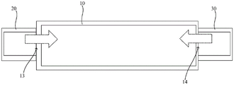
图1为本公开一实施例的传输腔室的结构示意图;FIG. 1 is a schematic structural diagram of a transfer chamber according to an embodiment of the disclosure;
图2为本公开一实施例的传输腔室的出风部的俯视结构图;2 is a top structural view of an air outlet of a transmission chamber according to an embodiment of the disclosure;
图3为图2在A-A处的剖视结构示意图;Fig. 3 is the sectional structure schematic diagram of Fig. 2 at A-A place;
图4为图2在B-B处的剖视结构示意图;Fig. 4 is the sectional structure schematic diagram at B-B place of Fig. 2;
图5为本公开另一实施例的传输腔室的结构示意图;FIG. 5 is a schematic structural diagram of a transfer chamber according to another embodiment of the disclosure;
图6为图5在C-C处的剖视结构示意图。FIG. 6 is a schematic cross-sectional structural diagram at C-C of FIG. 5 .
10、腔体;1101、第一出风部;1102、第二出风部;111、凸部;1111、第一壁面;1112、第二壁面;1113、出风口;1114、风道;1115、控制气阀;12、排废孔;13、第一连接口;14、第二连接口;15、支撑部;16、抽气孔;17、充气孔;20、工艺腔室;30、大气传送模块。10, cavity; 1101, first air outlet; 1102, second air outlet; 111, convex part; 1111, first wall surface; 1112, second wall surface; 1113, air outlet; 1114, air duct; 1115, Control air valve; 12, waste discharge hole; 13, first connection port; 14, second connection port; 15, support part; 16, air suction hole; 17, gas filling hole; 20, process chamber; .
具体实施方式Detailed ways
为使本公开的上述目的、特征和优点能够更加明显易懂,下面结合附图对本公开的具体实施方式做详细的说明。在下面的描述中阐述了很多具体细节以便于充分理解本公开。但是本公开能够以很多不同于在此描述的其它方式来实施,本领域技术人员可以在不违背本公开内涵的情况下做类似改进,因此本公开不受下面公开的具体实施例的限制。In order to make the above objects, features and advantages of the present disclosure more clearly understood, the specific embodiments of the present disclosure will be described in detail below with reference to the accompanying drawings. In the following description, numerous specific details are set forth in order to provide a thorough understanding of the present disclosure. However, the present disclosure can be implemented in many other ways different from those described herein, and those skilled in the art can make similar improvements without departing from the connotation of the present disclosure. Therefore, the present disclosure is not limited by the specific embodiments disclosed below.
正如背景技术所述,现有技术中的传输腔室的清洁操作工作效率较低,清洁操作的维护成本较高问题,经发明人研究发现,出现这种问题的原因在于,清洁真空传输腔室时必须要对真空传输腔室进行开腔处理,然后人工手动例如采用压缩干燥空气的气枪对真空传输腔室的内壁进行吹扫清理。As mentioned in the background art, the cleaning operation of the transfer chamber in the prior art has low work efficiency, and the maintenance cost of the cleaning operation is relatively high. The inventors have found that the reason for this problem is that cleaning the vacuum transfer chamber When it is necessary to open the vacuum transmission chamber, the inner wall of the vacuum transmission chamber must be cleaned manually, for example, by using an air gun with compressed dry air.
基于以上原因,本公开提供一种传输腔室与半导体加工设备,它能够提高工作效率,降低清洁维护成本。Based on the above reasons, the present disclosure provides a transfer chamber and semiconductor processing equipment, which can improve work efficiency and reduce cleaning and maintenance costs.
参阅图1,图1示出了本公开一实施例的传输腔室的结构示意图,本公开一实施例提供的一种传输腔室,传输腔室包括但不限于为真空传输腔室,例如还可以是其它功能的传输腔室,本实施例中将具体以真空传输腔室为例进行展开。传输腔室包括腔体10。腔体10的内壁上设有至少两个出风部。出风部用于向腔体10内部输出清扫气体。至少两个出风部沿着环绕腔体10的中心轴线的方向(例如图1所示的虚线箭头所示的方向)依次间隔布置。腔体10的底部开设有与腔体10外部相连通的排废孔12,排废孔12用于与负压器件(图中未示出)连通。Referring to FIG. 1, FIG. 1 shows a schematic structural diagram of a transfer chamber according to an embodiment of the present disclosure. An embodiment of the present disclosure provides a transfer chamber. The transfer chamber includes, but is not limited to, a vacuum transfer chamber, such as a It can be a transfer chamber with other functions, and in this embodiment, a vacuum transfer chamber will be used as an example for development. The transfer chamber includes a
需要说明的是,中心轴线为如图1的点Z所示。It should be noted that the central axis is as indicated by point Z in FIG. 1 .
上述的传输腔室,由于在腔体10的内壁上设置有至少两个出风部,且至少两个出风部沿着环绕腔体10的中心轴线方向依次间隔设置,这样在对腔体10内部启动清洁工作时,各个出风部向腔体10内部通入清扫气体,能在腔体10内产生涡流现象,并形成回旋气流,对腔体10内部进行清洁,气流能带走颗粒杂质等异物;当异物经过腔体10底部的排废孔12时,负压器件工作,便能通过排废孔12抽出到腔体10的外部。如此,便能实现在不开腔的前提下进行传输腔室的自动清洁,能提高清洁预防维护的效率,大大降低维护成本。The above-mentioned transmission chamber, because at least two air outlet parts are provided on the inner wall of the
具体而言,清扫气体包括但不限于为CDA(Compressor Dry Air压缩干燥空气)气体,该CAD气体能实现对腔体10内部较好的清洁效果,同时成本较为低廉,绿色无污染。当然,清扫气体还可以选用例如氮气等等其它各种类型的气体,具体如何选取在此不进行限定,可以根据实际需求灵活调整与设置,只要能对腔体10内部的异物起到清洁作用即可。Specifically, the cleaning gas includes, but is not limited to, CDA (Compressor Dry Air) gas. The CAD gas can achieve a better cleaning effect on the interior of the
请参阅图1,在一个实施例中,各个出风部出风时的出风方向均为沿着环绕中心轴线的逆时针方向(如图1中箭头所示的方向)设置或者均为沿着环绕中心轴线的顺时针方向设置。如此,各个出风部均沿着同一时针方向出风,能有利于在腔体10内产生涡流现象,并形成回旋气流,从而能保证腔体10内部的清洁效果。Referring to FIG. 1 , in one embodiment, the air outlet directions of each air outlet part are set along the counterclockwise direction around the central axis (the direction shown by the arrow in FIG. 1 ) or are along the direction of the center axis. Clockwise setting around the central axis. In this way, each air outlet part emits air in the same clockwise direction, which can help to generate a vortex phenomenon in the
请参阅图1、图5与图6,图5示意出了本公开另一实施例的传输腔室的结构示意图,图6示意出了图5在C-C处的剖视结构示意图。图5相对于图1而言,主要区别在于,图5中所示的工艺腔室20的数量明显多于图1,图5中还示意出了大气传送模块30。作为一些示例,腔体10外部还连接有例如工艺腔室20和/或大气传送模块30。需要说明的是,工艺腔室20的数量不限于图1中的1个,可以例如为1-5个,具体数量可以根据实际需求灵活调整与设置,在此不进行限定。此外,大气传送模块30也不限于如图6中的为1个,具体设置数量可以根据实际需求灵活调整与设置。Please refer to FIG. 1 , FIG. 5 and FIG. 6 , FIG. 5 is a schematic structural diagram of a transfer chamber according to another embodiment of the present disclosure, and FIG. 6 is a schematic cross-sectional structural diagram of FIG. 5 at C-C. The main difference between FIG. 5 and FIG. 1 is that the number of
请参阅图6,在一个实施例中,腔体10的内壁上设有用于与工艺腔室20连通的第一连接口13,和/或用于与大气传送模块30连通的第二连接口14。如此,除了利用到涡旋气流对腔体10内壁的吹拂清扫外,还利用到了气体流速形成的压力差来实现将与真空传输腔室连通的其它腔室内部的异物向外抽出,从而能实现对其它腔室高效高质的清洗效果。Referring to FIG. 6 , in one embodiment, the inner wall of the
具体而言,在真空传输腔室的腔体10内部形成环形气流的同时,由于流速形成压力差,工艺腔室20内部的异物可以通过第一连接口13抽吸到真空传输腔室内部,以及大气传送模块30内部的异物通过第二连接口14抽吸到真空传输腔室内部,相较于人为手动的用CDA gun吹扫效率更高,清洁效果更好。Specifically, while the annular airflow is formed inside the
请参阅图6,在一个实施例中,出风部包括第一出风部1101,第一出风部1101位于第一连接口13侧部部位并朝向第一连接口13出风。和/或,出风部包括第二出风部1102,第二出风部1102位于第二连接口14侧部部位并朝向第二连接口14出风。如此,位于第一连接口13侧部部位的第一出风部1101出风时,第一出风部1101的出风方向朝向第一连接口13,在经过第一连接口13的过程中,气体流速形成的压力差明显,能实现工艺腔室20内部的异物通过第一连接口13抽吸到真空传输腔室内部;同样地,位于第二连接口14侧部部位的第二出风部1102出风时,第二出风部1102的出风方向朝向第二连接口14,在经过第二连接口14的过程中,气体流速形成的压力差明显,能实现工艺腔室20内部的异物通过第二连接口14抽吸到真空传输腔室内部。Referring to FIG. 6 , in one embodiment, the air outlet includes a
经研究发现,在一个实施例中,第一出风部1101与第一连接口13侧边沿的间距例如控制在20cm以内,具体例如为5cm-15cm,便能保证第一出风部1101的风在经过第一连接口13的过程中,气体流速形成的压力差明显,以保证对工艺腔室20内部的异物的较好清洁效果。同样地,第二出风部1102与第二连接口14侧边沿的间距例如控制在20cm以内,具体例如为5cm-15cm,便能保证第二出风部1102的风在经过第二连接口14的过程中,气体流速形成的压力差明显,以保证对大气传送模块30内部的异物的较好清洁效果。Through research, it is found that, in one embodiment, the distance between the
当然,在一些可选的实施例中,也可以无需在第一连接口13的侧部部位设置第一出风部1101,以及无需在第二连接口14的侧部部位设置第二出风部1102,而是例如将出风部设置于远离于第一连接口13的位置,以及远离于第二连接口14的位置。当各个出风部的气压足够大,以及出风部的数量足够多时,各个出风部向腔体10内部通入清扫气体的过程中,能在腔体10内产生足够明显的涡流现象,并形成足够强的回旋气流,这样回旋气流经过第一连接口13的位置与第二连接口14的位置时,同样能在第一连接口13处形成明显的气体流速压力差,以保证对工艺腔室20内部的异物的较好清洁效果;以及能在第二连接口14处形成明显的气体流速压力差,以保证对大气传送模块30内部异物的较好清洁效果。Of course, in some optional embodiments, the
请参阅图1,在一个实施例中,至少两个出风部等间隔地布置于腔体10的内壁上。如此,当出风部等间隔地布置于腔体10的内壁上时,能实现对腔体10内部较好的清洁效果。当然,作为一些可选的方案,各个出风部在腔体10内壁上的布置方式也可以是不等间隔的,具体各个相邻出风部的间隔大小如何设定,可以根据实际需求灵活调整与设置,在此不进行限定。Referring to FIG. 1 , in one embodiment, at least two air outlet parts are arranged on the inner wall of the
请参阅图1,在一个实施例中,出风部的数量为3个至15个。Referring to FIG. 1 , in one embodiment, the number of air outlet parts is 3 to 15.
在一些实施例中,出风部的数量例如设为3个、5个、6个、7个、8个、13个或15个。当然,作为一些可选的方案,出风部的数量也可以设置为2个或15个以上,具体设置数量在此不进行限定,可以根据实际需求灵活地调整。In some embodiments, the number of air outlet parts is set to 3, 5, 6, 7, 8, 13 or 15, for example. Of course, as some optional solutions, the number of air outlet parts can also be set to 2 or more than 15, and the specific number is not limited here, and can be flexibly adjusted according to actual needs.
经研究发现,当将出风部的数量设置为5个-7个时,便能满足对腔体10内部的清洁效果,同时出风部的数量不至于过多而导致传输腔室的结构复杂化。After research, it is found that when the number of air outlets is set to 5 to 7, the cleaning effect on the interior of the
请参阅图1至图4,图2示出了本公开一实施例的传输腔室的出风部的俯视结构图,图3示出了图2在A-A处的剖视结构示意图,图4示出了图2在B-B处的剖视结构示意图。在一个实施例中,出风部包括设置于腔体10内壁上或者由腔体10内壁朝向中心轴线的方向延伸形成的凸部111。凸部111包括面向于中心轴线的第一壁面1111以及分别连接于第一壁面1111相对两侧的两个第二壁面1112,至少其中一个第二壁面1112上设置有至少一个出风口1113。如此,出风部通过出风口1113向腔体10内部输出清扫气体,出风口1113由于位于第二壁面1112上,这样当至少两个出风部同时出风时,能有利于在腔体10内产生涡流现象,并形成回旋气流,对腔体10内部进行清洁效果较好。Please refer to FIG. 1 to FIG. 4 , FIG. 2 shows a top view of the air outlet of the transmission chamber according to an embodiment of the present disclosure, FIG. 3 shows a schematic cross-sectional view of FIG. A schematic diagram of the cross-sectional structure at B-B in FIG. 2 is shown. In one embodiment, the air outlet includes a
可选地,凸部111的两个第二壁面1112例如相对平行设置或大体上平行设置。其中,“大体平行”并非数学意义上严格的“平行”,而是肉眼看上去相互“平行”即可。Optionally, the two second wall surfaces 1112 of the
可选地,第二壁面1112的延伸经过中心轴线,或者与中心轴线存在预设范围内的偏差量,该预设范围为根据实际情况灵活控制与调整,例如控制在1cm-5cm以内。Optionally, the extension of the
此外,当凸部111的两个第二壁面1112上均设有出风口1113时,在工作过程中,为了保证腔体10内部的气流涡旋效果,需要使各个凸部111的出风口1113均同步在腔体10内部按照逆时针的方向出风或者均同步按照顺时针方向出风,也即各个凸部111均采取其上游位置的第二壁面1112上的出风口1113出风或均采取其下游位置的第二壁面1112上的出风口1113出风,另一个第二壁面1112上的出风口1113停止。需要说明的是,该上游位置的第二壁面1112指的是例如以绕中心轴线的顺时针方向为参照,凸部111上第一个位置的第二壁面1112为上游位置,另一个第二壁面1112相应为下游位置。In addition, when the two second wall surfaces 1112 of the
另外,当凸部111的其中一个第二壁面1112上设置有出风口1113时,为了保证腔体10内部的气流涡旋效果,各个凸部111都是在上游位置的第二壁面1112上设置有出风口1113,这样便能实现在腔体10内部按照逆时针方向出风;或者,各个凸部111都是下游位置的第二壁面1112上设置有出风口1113,这样便能实现在腔体10内部按照顺时针方向出风。In addition, when one of the second wall surfaces 1112 of the
当然,作为一些可选的方案,其中一个或多个凸部111的两个壁面上均设置有出风口1113,其余凸部111的只有一个壁面上设置出风口1113。Of course, as some optional solutions, one or more
请参阅图1至图4,在一个实施例中,凸部111的两个第二壁面1112均设有出风口1113,且凸部111的两个第二壁面1112的出风口1113相互连通形成风道1114,风道1114内设有用于控制其中一个出风口1113出风的控制气阀1115,控制气阀1115用于与清扫气体提供装置相连。如此,清扫气体提供装置将气体输送给控制气阀1115后,控制气阀1115能将清扫气体选择性地从其中一个第二壁面1112上的出风口1113向外排出到腔体10内部。Referring to FIGS. 1 to 4 , in one embodiment, the two
请参阅图1至图4,在一个实施例中,第一壁面1111为弧形面,弧形面的圆心位于弧形面背离于中心轴线的一侧。如此,一方面,第一壁面1111能便于气流流动,能减小风阻,便于在腔体10内部形成涡旋气流;另一方面,腔体10的内壁无死角,能便于清理掉腔体10内部的异物。Referring to FIGS. 1 to 4 , in one embodiment, the
具体而言,弧形面既可以是圆弧形面,又可以是椭圆弧形面。当然,作为一些可选的方案,第一壁面1111还可以是设计成其它形状,即不限于是弧形面,例如可以是方形、三角形、五边形、六边形等等规则形状与不规则形状,具体可以根据实际需求灵活地调整与设置,在此不进行限定。Specifically, the arc-shaped surface may be either a circular arc-shaped surface or an elliptical arc-shaped surface. Of course, as some optional solutions, the
请参阅图2至图4,在一个实施例中,第二壁面1112上沿着竖向方向上依次间隔设置有多个出风口1113。如此,各个凸部111的不同高度位置处的出风口1113可以同步出风,也可以自由组合选择性地出风,从而能在沿着竖向方向上形成上中下不同层次的气流,进而能实现对腔体10内部的较好的清洁效果。Referring to FIGS. 2 to 4 , in one embodiment, a plurality of
请参阅图3与图4,在一个实施例中,第二壁面1112上的多个出风口1113包括但不限于以等间隔的方式布置,还可以是以不等间隔的方式,具体可以根据实际需求设置。Please refer to FIG. 3 and FIG. 4 , in one embodiment, the plurality of
请参阅图3与图4,在一个实施例中,第二壁面1112上的相邻两个出风口1113的间隔为5cm-20cm。具体而言,第二壁面1112上相邻两个出风口1113的间隔为5cm-10cm。如此,经过研究发现,将出风口1113的间隔设置在该范围时,能保证对腔体10在沿着竖向方向上形成上中下不同层次的气流,进而能实现对腔体10内部的较好的清洁效果。Referring to FIG. 3 and FIG. 4 , in one embodiment, the interval between two
请参阅图3与图4,在一个实施例中,第二壁面1112上的出风口1113的数量包括但不限于为2个-10个。当然,还可以是设置为1个以及大于10个的数量,具体如何设置,可以根据实际需求灵活调整与选取,在此不进行限定。Referring to FIG. 3 and FIG. 4 , in one embodiment, the number of
经研究发现,当将第二壁面1112上的出风口1113数量为4个-6个时,便能满足对腔体10内部沿着竖向方向上的各个部位的清洁效果,同时出风口1113的数量不至于过多而导致传输腔室的结构复杂化。It is found through research that when the number of
请参阅图1,在一个实施例中,腔体10底部的中部位置设有支撑部15,支撑部15设有机械手,机械手用于传输基片。其中,基片包括但不限于为半导体工件,具体例如为晶圆。Referring to FIG. 1 , in one embodiment, a
请参阅图1,在一个实施例中,腔体10的壁上设有用于与真空泵相连通的抽气孔16以及与充气装置相连通的充气孔17。如此,通过抽气孔16可以将腔体10进行抽真空处理,使得腔体10的真空度符合于工艺的预设要求。此外,通过充气孔17可以给腔体10进行充气处理,使得腔体10充气到大气。Referring to FIG. 1 , in one embodiment, the wall of the
在一个实施例中,一种采用上述任一实施例的传输腔室的清洁方法,清洁方法包括如下步骤:In one embodiment, a method for cleaning a transfer chamber using any of the above embodiments, the cleaning method includes the following steps:
步骤S100、通过至少两个出风部向腔体10内部通入清扫气体,使得在腔体10内部形成涡旋气流,通过涡旋气流清扫去除腔体10内部的异物;In step S100, the cleaning gas is introduced into the
步骤S200、通过排废孔12将腔体10内部的含有异物的清扫气体向外抽出。In step S200 , the cleaning gas containing foreign matter inside the
上述的清洁方法,能实现在不开腔的前提下进行传输腔室的自动清洁,能提高清洁预防维护的效率,大大降低维护成本。The above cleaning method can realize automatic cleaning of the transmission chamber without opening the chamber, improve the efficiency of cleaning and preventive maintenance, and greatly reduce the maintenance cost.
在一个实施例中,清洁方法还包括步骤S300:通过涡旋气流的流速形成压差,将工艺腔室20内部的异物通过第一连接口13抽吸到真空传输腔室内部,和/或,将大气传送模块30内部的异物通过第二连接口14抽吸到真空传输腔室内部。In one embodiment, the cleaning method further includes step S300: forming a pressure difference through the flow rate of the vortex air flow, and sucking the foreign matter inside the
在一个实施例中,在步骤S100中,可以根据对腔体10内部的清洁效果来调整气体压力大小,以使得气体压力调整到合适值,避免气体压力过大导致气体浪费。In one embodiment, in step S100, the gas pressure may be adjusted according to the cleaning effect on the inside of the
在一个实施例中,在步骤S100中,既可以采用持续性地方式向腔体10内部通入恒定压力的清扫气体,又可以是采用脉冲式地方式向腔体10内部通入恒定压力或变化压力的清扫气体,具体方式例如为每1秒-3秒停顿一次,并通入10秒-30秒的清扫气体。当然,具体气体压力的控制大小以及通入气体的操作方式可以根据实际需求灵活调整与设置,在此不进行限定。In one embodiment, in step S100 , the cleaning gas of constant pressure may be introduced into the
在一个实施例中,在步骤S100中,在对腔体10内部进行清洁操作时,既可以是使得各个出风部的出风方向均按照逆时针的方向进入到腔体10内部,又可以是使得各个出风部的出风方向均按照顺时针的方向进入到腔体10内部,还可以是先按照逆时针的方向进入到腔体10内部,然后又按照顺时针的方向进入到腔体10内部。当然,还可以是采取其它方式将清扫气体通入到腔体10内部,具体如何选取可以根据实际需求灵活调整与设置,在此不进行限定。In one embodiment, in step S100 , when cleaning the inside of the
请参阅图1至图4,在一个实施例中,一种半导体加工设备,半导体加工设备包括上述任一实施例的传输腔室。Referring to FIGS. 1 to 4 , in one embodiment, a semiconductor processing apparatus includes the transfer chamber of any of the above-described embodiments.
上述的半导体加工设备,由于在腔体10的内壁上设置有至少两个出风部,且至少两个出风部沿着环绕腔体10的中心轴线方向依次间隔设置,这样在对腔体10内部启动清洁工作时,各个出风部向腔体10内部通入清扫气体,能在腔体10内产生涡流现象,并形成回旋气流,对腔体10内部进行清洁,气流能带走颗粒杂质等异物;当异物经过腔体10底部的排废孔12时,负压器件工作,便能通过排废孔12抽出到腔体10的外部。如此,便能实现在不开腔的前提下进行传输腔室的自动清洁,能提高清洁预防维护的效率,大大降低维护成本。The above-mentioned semiconductor processing equipment, since at least two air outlet parts are provided on the inner wall of the
请参阅图1至图4,在一个实施例中,半导体加工设备还包括清扫气体提供装置(图中未示出)。清扫气体提供装置分别与各个出风部相连通。Referring to FIGS. 1 to 4 , in one embodiment, the semiconductor processing equipment further includes a purge gas supply device (not shown in the figures). The cleaning gas supply devices are respectively communicated with each air outlet.
具体而言,清扫气体提供装置设有多个输气管道。多个输气管道分别与多个出风部对应连通。如此,通过多个输气管道能将清扫气体分别输出给多个出风部,由出风部将清扫气体通入到腔体10内部。Specifically, the purge gas supply device is provided with a plurality of gas transmission pipes. The plurality of gas transmission pipes are respectively communicated with the plurality of air outlet parts correspondingly. In this way, the cleaning gas can be output to the plurality of air outlet parts respectively through the plurality of gas transmission pipelines, and the air outlet parts can pass the cleaning gas into the
可选地,清扫气体提供装置例如还包括多通流量控制阀,通过多通流量控制阀分别与多个输气管道相连,这样便能够控制调整各个输气管道是否通气以及通入的气体流量大小。当然,作为一个示例,多通流量控制阀也可以替换成分别设置于各个输气管道上的多个流量调节阀。Optionally, the scavenging gas supply device, for example, further includes a multi-pass flow control valve, which is respectively connected with a plurality of gas transmission pipelines through the multi-pass flow control valve, so that it is possible to control and adjust whether each gas transmission pipeline is ventilated and the flow rate of the gas introduced. . Of course, as an example, the multi-pass flow control valve can also be replaced with a plurality of flow control valves respectively disposed on each gas pipeline.
通过对各个出风部的气体流量大小进行调整,能相应调整腔体10内部的气流涡旋状态,从而能起到改善对腔体10内部的清洁效果的作用。此外,还能避免清扫气体的通入流量过大而导致气体浪费,以及避免清扫气体的通入流量过小而达不到对腔体10内部的清洁效果。By adjusting the gas flow rate of each air outlet, the vortex state of the air flow inside the
在一个实施例中,半导体加工设备还包括异物收集装置(图中未示出)。异物收集装置设有负压器件。如此,异物收集装置工作时,负压器件提供负压将腔体10内部的异物通过排废孔12向外抽出,以及通过异物收集装置进行收集,异物收集装置将异物收集后集中处理。In one embodiment, the semiconductor processing equipment further includes a foreign material collection device (not shown in the figures). The foreign matter collection device is provided with a negative pressure device. In this way, when the foreign matter collection device is in operation, the negative pressure device provides negative pressure to draw out the foreign matter inside the
具体而言,异物收集装置位于腔体10的外部。Specifically, the foreign matter collection device is located outside the
以上所述实施例的各技术特征可以进行任意的组合,为使描述简洁,未对上述实施例中的各个技术特征所有可能的组合都进行描述,然而,只要这些技术特征的组合不存在矛盾,都应当认为是本说明书记载的范围。The technical features of the above-described embodiments can be combined arbitrarily. For the sake of brevity, all possible combinations of the technical features in the above-described embodiments are not described. However, as long as there is no contradiction between the combinations of these technical features, All should be regarded as the scope described in this specification.
以上所述实施例仅表达了本公开的几种实施方式,其描述较为具体和详细,但并不能因此而理解为对公开专利范围的限制。应当指出的是,对于本领域的普通技术人员来说,在不脱离本公开构思的前提下,还可以做出若干变形和改进,这些都属于本公开的保护范围。因此,本公开专利的保护范围应以所附权利要求为准。The above-mentioned embodiments only represent several embodiments of the present disclosure, and the descriptions thereof are relatively specific and detailed, but should not be construed as a limitation on the scope of the disclosed patent. It should be noted that, for those skilled in the art, without departing from the concept of the present disclosure, several modifications and improvements can be made, which all belong to the protection scope of the present disclosure. Accordingly, the scope of protection of the present disclosure should be determined by the appended claims.
在本公开的描述中,需要理解的是,术语“中心”、“纵向”、“横向”、“长度”、“宽度”、“厚度”、“上”、“下”、“前”、“后”、“左”、“右”、“竖直”、“水平”、“顶”、“底”、“内”、“外”、“顺时针”、“逆时针”、“轴向”、“径向”、“周向”等指示的方位或位置关系为基于附图所示的方位或位置关系,仅是为了便于描述本公开和简化描述,而不是指示或暗示所指的装置或元件必须具有特定的方位、以特定的方位构造和操作,因此不能理解为对本公开的限制。In the description of the present disclosure, it is to be understood that the terms "center", "longitudinal", "lateral", "length", "width", "thickness", "upper", "lower", "front", " Back, Left, Right, Vertical, Horizontal, Top, Bottom, Inner, Outer, Clockwise, Counterclockwise, Axial , "radial", "circumferential" and other indicated orientations or positional relationships are based on the orientations or positional relationships shown in the accompanying drawings, and are only for the convenience of describing the present disclosure and simplifying the description, rather than indicating or implying the indicated device or Elements must have a particular orientation, be constructed, and operate in a particular orientation and are therefore not to be construed as limitations of the present disclosure.
此外,术语“第一”、“第二”仅用于描述目的,而不能理解为指示或暗示相对重要性或者隐含指明所指示的技术特征的数量。由此,限定有“第一”、“第二”的特征可以明示或者隐含地包括至少一个该特征。在本公开的描述中,“多个”的含义是至少两个,例如两个,三个等,除非另有明确具体的限定。In addition, the terms "first" and "second" are only used for descriptive purposes, and should not be construed as indicating or implying relative importance or implying the number of indicated technical features. Thus, a feature delimited with "first", "second" may expressly or implicitly include at least one of that feature. In the description of the present disclosure, "plurality" means at least two, such as two, three, etc., unless expressly and specifically defined otherwise.
在本公开中,除非另有明确的规定和限定,术语“安装”、“相连”、“连接”、“固定”等术语应做广义理解,例如,可以是固定连接,也可以是可拆卸连接,或成一体;可以是机械连接,也可以是电连接;可以是直接相连,也可以通过中间媒介间接相连,可以是两个元件内部的连通或两个元件的相互作用关系,除非另有明确的限定。对于本领域的普通技术人员而言,可以根据具体情况理解上述术语在本公开中的具体含义。In the present disclosure, unless otherwise expressly specified and limited, the terms "installed", "connected", "connected", "fixed" and other terms should be understood in a broad sense, for example, it may be a fixed connection or a detachable connection , or integrated; it can be a mechanical connection or an electrical connection; it can be directly connected or indirectly connected through an intermediate medium, it can be the internal connection of two elements or the interaction relationship between the two elements, unless otherwise specified limit. For those of ordinary skill in the art, the specific meanings of the above terms in the present disclosure can be understood according to specific situations.
在本公开中,除非另有明确的规定和限定,第一特征在第二特征“上”或“下”可以是第一和第二特征直接接触,或第一和第二特征通过中间媒介间接接触。而且,第一特征在第二特征“之上”、“上方”和“上面”可是第一特征在第二特征正上方或斜上方,或仅仅表示第一特征水平高度高于第二特征。第一特征在第二特征“之下”、“下方”和“下面”可以是第一特征在第二特征正下方或斜下方,或仅仅表示第一特征水平高度小于第二特征。In the present disclosure, unless expressly stated and defined otherwise, a first feature "on" or "under" a second feature may be in direct contact with the first and second features, or indirectly through an intermediary between the first and second features touch. Also, the first feature being "above", "over" and "above" the second feature may mean that the first feature is directly above or obliquely above the second feature, or simply means that the first feature is level higher than the second feature. The first feature being "below", "below" and "below" the second feature may mean that the first feature is directly or obliquely below the second feature, or simply means that the first feature has a lower level than the second feature.
需要说明的是,当元件被称为“固定于”或“设置于”另一个元件,它可以直接在另一个元件上或者也可以存在居中的元件。当一个元件被认为是“连接”另一个元件,它可以是直接连接到另一个元件或者可能同时存在居中元件。本文所使用的术语“垂直的”、“水平的”、“上”、“下”、“左”、“右”以及类似的表述只是为了说明的目的,并不表示是唯一的实施方式。It should be noted that when an element is referred to as being "fixed to" or "disposed on" another element, it can be directly on the other element or an intervening element may also be present. When an element is referred to as being "connected" to another element, it can be directly connected to the other element or intervening elements may also be present. The terms "vertical", "horizontal", "upper", "lower", "left", "right" and similar expressions used herein are for the purpose of illustration only and do not represent the only embodiment.
Claims (16)
Priority Applications (1)
| Application Number | Priority Date | Filing Date | Title |
|---|---|---|---|
| CN202210934350.XA CN115228862B (en) | 2022-08-04 | 2022-08-04 | Transmission chamber, cleaning method thereof and semiconductor processing equipment |
Applications Claiming Priority (1)
| Application Number | Priority Date | Filing Date | Title |
|---|---|---|---|
| CN202210934350.XA CN115228862B (en) | 2022-08-04 | 2022-08-04 | Transmission chamber, cleaning method thereof and semiconductor processing equipment |
Publications (2)
| Publication Number | Publication Date |
|---|---|
| CN115228862A true CN115228862A (en) | 2022-10-25 |
| CN115228862B CN115228862B (en) | 2023-10-17 |
Family
ID=83679975
Family Applications (1)
| Application Number | Title | Priority Date | Filing Date |
|---|---|---|---|
| CN202210934350.XA Active CN115228862B (en) | 2022-08-04 | 2022-08-04 | Transmission chamber, cleaning method thereof and semiconductor processing equipment |
Country Status (1)
| Country | Link |
|---|---|
| CN (1) | CN115228862B (en) |
Citations (10)
| Publication number | Priority date | Publication date | Assignee | Title |
|---|---|---|---|---|
| US5616208A (en) * | 1993-09-17 | 1997-04-01 | Tokyo Electron Limited | Vacuum processing apparatus, vacuum processing method, and method for cleaning the vacuum processing apparatus |
| US20030054299A1 (en) * | 1998-12-01 | 2003-03-20 | Kotaro Kawamura | Waste gas treatment system |
| KR20070054311A (en) * | 2005-11-23 | 2007-05-29 | 삼성전자주식회사 | Semiconductor manufacturing equipment |
| WO2014073460A1 (en) * | 2012-11-07 | 2014-05-15 | 東京エレクトロン株式会社 | Substrate cooling member, substrate processing device, and substrate processing method |
| US20150273659A1 (en) * | 2014-03-31 | 2015-10-01 | Ebara Corporation | Substrate polishing apparatus |
| CN208613290U (en) * | 2018-05-31 | 2019-03-19 | 梁献伟 | Prevention and control device for gas heating and accelerating dust deposition and crystallization |
| US20200075363A1 (en) * | 2018-08-29 | 2020-03-05 | Samsung Electronics Co., Ltd. | Semiconductor package molding device and method of manufacturing semiconductor device |
| CN111545053A (en) * | 2020-05-14 | 2020-08-18 | 中国科学院过程工程研究所 | Vortex type soot blowing assembly, SCR reaction device comprising same and method |
| CN112530831A (en) * | 2019-09-19 | 2021-03-19 | 夏泰鑫半导体(青岛)有限公司 | Semiconductor device and semiconductor device cleaning method |
| CN214263045U (en) * | 2020-12-24 | 2021-09-24 | 国电汉川发电有限公司 | Blowing, sucking and dust removing device of sampling machine |
-
2022
- 2022-08-04 CN CN202210934350.XA patent/CN115228862B/en active Active
Patent Citations (10)
| Publication number | Priority date | Publication date | Assignee | Title |
|---|---|---|---|---|
| US5616208A (en) * | 1993-09-17 | 1997-04-01 | Tokyo Electron Limited | Vacuum processing apparatus, vacuum processing method, and method for cleaning the vacuum processing apparatus |
| US20030054299A1 (en) * | 1998-12-01 | 2003-03-20 | Kotaro Kawamura | Waste gas treatment system |
| KR20070054311A (en) * | 2005-11-23 | 2007-05-29 | 삼성전자주식회사 | Semiconductor manufacturing equipment |
| WO2014073460A1 (en) * | 2012-11-07 | 2014-05-15 | 東京エレクトロン株式会社 | Substrate cooling member, substrate processing device, and substrate processing method |
| US20150273659A1 (en) * | 2014-03-31 | 2015-10-01 | Ebara Corporation | Substrate polishing apparatus |
| CN208613290U (en) * | 2018-05-31 | 2019-03-19 | 梁献伟 | Prevention and control device for gas heating and accelerating dust deposition and crystallization |
| US20200075363A1 (en) * | 2018-08-29 | 2020-03-05 | Samsung Electronics Co., Ltd. | Semiconductor package molding device and method of manufacturing semiconductor device |
| CN112530831A (en) * | 2019-09-19 | 2021-03-19 | 夏泰鑫半导体(青岛)有限公司 | Semiconductor device and semiconductor device cleaning method |
| CN111545053A (en) * | 2020-05-14 | 2020-08-18 | 中国科学院过程工程研究所 | Vortex type soot blowing assembly, SCR reaction device comprising same and method |
| CN214263045U (en) * | 2020-12-24 | 2021-09-24 | 国电汉川发电有限公司 | Blowing, sucking and dust removing device of sampling machine |
Also Published As
| Publication number | Publication date |
|---|---|
| CN115228862B (en) | 2023-10-17 |
Similar Documents
| Publication | Publication Date | Title |
|---|---|---|
| CN105280523B (en) | Substrate processing apparatus and method | |
| CN210378981U (en) | Wafer Processing Equipment | |
| CN107574422A (en) | Semiconductor production equipment and its cleaning method | |
| CN108962713B (en) | A process chamber and semiconductor processing equipment | |
| CN104241174B (en) | The blowing method of film magazine chamber, plasma processing device and film magazine chamber | |
| CN107346757A (en) | Transmission chamber and semiconductor processing equipment | |
| CN115228862A (en) | Transfer chamber and cleaning method thereof, semiconductor processing equipment | |
| CN218855041U (en) | Solar cell production equipment, dust removal assembly and air knife | |
| WO2024139981A1 (en) | Load lock chamber and cleaning method therefor, and semiconductor device | |
| CN107093544B (en) | Pre-cleaning cavity and semiconductor processing equipment | |
| CN112530831B (en) | Semiconductor device and semiconductor device cleaning method | |
| CN113945072A (en) | Drying system and drying method | |
| TWI857521B (en) | Vacuum treatment device | |
| CN114256086A (en) | Gas path system of semiconductor reaction chamber, control method and processing equipment | |
| CN119255682A (en) | Perovskite crystallization device | |
| CN113327875B (en) | Vertical heat treatment equipment | |
| CN111834247A (en) | Cooling units and semiconductor processing equipment | |
| CN111330735B (en) | Powder collection system | |
| CN109719071B (en) | Wafer cleaning dryer | |
| TWI911604B (en) | Loading chamber and cleaning method thereof, and semiconductor equipment | |
| CN220836987U (en) | RPS cavity maintenance operation device | |
| JP7031131B2 (en) | EFEM and EFEM gas replacement method | |
| CN219547090U (en) | Gas delivery device and semiconductor device | |
| CN221608185U (en) | Semiconductor deposition equipment | |
| CN221116008U (en) | Filling device of resin storage tank |
Legal Events
| Date | Code | Title | Description |
|---|---|---|---|
| PB01 | Publication | ||
| PB01 | Publication | ||
| SE01 | Entry into force of request for substantive examination | ||
| SE01 | Entry into force of request for substantive examination | ||
| GR01 | Patent grant | ||
| GR01 | Patent grant |