CN111545053A - Vortex type soot blowing assembly, SCR reaction device comprising same and method - Google Patents
Vortex type soot blowing assembly, SCR reaction device comprising same and method Download PDFInfo
- Publication number
- CN111545053A CN111545053A CN202010407842.4A CN202010407842A CN111545053A CN 111545053 A CN111545053 A CN 111545053A CN 202010407842 A CN202010407842 A CN 202010407842A CN 111545053 A CN111545053 A CN 111545053A
- Authority
- CN
- China
- Prior art keywords
- compressed air
- blowing
- flue
- soot
- shell
- Prior art date
- Legal status (The legal status is an assumption and is not a legal conclusion. Google has not performed a legal analysis and makes no representation as to the accuracy of the status listed.)
- Pending
Links
Images


Classifications
-
- B—PERFORMING OPERATIONS; TRANSPORTING
- B01—PHYSICAL OR CHEMICAL PROCESSES OR APPARATUS IN GENERAL
- B01D—SEPARATION
- B01D53/00—Separation of gases or vapours; Recovering vapours of volatile solvents from gases; Chemical or biological purification of waste gases, e.g. engine exhaust gases, smoke, fumes, flue gases, aerosols
- B01D53/34—Chemical or biological purification of waste gases
- B01D53/74—General processes for purification of waste gases; Apparatus or devices specially adapted therefor
- B01D53/86—Catalytic processes
- B01D53/8621—Removing nitrogen compounds
- B01D53/8625—Nitrogen oxides
- B01D53/8631—Processes characterised by a specific device
-
- B—PERFORMING OPERATIONS; TRANSPORTING
- B01—PHYSICAL OR CHEMICAL PROCESSES OR APPARATUS IN GENERAL
- B01D—SEPARATION
- B01D53/00—Separation of gases or vapours; Recovering vapours of volatile solvents from gases; Chemical or biological purification of waste gases, e.g. engine exhaust gases, smoke, fumes, flue gases, aerosols
- B01D53/34—Chemical or biological purification of waste gases
- B01D53/74—General processes for purification of waste gases; Apparatus or devices specially adapted therefor
- B01D53/86—Catalytic processes
- B01D53/90—Injecting reactants
-
- B—PERFORMING OPERATIONS; TRANSPORTING
- B01—PHYSICAL OR CHEMICAL PROCESSES OR APPARATUS IN GENERAL
- B01D—SEPARATION
- B01D53/00—Separation of gases or vapours; Recovering vapours of volatile solvents from gases; Chemical or biological purification of waste gases, e.g. engine exhaust gases, smoke, fumes, flue gases, aerosols
- B01D53/34—Chemical or biological purification of waste gases
- B01D53/96—Regeneration, reactivation or recycling of reactants
-
- B—PERFORMING OPERATIONS; TRANSPORTING
- B08—CLEANING
- B08B—CLEANING IN GENERAL; PREVENTION OF FOULING IN GENERAL
- B08B9/00—Cleaning hollow articles by methods or apparatus specially adapted thereto
- B08B9/08—Cleaning containers, e.g. tanks
- B08B9/093—Cleaning containers, e.g. tanks by the force of jets or sprays
-
- B—PERFORMING OPERATIONS; TRANSPORTING
- B01—PHYSICAL OR CHEMICAL PROCESSES OR APPARATUS IN GENERAL
- B01D—SEPARATION
- B01D2255/00—Catalysts
- B01D2255/20—Metals or compounds thereof
- B01D2255/207—Transition metals
- B01D2255/20707—Titanium
-
- B—PERFORMING OPERATIONS; TRANSPORTING
- B01—PHYSICAL OR CHEMICAL PROCESSES OR APPARATUS IN GENERAL
- B01D—SEPARATION
- B01D2255/00—Catalysts
- B01D2255/20—Metals or compounds thereof
- B01D2255/207—Transition metals
- B01D2255/20723—Vanadium
-
- B—PERFORMING OPERATIONS; TRANSPORTING
- B01—PHYSICAL OR CHEMICAL PROCESSES OR APPARATUS IN GENERAL
- B01D—SEPARATION
- B01D2255/00—Catalysts
- B01D2255/20—Metals or compounds thereof
- B01D2255/207—Transition metals
- B01D2255/20776—Tungsten
-
- B—PERFORMING OPERATIONS; TRANSPORTING
- B01—PHYSICAL OR CHEMICAL PROCESSES OR APPARATUS IN GENERAL
- B01D—SEPARATION
- B01D2255/00—Catalysts
- B01D2255/20—Metals or compounds thereof
- B01D2255/209—Other metals
- B01D2255/2092—Aluminium
-
- B—PERFORMING OPERATIONS; TRANSPORTING
- B01—PHYSICAL OR CHEMICAL PROCESSES OR APPARATUS IN GENERAL
- B01D—SEPARATION
- B01D2255/00—Catalysts
- B01D2255/50—Zeolites
-
- B—PERFORMING OPERATIONS; TRANSPORTING
- B01—PHYSICAL OR CHEMICAL PROCESSES OR APPARATUS IN GENERAL
- B01D—SEPARATION
- B01D2258/00—Sources of waste gases
- B01D2258/02—Other waste gases
- B01D2258/0283—Flue gases
Landscapes
- Engineering & Computer Science (AREA)
- Chemical & Material Sciences (AREA)
- Environmental & Geological Engineering (AREA)
- General Chemical & Material Sciences (AREA)
- Biomedical Technology (AREA)
- Analytical Chemistry (AREA)
- Health & Medical Sciences (AREA)
- Oil, Petroleum & Natural Gas (AREA)
- Chemical Kinetics & Catalysis (AREA)
- Life Sciences & Earth Sciences (AREA)
- Sustainable Development (AREA)
- Mechanical Engineering (AREA)
- Exhaust Gas Treatment By Means Of Catalyst (AREA)
Abstract
本发明提供了一种涡旋式吹灰组件、包括其的SCR反应装置及方法,所述的涡旋式吹灰组件包括沿壳体周向设置的至少三个喷吹管,所述的喷吹管沿壳体外周的同一向倾斜设置于壳体外壁面上,所述的喷吹管外接压缩空气源,压缩空气经喷吹管喷入壳体内部形成气流涡旋对壳体内部易积灰区域进行喷吹清灰。本发明提供的涡旋式吹灰组件通过压缩空气源提供压缩空气,该压缩空气经喷吹管以某一角度倾斜吹入壳体,在壳体易积灰区域形成有序的涡旋气流,实现对积灰的喷吹清扫。
The invention provides a vortex type soot blowing assembly, an SCR reaction device and method including the same. It is inclined and arranged on the outer wall of the casing in the same direction as the outer circumference of the casing. The blowing pipe is externally connected to a compressed air source, and the compressed air is sprayed into the inside of the casing through the blowing pipe to form an airflow vortex to blow the dust-prone areas inside the casing. Clean the ashes. The vortex type soot blowing assembly provided by the present invention provides compressed air through a compressed air source, and the compressed air is blown into the casing at a certain angle through the blowing pipe, forming an orderly vortex air flow in the area where the casing is prone to dust accumulation, so as to realize Jet cleaning of dust deposits.
Description
技术领域technical field
本发明属于烟气处理技术领域,涉及一种吹灰组件、包括其的SCR反应装置及方法,尤其涉及一种涡旋式吹灰组件、包括其的SCR反应装置及方法。The invention belongs to the technical field of flue gas treatment, and relates to a soot blowing assembly, an SCR reaction device and method including the same, and in particular to a vortex soot blowing assembly, an SCR reaction device and method including the same.
背景技术Background technique
水泥行业氮氧化物排放量为170.6万吨,约占全国的10%,是仅次于电力行业的第二大工业排放源。我国对水泥行业NOx的控制愈来愈重视,对烟气中氮氧化物的排放标准为400mg/Nm3,特别地区为320mg/Nm3。随着氮氧化物的减排标准逐年严格,加快了对水泥行业脱硝技术的研究,选择性催化还原(SCR)脱硝效率高,可达到70%~90%,布置灵活,技术成熟,在水泥行业具有巨大潜力。The emission of nitrogen oxides in the cement industry is 1.706 million tons, accounting for about 10% of the national total, and it is the second largest industrial emission source after the power industry. China pays more and more attention to the control of NO x in the cement industry. The emission standard of nitrogen oxides in flue gas is 400mg/Nm 3 , and 320mg/Nm 3 in special areas. As the emission reduction standards of nitrogen oxides become stricter year by year, the research on denitration technology in the cement industry has been accelerated. The selective catalytic reduction (SCR) denitration efficiency is high, reaching 70% to 90%. The layout is flexible and the technology is mature. It is widely used in the cement industry. Has huge potential.
SCR脱硝技术的核心在于高效的催化剂,但由于积灰问题常常导致催化剂堵塞磨损问题,影响SCR反应器的脱硝效率,因此常在催化剂上方设置吹灰系统,但在极高的粉尘情况下反应器底部易造成积灰,当反应器底部积灰严重时可能堵塞反应器,影响反应器的正常运行。The core of SCR denitration technology lies in efficient catalysts. However, due to the problem of fouling, the catalyst is often blocked and worn, which affects the denitration efficiency of the SCR reactor. Therefore, a soot blowing system is often installed above the catalyst. However, in the case of extremely high dust, the reactor is It is easy to cause ash accumulation at the bottom. When the ash accumulation at the bottom of the reactor is serious, it may block the reactor and affect the normal operation of the reactor.
SCR脱硝技术的一个重要指标是脱硝效率,因此对反应器内设备的布置方式引起的速度分布均匀性的研究是非常有必要的。流场分布的均匀性影响着烟气与催化剂的反应程度,最终决定着脱硝效率。一般导流板的布置方式为弧-直导流板,必然导致反应器内测的速度较小,导致速度的均匀性较低,影响着脱硝效率。An important indicator of SCR denitration technology is denitration efficiency, so it is very necessary to study the uniformity of velocity distribution caused by the arrangement of equipment in the reactor. The uniformity of the flow field distribution affects the degree of reaction between the flue gas and the catalyst, and ultimately determines the denitration efficiency. Generally, the arrangement of the deflector is arc-straight deflector, which will inevitably lead to a small speed measured in the reactor, resulting in a low uniformity of the speed, which affects the denitration efficiency.
CN205164496U公开了一种双吹灰装置的脱硝反应器系统,包括脱硝反应器,脱硝反应器内安装有若干个吹灰器组件,吹灰器组件包括超声波吹灰器和蒸汽吹灰器,超声波吹灰器和蒸汽吹灰器的位置相对;蒸汽吹灰器连接有蒸汽管道,超声波吹灰器连接有控制阀。本实用新型为清除催化剂中的积灰,防止催化剂堵灰,每个反应器设置超声波吹灰器和蒸汽吹灰器进行吹灰,该双吹灰器设计比单吹灰设计的吹灰效率大大提高,能够降低系统的压降,提高催化剂的使用效率和寿命。但此专利仅是针对催化剂床层吹灰,不涉及反应器底部吹灰作用。CN205164496U discloses a denitration reactor system of double soot blowing devices, comprising a denitration reactor, a number of soot blower assemblies are installed in the denitration reactor, and the soot blower assemblies include an ultrasonic soot blower and a steam soot blower. The positions of the soot blower and the steam soot blower are opposite; the steam soot blower is connected with a steam pipeline, and the ultrasonic soot blower is connected with a control valve. In the utility model, in order to remove the ash in the catalyst and prevent the catalyst from blocking the ash, each reactor is provided with an ultrasonic soot blower and a steam soot blower for soot blowing, and the double soot blower design is more efficient than the single soot blower design. It can reduce the pressure drop of the system and improve the efficiency and life of the catalyst. However, this patent is only for soot blowing at the catalyst bed, and does not involve soot blowing at the bottom of the reactor.
CN109821414A公开了一种脱硝反应器防积灰装置,包括:吹气装置;水平段吹扫管路,一端与所述吹气装置的出气口连通;水平段吹扫装置,与所述水平段吹扫管路的另一端连通,用于对脱硝反应器的入口水平段烟道进行吹扫。本发明提供的脱硝反应器防积灰装置,通过吹气装置提供压缩空气,该压缩空气通过水平段吹扫管路被输送至水平段吹扫装置,并喷射在入口水平段烟道。入口水平段烟道内的积灰在气流的作用下被吹散,并随着烟气排出脱硝反应器。该方案减少了入口水平段烟道积灰带来的烟道承重过高受损的问题,但主要是对反应器出口水平管道的吹扫,对催化剂下方反应器竖直壁面的吹扫作用不大。CN109821414A discloses an anti-fouling device for a denitrification reactor, comprising: an air blowing device; a horizontal section purging pipeline, one end of which is communicated with the air outlet of the air blowing device; and a horizontal section purging device, which is connected to the horizontal section The other end of the scavenging pipeline is connected, and is used for purging the flue of the inlet horizontal section of the denitration reactor. The denitrification reactor ash prevention device provided by the present invention provides compressed air through an air blowing device, and the compressed air is transported to the horizontal section purging device through the horizontal section purging pipeline, and sprayed on the inlet horizontal section flue. The ash deposited in the flue of the horizontal section of the inlet is blown away under the action of the air flow, and is discharged from the denitration reactor with the flue gas. This solution reduces the problem of excessive load-bearing and damage to the flue caused by the accumulation of ash in the horizontal section of the inlet, but it is mainly for purging the horizontal pipe at the outlet of the reactor, and has no effect on the purging of the vertical wall of the reactor below the catalyst. big.
由此可以看出,目前已知的现有技术中并不能很好地解决SCR反应装置底部积灰问题,因此亟需设计一种新型的吹灰组件用于SCR反应装置以有效解决积灰问题。It can be seen from this that the currently known prior art cannot solve the problem of fouling at the bottom of the SCR reaction device, so it is urgent to design a new type of soot blowing component for the SCR reaction device to effectively solve the problem of fouling. .
发明内容SUMMARY OF THE INVENTION
针对现有技术存在的不足,本发明的目的在于提供一种涡旋式吹灰组件、包括其的SCR反应装置及方法,本发明提供的涡旋式吹灰组件通过压缩空气源提供压缩空气,压缩空气经喷吹管以某一角度倾斜吹入壳体,在壳体易积灰区域形成有序的涡旋气流,实现对积灰的喷吹清扫。In view of the deficiencies in the prior art, the purpose of the present invention is to provide a scroll type soot blowing assembly, an SCR reaction device and method including the same, and the scroll type soot blowing assembly provided by the present invention provides compressed air through a compressed air source, The compressed air is blown into the shell at a certain angle through the injection pipe, and an orderly vortex air flow is formed in the area where the shell is prone to fouling, so as to realize the blowing and cleaning of fouling.
为达此目的,本发明采用以下技术方案:For this purpose, the present invention adopts the following technical solutions:
第一方面,本发明提供了一种防积灰的涡旋式吹灰组件,所述的涡旋式吹灰组件包括沿壳体周向设置的至少三个喷吹管,所述的喷吹管沿壳体外周的同一向倾斜设置于壳体外壁面上,所述的喷吹管外接压缩空气源,压缩空气经喷吹管喷入壳体内部形成气流涡旋对壳体内部易积灰区域进行喷吹清灰。In a first aspect, the present invention provides a vortex type soot blowing assembly for preventing dust accumulation, the vortex type soot blowing assembly includes at least three blowing pipes arranged along the circumferential direction of the casing, and the blowing pipes are arranged along the circumferential direction of the casing. The outer circumference of the casing is inclined in the same direction on the outer wall of the casing. The blowing pipe is externally connected to a compressed air source. The compressed air is sprayed into the casing through the blowing pipe to form an airflow vortex to blow and clean the dust-prone areas inside the casing. Ash.
本发明提供的涡旋式吹灰组件通过压缩空气源提供压缩空气,该压缩空气经喷吹管以某一角度倾斜吹入壳体,在壳体易积灰区域形成有序的涡旋气流,实现对积灰的喷吹清扫。The vortex type soot blowing assembly provided by the present invention provides compressed air through a compressed air source, and the compressed air is blown into the casing at a certain angle through the blowing pipe, forming an orderly vortex air flow in the area where the casing is prone to dust accumulation, so as to realize Blast cleaning of fouling.
需要说明的是:It should be noted:
(1)本发明提供的吹灰组件对壳体外形结构的适应性较强,换言之,本发明对壳体截面形状不作特殊要求和具体限定,现今市面上存在的任意形状壳体均适用于本发明提供的涡旋式吹灰组件;(1) The soot blowing assembly provided by the present invention has strong adaptability to the outer shape of the casing. In other words, the present invention does not make special requirements or specific restrictions on the cross-sectional shape of the casing, and any casing of any shape existing on the market is suitable for this application. The scroll type soot blowing assembly provided by the invention;
(2)本发明对涡旋式吹灰组件在壳体上的安装位置也不作具体要求和特殊限定,在满足布置条件的前提下,安装于壳体易积灰区域即可,随着壳体的使用场景和应用领域的变化,本领域技术人员也可以适时调整吹灰组件的安装位置,本发明不便对此加以限定;(2) The present invention also does not make specific requirements or special restrictions on the installation position of the scroll type soot blowing assembly on the casing. On the premise of satisfying the layout conditions, it can be installed in the area where the casing is prone to fouling. According to the changes in the usage scenarios and application fields, those skilled in the art can also adjust the installation position of the soot blowing assembly in a timely manner, which is inconvenient to be limited in the present invention;
(3)本发明对喷吹管的数量没有特殊要求和具体限定,本领域技术人员可以根据积灰量、使用场景和壳体尺寸的限制布置更多或更少的喷吹管,但为了在壳体内部形成涡旋气流应至少设置三组;(3) The present invention does not have special requirements and specific limitations on the number of blowing pipes. Those skilled in the art can arrange more or less blowing pipes according to the limitation of the amount of ash, usage scenarios and the size of the casing. There should be at least three groups of vortex airflow formed inside;
(4)本发明提供的喷吹管可以在水平面上倾斜安装于壳体外壁面,由此形成的涡旋气流则是平面涡旋气流,喷吹管也可以在垂直面上倾斜安装与壳体外壁面(水平面上也要沿同一倾斜方向安装以保证形成涡旋气流),即压缩空气经喷吹管斜向上或斜向下喷入壳体,由此形成的涡旋气流则是立体涡旋气流,本领域技术人员可以根据实际生产需要选择不同的倾斜方式,但都要保证喷吹管沿同一方向切斜,否则内部气流紊乱相互对冲无法形成涡流。(4) The blowing pipe provided by the present invention can be installed obliquely on the outer wall of the casing on the horizontal plane, and the vortex air flow formed thereby is a plane vortex air flow, and the blowing pipe can also be inclined on the vertical plane and installed on the outer wall surface of the casing (horizontal plane). It should also be installed along the same inclined direction to ensure the formation of vortex airflow), that is, the compressed air is injected into the housing obliquely upward or downward through the injection pipe, and the vortex airflow formed thereby is a three-dimensional vortex airflow. The personnel can choose different inclination methods according to the actual production needs, but it must be ensured that the injection pipes are inclined in the same direction, otherwise the internal air flow will be turbulent and will not be able to form eddy currents.
作为本发明一种优选的技术方案,所述的喷吹管沿壳体周向水平设置,所述的喷吹管在水平面上沿同一倾斜方向倾斜设置于壳体外壁面上,压缩空气经喷吹管喷入壳体内部形成水平面上的气流涡旋。As a preferred technical solution of the present invention, the blowing pipe is arranged horizontally along the circumferential direction of the casing, the blowing pipe is inclined and arranged on the outer wall surface of the casing along the same inclined direction on the horizontal plane, and the compressed air is sprayed into the casing through the blowing pipe. The inside of the casing forms a vortex of airflow on the horizontal plane.
优选地,所述的壳体横截面为多边形,所述壳体的每侧外壁面上分别设置有至少一个喷吹管。Preferably, the cross-section of the casing is polygonal, and at least one blowing pipe is respectively provided on the outer wall of each side of the casing.
优选地,在水平面内,所述的喷吹管与壳体外壁面的夹角为15~45°,压缩空气呈15~45°斜角喷入壳体内部,例如可以是15°、17°、19°、21°、23°、25°、27°、29°、31°、33°、35°、37°、39°、41°、43°或45°,但并不仅限于所列举的数值,该数值范围内其他未列举的数值同样适用。Preferably, in the horizontal plane, the angle between the blowing pipe and the outer wall of the casing is 15-45°, and the compressed air is injected into the casing at an oblique angle of 15-45°, for example, it can be 15°, 17°, 19° °, 21°, 23°, 25°, 27°, 29°, 31°, 33°, 35°, 37°, 39°, 41°, 43° or 45°, but not limited to the recited values, The same applies to other non-recited values within this numerical range.
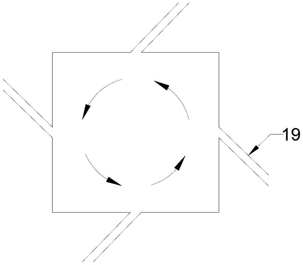
优选地,所述的壳体截面为圆形,所述的壳体外壁面上等距设置至少三个喷吹管。Preferably, the cross section of the casing is circular, and at least three blowing pipes are equidistantly arranged on the outer wall of the casing.
优选地,在水平面内,所述的喷吹管和壳体相接点所在切线与所述喷吹管的夹角为15~45°,压缩空气呈15~45°斜角喷入壳体内部,例如可以是15°、17°、19°、21°、23°、25°、27°、29°、31°、33°、35°、37°、39°、41°、43°或45°,但并不仅限于所列举的数值,该数值范围内其他未列举的数值同样适用。Preferably, in the horizontal plane, the angle between the tangent of the point where the blowing pipe and the casing meet and the blowing pipe is 15-45°, and the compressed air is injected into the casing at an oblique angle of 15-45°, for example, it can be is 15°, 17°, 19°, 21°, 23°, 25°, 27°, 29°, 31°, 33°, 35°, 37°, 39°, 41°, 43° or 45°, but Not limited to the recited values, other non-recited values within the range of values apply equally.
第二方面,本发明提供了一种内部设置有如第一方面所述的吹灰组件的SCR反应装置,所述的SCR反应装置包括立式壳体以及横向设置于立式壳体内部的至少一层催化剂层。In a second aspect, the present invention provides an SCR reaction device provided with the soot blowing assembly as described in the first aspect. The SCR reaction device includes a vertical casing and at least one laterally disposed inside the vertical casing. layer catalyst layer.
所述的立式壳体底部设置有如第一方面所述的吹灰组件。The bottom of the vertical casing is provided with the soot blowing assembly described in the first aspect.
本申请在催化剂层下方设置涡旋式吹灰组件,通过涡旋式吹灰组件在壳体内部产生的涡流气旋,增大了催化剂层底部的空气扰动,有效解决了烟道积灰造成的烟道负载过大和底部管道堵塞问题,保证了SCR反应装置的正常运行。In the present application, a vortex type soot blowing component is arranged under the catalyst layer, and the vortex cyclone generated by the vortex type soot blower component inside the shell increases the air disturbance at the bottom of the catalyst layer, and effectively solves the problem of smoke caused by soot accumulation in the flue. Excessive channel load and blockage of the bottom pipeline ensure the normal operation of the SCR reaction device.
需要说明的是,为了完整实现SCR脱硝工艺,整套SCR脱硝系统除了包括本发明限定的SCR反应装置外,必然还包括还原剂储罐和还原剂喷射装置等通用设备,还原剂喷射装置设置于SCR反应装置的烟气进口管路上,还原剂喷射装置外接还原剂储罐,烟气流经烟气进口管路时与还原剂喷射装置喷入的还原剂接触混合后通入SCR反应装置。但也可以理解的是,以上内容均为本领域技术人员所公知,为现有技术中已公开的SCR脱硝系统中的必要设备,本发明的发明点也不在于此,而在于对SCR脱硝装置内部结构的改进,至于与SCR脱硝装置连接的其余设备,例如上述还原剂喷射装置、还原剂储罐等均不属于本发明的保护范围和公开范围,即便本发明并未对整套SCR脱硝系统的结构进行详细说明,本领域技术人员也能根据所掌握的技术知识还原出整套SCR脱硝系统。It should be noted that, in order to fully realize the SCR denitration process, the entire SCR denitration system, in addition to the SCR reaction device defined in the present invention, must also include general equipment such as a reducing agent storage tank and a reducing agent injection device. The reducing agent injection device is arranged in the SCR. On the flue gas inlet pipeline of the reaction device, the reducing agent injection device is connected to an external reducing agent storage tank. When the flue gas flows through the flue gas inlet pipeline, it contacts and mixes with the reducing agent injected by the reducing agent injection device and then passes into the SCR reaction device. However, it can also be understood that the above contents are known to those skilled in the art, and are necessary equipment in the SCR denitration system disclosed in the prior art. The improvement of the internal structure, as for the remaining equipment connected to the SCR denitration device, such as the above-mentioned reducing agent injection device, reducing agent storage tank, etc., do not belong to the scope of protection and disclosure of the present invention, even if the present invention does not apply to the entire SCR denitration system. The structure is described in detail, and those skilled in the art can also restore the entire SCR denitration system according to the technical knowledge they have mastered.
作为本发明一种优选的技术方案,所述的立式壳体顶部入口设置有水平方向的变径进口烟道,所述的立式壳体底部出口设置有水平方向的变径出口烟道,烟气沿水平方向由进口烟道进入立式壳体由上至下依次穿过所述的催化剂层后沿水平方向由出口烟道排出。As a preferred technical solution of the present invention, the top inlet of the vertical casing is provided with a horizontal variable diameter inlet flue, and the bottom outlet of the vertical casing is provided with a horizontal variable diameter outlet flue, The flue gas enters the vertical casing from the inlet flue along the horizontal direction, passes through the catalyst layer in sequence from top to bottom, and is discharged from the outlet flue along the horizontal direction.
优选地,所述的进口烟道与立式壳体对接的转弯烟道内部设置有至少两组导流板,所述的导流板用于改变进入进口烟道的烟气流向。Preferably, at least two sets of deflectors are arranged inside the turning flue where the inlet flue is connected to the vertical casing, and the deflectors are used to change the flow direction of the flue gas entering the inlet flue.
优选地,所述的导流板为分段结构的弧直型导流板。Preferably, the deflector is an arc-straight deflector with a segmented structure.
优选地,所述的立式壳体顶部设置有至少一层整流格栅。Preferably, at least one layer of rectifying grille is provided on the top of the vertical housing.
优选地,所述的整流格栅等距间隔设置。Preferably, the rectifying grids are arranged at equal intervals.
优选地,相邻两个整流格栅之间的距离控制在40~100mm,例如可以是40mm、50mm、60mm、70mm、80mm、90mm或100mm,但并不仅限于所列举的数值,该数值范围内其他未列举的数值同样适用。Preferably, the distance between two adjacent rectifying grids is controlled within 40-100mm, for example, it can be 40mm, 50mm, 60mm, 70mm, 80mm, 90mm or 100mm, but it is not limited to the listed values, within the range of the values Other non-recited values also apply.
优选地,所述的出口烟道上方的立式壳体外壁面处设置有所述的吹灰组件;Preferably, the soot blowing assembly is provided on the outer wall surface of the vertical casing above the outlet flue;
优选地,所述的出口烟道上设置有颗粒物检测装置,所述的颗粒物检测装置用于对出口烟道排烟中的颗粒物浓度进行检测。Preferably, the outlet flue is provided with a particulate matter detection device, and the particulate matter detection device is used to detect the concentration of particulate matter in the exhaust smoke from the outlet flue.
作为本发明一种优选的技术方案,所述的导流板分为内侧导流板和外侧导流板,所述的内侧导流板设置于进口烟道与立式壳体对接的转弯烟道内侧,所述的外侧导流板设置于进口烟道与立式壳体对接的转弯烟道外侧,所述的内侧导流板和外侧导流板沿烟气流向呈放射状分布。As a preferred technical solution of the present invention, the deflector is divided into an inner deflector and an outer deflector, and the inner deflector is arranged on the turning flue where the inlet flue and the vertical casing are butted On the inner side, the outer deflector is arranged on the outside of the turning flue where the inlet flue and the vertical casing are butted, and the inner deflector and the outer deflector are radially distributed along the flue gas flow direction.
优选地,所述的内侧导流板沿烟气流向包括对接的内侧弧形导流板和内侧直导流板,所述的内侧弧形导流板向转弯烟道内侧延伸形成内侧直导流板。Preferably, the inner side deflector includes a butt-jointed inner arc-shaped deflector and an inner straight deflector along the flue gas flow direction, and the inner arc-shaped deflector extends toward the inside of the turning flue to form an inner straight deflector plate.
优选地,所述的内侧直导流板与竖直方向的夹角为5~15°,例如可以是5°、6°、7°、8°、9°、10°、11°、12°、13°、14°或15°,但并不仅限于所列举的数值,该数值范围内其他未列举的数值同样适用。Preferably, the included angle between the inner straight deflector and the vertical direction is 5° to 15°, such as 5°, 6°, 7°, 8°, 9°, 10°, 11°, 12° , 13°, 14° or 15°, but are not limited to the recited values, and other unrecited values within this range of values are equally applicable.
优选地,所述的外侧导流板沿烟气流向包括对接的外侧弧形导流板和外侧直导流板,所述的外侧弧形导流板沿竖直方向延伸形成外侧直导流板。Preferably, the outer baffle plate includes a butt-jointed outer arc-shaped baffle plate and an outer straight baffle plate along the flue gas flow direction, and the outer arc-shaped baffle plate extends in the vertical direction to form an outer straight baffle plate .
本发明在进口烟道外侧为若干弧型导流板与竖直向下的直导流板相接,内侧为若干弧型导流板与角度为5~15°的直导流板相接,通过特殊结构的导流板有效提升了烟气进入进口烟道的分布均匀性和速度均匀性。In the present invention, on the outside of the inlet flue, a plurality of arc-shaped guide plates are connected with the vertical downward straight guide plates, and on the inner side, a plurality of arc-shaped guide plates are connected with the straight guide plates with an angle of 5-15°, The distribution uniformity and speed uniformity of the flue gas entering the inlet flue are effectively improved through the special structure of the deflector.
需要说明的是,本发明对内侧导流板和外侧导流板的数量不作具体要求和特殊限定,本领域技术人员可根据进口烟道截面积和待处理烟气量进行适当调整,但需要至少设置一个内侧导流板和一个外侧导流板,通过内侧导流板和外侧导流板的放射状分布,使得二者之间形成的烟道截面积沿烟气流向逐渐增大,从而提升了烟气的分布均匀性。It should be noted that the present invention does not impose specific requirements or special restrictions on the number of inner and outer baffles. Those skilled in the art can make appropriate adjustments according to the cross-sectional area of the inlet flue and the amount of flue gas to be treated, but at least Set up an inner deflector and an outer deflector, and through the radial distribution of the inner deflector and the outer deflector, the cross-sectional area of the flue formed between the two gradually increases along the flue gas flow direction, thereby improving the smoke flow. uniformity of gas distribution.
作为本发明一种优选的技术方案,每个催化剂层上方均设置有吹灰装置,所述的吹灰装置用于对催化剂层喷吹清灰。As a preferred technical solution of the present invention, a soot blowing device is provided above each catalyst layer, and the soot blowing device is used to spray and clean the catalyst layer.
优选地,所述的吹灰装置的压缩空气入口合并为一路后通过压缩空气主管接入压缩空气源,压缩空气源经压缩空气主管分别向不同的吹灰装置提供压缩空气。Preferably, the compressed air inlets of the soot blowing device are combined into one channel and then connected to the compressed air source through the compressed air main pipe, and the compressed air source respectively provides compressed air to different soot blowing devices through the compressed air main pipe.
优选地,所述的压缩空气主管上设置有加热装置,压缩空气源提供的压缩空气经加热装置加热后分配至不同的吹灰装置。Preferably, a heating device is provided on the compressed air main pipe, and the compressed air provided by the compressed air source is heated by the heating device and distributed to different soot blowing devices.
优选地,所述的吹灰装置和所述的喷吹管分别使用不同的压缩空气源或共用同一个压缩空气源,进一步优选地,所述的吹灰装置和所述的喷吹管共用同一个压缩空气源。Preferably, the soot blowing device and the blowing pipe use different compressed air sources respectively or share the same compressed air source, further preferably, the soot blowing device and the blowing pipe share the same compressed air source air source.
优选地,所述的压缩空气主管上外设压缩空气支管,所述的压缩空气支管的出口端接入所述的喷吹管,压缩空气源提供的压缩空气经加热装置加热后通入喷吹管对立式壳体底部易积灰区域进行喷吹清灰。Preferably, a compressed air branch pipe is arranged on the main compressed air main pipe, the outlet end of the compressed air branch pipe is connected to the blowing pipe, and the compressed air provided by the compressed air source is heated by the heating device and then flows into the blowing pipe pair. The dust accumulation area at the bottom of the vertical shell is sprayed to clean the dust.
优选地,所述的压缩空气支管上设置有调节阀。Preferably, the compressed air branch pipe is provided with a regulating valve.
本发明在吹灰装置和涡旋吹灰组件的压缩空气流向前端设置加热装置,压缩空气经预热后通入吹灰装置和涡旋吹灰组件以减少烟气和压缩空气之间的温差。In the present invention, a heating device is arranged at the front end of the compressed air flow of the soot blowing device and the vortex soot blowing assembly, and the compressed air is preheated and passed into the soot blowing device and the vortex soot blowing assembly to reduce the temperature difference between the flue gas and the compressed air.
作为本发明一种优选的技术方案,所述的催化剂层采用的催化剂包括载体以及负载于载体上的活性成分和辅助成分。As a preferred technical solution of the present invention, the catalyst used in the catalyst layer includes a carrier and active components and auxiliary components supported on the carrier.
优选地,所述的载体包括TiO2、分子筛、介孔氧化铝或蒙脱石中的一种或至少两种的组合。Preferably, the carrier comprises one or a combination of at least two of TiO 2 , molecular sieve, mesoporous alumina or montmorillonite.
优选地,所述的活性成分包括V2O5。Preferably, the active ingredient includes V 2 O 5 .
优选地,所述的辅助成分包括WO3。Preferably, the auxiliary component includes WO 3 .
作为本发明一种优选的技术方案,所述的立式壳体内部沿烟气流向间隔设置有第一催化剂层、第二催化剂层和第三催化剂层。As a preferred technical solution of the present invention, a first catalyst layer, a second catalyst layer and a third catalyst layer are arranged in the vertical casing at intervals along the flue gas flow direction.
第三方面,本发明提供了一种采用如第二方面所述的SCR反应装置对烟气进行脱硝的方法,所述的方法包括:In a third aspect, the present invention provides a method for denitrifying flue gas using the SCR reaction device described in the second aspect, the method comprising:
烟气进入SCR反应装置内,由下至上依次穿过催化剂层,在催化剂的作用下与还原剂发生选择性催化氧化反应脱除烟气中的NOx,通过吹灰组件定期对立式壳体内部易积灰区域进行喷吹清灰。The flue gas enters the SCR reaction device, passes through the catalyst layer from bottom to top, and undergoes a selective catalytic oxidation reaction with the reducing agent under the action of the catalyst to remove NO x in the flue gas. The internal dust accumulation area is sprayed to clean the dust.
作为本发明一种优选的技术方案,所述的方法具体包括如下步骤:As a preferred technical solution of the present invention, the method specifically comprises the following steps:
(Ⅰ)烟气进入SCR反应装置内,由下至上依次穿过催化剂层,在催化剂的作用下与还原剂发生选择性催化氧化反应脱除烟气中的NOx;(I) The flue gas enters the SCR reaction device, passes through the catalyst layer from bottom to top, and undergoes a selective catalytic oxidation reaction with the reducing agent under the action of the catalyst to remove NO x in the flue gas;
(Ⅱ)压缩空气源提供的压缩空气经加热装置预热后分配进入不同的吹灰装置,定期对催化剂层进行喷吹清灰;(II) The compressed air provided by the compressed air source is preheated by the heating device and distributed to different soot blowing devices, and the catalyst layer is regularly sprayed to clean the soot;
(Ⅲ)压缩空气源提供的压缩空气经加热装置预热后通入喷吹管,压缩空气喷入立式壳体后形成水平面上的气流涡旋实现了对立式壳体底部易积灰区域的喷吹清灰。(III) The compressed air provided by the compressed air source is preheated by the heating device and then passed into the blowing pipe. After the compressed air is sprayed into the vertical casing, an airflow vortex on the horizontal plane is formed, which realizes the protection of the dust-prone area at the bottom of the vertical casing. Blow out dust.
优选地,步骤(Ⅱ)中,所述的吹灰装置对催化剂层的吹灰频率为一天1~3次,例如可以是一天1次、一天2次或一天3次,但并不仅限于所列举的数值,该数值范围内其他未列举的数值同样适用。Preferably, in step (II), the soot blowing frequency of the soot blowing device on the catalyst layer is 1 to 3 times a day, for example, it can be once a day, twice a day or three times a day, but it is not limited to the listed value, other non-recited values within this value range also apply.
优选地,当出口烟道内排出的烟气中颗粒物的浓度大于20mg/Nm3时,开启调节阀,进行步骤(Ⅲ)。Preferably, when the concentration of particulate matter in the flue gas discharged from the outlet flue is greater than 20 mg/Nm 3 , the regulating valve is opened, and step (III) is performed.
示例性地,采用本发明提供的SCR反应装置对水泥窑窑尾烟气进行SCR脱硝处理,所述的处理过程具体包括如下步骤:Exemplarily, the SCR reaction device provided by the present invention is used to perform SCR denitrification treatment on the flue gas of the cement kiln tail, and the treatment process specifically includes the following steps:
(1)SCR反应装置在运行初期,水泥窑窑尾烟道排出的烟气由SCR脱硝装置的进口烟道流入,经过导流板提高了烟气的分布均匀性,再穿过整流格栅,提高了烟气的速度均匀性,烟气中的氮氧化物和还原剂(氨气)在催化剂层上反应生成氮气和水,烟气得以净化,烟气依次穿过第一催化剂层、第二催化剂层和第三催化剂层后由出口烟道排出,颗粒物检测装置对出口烟道排烟中的颗粒物浓度进行检测,检测到出口颗粒物浓度小于20mg/Nm3,表明此时SCR反应装置的内壁和底部积灰较少,关闭调节阀,吹灰组件停止工作,减少压缩空气和加热装置的使用,降低运行成本。运行一段时间后,烟气中的颗粒物堵塞催化剂层,压缩空气源提供的压缩空气经加热装置预热后通入吹灰装置,对下方相对的催化剂层喷吹清灰,减少催化剂层积灰堵塞,通过预热减少压缩空气与烟气之间的温差,吹灰装置对催化剂层的吹灰频率为一天1~3次。(1) In the early stage of operation of the SCR reaction device, the flue gas discharged from the kiln tail flue of the cement kiln flows into the inlet flue of the SCR denitrification device, passes through the guide plate to improve the uniformity of the distribution of the flue gas, and then passes through the rectification grille. The speed uniformity of the flue gas is improved, and the nitrogen oxides and the reducing agent (ammonia) in the flue gas react on the catalyst layer to generate nitrogen and water, and the flue gas is purified. After the catalyst layer and the third catalyst layer are discharged from the outlet flue, the particulate matter detection device detects the concentration of particulate matter in the exhaust flue gas from the outlet flue. Less soot deposits at the bottom, close the regulating valve, stop the soot blowing components, reduce the use of compressed air and heating devices, and reduce operating costs. After running for a period of time, the particulate matter in the flue gas blocks the catalyst layer. The compressed air provided by the compressed air source is preheated by the heating device and then passes into the soot blowing device, and blows the opposite catalyst layer below to remove dust to reduce the clogging of the catalyst layer. , reduce the temperature difference between the compressed air and the flue gas by preheating, and the soot blowing frequency of the soot blowing device on the catalyst layer is 1 to 3 times a day.
(2)在后期运行过程中,颗粒物检测装置检测到出口烟道排烟中的出口颗粒物浓度大于20mg/Nm3,表明此时的SCR反应装置的内壁和底部积灰严重,此时开启调节阀,调节阀开度调节到一半大小,压缩空气源提供的压缩空气经加热装置预热后送入涡旋式吹灰组件,预热后的压缩空气经喷吹管以30°倾斜喷入立式壳体底部积灰区域,压缩空气在立式壳体底部形成水平面上的涡旋气流,实现对底部积灰的清扫。(2) During the later operation, the particulate matter detection device detected that the outlet particulate matter concentration in the exhaust flue gas was greater than 20mg/Nm 3 , indicating that the inner wall and bottom of the SCR reaction device had serious dust accumulation at this time, and the regulating valve was opened at this time. , the opening of the regulating valve is adjusted to half the size, the compressed air provided by the compressed air source is preheated by the heating device and sent to the scroll soot blowing component, and the preheated compressed air is injected into the vertical shell at a 30° inclination through the injection pipe In the ash accumulation area at the bottom of the body, the compressed air forms a vortex air flow on the horizontal plane at the bottom of the vertical casing to realize the cleaning of the ash accumulation at the bottom.
与现有技术相比,本发明的有益效果为:Compared with the prior art, the beneficial effects of the present invention are:
(1)本发明提供的涡旋式吹灰组件通过压缩空气源提供压缩空气,该压缩空气经喷吹管以某一角度倾斜吹入壳体,在壳体易积灰区域形成有序的涡旋气流,实现对积灰的喷吹清扫。(1) The scroll type soot blowing assembly provided by the present invention provides compressed air through a compressed air source, and the compressed air is blown into the casing at a certain angle through the injection pipe, and an orderly vortex is formed in the area where the casing is prone to fouling. Air flow to achieve blowing and cleaning of dust deposits.
(2)本发明在进口烟道外侧为若干弧型导流板与竖直向下的直导流板相接,内侧为若干弧型导流板与角度为5~15°的直导流板相接,通过特殊结构的导流板有效提升了烟气进入进口烟道的分布均匀性和速度均匀性。(2) In the present invention, on the outside of the inlet flue, several arc-shaped baffles are connected to the vertical downward straight baffles, and on the inner side are several arc-shaped baffles and the straight baffles with an angle of 5 to 15° Connected to each other, the distribution uniformity and speed uniformity of the flue gas entering the inlet flue are effectively improved through the special structure of the deflector.
(3)本申请在催化剂层下方设置涡旋式吹灰组件,通过涡旋式吹灰组件在壳体内部产生的涡流气旋,增大了催化剂层底部的空气扰动,有效解决了烟道积灰造成的烟道负载过大和底部管道堵塞问题。(3) In the present application, a vortex type soot blowing assembly is arranged below the catalyst layer, and the vortex cyclone generated by the vortex type soot blower assembly inside the casing increases the air disturbance at the bottom of the catalyst layer, effectively solving the problem of soot accumulation in the flue The resulting flue load is too large and the bottom pipe is blocked.
(4)本发明在吹灰装置和涡旋吹灰组件的压缩空气流向前端设置加热装置,压缩空气经预热后通入吹灰装置和涡旋吹灰组件以减少烟气和压缩空气之间的温差。(4) In the present invention, a heating device is arranged at the front end of the compressed air flow of the soot blowing device and the vortex soot blowing assembly, and the compressed air is preheated and passed into the soot blowing device and the vortex soot blowing assembly to reduce the gap between the flue gas and the compressed air. temperature difference.
附图说明Description of drawings
图1为本发明一个具体实施方式提供的用于多边形截面壳体的涡旋式吹灰组件的结构示意图;1 is a schematic structural diagram of a scroll-type sootblower assembly for a polygonal section shell provided by a specific embodiment of the present invention;
图2为本发明一个具体实施方式提供的用于圆形截面壳体的涡旋式吹灰组件的结构示意图;2 is a schematic structural diagram of a scroll-type sootblower assembly for a casing with a circular section provided by a specific embodiment of the present invention;
图3为本发明一个具体实施方式提供的SCR反应装置的结构示意图。FIG. 3 is a schematic structural diagram of an SCR reaction device provided by a specific embodiment of the present invention.
其中,1-立式壳体;2-进口烟道;3-出口烟道;4-第一催化剂层;5-第二催化剂层;6-第三催化剂层;7-第一吹灰装置;8-第二吹灰装置;9-第三吹灰装置;10-压缩空气主管;11-加热装置;12-压缩空气源;13-压缩空气支管;14-调节阀;15-吹灰组件;16-外侧导流板;17-内侧导流板;18-颗粒物检测装置;19-喷吹管。Wherein, 1-vertical shell; 2-inlet flue; 3-outlet flue; 4-first catalyst layer; 5-second catalyst layer; 6-third catalyst layer; 7-first soot blowing device; 8-Second soot blowing device; 9-Third soot blowing device; 10-Compressed air main pipe; 11-Heating device; 12-Compressed air source; 13-Compressed air branch pipe; 14-Regulating valve; 16-outer deflector; 17-inner deflector; 18-particulate detection device; 19-spray pipe.
具体实施方式Detailed ways
需要理解的是,在本发明的描述中,术语“中心”、“纵向”、“横向”、“上”、“下”、“前”、“后”、“左”、“右”、“竖直”、“水平”、“顶”、“底”、“内”、“外”等指示的方位或位置关系为基于附图所示的方位或位置关系,仅是为了便于描述本发明和简化描述,而不是指示或暗示所指的装置或元件必须具有特定的方位、以特定的方位构造和操作,因此不能理解为对本发明的限制。此外,术语“第一”、“第二”等仅用于描述目的,而不能理解为指示或暗示相对重要性或者隐含指明所指示的技术特征的数量。由此,限定有“第一”、“第二”等的特征可以明示或者隐含地包括一个或者更多个该特征。在本发明的描述中,除非另有说明,“多个”的含义是两个或两个以上。It should be understood that in the description of the present invention, the terms "center", "portrait", "horizontal", "top", "bottom", "front", "rear", "left", "right", " The orientation or positional relationship indicated by vertical, horizontal, top, bottom, inner, outer, etc. is based on the orientation or positional relationship shown in the drawings, and is only for the convenience of describing the present invention and The description is simplified rather than indicating or implying that the device or element referred to must have a particular orientation, be constructed and operate in a particular orientation, and therefore should not be construed as limiting the invention. In addition, the terms "first", "second", etc. are used for descriptive purposes only, and should not be construed as indicating or implying relative importance or implying the number of indicated technical features. Thus, a feature defined as "first", "second", etc., may expressly or implicitly include one or more of that feature. In the description of the present invention, unless otherwise specified, "plurality" means two or more.
需要说明的是,在本发明的描述中,除非另有明确的规定和限定,术语“设置”、“相连”、“连接”应做广义理解,例如,可以是固定连接,也可以是可拆卸连接,或一体连接;可以是机械连接,也可以是电连接;可以是直接相连,也可以通过中间媒介间接相连,可以是两个元件内部的连通。对于本领域的普通技术人员而言,可以通过具体情况理解上述术语在本发明中的具体含义。It should be noted that, in the description of the present invention, unless otherwise expressly specified and limited, the terms "arranged", "connected" and "connected" should be understood in a broad sense, for example, it may be a fixed connection or a detachable connection Connection, or integral connection; it can be mechanical connection or electrical connection; it can be directly connected, or indirectly connected through an intermediate medium, and it can be internal communication between two components. For those of ordinary skill in the art, the specific meanings of the above terms in the present invention can be understood through specific situations.
下面结合附图并通过具体实施方式来进一步说明本发明的技术方案。The technical solutions of the present invention are further described below with reference to the accompanying drawings and through specific embodiments.
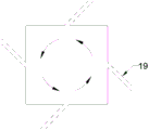
在一个具体实施方式中,本发明提供了一种涡旋式吹灰组件15,所述的涡旋式吹灰组件15如图1或图2所示,包括沿壳体周向设置的至少三个喷吹管19,喷吹管19沿壳体外周的同一向倾斜设置于壳体外壁面上,喷吹管19外接压缩空气源12,压缩空气经喷吹管19喷入壳体内部形成气流涡旋对壳体内部易积灰区域进行喷吹清灰。In a specific embodiment, the present invention provides a vortex
喷吹管19沿壳体周向水平设置,喷吹管19在水平面上沿同一倾斜方向设置于壳体外壁面上,压缩空气经喷吹管19喷入壳体内部形成水平面上的气流涡旋。The blowing
本发明提供的吹灰组件15具有较强的适配性,对壳体截面形状的要求较低,现今市面上存在的任意形状壳体均适用于本发明提供的涡旋式吹灰组件15。一种可能适用的壳体截面形状为:如图1所示,当壳体横截面为正方形时,壳体的每侧外壁面上分别设置有至少一个喷吹管19,在水平面内,喷吹管19与壳体外壁面的夹角为15~45°,压缩空气呈15~45°斜角喷入壳体内部。如图2所示,当壳体截面为圆形时,壳体外壁面上等距设置至少三个喷吹管19,在水平面内,喷吹管19和壳体相接点所在切线与所述喷吹管19的夹角为15~45°,压缩空气呈15~45°斜角喷入壳体内部。The
在另一个具体实施方式中,本发明提供了一种内部设置有上述吹灰组件15的SCR反应装置,所述的SCR反应装置如图3所示,包括立式壳体1以及横向设置于立式壳体1内部的至少一层催化剂层,如图3所示,立式壳体1内部沿烟气流向间隔设置有第一催化剂层4、第二催化剂层5和第三催化剂层6,立式壳体1底部设置有上述吹灰组件15。In another specific embodiment, the present invention provides an SCR reaction device provided with the above-mentioned
立式壳体1顶部入口设置有水平方向的变径进口烟道2,立式壳体1底部出口设置有水平方向的变径出口烟道3,烟气沿水平方向由进口烟道2进入立式壳体1由上至下依次穿过催化剂层后沿水平方向由出口烟道3排出。The top inlet of the vertical housing 1 is provided with a horizontal variable
进口烟道2与立式壳体1对接的转弯烟道内部设置有至少两组导流板,导流板用于改变进入进口烟道2的烟气流向。导流板为分段结构的弧直型导流板。立式壳体1顶部设置有至少一层整流格栅,整流格栅等距间隔设置,相邻两个整流格栅之间的距离控制在40~100mm。出口烟道3上方的立式壳体1外壁面处设置有上述吹灰组件15,出口烟道3上设置有颗粒物检测装置18。At least two sets of deflectors are arranged inside the turning flue where the
导流板分为内侧导流板17和外侧导流板16,内侧导流板17设置于进口烟道2与立式壳体1对接的转弯烟道内侧,外侧导流板16设置于进口烟道2与立式壳体1对接的转弯烟道外侧,内侧导流板17和外侧导流板16沿烟气流向呈放射状分布。内侧导流板17沿烟气流向包括对接的内侧弧形导流板和内侧直导流板,内侧弧形导流板向转弯烟道内侧延伸形成内侧直导流板,内侧直导流板与竖直方向的夹角为5~15°。外侧导流板16沿烟气流向包括对接的外侧弧形导流板和外侧直导流板,外侧弧形导流板沿竖直方向延伸形成外侧直导流板。The deflector is divided into an
每个催化剂层上方均设置有吹灰装置,吹灰装置用于对催化剂层喷吹清灰。具体地,如图3所示,第一催化剂层4上方设置第一吹灰装置7,第二催化剂层5上方设置第二吹灰装置8,第三催化剂层6上方设置第三吹灰装置9,各层吹灰装置的压缩空气入口合并为一路后通过压缩空气主管10接入压缩空气源12,压缩空气源12经压缩空气主管10分别向不同的吹灰装置提供压缩空气。压缩空气主管10上设置有加热装置11,压缩空气源12提供的压缩空气经加热装置11加热后分配至不同的吹灰装置。A soot blowing device is arranged above each catalyst layer, and the soot blowing device is used to spray and clean the catalyst layer. Specifically, as shown in FIG. 3 , a
吹灰装置和所述的喷吹管19共用同一个压缩空气源12,压缩空气主管10上外设压缩空气支管13,压缩空气支管13的出口端接入所述的喷吹管19,压缩空气源12提供的压缩空气经加热装置11加热后通入喷吹管19对立式壳体1底部易积灰区域进行喷吹清灰,压缩空气支管13上设置有调节阀14。The soot blowing device and the blowing
催化剂层采用的催化剂包括载体以及负载于载体上的活性成分和辅助成分,载体可选为TiO2、分子筛、介孔氧化铝或蒙脱石中的一种或至少两种的组合,活性成分包括V2O5,辅助成分包括WO3。The catalyst used in the catalyst layer includes a carrier and active components and auxiliary components supported on the carrier. The carrier can be selected from one or a combination of at least two of TiO 2 , molecular sieve, mesoporous alumina or montmorillonite. The active components include V 2 O 5 and auxiliary components include WO 3 .
在另一个具体实施方式中,本发明提供了一种采用上述SCR反应装置对烟气进行脱硝处理,所述的处理过程具体包括如下步骤:In another specific embodiment, the present invention provides a denitrification treatment of flue gas using the above-mentioned SCR reaction device, and the treatment process specifically includes the following steps:
(Ⅰ)烟气进入SCR反应装置内,由下至上依次穿过催化剂层,在催化剂的作用下与还原剂发生选择性催化氧化反应脱除烟气中的NOx;(I) The flue gas enters the SCR reaction device, passes through the catalyst layer from bottom to top, and undergoes a selective catalytic oxidation reaction with the reducing agent under the action of the catalyst to remove NO x in the flue gas;
(Ⅱ)压缩空气源12提供的压缩空气经加热装置11预热后分配进入不同的吹灰装置,定期对催化剂层进行喷吹清灰,吹灰装置对催化剂层的吹灰频率为一天1~3次;(II) The compressed air provided by the
(Ⅲ)当出口烟道3内排出的烟气中颗粒物的浓度大于20mg/Nm3时,开启调节阀14,压缩空气源12提供的压缩空气经加热装置11预热后通入喷吹管19,压缩空气喷入立式壳体1后形成水平面上的气流涡旋实现了对立式壳体1底部易积灰区域的喷吹清灰。(III) When the concentration of particulate matter in the flue gas discharged from the outlet flue 3 is greater than 20 mg/Nm 3 , the regulating
实施例1Example 1
本实施例提供了一种SCR反应装置,所述的SCR反应装置如图3所示,包括立式壳体1以及横向设置于立式壳体1内部的三层催化剂层,具体地,沿烟气流向间隔设置有第一催化剂层4、第二催化剂层5和第三催化剂层6。三层催化剂层采用的催化剂包括载体以及负载于载体上的活性成分和辅助成分,载体为TiO2,活性成分为V2O5,辅助成分为WO3。This embodiment provides an SCR reaction device. As shown in FIG. 3 , the SCR reaction device includes a vertical casing 1 and three catalyst layers laterally arranged inside the vertical casing 1 . A first catalyst layer 4 , a second catalyst layer 5 and a
立式壳体1顶部入口设置有水平方向的变径进口烟道2,立式壳体1底部出口设置有水平方向的变径出口烟道3,烟气沿水平方向由进口烟道2进入立式壳体1由上至下依次穿过第一催化剂层4、第二催化剂层5和第三催化剂层6后沿水平方向由出口烟道3排出。The top inlet of the vertical housing 1 is provided with a horizontal variable
进口烟道2与立式壳体1对接的转弯烟道内部设置有五组分段结构的弧直型导流板,五组弧直型导流板按照结构不同分为2组内侧导流板17和3组外侧导流板16,2组内侧导流板17平行设置于进口烟道2与立式壳体1对接的转弯烟道内侧,3组外侧导流板16平行设置于进口烟道2与立式壳体1对接的转弯烟道外侧,内侧导流板17和外侧导流板16沿烟气流向呈放射状分布。内侧导流板17沿烟气流向包括对接的内侧弧形导流板和内侧直导流板,内侧弧形导流板向转弯烟道内侧延伸形成内侧直导流板,内侧直导流板与竖直方向的夹角为5°。外侧导流板16沿烟气流向包括对接的外侧弧形导流板和外侧直导流板,外侧弧形导流板沿竖直方向延伸形成外侧直导流板。Inside the turning flue where the
立式壳体1顶部设置有四层整流格栅,整流格栅等距间隔设置,相邻两个整流格栅之间的距离控制在40mm。The top of the vertical housing 1 is provided with four layers of rectifying grids, the rectifying grids are arranged at equal intervals, and the distance between two adjacent rectifying grids is controlled at 40mm.
立式壳体1底部的外壁面处设置有涡旋式吹灰组件15,所述的涡旋式吹灰组件15如图1所示,包括沿立式壳体1周向设置的四个喷吹管19,喷吹管19在水平面上沿同一倾斜方向设置于立式壳体1的外壁面上,喷吹管19外接压缩空气源12,压缩空气经喷吹管19喷入立式壳体1内部从而形成水平面上的气流涡旋(如图1所示的喷吹管19倾斜方向,立式壳体1内部形成逆时针的气流涡旋),对立式壳体1底部易积灰区域进行喷吹清灰,喷吹管19与立式壳体1外壁面的夹角为15°。出口烟道3上设置有颗粒物检测装置18。The outer wall surface of the bottom of the vertical casing 1 is provided with a vortex type
第一催化剂层4上方设置第一吹灰装置7,第二催化剂层5上方设置第二吹灰装置8,第三催化剂层6上方设置第三吹灰装置9,吹灰装置用于对相应的催化剂层喷吹清灰。各层吹灰装置的压缩空气入口合并为一路后通过压缩空气主管10接入压缩空气源12,压缩空气源12经压缩空气主管10分别向不同的吹灰装置提供压缩空气。压缩空气主管10上还设置有加热装置11,压缩空气源12提供的压缩空气经加热装置11加热后分配至不同的吹灰装置。吹灰装置和喷吹管19共用同一个压缩空气源12,三者之间的连接关系为:压缩空气主管10上外设压缩空气支管13,压缩空气支管13的出口端接入喷吹管19,压缩空气源12提供的压缩空气经加热装置11加热后通入喷吹管19对立式壳体1底部易积灰区域进行喷吹清灰,压缩空气支管13上设置有调节阀14。A first
实施例2Example 2
本实施例与实施例1在结构参数上的区别在于:The difference between this embodiment and Embodiment 1 in terms of structural parameters is:
(1)三层催化剂层采用的催化剂包括载体以及负载于载体上的活性成分和辅助成分,载体为分子筛,活性成分为V2O5,辅助成分为WO3。(1) The catalyst used in the three-layer catalyst layer includes a carrier, active components and auxiliary components supported on the carrier, the carrier is molecular sieve, the active component is V 2 O 5 , and the auxiliary component is WO 3 .
(2)进口烟道2与立式壳体1对接的转弯烟道内部设置有四组分段结构的弧直型导流板,四组弧直型导流板按照结构不同分为2组内侧导流板17和2组外侧导流板16;(2) Four groups of arc-straight deflectors with segmented structure are arranged inside the turning flue where the
(3)内侧直导流板与竖直方向的夹角为7°;(3) The angle between the inner straight deflector and the vertical direction is 7°;
(4)立式壳体1顶部设置有四层整流格栅,相邻两个整流格栅之间的距离控制在60mm;(4) A four-layer rectifying grid is arranged on the top of the vertical housing 1, and the distance between two adjacent rectifying grids is controlled at 60mm;
(5)喷吹管19与立式壳体1外壁面的夹角为20°;(5) The angle between the blowing
其余结构特征与实施例1完全相同,不再赘述。The remaining structural features are exactly the same as those in Embodiment 1, and will not be repeated here.
实施例3Example 3
本实施例与实施例1在结构参数上的区别在于:The difference between this embodiment and Embodiment 1 in terms of structural parameters is:
(1)三层催化剂层采用的催化剂包括载体以及负载于载体上的活性成分和辅助成分,载体为介孔氧化铝,活性成分为V2O5,辅助成分为WO3;(1) The catalyst used in the three-layer catalyst layer includes a carrier, active components and auxiliary components supported on the carrier, the carrier is mesoporous alumina, the active component is V 2 O 5 , and the auxiliary component is WO 3 ;
(2)进口烟道2与立式壳体1对接的转弯烟道内部设置有五组分段结构的弧直型导流板,五组弧直型导流板按照结构不同分为3组内侧导流板17和2组外侧导流板16;(2) Five groups of arc-straight deflectors with segmented structure are arranged inside the turning flue where the
(3)内侧直导流板与竖直方向的夹角为10°;(3) The angle between the inner straight deflector and the vertical direction is 10°;
(4)立式壳体1顶部设置有两层整流格栅,相邻两个整流格栅之间的距离控制在70mm;(4) Two layers of rectifying grids are arranged on the top of the vertical housing 1, and the distance between two adjacent rectifying grids is controlled at 70mm;
(5)喷吹管19与立式壳体1外壁面的夹角为30°。(5) The angle between the blowing
其余结构特征与实施例1完全相同,不再赘述。The remaining structural features are exactly the same as those in Embodiment 1, and will not be repeated here.
实施例4Example 4
本实施例与实施例1在结构参数上的区别在于:The difference between this embodiment and Embodiment 1 in terms of structural parameters is:
(1)三层催化剂层采用的催化剂包括载体以及负载于载体上的活性成分和辅助成分,载体为蒙脱石,活性成分为V2O5,辅助成分为WO3;(1) The catalyst used in the three-layer catalyst layer includes a carrier, active components and auxiliary components supported on the carrier, the carrier is montmorillonite, the active component is V 2 O 5 , and the auxiliary component is WO 3 ;
(2)进口烟道2与立式壳体1对接的转弯烟道内部设置有六组分段结构的弧直型导流板,六组弧直型导流板按照结构不同分为3组内侧导流板17和3组外侧导流板16;(2) The curved flue where the
(3)内侧直导流板与竖直方向的夹角为12°;(3) The angle between the inner straight deflector and the vertical direction is 12°;
(4)立式壳体1顶部设置有两层整流格栅,整流格栅等距间隔设置,相邻两个整流格栅之间的距离控制在80mm;(4) Two layers of rectifying grids are arranged on the top of the vertical housing 1, the rectifying grids are arranged at equal intervals, and the distance between two adjacent rectifying grids is controlled at 80mm;
(5)喷吹管19与立式壳体1外壁面的夹角为40°。(5) The angle between the blowing
其余结构特征与实施例1完全相同,不再赘述。The remaining structural features are exactly the same as those in Embodiment 1, and will not be repeated here.
实施例5Example 5
本实施例与实施例1的区别在于:The difference between this embodiment and Embodiment 1 is:
(1)进口烟道2与立式壳体1对接的转弯烟道内部设置有三组分段结构的弧直型导流板,三组弧直型导流板按照结构不同分为1组内侧导流板17和2组外侧导流板16;(1) The curved flue where the
(2)内侧直导流板与竖直方向的夹角为15°;(2) The angle between the inner straight deflector and the vertical direction is 15°;
(3)立式壳体1顶部设置有两层整流格栅,两层整流格栅之间的距离控制在100mm;(3) Two layers of rectifying grids are arranged on the top of the vertical housing 1, and the distance between the two layers of rectifying grids is controlled at 100mm;
(4)喷吹管19与立式壳体1外壁面的夹角为45°。(4) The angle between the blowing
其余结构特征与实施例1完全相同,不再赘述。The remaining structural features are exactly the same as those in Embodiment 1, and will not be repeated here.
应用实施例Application Example
采用实施例1提供的SCR反应装置对水泥窑窑尾烟气进行SCR脱硝处理,所述的处理过程具体包括如下步骤:The SCR reaction device provided in Example 1 is used to carry out SCR denitration treatment on the kiln tail gas of the cement kiln, and the treatment process specifically includes the following steps:
(1)SCR反应装置在运行初期,水泥窑窑尾烟道排出的烟气由SCR脱硝装置的进口烟道2流入,经过导流板提高了烟气的分布均匀性,再穿过整流格栅,提高了烟气的速度均匀性,烟气中的氮氧化物和还原剂(氨气)在催化剂层上反应生成氮气和水,烟气得以净化,烟气依次穿过第一催化剂层4、第二催化剂层5和第三催化剂层6后由出口烟道3排出,颗粒物检测装置18对出口烟道3排烟中的颗粒物浓度进行检测,检测到出口颗粒物浓度小于20mg/Nm3,表明此时SCR反应装置的内壁和底部积灰较少,关闭调节阀14,吹灰组件15停止工作,减少压缩空气和加热装置11的使用,降低运行成本。运行一段时间后,烟气中的颗粒物堵塞催化剂层,压缩空气源12提供的压缩空气经加热装置11预热后通入吹灰装置,对下方相对的催化剂层喷吹清灰,减少催化剂层积灰堵塞,通过预热减少压缩空气与烟气之间的温差;吹灰装置对催化剂层的吹灰频率为一天1~3次。(1) In the early stage of operation of the SCR reaction device, the flue gas discharged from the kiln tail flue of the cement kiln flows into the
(2)在后期运行过程中,颗粒物检测装置18检测到出口烟道3排烟中的出口颗粒物浓度大于20mg/Nm3,表明此时的SCR反应装置的内壁和底部积灰严重,此时开启调节阀14,调节阀14开度调节到一半大小,压缩空气源12提供的压缩空气经加热装置11预热后送入涡旋式吹灰组件15,预热后的压缩空气经喷吹管19以30°倾斜喷入立式壳体1底部积灰区域,压缩空气在立式壳体1底部形成水平面上的涡旋气流,实现对底部积灰的清扫。(2) In the later operation process, the particulate
申请人声明,以上所述仅为本发明的具体实施方式,但本发明的保护范围并不局限于此,所属技术领域的技术人员应该明了,任何属于本技术领域的技术人员在本发明揭露的技术范围内,可轻易想到的变化或替换,均落在本发明的保护范围和公开范围之内。The applicant declares that the above are only specific embodiments of the present invention, but the protection scope of the present invention is not limited thereto. Those skilled in the art should Changes or substitutions that can be easily conceived within the technical scope all fall within the protection scope and disclosure scope of the present invention.
Claims (10)
Priority Applications (1)
| Application Number | Priority Date | Filing Date | Title |
|---|---|---|---|
| CN202010407842.4A CN111545053A (en) | 2020-05-14 | 2020-05-14 | Vortex type soot blowing assembly, SCR reaction device comprising same and method |
Applications Claiming Priority (1)
| Application Number | Priority Date | Filing Date | Title |
|---|---|---|---|
| CN202010407842.4A CN111545053A (en) | 2020-05-14 | 2020-05-14 | Vortex type soot blowing assembly, SCR reaction device comprising same and method |
Publications (1)
| Publication Number | Publication Date |
|---|---|
| CN111545053A true CN111545053A (en) | 2020-08-18 |
Family
ID=71998540
Family Applications (1)
| Application Number | Title | Priority Date | Filing Date |
|---|---|---|---|
| CN202010407842.4A Pending CN111545053A (en) | 2020-05-14 | 2020-05-14 | Vortex type soot blowing assembly, SCR reaction device comprising same and method |
Country Status (1)
| Country | Link |
|---|---|
| CN (1) | CN111545053A (en) |
Cited By (1)
| Publication number | Priority date | Publication date | Assignee | Title |
|---|---|---|---|---|
| CN115228862A (en) * | 2022-08-04 | 2022-10-25 | 长鑫存储技术有限公司 | Transfer chamber and cleaning method thereof, semiconductor processing equipment |
Citations (3)
| Publication number | Priority date | Publication date | Assignee | Title |
|---|---|---|---|---|
| CN104407563A (en) * | 2014-12-05 | 2015-03-11 | 盐城工学院 | Automatic control device for soot blower in SCR denitration process, and control method of control device |
| CN204508110U (en) * | 2015-03-31 | 2015-07-29 | 马鞍山市天工科技有限公司 | Cyclone type thermal powerplant coal bunker block clearing equipment |
| CN205235765U (en) * | 2015-12-14 | 2016-05-18 | 江苏科行环境工程技术有限公司 | Be applied to high cloud of dust gas SCR denitrification facility of cement kiln |
-
2020
- 2020-05-14 CN CN202010407842.4A patent/CN111545053A/en active Pending
Patent Citations (3)
| Publication number | Priority date | Publication date | Assignee | Title |
|---|---|---|---|---|
| CN104407563A (en) * | 2014-12-05 | 2015-03-11 | 盐城工学院 | Automatic control device for soot blower in SCR denitration process, and control method of control device |
| CN204508110U (en) * | 2015-03-31 | 2015-07-29 | 马鞍山市天工科技有限公司 | Cyclone type thermal powerplant coal bunker block clearing equipment |
| CN205235765U (en) * | 2015-12-14 | 2016-05-18 | 江苏科行环境工程技术有限公司 | Be applied to high cloud of dust gas SCR denitrification facility of cement kiln |
Cited By (2)
| Publication number | Priority date | Publication date | Assignee | Title |
|---|---|---|---|---|
| CN115228862A (en) * | 2022-08-04 | 2022-10-25 | 长鑫存储技术有限公司 | Transfer chamber and cleaning method thereof, semiconductor processing equipment |
| CN115228862B (en) * | 2022-08-04 | 2023-10-17 | 长鑫存储技术有限公司 | Transmission chamber, cleaning method thereof and semiconductor processing equipment |
Similar Documents
| Publication | Publication Date | Title |
|---|---|---|
| CN102614779B (en) | Dedusting-denitrating integrated device | |
| CN108970396A (en) | A kind of high temperature fume dust removal denitrification integrated device and its technique | |
| CN207076339U (en) | Integral type selective catalytic reduction denitration device | |
| CN202893166U (en) | Flue gas denitration device | |
| CN111545053A (en) | Vortex type soot blowing assembly, SCR reaction device comprising same and method | |
| CN113522012B (en) | Flue gas denitration ammonia spraying mixing system, static mixer thereof and ammonia spraying control method | |
| CN202933624U (en) | Ash removing device in SCR (selective catalytic reduction) flue gas de-nitrification system | |
| CN112138542A (en) | High-temperature flue gas dedusting, denitration and desulfurization system and method | |
| CN208612147U (en) | A kind of cement industry dedusting denitration device | |
| CN105289302A (en) | Rotary-cut SCR denitration method and apparatus thereof | |
| CN212091625U (en) | A dry ultra-clean emission device for lime kiln flue gas | |
| CN219186307U (en) | A New Spray Scrubber | |
| CN111229031A (en) | A dust removal system and a dust removal method therefor | |
| CN219149758U (en) | An integrated collaborative purification device for exhaust gas containing particulate matter and nitrogen oxides | |
| CN208612146U (en) | A kind of dedusting denitration device | |
| CN116899325A (en) | Short-flow metal filter bag dust remover and flue gas dust removal method | |
| CN118341285A (en) | Large temperature difference gas mixing, purification and rectification device | |
| CN206184257U (en) | A flue gas vortex device for SCR deNOx systems | |
| CN105457397A (en) | Pre-dedusting device for low-temperature SCR system in cement kiln | |
| CN209378791U (en) | The gas-particle two-phase current equalizer of selective catalytic reduction denitration device | |
| CN116624878A (en) | System and process for treating exhaust emission of ammonia-containing silane | |
| CN109985522A (en) | SCR flue gas denitration reactor and method embedded in waste heat boiler for cement furnace flue gas denitration | |
| CN214382645U (en) | A flue gas denitrification device | |
| CN211988013U (en) | SCR denitration system | |
| CN204619751U (en) | A kind of SCR denitration device being applied to cement clinker production line kiln tail high-dust flue gas |
Legal Events
| Date | Code | Title | Description |
|---|---|---|---|
| PB01 | Publication | ||
| PB01 | Publication | ||
| SE01 | Entry into force of request for substantive examination | ||
| SE01 | Entry into force of request for substantive examination | ||
| RJ01 | Rejection of invention patent application after publication | ||
| RJ01 | Rejection of invention patent application after publication |
Application publication date: 20200818 |