CN113168004A - Calibration of mobile electronic devices connected to user-wearable headsets - Google Patents
Calibration of mobile electronic devices connected to user-wearable headsets Download PDFInfo
- Publication number
- CN113168004A CN113168004A CN201880099633.9A CN201880099633A CN113168004A CN 113168004 A CN113168004 A CN 113168004A CN 201880099633 A CN201880099633 A CN 201880099633A CN 113168004 A CN113168004 A CN 113168004A
- Authority
- CN
- China
- Prior art keywords
- camera
- mobile electronic
- headset
- electronic device
- display device
- Prior art date
- Legal status (The legal status is an assumption and is not a legal conclusion. Google has not performed a legal analysis and makes no representation as to the accuracy of the status listed.)
- Granted
Links
Images


Classifications
-
- G—PHYSICS
- G06—COMPUTING OR CALCULATING; COUNTING
- G06T—IMAGE DATA PROCESSING OR GENERATION, IN GENERAL
- G06T7/00—Image analysis
- G06T7/80—Analysis of captured images to determine intrinsic or extrinsic camera parameters, i.e. camera calibration
- G06T7/85—Stereo camera calibration
-
- G—PHYSICS
- G02—OPTICS
- G02B—OPTICAL ELEMENTS, SYSTEMS OR APPARATUS
- G02B27/00—Optical systems or apparatus not provided for by any of the groups G02B1/00 - G02B26/00, G02B30/00
- G02B27/0025—Optical systems or apparatus not provided for by any of the groups G02B1/00 - G02B26/00, G02B30/00 for optical correction, e.g. distorsion, aberration
-
- G—PHYSICS
- G02—OPTICS
- G02B—OPTICAL ELEMENTS, SYSTEMS OR APPARATUS
- G02B27/00—Optical systems or apparatus not provided for by any of the groups G02B1/00 - G02B26/00, G02B30/00
- G02B27/0093—Optical systems or apparatus not provided for by any of the groups G02B1/00 - G02B26/00, G02B30/00 with means for monitoring data relating to the user, e.g. head-tracking, eye-tracking
-
- G—PHYSICS
- G02—OPTICS
- G02B—OPTICAL ELEMENTS, SYSTEMS OR APPARATUS
- G02B27/00—Optical systems or apparatus not provided for by any of the groups G02B1/00 - G02B26/00, G02B30/00
- G02B27/01—Head-up displays
- G02B27/017—Head mounted
-
- G—PHYSICS
- G06—COMPUTING OR CALCULATING; COUNTING
- G06T—IMAGE DATA PROCESSING OR GENERATION, IN GENERAL
- G06T7/00—Image analysis
- G06T7/70—Determining position or orientation of objects or cameras
-
- G—PHYSICS
- G02—OPTICS
- G02B—OPTICAL ELEMENTS, SYSTEMS OR APPARATUS
- G02B27/00—Optical systems or apparatus not provided for by any of the groups G02B1/00 - G02B26/00, G02B30/00
- G02B27/01—Head-up displays
- G02B27/0101—Head-up displays characterised by optical features
- G02B2027/0138—Head-up displays characterised by optical features comprising image capture systems, e.g. camera
-
- G—PHYSICS
- G06—COMPUTING OR CALCULATING; COUNTING
- G06T—IMAGE DATA PROCESSING OR GENERATION, IN GENERAL
- G06T2207/00—Indexing scheme for image analysis or image enhancement
- G06T2207/30—Subject of image; Context of image processing
- G06T2207/30244—Camera pose
Landscapes
- Physics & Mathematics (AREA)
- General Physics & Mathematics (AREA)
- Engineering & Computer Science (AREA)
- Optics & Photonics (AREA)
- Computer Vision & Pattern Recognition (AREA)
- Theoretical Computer Science (AREA)
- User Interface Of Digital Computer (AREA)
- Position Input By Displaying (AREA)
- Studio Devices (AREA)
- Image Analysis (AREA)
Abstract
A mobile electronic device (120) is provided for use with a headset (100). A camera (122) outputs a digital picture of a portion of the headset. The display device displays information for viewing by a user wearing the headset (100). The processor retrieves calibration parameters characterizing at least a pose of the camera relative to the display device and processes the digital pictures from the camera to identify a pose of the optically identifiable feature within the digital pictures. A pose of the mobile electronic device (120) relative to the holder is identified based on the identified pose of the optically identifiable feature within the digital picture and based at least on the pose of the camera relative to the display device as characterized by the calibration parameters. The processor controls where the graphical object is rendered on the display device based on the recognized pose of the mobile electronic device (120) relative to the holder.
Description
Technical Field
The present disclosure relates to head mounted displays that use mobile electronic devices to display information for viewing by a wearer.
Background
Head Mounted Displays (HMDs) will become an increasing part of the future device ecosystem of society for interpersonal communication, gaming and other applications. Mixed Reality (MR) headsets are a type of HMD that augments the content seen by a user in the real world through computer-generated information (e.g., graphical objects, text, markup, etc.) in a way that can make the information appear to the user as if it existed in the real world. MR headsets may enable a user to interact in a seemingly realistic or physical manner using special electronic devices, such as haptic devices that track the user's motion and may provide haptic feedback to the user.
MR headsets based on smart phones or other mobile electronic devices are becoming more and more popular, and several pioneering companies introduced new devices in 2017 and 2018, called Mira Prism, Holokit, Ghost AR and leovo Mirage AR, respectively. These headsets are relatively inexpensive and may be used with apple, samsung, google, and other smart phones. For example, developers for Ghost and holkit devices may perform object recognition and 6 degrees of freedom (DOF) localization using MR Software Development Kit (SDK) tools of google and apple, referred to as arche and ARKit, respectively. The Ghost device can also be used in Virtual Reality (VR) by changing the front lens from perspective to non-perspective. In the entire VR field, google Cardboard, google Daydream, and samsung Gear VRs are smartphone-based VR headsets that are also low in price and highly well known.
MR headsets can be generally characterized as two types: non-lens headsets (e.g., Mira Prism type headsets and holkit and Ghost headsets depicted in fig. 1 and 2) and lens-based headsets. For a mirrorless headset, light emitted by a display device of the mobile electronic device 120 (e.g., a smartphone) is projected onto the lens 110 (e.g., along the path 200 a). The lens 110 is at least partially transparent (i.e., see-through) to allow ambient light to pass through for viewing by a user wearing the MR headset, while also being configured to reflect at least a portion of the light emitted by the display device back for viewing by the user. The lens 110 may or may not have a light converging or light dispersing effect (e.g., magnifying light from a real-world feature). In fig. 1 and 2, lens 110 reflects light toward the user's eye (e.g., along path 200b, primarily by specular reflection) and toward camera 122 of device 120 (e.g., along path 200c, by diffusion). In contrast, for mirror-based headsets, light emitted by the display device of the mobile electronic device 120 is projected onto a mirror that reflects the light toward a reflective see-through lens for reflection, which may be directly or indirectly toward the user's eyes.
Some mirror-based headsets configure the rear camera of the mobile electronic device 120 to have a field of view of the world, which is beneficial because the rear camera can be configured to provide better quality video than the front camera. For example, the current version of the ARCore or ARKit SDK can only operate efficiently with a rear camera because of its higher imaging quality relative to a front camera. Some mirror-based headsets enable more flexible positioning of the mobile electronic device than non-mirror headsets due to limitations in the relative positioning between the see-through lens of the headset and the display device of the mobile electronic device.
MR systems can operate by having the display device of the mobile electronic device project information and other virtual content toward the headset lens (mirror-less design) or headset mirror (mirror-based design). Digital pictures (e.g., video frames) from a camera are processed to identify real-world features (e.g., tracking markers or other real-world objects) that can be used for localization (e.g., correlating real-world and virtual-world (i.e., MR headset reference) coordinate systems), feature identification, and/or streaming video to a remote viewer (e.g., for learning/teaching MR applications, enabling a remote expert to view video captured by a technician's MR headset and provide responsive guidance).
One of the main drawbacks of these low cost headsets is that the quality of the three dimensional (3D) virtual content rendered by the headset is significantly lower (e.g., distortion, blur, contrast, location in the real world) when the mobile electronic device is not optimally positioned (e.g., position and angular orientation) relative to the headset. Referring to fig. 1, a mobile electronic device may display two images that allow a user to perceive a 3D image in a headphone lens. If the two displayed images are not properly aligned with the lens, the user will see a distorted image. Furthermore, if the position of the virtual content to be displayed is defined according to the real world position inferred by the mobile electronic device camera (e.g. the device tracks the markers and the virtual content will be enhanced over the markers of one of the most common AR applications), or if the mobile electronic device is not correctly placed in the headset, the transition between the camera and the headset lens (where the virtual content appears) will change. This will negatively impact the user experience as the virtual content will no longer align with the real world content.
Furthermore, if the calibration algorithm is performed when the mobile electronic device has a particular pose, the calibration will no longer be valid if the user subsequently replaces the mobile electronic device with a different pose than when the calibration was performed earlier. Furthermore, if the mobile electronic device slides relative to the headset during use, the relative pose between the mobile electronic device and the headset will change.
The reason that the mobile electronic device may be sub-optimally placed in the headset is that the mobile electronic device has many different sizes (length, width and thickness) which complicates how the headset should be configured to releasably hold a changing mobile electronic device. Thus, considerable variability can lead to how the same user positions the mobile electronic device and how different users position their mobile electronic device relative to the headset. To avoid performance degradation due to this variability, the samsung Gear VR headset is only suitable for samsung brand devices (samsung makes a device specific holder attachment for samsung brand devices), which limits how the samsung device is placed relative to the headset.
Disclosure of Invention
Some embodiments disclosed herein are directed to a mobile electronic device for a headset that includes a holder configured to releasably hold the mobile electronic device in a defined pose relative to the headset. The mobile electronic device includes a camera, a display device, a processor, and a memory. The camera is configured to output a digital picture and is arranged by the holder to view a portion of the headset. The display device is arranged by the holder to display information for viewing by a user wearing the headset. The processor is operatively connected to the camera and the display device. The memory stores program code that is executed by the processor to perform operations. The operations include retrieving from memory calibration parameters characterizing at least a pose of the camera with respect to the display device. The operations process a digital picture from a camera to identify a pose of an optically identifiable feature within the digital picture, the digital picture captured while the mobile electronic device is held by a holder. The operation identifies a pose of the mobile electronic device relative to the holder based on the identified pose of the optically identifiable feature within the digital picture and based at least on a pose of the camera relative to the display device as characterized by the calibration parameters. The operation controls where the graphical object is rendered on the display device based on the recognized pose of the mobile electronic device relative to the holder.
These and other embodiments may provide the potential advantage that the mobile electronic device may optimize its operation to compensate for how the device is determined to be positioned relative to the headset. Thus, for example, when the mobile electronic device is placed in a headset and the display device is laterally offset from a preferred location, the mobile electronic device may determine such an offset and adjust its operation to more optimally display information for viewing by a user wearing the headset. Alternatively or additionally, the mobile electronic device may provide guidance to the user on how the pose of the mobile electronic device should be adjusted.
Some other embodiments disclosed herein are directed to corresponding methods of operation performed by a processor of a mobile electronic device. As described above, the mobile electronic device includes a camera and a display device for use with a headset having a holder configured to releasably hold the mobile electronic device in a defined pose relative to the headset. The method includes retrieving calibration parameters characterizing at least a pose of the camera relative to the display device. The method processes a digital picture from a camera to identify a pose of an optically identifiable feature within the digital picture, the digital picture captured while the mobile electronic device is held by a holder. The method identifies a pose of the mobile electronic device relative to the holder based on the identified pose of the optically identifiable feature within the digital picture and based at least on a pose of the camera relative to the display device as characterized by the calibration parameters. The method controls where the graphical object is rendered on the display device based on the recognized pose of the mobile electronic device relative to the holder.
Other mobile electronic devices and corresponding methods according to embodiments will be or become apparent to one with skill in the art upon review of the following drawings and detailed description. All such additional mobile electronic devices and methods are intended to be included within this description and protected by the accompanying claims.
Drawings
The various aspects of the disclosure are illustrated by way of example and not limitation in the figures. In the drawings:
fig. 1 illustrates an MR system including an MR headset holding a mobile electronic device configured to operate in accordance with some embodiments of the present disclosure;
FIG. 2 shows a side view of the MR system of FIG. 1;
FIG. 3 illustrates another embodiment of a VR system having a mobile electronic device with a display device that projects an image to a user and partially reflects the image to a camera in accordance with some embodiments of the present disclosure;
fig. 4-9 are flowcharts of operations that may be performed by a mobile electronic device, according to some embodiments of the present disclosure;
fig. 10 is a block diagram of components of a mobile electronic device configured to operate in accordance with some other embodiments of the present disclosure;
fig. 11a shows a back view of a headset holding a mobile electronic device having a front camera (FCam) and a back camera (BCam) and a side cross-sectional view of the headset;
FIG. 11b illustrates a top cross-sectional view and a front cross-sectional view of a headset holding a display device of a mobile electronic device in an optimal position relative to the headset;
fig. 11c shows a top cross-sectional view and a front cross-sectional view of a headset holding the mobile electronic device in an offset (incremental) position relative to a sub-optimal lateral movement of the headset; and
fig. 12 shows various views of a virtual image plane in which a user perceives that a display device of a mobile electronic device is positioned when the user wears a headset.
Detailed Description
The present inventive concept will be described more fully hereinafter with reference to the accompanying drawings, in which examples of embodiments of the inventive concept are shown. The inventive concept may, however, be embodied in many different forms and should not be construed as limited to the embodiments set forth herein. Rather, these embodiments are provided so that this disclosure will be thorough and complete, and will fully convey the scope of the various inventive concepts to those skilled in the art. It should also be noted that these embodiments are not mutually exclusive. Components from one embodiment may be assumed by default to be present/used in another embodiment.
Fig. 1 shows an MR system comprising an MR headset 100, the MR headset 100 holding a mobile electronic device 120 configured to operate according to some embodiments of the present disclosure. Referring to fig. 1, the MR headset 100 includes a lens 110 through which a user wearing the MR headset can view real world features, and the MR headset 100 further includes a holder 121 configured to releasably hold the mobile electronic device 120 in a defined orientation relative to the lens 110.
The mobile electronic device 120 includes a camera 122, a display device (1040 in fig. 10), and a processor (1006 in fig. 10). The camera 122 is configured to output digital pictures (e.g., still pictures and/or video) and is arranged by the holder 121 to view at least a portion of the lens 110 of the MR headset 100. The display device 1040 is arranged to display information that is projected on the lens 110 for direct or indirect reflection towards the user's eye (i.e. when wearing the MR headset 100) and the camera 122 of the mobile electronic device 120. Although not shown, the headset may include an intermediate mirror between the lens 110 and the user's eye and/or the camera 122, and thus the light may be reflected directly or indirectly toward the user's eye and/or the camera 122.
The mobile electronic device 120 may include, but is not limited to, a smart phone, a palmtop computer, a tablet computer, a gaming device, or other computing device. For the sake of brevity, "mobile electronic devices" are also referred to herein as "mobile devices" and "devices". As will be explained in further detail below, various operations described below as being performed by the mobile electronic device 120 may additionally, or alternatively, be performed by another electronic device communicatively connected to the mobile electronic device 120.
Fig. 2 shows a side view of the MR system of fig. 1. Referring to fig. 2, display device 1040 (fig. 10) of mobile electronic device 120 displays information that is projected onto lens 110 along path 200a for reflection back along path 200b toward the user's eye and along path 200c toward camera 122.
Fig. 3 illustrates another configuration of VR headset 300 that may be used in accordance with some embodiments. Referring to fig. 3, the display device 1040 (fig. 10) of the mobile electronic device 120 displays information projected toward the lens (the user views the display device 1040 through the lens). Images from the display device 1040 may also be reflected back to the camera 122 by the lens and/or the user's eye (fig. 10).
One approach that has been implemented by google Daydream VR to attempt to determine the pose of the mobile electronic device 120 relative to the MR headset is to use two conductive pads 310 (fig. 3) that are configured to make contact with the display device 1040 (fig. 10). The mobile electronic device 120 may then measure the position of the pad 310 based on the location where the pad 310 contacts the touch-sensitive display device, and thereby determine the location of the mobile electronic device 120 relative to the headset 300. Further, the mobile electronic device 120 may measure the roll orientation relative to the headset 300. However, the mobile electronic device 120 will not be able to measure displacement in other orientations. This approach also requires that the pad be built into the headset 300, making it more complex and expensive to manufacture, while requiring the smartphone to detect contacts in the display device while running the MR application. Further, the requirement that the pad 310 contact the display device reduces the display area in which content may be displayed for viewing by the user.
Embodiments of the present disclosure aim to calibrate the pose of a mobile electronic device relative to a headset so that virtual content can be rendered to allow better viewing by a user wearing the headset. The results of one or more earlier calibration operations may be used to facilitate and improve the current calibration operation.
As used herein, the term "gesture" refers to a position and/or rotation angle of one device (e.g., a mobile electronic device) relative to another device (e.g., a headset) or relative to a defined coordinate system. Thus, the pose may be defined based on only the multi-dimensional position of one device relative to the other device or relative to a defined coordinate system, only the multi-dimensional rotation angle of the device relative to the other device or relative to a defined coordinate system, or a combination of the multi-dimensional position and the multi-dimensional rotation angle. Thus, the term "attitude" is used to refer to a position, a rotation angle, or a combination thereof.
Fig. 4 is a flow diagram of operations and methods that may be performed by a mobile electronic device to determine its pose with respect to a headset. The headset includes a holder configured to releasably hold the mobile electronic device in a defined pose relative to the headset. The mobile electronic device includes a camera (e.g., 122 in fig. 10), a display device (e.g., 1040 in fig. 10), a processor (e.g., 1006 in fig. 10) operatively connected to the camera and the display device, and a memory (e.g., 1010 in fig. 10) storing program code (e.g., 1012 in fig. 10) executed by the processor to perform operations.
Referring to fig. 4, the operation retrieves 400 from memory calibration parameters that characterize at least the pose of the camera relative to the display device. A digital picture from a camera is processed 402 to identify a pose of an optically identifiable feature within the digital picture, the digital picture captured while a mobile electronic device is held by a holder. A pose of the mobile electronic device is recognized 404 relative to the holder based on the recognized pose of the optically recognizable feature within the digital picture and based at least on the pose of the camera relative to the display device as characterized by the calibration parameters. The operation controls 406 where the graphical object is rendered on the display device based on the recognized pose of the mobile electronic device relative to the holder.
Thus, the mobile electronic device uses the camera to determine the pose of the device relative to the headset, and then uses the relative pose to improve how the graphical object is rendered on the display device for viewing by the user wearing the headset.
Condition triggering calibration of mobile electronic device pose in headset
The operation of calibrating the relative pose of the mobile electronic device with respect to the headset may be triggered by receiving a notification that the mobile electronic device has been inserted into the holder of the headset. The operations may responsively capture an image using a front-facing camera of the mobile electronic device, retrieve stored calibration parameters for the mobile electronic device and the headset, and determine new calibration parameters based on the captured image and the retrieved calibration parameters. In some embodiments, the calibration operation is performed in response to the calibration notification being triggered.
In one embodiment, a calibration notification is triggered when a new MR or VR application begins executing on the mobile electronic device, where the application is configured for use with a headset. In another embodiment, a calibration notification is triggered when a user initiates a recalibration operation by, for example, selecting a user selectable flag provided by an application.
In yet another embodiment, the MR or VR application is launched to display an image or text that prompts the user to insert the mobile electronic device into the MR or VR headset. Subsequent successful insertion is detected by activating the front-facing camera and repeating the check to determine when the interior of the headset is captured. For example, digital pictures from the front-facing camera may be processed to identify the pose of optically identifiable features of the headset, such as pads 310, lenses, eye openings, and/or other structural features or markings on the headset 300 in fig. 3 or the headset 100 in fig. 1 and 2.
In another embodiment, corneal imaging techniques are used to detect reflections of the displayed virtual content on the cornea of the user's eye. A calibration notification will be triggered when the image quality (distortion, position in the real world, etc.) no longer meets the defined quality rules, which may be at least partly specified by the user.
In another embodiment, digital pictures from a camera may be processed to track the position at which the user's eyes are pointing. The calibration notification may be triggered based on determining that the user's eye pointing is off center from the desired location, or pointing in another manner that satisfies the defined rules for triggering calibration.
Recognizing gestures of optically recognizable features using a front-facing camera
In some embodiments, the optically identifiable characteristic relates to a characteristic of the headset and/or the eyes of the user wearing the headset. A digital picture from a front-facing camera of the mobile electronic device 120, which is captured while the mobile electronic device is held by the holder, may be processed 402 as part of the operations of fig. 4 to identify a pose of an optically identifiable feature within the digital picture. Digital pictures captured by a front-facing camera may be processed to identify the pose of the user's eyes relative to the camera.
For example, processing (402 in fig. 4) a digital picture from a camera to identify a pose of an optically identifiable feature within the digital picture captured while the mobile electronic device is held by the holder may include: the digital picture is processed to identify a pose of an optically recognizable feature of the headset captured by the camera.
The operations may also include determining a pose of an optically identifiable feature of the headset within a previous digital picture captured by the camera during a previous calibration process based on the calibration parameters retrieved (400 in fig. 4) from the memory. During the current calibration process, an operation is performed that processes (402 in fig. 4) the digital picture from the camera to identify a pose of an optically recognizable feature of the headset within the digital picture. The operation of identifying (404 in fig. 4) the pose of the mobile electronic device relative to the holder may be based on a comparison of the identified pose of the optically identifiable feature of the headset within a digital picture captured during a current calibration procedure with the pose of the optically identifiable feature of the headset within a previous digital picture captured during a previous calibration procedure.
In some other embodiments, the optically identifiable feature identified by the mobile electronic device is a feature of a calibration pattern that is projected (e.g., flashed) by the display device onto the headset and/or the user's eye and thereby reflected to be captured by the camera. The optically recognizable features of the calibration pattern are processed as part of an operation of determining a pose of the mobile electronic device relative to the headset.
For example, the operations may further include: the calibration pattern is displayed on the display device to cause the camera to capture a portion of the calibration pattern within the digital picture by reflecting a portion of the calibration pattern from a surface of the headset and/or from an eye of the user. Processing (402 of fig. 4) a digital picture from a camera to recognize a pose of an optically recognizable feature within the digital picture includes: the digital picture is processed to identify a pose of a defined feature within a portion of the calibration pattern.
Retrieving stored calibration parameters for smart phones and headsets
As described above, the calibration parameters retrieved from the memory of the mobile electronic device at least characterize the pose of the camera relative to the display device. The calibration parameters may characterize other previously determined or defined relationships (relationship position, pose, etc.) between the mobile electronic device, the front camera, the back camera, the display device, the headset, a holder of the headset, a lens of the headset, and/or a viewing port of the headset. Alternatively or additionally, the calibration parameters may characterize the operation of the camera, display device, or other components of the mobile electronic device and/or headset. For example, the calibration parameters may include any one or more of:
1) optically identifiable features and their positions and/or sets of optically identifiable features and their relative poses based on digital pictures captured from a front-facing camera while using the mobile electronic device during a previous calibration process;
2) a digital picture image captured from a front-facing camera during a previous calibration process;
3) distortion parameters (e.g., barrel distortion) corresponding to the camera and/or lens of the headset, which may be determined and/or defined during a previous calibration process;
4) a headset parameter characterizing a relationship between headset and eye coordinates determined during a previous calibration procedure; and
5) off-axis projection parameters characterizing projections between eye coordinates and display coordinates of one or both of the user's eyes determined during a previous calibration procedure.
In one embodiment, the prior calibration process may be performed as an off-line or factory calibration process. In another embodiment, the previous calibration process may be performed as a one-time calibration process performed on a per user basis and may correspond to operations for a Single Point Active Alignment Method (SPAAM), such as disclosed by M Tuceryan and n.navab, for optical see-through HMD calibration of AR, page 149-158 in IEEE 2000.
In some other illustrative embodiments, the operations performed by the mobile electronic device may include: distortion parameters of the camera that affect the pose of the defined feature within the digital picture are determined from the calibration parameters retrieved from the memory. Processing the digital picture from the camera to identify the pose of the optically identifiable feature within the digital picture may compensate for distortion parameters of the camera.
The mobile electronic device may perform the following operations: determining a headset-to-eye parameter from the calibration parameters retrieved from the memory, the headset-to-eye parameter identifying, in at least two dimensions, a distance between at least one location on the headset determined during a previous calibration procedure and at least one eye of the user. The operation of controlling where to render the graphical object on the display device may then be further performed based on the headset-to-eye parameters.
The mobile electronic device may perform the following operations: off-axis projection parameters are determined from the calibration parameters retrieved from the memory, which parameters identify in at least two-dimensional space a distance between at least one location on the display device determined during a previous calibration procedure operation and at least one eye of the user, and then control of where to render the graphical object on the display device may be further performed based on the off-axis projection parameters.
Determining new calibration parameters based on captured digital pictures and previously stored calibration parameters
Further operations that may be performed by the mobile electronic device are now described in the context of the embodiments of fig. 11a, 11b and 11 c. Fig. 11a shows a back view of a headset holding a mobile electronic device with a front camera (FCam) and a back camera (BCam) and a side cross-sectional view of the headset. Fig. 11b shows a top and front cross-sectional view of a headset holding a display device of a mobile electronic device in an optimal position relative to the headset. Fig. 11c shows a top and front cross-sectional view of a headset holding the mobile electronic device in an offset (incremental) position relative to a sub-optimal lateral displacement of the headset. As will be explained in further detail below with respect to fig. 11c, the field of view (FOV) of the front camera through which the generated image is displayed on the display device may be adjusted (e.g., laterally shifted) such that the viewport for the left eye becomes smaller and the viewport for the right eye becomes larger.
In the context of fig. 11a to 11c, a headset refers to a fixed part of a headset. Term EleftAnd ErightRefer to the position and orientation (e.g., pose) of the left and right virtual eyes, respectively, that are optimally aligned with the eyes of the real user. BCam is the pose of the rear camera, which may be related only to an optical see-through head mounted display (OST-HMD). FCam is the pose of the front-facing camera, and "display" refers to the physical location of the display device center of the mobile electronic device. Fig. 11a to 11c show an example FOV of a front camera, where it can be seen that for many headsets and mobile electronic devices one of the eye openings will be located inside the FOV of the front camera. The front camera may observe images output by the display device and reflected back to the front camera by a reflective surface of the headset and/or the user's eyes. Thus, the digital picture from the front camera may comprise an image of the display device and/or optically recognizable features of the headset and/or the eyes of the user.
Based on whether the positioning of the eye is feasible, there are two options to adjust the viewport and the projection matrix. The two options may be applied separately as they are for different error sources, or may be applied together to eliminate both errors.
various example operations are described below for option 1 for determining a pose of a mobile electronic device relative to a holder of a headset based on an optical recognition characteristic of the headset. Using the digital picture from the front-facing camera, the mobile electronic device may identify (extract) one or more optically recognizable features of the headset and thereby determine that the mobile electronic device is relative to the headsetPosture of the headset. Examples of such optically identifiable features in the headset may include, but are not limited to, a nose opening, an eye opening, an inner surface corner, and/or printed indicia on the surface of the headset. Using the defined/determined intrinsic camera parameters of the front-facing camera and the dimensions of the headset (which may be retrieved from memory as calibration parameters), the mobile electronic device is operable to derive a camera to headset transformation Which correlates the pose of the camera with the optically recognizable features of the headset within the digital picture. Calibration parameters characterizing the transformation of the camera to the display may be retrieved from memory
 It relates the pose of the camera to the pose of the display device, which may assume that a fixed headset pose is fixed at an intermediate position between the two eye openings. Based on camera to headphone transformation and camera to display transformation (e.g. based on
 Which may correlate the offset between the center of the display and the center of the headset) to generate a transformation of the display to the headset
 Since the size of the display device may be known (defined by calibration parameters in memory), this transformation may be used to adjust for the shift between the viewport for the left and right eye to account for the incrementally shifted positions of the mobile electronic device shown in fig. 11b and 11 c.
In addition to this adjustment, the mobile electronic device may also take into account non-linear distortions caused by the optical system between the screen and the user's eye, such as the case depicted in fig. 12. Fig. 12 shows various views of a virtual image plane in which a user perceives that a display device of a mobile electronic device is positioned when the user wears a headset. Referring to fig. 12, the virtual display plane is positioned at a distance d with respect to the eye. The projection of this configuration is described by the off-axis projection matrix as follows:

in an off-axis projection matrix, the term, refers to the angle of the edge of the virtual display plane at a distance d with respect to the projection center. Thus, the parameters,, d describe the size and position of the image plane relative to the eye. The substitution and minimum parameterization of the projection matrix are defined by fu,fv,r0,c0It is given. In view of this minimal parameterization from the calibration process, the smartphones can be adjusted to changing viewport size and position due to their displacement. The distance d can be set to an arbitrary value and given a relative change in the distance, an adjusted projection matrix can be calculated. Note that the projection matrix for the left eye remains fixed, while the projection matrix for the right eye remains fixed.
Various corresponding operations that may be performed by a mobile electronic device are illustrated in the flow chart of fig. 5. Referring to fig. 5, identifying a pose of the mobile electronic device relative to the holder based on the identified pose of the optically identifiable feature within the digital picture and based at least on the pose of the camera relative to the display device as characterized by the calibration parameters may include: a camera to headset transformation is generated 500 that associates the pose of the camera with an optically recognizable feature of the headset within the digital picture. A camera to display transformation is obtained 502 that associates a pose of the camera with a pose of the display device. Based on the camera to headphone transform and the camera to display transform, a display to headphone transform is generated 504. The following operations may be performed based on the transform displayed to the headset: controlling 506 where to render the graphical object on the display device based on the recognized pose of the mobile electronic device with respect to the holder.
Another operation that may be performed by a mobile electronic device includes: distortion parameters of the camera affecting the pose of the optically identifiable feature of the headset within the digital picture are determined from the calibration parameters retrieved from the memory. An operation of generating a camera to headphone transform may be performed to compensate for distortion parameters of the camera.
The operation of obtaining a camera to display transformation that associates the pose of the camera with the pose of the display device may include: the digital picture from the camera or another digital picture is processed to identify a distance between the camera and the display device relative to the at least two-dimensional coordinate system from a reflected image generated by the image from the display device being reflected by the reflective surface of the headset to the camera. The mobile electronic device may then generate a camera to display transformation based on the distance between the camera and the display device.
Generating a camera to display transformation based on a distance between the camera and the display device may include: data is obtained that characterizes a distance between the holder and a reflective surface of the headset that generates the reflected image. The mobile electronic device may then generate a camera to display transformation based on scaling the distance between the camera and the display device identified in the reflected image based on the data characterizing the distance between the holder and the reflective surface of the headset.
Option 2 for recognizing the pose of the mobile electronic device with respect to the holder:
various exemplary operations are described below for option 2 for determining a pose of a mobile electronic device relative to a holder of a headset based on a recognized pose of a user's eye.
The mobile electronic device may perform further operations to adjust for changes in the user's eye pose relative to the headset, such as shown in fig. 12, which may be due to changed headset positions and/or different users wearing the headset. A feature of the virtual image plane is that its projection can be correct independently of the real eye position (i.e. in case of eye movement, the real world will show the same movement as the virtual image plane). Due to the virtual eye position E and the actual eye position The difference between, all content in front of or behind the plane will show errors. When the front-facing camera of the headset can capture the eye position, the mobile electronic device can process the digital picture to calculate a position matrix
 And
And both of which are described below. Matrix array
 Characterize how the virtual camera is positioned relative to the front camera and will typically be set up in an initial calibration phase. Matrix array
 The position of the actual eye of the user relative to the front camera is characterized, which may now be different from during initial calibration due to the different position of the other using the headset or headphones. The position may be determined by finding a fixed position of the eye (i.e., the corner of the eye) and setting the depth to a fixed value. Alternative techniques, which may include corneal imaging, may also be used to infer eye position (including depth) using a front-facing camera. To adjust the virtual eye position and adjust the projection matrix, the following equation can be used, which characterizes the shift in eye position in the headset coordinate system:

this shift should be applied to both the position of the virtual camera and the projection matrix so that the projection of the virtual image plane remains unchanged, similar to the relationship shown in fig. 12. For example, when Indicating that the eye position has moved downwardsAt 5mm of movement, the virtual eye position will also move 5mm downward. Furthermore, the projection matrix P is adjusted by increasing t by 5mm and decreasing b by 5mmoff. Other parameters will remain unchanged.
Various corresponding operations that may be performed by a mobile electronic device are illustrated in the flow chart of fig. 6. Referring to fig. 6, operations may include processing 600 a digital picture from a camera or another digital picture to identify a pose of a user's eyes and generating 602 a camera-to-eye transformation that associates the pose of the camera with the identified pose of the user's eyes. Operations to control 406 (fig. 4) where the graphical objects are rendered on the display device may then be further performed based on the camera-to-eye transformation.
In one embodiment, when the mobile electronic device detects that it is positioned in the headset in a position and orientation that does not achieve the desired image quality, a message may be displayed to the user indicating that the mobile electronic device should be repositioned by the user. The displacement/rotation to be applied to the mobile electronic device may be calculated in this step based on the previous embodiments and indicated to the user by a notification (e.g. a message indicating a suggested left/right/up/down/left, right rotation, etc. movement until a better placement of the device is achieved).
In another embodiment, the mobile electronic device may inform the user how the mobile electronic device should be moved to obtain improved operation of the headset. Figure 7 is a flowchart of operations that may be performed by a mobile electronic device, according to one embodiment. Referring to fig. 7, the operations may include: in response to the recognized gesture of the mobile electronic device with respect to the holder exceeding the offset threshold, by determining 700 a direction and distance that the mobile electronic device will move with respect to the holder to cause the display device to be within a threshold distance of a defined position on the holder, and then displaying 702 a message on the display device indicating the direction and distance that the mobile electronic device is to move.
In another embodiment, the mobile electronic device may provide dynamic notification updates as the user moves the mobile electronic device seeking to obtain a better pose that will provide improved operation. For example, the mobile electronic device may respond to the recognized gesture of the mobile electronic device with respect to the holder exceeding the offset threshold by determining a direction and/or angular orientation in which the mobile electronic device will move with respect to the holder to cause the display device to be within a threshold distance of a defined location on the holder. The mobile electronic device may display a message on the display device indicating the direction and/or angular orientation in which the mobile electronic device should be moved. The mobile electronic device may repeat operations for determining a direction/angular orientation and displaying other messages indicating a direction in which the mobile electronic device should be moved until the mobile electronic device is within a threshold distance of a defined position/orientation on the holder.
Inferences can be calculated a priori based on factory or user testing or based on calibration parameters characterizing the optical systems and structures of a given headset that result in a lower image quality than desired for the location and orientation of the mobile electronic device.
In another embodiment, the most prominent features are checked first, and further analysis is performed only if a predefined detection shift threshold is exceeded among these features. In that case, the position and size of the viewports of both eyes may be initially adjusted according to a process that attempts to optimize based on the current pose of the mobile electronic device. The off-axis projection matrix can be adjusted to account for the changed viewport size and the distortion parameters adjusted to account for the new distortion center.
In another embodiment, the image from the front camera may be used to estimate the position of the user's eyes in addition to the adjustments mentioned in the previous embodiments. The projection matrix and distortion parameters may be adjusted accordingly based on the estimated position and the position calculated during the calibration phase (a priori or factory). If the front camera can only observe the position of one eye, the offset between the observed and calibrated eye positions can be considered as the head offset. Thus, the offset may also be applied to the second eye. Alternatively, a manual calibration scheme may be applied to compensate for the missing information.
Other types of calibration parameters that may be retrieved from memory:
in addition to the above, the mobile electronic device may also retrieve other types of calibration parameters from memory that characterize various different characteristics of the camera, the display device, various pose transformations, and so forth. For example, the calibration parameters may characterize operating parameters and/or intrinsic parameters of the front camera and/or the rear camera. The calibration parameters may characterize the relative pose (transformation) of the rear camera to the front camera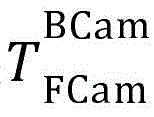 ) And/or display of relative pose to rear camera (transformation)
 ) This may be useful for AR applications.
The calibration parameters can characterize the relative position of the front camera to the display device, and the transformation
The calibration parameters may characterize characteristics of the display device, such as a front camera notch and/or pixel density (e.g., pixel/centimeter ratio).
In one embodiment, all or some of these parameters are provided by the mobile electronic device Software Development Kit (SDK) or from a pre-built database.
In another embodiment, the headset user obtains intrinsic parameters by performing classical calibration methods on the front and back cameras (e.g. by recording video of a pickup plate).
In another embodiment, the relative position of the rear camera is estimated by a manual user calibration step such as the SPAAM method. The calibration step may include having the user align the virtual object with its real-world counterpart (e.g., marker) at a different location. When alignment has occurred, the user communicates with the mobile electronic device (e.g., via a user-selectable marker, clicker, or sensed gesture). These points are then used to retrieve the transformation between the rear camera and the mobile electronic device (front camera or display device). In one embodiment, the number of points is predefined by the headset manufacturer. In another embodiment, the points may be collected until convergence of the projection is achieved. In another embodiment, after the points are collected, the projection is updated, which can be used to display the real world object representation in the virtual world. When the user determines or the mobile electronic device determines that the alignment satisfies the defined rules, the calibration is complete.
In another embodiment, digital pictures from a camera are used to retrieve the transformation Given the transformations estimated during the previous calibration
 And the characteristics of the mirror/optical element of the headset (which may be defined by the manufacturer), the reflection of the display is used to determine the transformation
 To properly use the displayed reflected pose, some arbitrary shape (e.g., a highlighted corner) may be displayed when the image is captured.
In another embodiment, using information from the previously described embodiments, and using the displayed background image along with the shape from the previous embodiments, the size of the screen and/or the pixel density (e.g., pixel to centimeter ratio) can be estimated. The same digital picture may also be used to detect display characteristics such as screen shape (e.g., a screen having a notched portion to accommodate an earpiece, camera, microphone, etc.).
The corresponding operations that may be performed by a mobile electronic device are illustrated in the flowchart of fig. 8, according to one embodiment. Referring to fig. 8, the operation displays 800 a calibration pattern on the display device to cause the camera to capture a portion of the calibration pattern within a digital picture or another digital picture by reflecting a portion of the calibration pattern from the surface of the headset and/or from the eye of the user. The operation determines 802 a size of the display device and/or a pixel density of the display device based on the determination of the size of the feature within the portion of the calibration pattern. The operation may then store 804 an indication of the size of the display device and/or the pixel density of the display device in a data structure of calibration parameters in memory.
FIG. 9 is a flowchart of operations that may be performed by a mobile electronic device, according to one embodiment. Referring to fig. 9, the operations may include displaying 900 an image on a display device. The camera may be operated to capture reflections of images displayed by the display device and reflected by the surface of the headset and/or by the eyes of the user. The operation may determine 902 a shape of the display device based on the determination of the shape of the reflected image and store 904 an indication of the shape of the display device in a data structure of calibration parameters in a memory.
Cloud implementation
Some or all of the operations described above as being performed by a mobile electronic device may alternatively be performed by another node that is part of a network cloud computing resource. For example, these operations may be performed as network functions by a cloud server or cloud resources of a network operator (e.g., a game or other entertainment server, a map travel routing server, an e-commerce server, etc.).
Example Mobile electronic device configuration
Fig. 10 is a block diagram of components of a mobile electronic device 120 configured to operate in accordance with some other embodiments of the present disclosure. The mobile electronic device 120 may include a camera (e.g., front camera 122, rear camera 1050, and/or multiple front/rear cameras), a display device 1040, at least one processor circuit 1006 (processor), and at least one memory 1010 (memory). The mobile electronic device 120 may also include wireless network interface circuitry 1030, a motion and/or orientation sensor 1060, and/or a speaker 1070. The sensors 1060 may include an inertial measurement unit that outputs signals processed by the processor 1006 to determine the pose and/or movement of the mobile electronic device 120. The wireless network interface circuit 1030 may be configured to communicate with another electronic device over a wireless (e.g., Wi-Fi, bluetooth, cellular, etc.) network interface.
A processor 1006 is operatively connected to these various components. The memory 1010 stores program code 1012 that is executed by the processor 1006 to perform operations. The processor 1006 may comprise one or more data processing circuits, such as general and/or special purpose processors (e.g., microprocessors and/or digital signal processors), which may be collocated or distributed over one or more data networks. The processor 1006 is configured to execute computer program instructions in program code 1012 in memory 1010 (described below as a computer-readable medium) to perform some or all of the operations and methods for one or more embodiments disclosed herein for a mobile electronic device.
Further definitions and examples:
in the above description of various embodiments of the inventive concept, it is to be understood that the terminology used herein is for the purpose of describing particular embodiments only and is not intended to be limiting of the inventive concept. Unless otherwise defined, all terms (including technical and scientific terms) used herein have the same meaning as commonly understood by one of ordinary skill in the art to which the inventive concept belongs. It will be understood that terms, such as those defined in commonly used dictionaries, should be interpreted as having a meaning that is consistent with their meaning in the context of this specification and the relevant art and will not be interpreted in an idealized or overly formal sense unless expressly so defined herein.
When an element is referred to as being "connected," "coupled," "responsive" to another element or variations thereof, it can be directly connected, coupled, or responsive to the other element or intervening elements may be present. In contrast, when an element is referred to as being "directly connected to," "directly coupled to," "directly responsive to" another element or variations thereof, there are no intervening elements present. Like reference numerals refer to like elements throughout. Further, "coupled," "connected," "responsive," or variations thereof as used herein may include wirelessly coupled, connected, or responsive. As used herein, the singular forms "a", "an" and "the" are intended to include the plural forms as well, unless the context clearly indicates otherwise. Well-known functions or constructions may not be described in detail for brevity and/or clarity. The term "and/or" includes any and all combinations of one or more of the items listed in association.
It will be understood that, although the terms first, second, third, etc. may be used herein to describe various elements/operations, these elements/operations should not be limited by these terms. These terms are only used to distinguish one element/operation from another element/operation. Thus, a first element/operation in some embodiments may be termed a second element/operation in other embodiments without departing from the teachings of the present inventive concept. Throughout the specification, the same reference numerals or the same reference symbols denote the same or similar elements.
As used herein, the terms "comprising," "comprises," "comprising," "includes," including, "includes" and "including," or variations thereof, are open-ended and include one or more stated features, integers, elements, steps, components, functions, or combinations thereof, but do not preclude the presence or addition of one or more other features, integers, elements, steps, components, functions, or combinations thereof. Further, as used herein, the common abbreviation "e.g., (e.g.)" derived from the latin phrase "exempli gratia," can be used to introduce or specify one or more general examples of a previously mentioned item, and is not intended as a limitation on that item. The common abbreviation "i.e. (i.e.)") derived from the latin phrase "est" may be used to designate a more broadly recited specific item.
Example embodiments are described herein with reference to block diagrams and/or flowchart illustrations of computer-implemented methods, apparatus (systems and/or devices) and/or computer program products. It will be understood that blocks of the block diagrams and/or flowchart illustrations, and combinations of blocks in the block diagrams and/or flowchart illustrations, can be implemented by computer program instructions executed by one or more computer circuits. These computer program instructions may be provided to a processor circuit of a general purpose computer circuit, special purpose computer circuit, and/or other programmable data processing circuit to produce a machine, such that the instructions, which execute via the processor of the computer and/or other programmable data processing apparatus, transform and control transistors, values stored in memory locations, and other hardware components within such circuits to implement the functions/acts specified in the block diagrams and/or flowchart block or blocks, and thereby create means (functions) and/or structures for implementing the functions/acts specified in the block diagrams and/or flowchart block or blocks.
These computer program instructions may also be stored in a tangible computer-readable medium that can direct a computer or other programmable data processing apparatus to function in a particular manner, such that the instructions stored in the computer-readable medium produce an article of manufacture including instructions which implement the function/act specified in the block diagrams and/or flowchart block or blocks. Accordingly, embodiments of the inventive concepts may be implemented in hardware and/or software (including firmware, stored software, microcode, etc.) running on a processor, such as a digital signal processor, which may be collectively referred to as a "circuit," "module," or variations thereof.
It should also be noted that, in some alternative implementations, the functions/acts noted in the blocks may occur out of the order noted in the flowcharts. For example, two blocks shown in succession may, in fact, be executed substantially concurrently, or the blocks may sometimes be executed in the reverse order, depending upon the functionality/acts involved. Furthermore, the functionality of a given block of the flowchart and/or block diagrams may be separated into multiple blocks and/or the functionality of two or more blocks of the flowchart and/or block diagrams may be at least partially integrated. Finally, other blocks may be added/inserted between the illustrated blocks and/or blocks/operations may be omitted without departing from the scope of the inventive concept. Further, although some of the figures include arrows on communication paths to illustrate the primary direction of communication, it is to be understood that communication may occur in the opposite direction to the depicted arrows.
Many variations and modifications may be made to the embodiments without substantially departing from the principles of the present inventive concept. All such changes and modifications are intended to be included herein within the scope of the present inventive concept. Accordingly, the above-described subject matter is to be considered illustrative, and not restrictive, and the appended examples are intended to cover all such modifications, enhancements, and other embodiments, which fall within the spirit and scope of the inventive concept. Thus, to the maximum extent allowed by law, the scope of the present inventive concept is to be determined by the broadest permissible interpretation of the following examples of embodiments and their equivalents, and shall not be restricted or limited by the foregoing detailed description.
Claims (34)
Applications Claiming Priority (1)
| Application Number | Priority Date | Filing Date | Title |
|---|---|---|---|
| PCT/EP2018/082087 WO2020104027A1 (en) | 2018-11-21 | 2018-11-21 | Calibration of mobile electronic devices connected to headsets wearable by users |
Publications (2)
| Publication Number | Publication Date |
|---|---|
| CN113168004A true CN113168004A (en) | 2021-07-23 |
| CN113168004B CN113168004B (en) | 2023-01-06 |
Family
ID=64500362
Family Applications (1)
| Application Number | Title | Priority Date | Filing Date |
|---|---|---|---|
| CN201880099633.9A Active CN113168004B (en) | 2018-11-21 | 2018-11-21 | Calibration of mobile electronic devices connected to user-wearable headsets |
Country Status (7)
| Country | Link |
|---|---|
| US (3) | US11321874B2 (en) |
| EP (1) | EP3884333B1 (en) |
| CN (1) | CN113168004B (en) |
| AR (1) | AR117131A1 (en) |
| ES (1) | ES2927281T3 (en) |
| MX (1) | MX2021005937A (en) |
| WO (1) | WO2020104027A1 (en) |
Families Citing this family (2)
| Publication number | Priority date | Publication date | Assignee | Title |
|---|---|---|---|---|
| US20240046577A1 (en) | 2022-08-05 | 2024-02-08 | Samsung Electronics Co., Ltd. | Video See-Through Augmented Reality |
| US12567216B2 (en) | 2023-05-19 | 2026-03-03 | International Business Machines Corporation | Augmented-reality-interface conflation identification |
Citations (7)
| Publication number | Priority date | Publication date | Assignee | Title |
|---|---|---|---|---|
| CN105573486A (en) * | 2014-05-30 | 2016-05-11 | 索尼电脑娱乐美国公司 | Head mounted device (HMD) system having interface with mobile computing device |
| US20160381286A1 (en) * | 2015-06-24 | 2016-12-29 | Beijing Lenovo Software Ltd. | Control Method, Camera Device and Electronic Equipment |
| CN107004279A (en) * | 2014-12-10 | 2017-08-01 | 微软技术许可有限责任公司 | Natural user interface camera calibrated |
| US20170221270A1 (en) * | 2016-02-03 | 2017-08-03 | Disney Enterprises, Inc. | Self calibration for smartphone goggles |
| WO2017156486A1 (en) * | 2016-03-11 | 2017-09-14 | Oculus Vr, Llc | Corneal sphere tracking for generating an eye model |
| CN107533233A (en) * | 2015-03-05 | 2018-01-02 | 奇跃公司 | System and method for augmented reality |
| US20180181196A1 (en) * | 2016-12-22 | 2018-06-28 | Samsung Electronics Co., Ltd. | Method for displaying image, storage medium, and electronic device |
Family Cites Families (5)
| Publication number | Priority date | Publication date | Assignee | Title |
|---|---|---|---|---|
| CN206990924U (en) * | 2016-03-06 | 2018-02-09 | 赵山山 | One kind suction mobile phone type VR glasses |
| CN105929543A (en) * | 2016-06-18 | 2016-09-07 | 深圳晨芯时代科技有限公司 | Virtual reality device, virtual reality glass box thereof and virtual reality plate |
| US10714121B2 (en) * | 2016-07-27 | 2020-07-14 | Vocollect, Inc. | Distinguishing user speech from background speech in speech-dense environments |
| US10503247B2 (en) | 2017-05-09 | 2019-12-10 | Microsoft Technology Licensing, Llc | Calibration of stereo cameras and handheld object |
| US10732226B2 (en) * | 2017-05-26 | 2020-08-04 | Hand Held Products, Inc. | Methods for estimating a number of workflow cycles able to be completed from a remaining battery capacity |
-
2018
- 2018-11-21 MX MX2021005937A patent/MX2021005937A/en unknown
- 2018-11-21 CN CN201880099633.9A patent/CN113168004B/en active Active
- 2018-11-21 WO PCT/EP2018/082087 patent/WO2020104027A1/en not_active Ceased
- 2018-11-21 ES ES18810954T patent/ES2927281T3/en active Active
- 2018-11-21 EP EP18810954.0A patent/EP3884333B1/en active Active
- 2018-11-21 US US16/500,976 patent/US11321874B2/en active Active
-
2019
- 2019-11-20 AR ARP190103408A patent/AR117131A1/en active IP Right Grant
-
2022
- 2022-03-29 US US17/706,731 patent/US11854234B2/en active Active
-
2023
- 2023-10-31 US US18/498,483 patent/US12277734B2/en active Active
Patent Citations (7)
| Publication number | Priority date | Publication date | Assignee | Title |
|---|---|---|---|---|
| CN105573486A (en) * | 2014-05-30 | 2016-05-11 | 索尼电脑娱乐美国公司 | Head mounted device (HMD) system having interface with mobile computing device |
| CN107004279A (en) * | 2014-12-10 | 2017-08-01 | 微软技术许可有限责任公司 | Natural user interface camera calibrated |
| CN107533233A (en) * | 2015-03-05 | 2018-01-02 | 奇跃公司 | System and method for augmented reality |
| US20160381286A1 (en) * | 2015-06-24 | 2016-12-29 | Beijing Lenovo Software Ltd. | Control Method, Camera Device and Electronic Equipment |
| US20170221270A1 (en) * | 2016-02-03 | 2017-08-03 | Disney Enterprises, Inc. | Self calibration for smartphone goggles |
| WO2017156486A1 (en) * | 2016-03-11 | 2017-09-14 | Oculus Vr, Llc | Corneal sphere tracking for generating an eye model |
| US20180181196A1 (en) * | 2016-12-22 | 2018-06-28 | Samsung Electronics Co., Ltd. | Method for displaying image, storage medium, and electronic device |
Also Published As
| Publication number | Publication date |
|---|---|
| EP3884333A1 (en) | 2021-09-29 |
| AR117131A1 (en) | 2021-07-14 |
| ES2927281T3 (en) | 2022-11-03 |
| WO2020104027A1 (en) | 2020-05-28 |
| BR112021009393A2 (en) | 2021-08-10 |
| US20220215586A1 (en) | 2022-07-07 |
| US20210335011A1 (en) | 2021-10-28 |
| MX2021005937A (en) | 2021-07-02 |
| US11854234B2 (en) | 2023-12-26 |
| EP3884333B1 (en) | 2022-08-10 |
| US12277734B2 (en) | 2025-04-15 |
| US11321874B2 (en) | 2022-05-03 |
| US20240062424A1 (en) | 2024-02-22 |
| CN113168004B (en) | 2023-01-06 |
Similar Documents
| Publication | Publication Date | Title |
|---|---|---|
| CN111010560B (en) | Anti-distortion adjustment method, device and virtual reality system for head-mounted display device | |
| US10643334B2 (en) | Image presentation control methods and image presentation control apparatuses | |
| CN110377148B (en) | Computer readable medium, method of training object detection algorithm and training device | |
| US9514524B2 (en) | Optical distortion compensation | |
| US11238616B1 (en) | Estimation of spatial relationships between sensors of a multi-sensor device | |
| US12277734B2 (en) | Calibration of mobile electronic devices connected to headsets wearable by users | |
| WO2020255766A1 (en) | Information processing device, information processing method, program, projection device, and information processing system | |
| KR101690646B1 (en) | Camera driving device and method for see-through displaying | |
| JP2018084954A (en) | Program, posture derivation method, posture derivation device | |
| KR20210017081A (en) | Apparatus and method for displaying graphic elements according to object | |
| CN111095348A (en) | Camera-Based Transparent Display | |
| WO2018042074A1 (en) | A method, apparatus and computer program product for indicating a seam of an image in a corresponding area of a scene | |
| WO2020189450A1 (en) | Device provided with plurality of markers | |
| KR101148508B1 (en) | A method and device for display of mobile device, and mobile device using the same | |
| CN110874867A (en) | Display method, display device, terminal equipment and storage medium | |
| US20220206303A1 (en) | Portable electronic device for mixed reality headset | |
| CN113848644B (en) | Focal length adjusting method, device and equipment of AR glasses and readable storage medium | |
| CN116468877A (en) | Method, host and computer-readable storage medium for adjusting virtual object | |
| BR112021009393B1 (en) | MOBILE ELECTRONIC DEVICE, METHOD FOR PERFORMING OPERATIONS THROUGH A PROCESSOR OF A MOBILE ELECTRONIC DEVICE, AND A NON-TRAINER COMPUTER READABLE MEDIUM | |
| CN115700764B (en) | Control method, tracking system and non-transitory computer readable medium | |
| CN121166059A (en) | Adjusting display of images based on device location |
Legal Events
| Date | Code | Title | Description |
|---|---|---|---|
| PB01 | Publication | ||
| PB01 | Publication | ||
| SE01 | Entry into force of request for substantive examination | ||
| SE01 | Entry into force of request for substantive examination | ||
| GR01 | Patent grant | ||
| GR01 | Patent grant |