CN112472003B - Detachable endoscope with metal wire buffering function - Google Patents
Detachable endoscope with metal wire buffering function Download PDFInfo
- Publication number
- CN112472003B CN112472003B CN202010914260.5A CN202010914260A CN112472003B CN 112472003 B CN112472003 B CN 112472003B CN 202010914260 A CN202010914260 A CN 202010914260A CN 112472003 B CN112472003 B CN 112472003B
- Authority
- CN
- China
- Prior art keywords
- buffer
- rack
- metal wire
- wire
- hole
- Prior art date
- Legal status (The legal status is an assumption and is not a legal conclusion. Google has not performed a legal analysis and makes no representation as to the accuracy of the status listed.)
- Active
Links
Images








Classifications
-
- A—HUMAN NECESSITIES
- A61—MEDICAL OR VETERINARY SCIENCE; HYGIENE
- A61B—DIAGNOSIS; SURGERY; IDENTIFICATION
- A61B1/00—Instruments for performing medical examinations of the interior of cavities or tubes of the body by visual or photographical inspection, e.g. endoscopes; Illuminating arrangements therefor
- A61B1/00064—Constructional details of the endoscope body
- A61B1/00105—Constructional details of the endoscope body characterised by modular construction
-
- A—HUMAN NECESSITIES
- A61—MEDICAL OR VETERINARY SCIENCE; HYGIENE
- A61B—DIAGNOSIS; SURGERY; IDENTIFICATION
- A61B1/00—Instruments for performing medical examinations of the interior of cavities or tubes of the body by visual or photographical inspection, e.g. endoscopes; Illuminating arrangements therefor
- A61B1/00064—Constructional details of the endoscope body
- A61B1/00071—Insertion part of the endoscope body
- A61B1/0008—Insertion part of the endoscope body characterised by distal tip features
- A61B1/00101—Insertion part of the endoscope body characterised by distal tip features the distal tip features being detachable
-
- A—HUMAN NECESSITIES
- A61—MEDICAL OR VETERINARY SCIENCE; HYGIENE
- A61B—DIAGNOSIS; SURGERY; IDENTIFICATION
- A61B1/00—Instruments for performing medical examinations of the interior of cavities or tubes of the body by visual or photographical inspection, e.g. endoscopes; Illuminating arrangements therefor
- A61B1/00112—Connection or coupling means
-
- A—HUMAN NECESSITIES
- A61—MEDICAL OR VETERINARY SCIENCE; HYGIENE
- A61B—DIAGNOSIS; SURGERY; IDENTIFICATION
- A61B1/00—Instruments for performing medical examinations of the interior of cavities or tubes of the body by visual or photographical inspection, e.g. endoscopes; Illuminating arrangements therefor
- A61B1/00112—Connection or coupling means
- A61B1/00114—Electrical cables in or with an endoscope
-
- A—HUMAN NECESSITIES
- A61—MEDICAL OR VETERINARY SCIENCE; HYGIENE
- A61B—DIAGNOSIS; SURGERY; IDENTIFICATION
- A61B1/00—Instruments for performing medical examinations of the interior of cavities or tubes of the body by visual or photographical inspection, e.g. endoscopes; Illuminating arrangements therefor
- A61B1/00112—Connection or coupling means
- A61B1/00121—Connectors, fasteners and adapters, e.g. on the endoscope handle
-
- A—HUMAN NECESSITIES
- A61—MEDICAL OR VETERINARY SCIENCE; HYGIENE
- A61B—DIAGNOSIS; SURGERY; IDENTIFICATION
- A61B1/00—Instruments for performing medical examinations of the interior of cavities or tubes of the body by visual or photographical inspection, e.g. endoscopes; Illuminating arrangements therefor
- A61B1/00112—Connection or coupling means
- A61B1/00121—Connectors, fasteners and adapters, e.g. on the endoscope handle
- A61B1/00128—Connectors, fasteners and adapters, e.g. on the endoscope handle mechanical, e.g. for tubes or pipes
-
- A—HUMAN NECESSITIES
- A61—MEDICAL OR VETERINARY SCIENCE; HYGIENE
- A61B—DIAGNOSIS; SURGERY; IDENTIFICATION
- A61B1/00—Instruments for performing medical examinations of the interior of cavities or tubes of the body by visual or photographical inspection, e.g. endoscopes; Illuminating arrangements therefor
- A61B1/005—Flexible endoscopes
- A61B1/0051—Flexible endoscopes with controlled bending of insertion part
- A61B1/0052—Constructional details of control elements, e.g. handles
-
- A—HUMAN NECESSITIES
- A61—MEDICAL OR VETERINARY SCIENCE; HYGIENE
- A61B—DIAGNOSIS; SURGERY; IDENTIFICATION
- A61B1/00—Instruments for performing medical examinations of the interior of cavities or tubes of the body by visual or photographical inspection, e.g. endoscopes; Illuminating arrangements therefor
- A61B1/005—Flexible endoscopes
- A61B1/0051—Flexible endoscopes with controlled bending of insertion part
- A61B1/0057—Constructional details of force transmission elements, e.g. control wires
-
- A—HUMAN NECESSITIES
- A61—MEDICAL OR VETERINARY SCIENCE; HYGIENE
- A61B—DIAGNOSIS; SURGERY; IDENTIFICATION
- A61B1/00—Instruments for performing medical examinations of the interior of cavities or tubes of the body by visual or photographical inspection, e.g. endoscopes; Illuminating arrangements therefor
- A61B1/04—Instruments for performing medical examinations of the interior of cavities or tubes of the body by visual or photographical inspection, e.g. endoscopes; Illuminating arrangements therefor combined with photographic or television appliances
-
- A—HUMAN NECESSITIES
- A61—MEDICAL OR VETERINARY SCIENCE; HYGIENE
- A61B—DIAGNOSIS; SURGERY; IDENTIFICATION
- A61B1/00—Instruments for performing medical examinations of the interior of cavities or tubes of the body by visual or photographical inspection, e.g. endoscopes; Illuminating arrangements therefor
- A61B1/04—Instruments for performing medical examinations of the interior of cavities or tubes of the body by visual or photographical inspection, e.g. endoscopes; Illuminating arrangements therefor combined with photographic or television appliances
- A61B1/05—Instruments for performing medical examinations of the interior of cavities or tubes of the body by visual or photographical inspection, e.g. endoscopes; Illuminating arrangements therefor combined with photographic or television appliances characterised by the image sensor, e.g. camera, being in the distal end portion
-
- A—HUMAN NECESSITIES
- A61—MEDICAL OR VETERINARY SCIENCE; HYGIENE
- A61B—DIAGNOSIS; SURGERY; IDENTIFICATION
- A61B1/00—Instruments for performing medical examinations of the interior of cavities or tubes of the body by visual or photographical inspection, e.g. endoscopes; Illuminating arrangements therefor
- A61B1/04—Instruments for performing medical examinations of the interior of cavities or tubes of the body by visual or photographical inspection, e.g. endoscopes; Illuminating arrangements therefor combined with photographic or television appliances
- A61B1/05—Instruments for performing medical examinations of the interior of cavities or tubes of the body by visual or photographical inspection, e.g. endoscopes; Illuminating arrangements therefor combined with photographic or television appliances characterised by the image sensor, e.g. camera, being in the distal end portion
- A61B1/053—Instruments for performing medical examinations of the interior of cavities or tubes of the body by visual or photographical inspection, e.g. endoscopes; Illuminating arrangements therefor combined with photographic or television appliances characterised by the image sensor, e.g. camera, being in the distal end portion being detachable
-
- A—HUMAN NECESSITIES
- A61—MEDICAL OR VETERINARY SCIENCE; HYGIENE
- A61B—DIAGNOSIS; SURGERY; IDENTIFICATION
- A61B1/00—Instruments for performing medical examinations of the interior of cavities or tubes of the body by visual or photographical inspection, e.g. endoscopes; Illuminating arrangements therefor
- A61B1/313—Instruments for performing medical examinations of the interior of cavities or tubes of the body by visual or photographical inspection, e.g. endoscopes; Illuminating arrangements therefor for introducing through surgical openings, e.g. laparoscopes
-
- F—MECHANICAL ENGINEERING; LIGHTING; HEATING; WEAPONS; BLASTING
- F16—ENGINEERING ELEMENTS AND UNITS; GENERAL MEASURES FOR PRODUCING AND MAINTAINING EFFECTIVE FUNCTIONING OF MACHINES OR INSTALLATIONS; THERMAL INSULATION IN GENERAL
- F16H—GEARING
- F16H19/00—Gearings comprising essentially only toothed gears or friction members and not capable of conveying indefinitely-continuing rotary motion
- F16H19/02—Gearings comprising essentially only toothed gears or friction members and not capable of conveying indefinitely-continuing rotary motion for interconverting rotary or oscillating motion and reciprocating motion
- F16H19/04—Gearings comprising essentially only toothed gears or friction members and not capable of conveying indefinitely-continuing rotary motion for interconverting rotary or oscillating motion and reciprocating motion comprising a rack
- F16H19/043—Gearings comprising essentially only toothed gears or friction members and not capable of conveying indefinitely-continuing rotary motion for interconverting rotary or oscillating motion and reciprocating motion comprising a rack for converting reciprocating movement in a continuous rotary movement or vice versa, e.g. by opposite racks engaging intermittently for a part of the stroke
-
- F—MECHANICAL ENGINEERING; LIGHTING; HEATING; WEAPONS; BLASTING
- F16—ENGINEERING ELEMENTS AND UNITS; GENERAL MEASURES FOR PRODUCING AND MAINTAINING EFFECTIVE FUNCTIONING OF MACHINES OR INSTALLATIONS; THERMAL INSULATION IN GENERAL
- F16L—PIPES; JOINTS OR FITTINGS FOR PIPES; SUPPORTS FOR PIPES, CABLES OR PROTECTIVE TUBING; MEANS FOR THERMAL INSULATION IN GENERAL
- F16L39/00—Joints or fittings for double-walled or multi-channel pipes or pipe assemblies
Landscapes
- Health & Medical Sciences (AREA)
- Life Sciences & Earth Sciences (AREA)
- Surgery (AREA)
- Engineering & Computer Science (AREA)
- Biomedical Technology (AREA)
- Molecular Biology (AREA)
- Pathology (AREA)
- Radiology & Medical Imaging (AREA)
- Nuclear Medicine, Radiotherapy & Molecular Imaging (AREA)
- Biophysics (AREA)
- Physics & Mathematics (AREA)
- Heart & Thoracic Surgery (AREA)
- Medical Informatics (AREA)
- Optics & Photonics (AREA)
- Animal Behavior & Ethology (AREA)
- General Health & Medical Sciences (AREA)
- Public Health (AREA)
- Veterinary Medicine (AREA)
- Mechanical Engineering (AREA)
- General Engineering & Computer Science (AREA)
- Endoscopes (AREA)
- Instruments For Viewing The Inside Of Hollow Bodies (AREA)
Abstract
The invention provides a detachable endoscope with a buffer function. The invention comprises a dismounting unit, wherein an operation part and an insertion part are combined in a mutually dismountable way, the operation part bends the front end of the insertion part provided with an illumination shooting part, the dismounting unit comprises a first dismounting module and a second dismounting module, and the first dismounting module comprises a first module body; the first rack, the second rack, the third rack and the fourth rack; a first pinion gear; a second pinion gear; and a gear shaft.
Description
Technical Field
The present invention relates to an endoscope, and more particularly, to a detachable endoscope having a wire buffer function, in which, irrespective of a length error caused by a bending deformation portion occurring in the middle of the length of an insertion portion, respective ends of a coupling structure corresponding to a coupled structure of an operation portion are aligned at predetermined positions of the end of the insertion portion in the same manner all the time, and an operation of selectively locking a coupling member connecting the insertion portion and the coupled member of the operation portion and an operation of bending a distal end of the insertion portion in an up-down direction or a left-right direction can be performed in linkage.
Background
In general, in an operation using an endoscope, after an endoscope provided with a camera and an operation tool are inserted through a small hole, an affected part of a patient is observed by an image captured by the endoscope in the body and the operation is performed, instead of cutting a human body in a large range.
In particular, since the incision site of the endoscopic surgery performed from the beginning of the laparoscopic surgery is small compared to the open surgery, the scar site is also small, and the amount of bleeding is also small, so that the patient can recover more quickly after the completion of the surgery.
Recently, technology has been developed such that endoscopic surgery can be performed for almost all the surgeries for which open surgery is required, and furthermore, the application of endoscopic surgery to other medical fields has been increasing.
In a conventional general endoscope, an insertion portion to be inserted into a human body and an operation portion to control the insertion portion are integrally formed, and a plurality of pipes and guides penetrating the inside of each portion are built in, and in particular, an imaging device such as an expensive CCD is provided at the tip of the insertion portion to be inserted into the human body, so that it is difficult to separate the insertion portion from the operation portion only to perform new alternation.
(patent document 1) KR10-0673412B1
(patent document 2) KR10-1091999B1
(patent document 3) KR10-1783225B1
Patent documents 1 to 3 disclose detachable endoscopes of various forms which are used in connection with each other by combining an insertion portion to be inserted into the body and an operation portion to operate the insertion portion, or which are stored separately from each other, in accordance with a trend of enhancing a sanitary function of the medical endoscope.
In the detachable endoscope disclosed in this patent document, if the insertion portion completely detached from the operation portion is wound into a substantially circular shape and stored, or if the middle of the length of the insertion portion is forcibly bent and deformed by an external factor, at least one bending deformation portion is formed in the length space of the insertion portion in which a plurality of wires aligned in the longitudinal direction are disposed in the internal space.
In this case, the inner curved portion and the outer curved portion are formed on the inner side and the outer side of the curved deformation portion, respectively, and the outer radius of curvature formed by the outer curved portion is larger than the inner radius of curvature formed by the inner curved portion based on the virtual reference point, and therefore, the radius of curvature of the wire adjacent to the outer curved portion is larger than the radius of curvature of the wire adjacent to the inner curved portion.
That is, if at least one bending deformation portion is formed in the middle of the length of the insertion portion, a length error occurs in which the positions of the other ends of the plurality of wires, one ends of which are limited by the inside of the distal end of the insertion portion, become different from each other.
In this case, among the plurality of coupling structures provided at the other ends of the plurality of wires in which the length error caused by the bending deformation portion occurs, the coupling structure corresponding to the wire near the outer bending portion enters the distance corresponding to the length error further toward the inside of the insertion portion than the other end of the other coupling structure corresponding to the wire near the inner bending portion, and therefore, the plurality of coupling structures are aligned at different positions, respectively.
Under such a condition, a user performs an operation of coupling the insertion portion and the operation portion to each other so as to couple the coupled structure of the operation portion and the coupled structure of the insertion portion to each other, in a state where the insertion portion is always kept in a straight line so that a bending deformation portion having a length error is prevented from being formed in the middle of the length of the insertion portion.
Further, when the bending deformation portion is formed by at least one bending deformation portion formed in the middle of the length of the insertion portion so as to prevent the end portion of the coupling structure of the insertion portion from being forced to enter the inside of the insertion portion by an additional restricting structure, the wire is elongated by tension applied to the wire positioned at the inside bending portion and the outside bending portion when the bending deformation portion is formed, whereby the operation of bending the distal end of the insertion portion in the up-down direction and the left-right direction cannot be accurately performed.
In particular, since tension applied to the wire adjacent to the outer bent portion is relatively large, breakage occurs in the middle of the length of the wire as the elongated wire is excessively elongated and deformed, and thus, a fatal problem of losing the function of the endoscope occurs.
Disclosure of Invention
Accordingly, the present invention has been made to solve the above-described problems, and an object of the present invention is to provide a detachable endoscope having a buffer function in which each end portion of a coupling structure corresponding to a coupled structure of an operation portion is aligned at a predetermined position of an end portion of an insertion portion in a constant manner regardless of a length error caused by a bending deformation portion formed in the middle of the length of the insertion portion.
Further, an object of the present invention is to provide a detachable endoscope having a buffer function in which, when an operation portion is selectively rotated, an operation of selectively locking a coupling piece coupling an insertion portion and a coupled piece of the operation portion can be performed in conjunction with an operation of bending a distal end of the insertion portion in an up-down direction or a left-right direction, thereby improving convenience in use.
The technical problems to be solved by the present invention are not limited to the above-mentioned technical problems, and other technical problems not mentioned can be clearly understood by those skilled in the art to which the present invention pertains from the following description.
As a specific means for achieving the above object, a preferred embodiment of the present invention provides a detachable endoscope including a detachable unit for detachably coupling an operation unit and an insertion unit to each other, the operation unit bending a distal end of the insertion unit provided with an illumination imaging unit, the detachable endoscope including: the first disassembly and assembly module is connected with the other ends of the first working metal wire, the second working metal wire, the third working metal wire and the fourth working metal wire, and one ends of the first working metal wire, the second working metal wire, the third working metal wire and the fourth working metal wire are connected with the front end of the inside of the insertion part and are arranged at the rear end of the insertion part; and a second detachable module connected to the first, second, third, and fourth connection wires of the direction conversion unit and provided at a front end of the operation unit, the direction conversion unit converting rotational motion into linear motion in the operation unit, the first detachable module including: a first module body that is penetrated in the longitudinal direction to form a first linear guide hole, a second linear guide hole, a third linear guide hole, and a fourth linear guide hole, and is penetrated in the thickness direction to form a center arrangement hole; a first rack, a second rack, a third rack and a fourth rack, one end of which is correspondingly combined with the first working metal wire, the second working metal wire, the third working metal wire and the fourth working metal wire by taking a first buffer part as a medium, and is assembled in the first linear guide hole, the second linear guide hole, the third linear guide hole and the fourth linear guide hole; a first pinion gear which is in gear engagement with the first rack gear and the second rack gear; a second pinion gear engaged between the third rack and the fourth rack; and a gear shaft, wherein the first pinion and the second pinion are assembled with a predetermined vertical interval therebetween, and fixedly provided in the center arrangement hole, and the first buffer portion includes: a first buffer body integrally formed with respective ends of the first, second, third, and fourth working wires; a first buffer wire hole having a predetermined length formed in one end of each of the first rack, the second rack, the third rack, and the fourth rack, the first buffer body being inserted and disposed so as to be capable of reciprocating; and a first buffer stopper portion that forms an inner hole through which the working wire provided with the first buffer body is disposed, wherein the first, second, third and fourth coupling members provided at the ends of the first, second, third and fourth racks are disposed in an aligned manner at the same position of the end of the first attachment/detachment module, the first buffer portion being assembled at the end of the opening of the first buffer wire hole so as to prevent the outside of the first buffer body from being detached, and wherein the first buffer portion compensates for a length error of the first, second, third and fourth working wires due to a bending deformation portion formed in the middle of the length of the insertion portion separated from the operation portion.
In this case, the first buffer stop portion may be a hollow cylindrical body having a slit cut along a longitudinal direction.
In this case, the first buffer stop portion may include a fixing portion including an assembly hole through which a fastening member is disposed, the fastening member being fastened to fastening holes formed at respective ends of the first rack, the second rack, the third rack, and the fourth rack.
In this case, a ring-shaped first inner locking portion may be provided on an inner surface of the inlet end of the first buffer wire hole, and the ring-shaped first inner locking portion may be in contact with an end portion of the first buffer stop portion to form a circular hole through which the first buffer body may pass.
In this case, the first, second, third and fourth racks may include: a linear rod having a predetermined length slidably assembled in the first, second, third and fourth linear guide holes; and a linear gear tooth formed protruding from the linear bar so as to mesh with a circular gear tooth formed on the outer circumferential surfaces of the first pinion gear and the second pinion gear.
In this case, each of the linear bars of the first, second, third and fourth racks may include a moving body moving along a plurality of linear guide slits cut at both side surfaces of the first module body.
In this case, in the gear shaft, a first annular groove and a second annular groove may be formed in a recessed manner on outer surfaces corresponding to the first pinion and the second pinion, and a first elastic ring and a second elastic ring that elastically contact inner peripheral surfaces and outer peripheral surfaces of the first pinion and the second pinion may be provided in the first annular groove and the second annular groove.
In this case, the first detachable module may include a wire supporting part supporting the linear movement of the first, second, third and fourth working wires, the wire supporting part including: the first support body, the second support body, the third support body and the fourth support body are penetrated to form support holes for correspondingly inserting the first working metal wire, the second working metal wire, the third working metal wire and the fourth working metal wire; the first support body, the second support body, the third support body and the fourth support body are fixedly arranged at one end part of the support block; and a connection bracket for assembling the support block at one end of the first module body.
Further, a preferred embodiment of the present invention provides a detachable endoscope having a wire buffer function, the detachable endoscope having a detachable unit for detachably coupling an operation unit to the insertion unit, the operation unit bending a distal end of the insertion unit provided with an illumination imaging unit, the detachable endoscope having a wire buffer function, the detachable unit comprising: the first disassembly and assembly module is connected with the other ends of the first working metal wire, the second working metal wire, the third working metal wire and the fourth working metal wire, and one ends of the first working metal wire, the second working metal wire, the third working metal wire and the fourth working metal wire are connected with the front end of the inside of the insertion part and are arranged at the rear end of the insertion part; the second dismouting module, be connected with first connection metal wire, second connection metal wire, third connection metal wire and the fourth connection metal wire of direction conversion portion, set up in the front end of operating portion, above-mentioned direction conversion portion is with rotary motion conversion linear motion in above-mentioned operating portion, above-mentioned second dismouting module includes: a second module body which is disposed inside the front end of the operation section and has a first straight-line through-hole, a second straight-line through-hole, a third straight-line through-hole, and a fourth straight-line through-hole formed therethrough in a longitudinal direction; and first, second, third and fourth connecting shafts, each of which has one end coupled to the first, second, third and fourth connecting wires by a second buffer portion as a medium, and is provided in the first, second, third and fourth linear through holes so as to be reciprocally movable, the other ends of the first, second, third and fourth connecting shafts including first, second, third and fourth coupled members selectively engaged with the first, second, third and fourth coupled members provided in the first detachable module, the second buffer part includes a second buffer body integrally formed with each end of the first, second, third and fourth connection wires, a second buffer wire hole of a predetermined length is provided in each end of the first, second, third and fourth connection shafts so that the second buffer body is inserted and disposed in a reciprocable manner, the second buffer part includes a second buffer stopper part assembled at an end of an opening of the second buffer wire hole for preventing an external detachment of the second buffer body, and when the operation part is selectively rotated, one of the first, second, third and fourth connection shafts is moved toward the operation part side by interference of the second buffer body and the second buffer stopper part, and the remaining connection shaft is standby and stopped in the front end of the operation part, whereby, one of the first coupling member, the second coupling member, the third coupling member, and the fourth coupling member of the first detachable module is selectively engaged with one of the first coupled member, the second coupled member, the third coupled member, and the fourth coupled member of the second detachable module.
In this case, an annular second inner locking portion may be provided on an inner surface of the inlet end of the second damper wire hole, and a circular hole through which the second damper body can pass may be formed in contact with an end portion of the second damper locking portion.
In this case, the first, second, third and fourth connecting shafts may include: a working rod having at least one elastic body, the working rod being inserted into the first, second, third, and fourth linear through holes so as to be capable of reciprocating movement; a guide pin provided at one end of the working rod so as to move in a curved shape along a complex guide slit formed by cutting the second module body and to rotationally displace the working rod; and a first coupled member, a second coupled member, a third coupled member, and a fourth coupled member, which are provided at one end of the working rod having the guide pin, so as to be selectively engaged with the first coupled member, the second coupled member, the third coupled member, and the fourth coupled member.
In this case, the second module body may include: a body block through which the first, second, third, and fourth linear through holes are formed, and the composite guide slit is cut out on an outer surface; a first cover plate penetrating through a plurality of first inlet and outlet holes formed at one end of the first, second, third and fourth connecting shafts, and disposed at one end of the body block; and a second cover plate penetrating through a plurality of second access holes corresponding to the first, second, third and fourth straight through holes and provided at the other end of the body block.
In this case, one end of the elastic body may be in contact with the first cover plate, and the other end may be supported in contact with a large diameter portion of the lever provided with the guide pin.
In this case, the above-mentioned complex type guide slit may include: a curved section formed by curved slits extending in a curved shape from both side surfaces of the body block to the upper surface and the lower surface; and a linear section formed by linear slits extending in a linear shape on the upper and lower surfaces of the body block.
In this case, the first, second, third and fourth coupled members may include slot-type locking holes exposing the inner cavity portions to the first, second, third and fourth coupled members, and the first, second, third and fourth coupled members may include locking members with distal ends thereof spread out to both sides.
According to the above preferred embodiments of the present invention, the present invention has the following effects.
The first, second, third and fourth working wires of the insertion portion are connected to the first, second, third and fourth racks provided in the first detachable module with the first buffer portion as a medium, whereby, when the insertion portion separated from the operation portion is stored and handled, the respective ends of the coupled structure of the operation portion and the coupling structure of the insertion portion corresponding thereto are arranged at predetermined positions of the ends of the insertion portion in the same manner all the time, irrespective of a length error caused by a bending deformation portion occurring in the middle of the length of the separated insertion portion, and therefore, when the operation portion is coupled to the insertion portion, the coupling of the coupling piece and the coupled piece can be smoothly performed without occurrence of a locking failure.
The first connecting wire, the second connecting wire, the third connecting wire and the fourth connecting wire of the operation part are connected with the first connecting shaft, the second connecting shaft, the third connecting shaft and the fourth connecting shaft which are arranged on the second dismounting module by taking the second buffer part as a medium, when the operation part selectively rotates, other connecting shafts corresponding to the connecting shafts which are pulled to move by the second buffer part stand by and stop in the front end of the operation part, therefore, one of the first connecting piece, the second connecting piece, the third connecting piece and the fourth connecting piece of the first dismounting module and one of the first connected piece, the second connected piece, the third connected piece and the fourth connected piece of the second dismounting module can be selectively locked and connected, and the corresponding connecting piece and the connected piece are locked and connected, and the action of bending the front end of the insertion part in the upward and downward direction or the left and right direction is executed.
Drawings
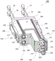
Fig. 1 is an overall perspective view showing a detachable endoscope having a wire buffer function according to an embodiment of the present invention.
Fig. 2 is an enlarged view showing a joint portion between an insertion portion and an operation portion of a detachable endoscope having a wire buffer function according to an embodiment of the present invention.
Fig. 3 is a perspective view showing a detachable unit provided in a detachable endoscope having a wire buffer function according to an embodiment of the present invention.
Fig. 4 is a perspective view showing a first attachment module provided in an attachment unit of an attachment/detachment type endoscope having a wire buffer function according to an embodiment of the present invention.
Fig. 5 is a cross-sectional perspective view showing a first attachment module provided in an attachment unit of an attachment/detachment type endoscope having a wire buffer function according to an embodiment of the present invention.
Fig. 6 is a longitudinal sectional view showing a first attachment module provided in an attachment unit of an attachment-detachment type endoscope having a wire buffer function according to an embodiment of the present invention.
Fig. 7 is an exploded perspective view showing a first attachment module provided to an attachment unit of an attachment/detachment type endoscope having a wire buffer function according to an embodiment of the present invention.
Fig. 8a, 8b and 8c are an assembled view, an exploded view and a cross-sectional view showing a first buffer portion provided in a detachable endoscope having a wire buffer function according to an embodiment of the present invention.
Fig. 9a, 9b and 9c are operation state diagrams of a first detachable module and a first buffer portion of a detachable endoscope having a wire buffer function according to an embodiment of the present invention.
Fig. 10 is a perspective view showing a second attachment module provided to an attachment unit of an attachment/detachment type endoscope having a wire buffer function according to an embodiment of the present invention.
Fig. 11 is a cross-sectional perspective view showing a second attachment module provided in an attachment unit of an attachment/detachment type endoscope having a wire buffer function according to an embodiment of the present invention.
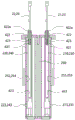
Fig. 12 is a longitudinal sectional view showing a second attachment module provided to an attachment unit of an attachment-detachment type endoscope having a wire buffer function according to an embodiment of the present invention.
Fig. 13 is an exploded perspective view showing a second attachment module provided to an attachment unit of an attachment/detachment type endoscope having a wire buffer function according to an embodiment of the present invention.
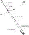
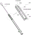
Fig. 14a, 14b and 14c are an assembled view, an exploded view and a cross-sectional view showing a second buffer portion provided in the detachable endoscope having a wire buffer function according to the embodiment of the present invention.
Fig. 15a, 15b and 15c are operational views of a second detachable module that operates in conjunction with a detachable endoscope having a wire buffer function provided in an embodiment of the present invention.
Fig. 16a, 16b and 16c are operation state diagrams of a second buffer portion that operates in conjunction with a second attachment/detachment module provided in an attachment/detachment type endoscope having a wire buffer function according to an embodiment of the present invention.
Description of the reference numerals
1: detachable endoscope
1a: disassembling and assembling unit
10: insertion part
11. 12, 13, 14: first working metal wire, second working metal wire, third working metal wire and fourth working metal wire
20: operation part
21. 22, 23, 24: first, second, third and fourth connecting wires
28. 29: upper operating handle and lower operating handle
100: first dismounting module
110. 120, 130, 140: first rack, second rack, third rack and fourth rack
115. 125, 135, 145: first, second, third and fourth coupling members
150. 160: first pinion and second pinion
170: gear shaft
180: first module body
200: second dismounting module
210. 220, 230, 240: first, second, third and fourth connecting shafts
215. 225, 235, 245: first, second, third and fourth coupled members
410: first buffer part
411: first buffer body
412: first buffer stop part
413: first buffer wire hole
420: second buffer part
421: second buffer body
422: second buffer stop part
423: second buffer wire hole
Detailed Description
Hereinafter, preferred embodiments of the present invention will be described in detail with reference to the accompanying drawings so that those skilled in the art to which the present invention pertains can easily practice the present invention. However, in the course of describing in detail the structural principles of the preferred embodiment of the present invention, a detailed description thereof will be omitted in the event that it is judged that the detailed description of the related well-known functions or structures can obscure the gist of the present invention.
Also, throughout the drawings, the same reference numerals are used for portions that perform similar functions and roles.
In addition, throughout the specification, when one portion is "connected" to another portion, this includes a case of "direct connection" and a case of "indirect connection" with other devices interposed therebetween. Further, unless specifically stated to the contrary, "comprising" a structural element means that other structural elements are also included, and does not mean that other structural elements are excluded.
As shown in fig. 1, a detachable endoscope 1 according to an embodiment of the present invention includes: an insertion section 10, the distal end of which is inserted into the body when performing an endoscopic operation; an operation unit 20 having a plurality of operation handles; a universal joint 30 electrically connected to the endoscope control and management system; and a detachable unit 1a that mechanically connects the insertion section 10 and the operation section 20 to each other before performing an endoscopic operation, or that separates the insertion section 10 from the operation section 20 after performing an operation.
The insertion portion 10 is formed of a tube of flexible material so as to adjust the direction of insertion into the body, and an illumination imaging portion including a light source for illuminating the body and an image sensor for imaging is provided at the distal end.
The operation unit 20 includes: an upper operation handle 28 for bending the front end of the insertion portion inserted into the body in the up-down direction; and a lower operation handle 29 for bending the tip of the insertion portion inserted into the body in the left-right direction.
The direction conversion unit is provided in the operation unit 20, and an upper sprocket (spline), a lower sprocket, an upper chain, and a lower chain are provided in the direction conversion unit, the upper sprocket and the lower sprocket are provided in the upper operation knob and the lower operation knob, respectively, the upper chain and the lower chain are connected to the upper sprocket and the lower sprocket, and when the upper operation knob and the lower operation knob are operated, the upper sprocket and the lower sprocket are rotated to be converted to linear movements by the direction conversion unit, whereby selective rotational movements of the upper operation knob and the lower operation knob are converted to linear movements, and the upper chain and the lower chain are connected to inner ends of the front end of the insertion portion with a plurality of operation wires arranged in the insertion portion as a medium.
By converting a part of the plurality of work wires disposed in the insertion portion into linear motion by the upper and lower sprockets rotating based on selective rotation of the upper and lower operating handles of the user and the upper and lower chains performing reciprocating rectilinear motion, the tip end of the insertion portion is bent in the up-down direction or the left-right direction in the body according to the linear motion of the work wires.
An operation switch and an operation button are provided in the operation portion, and an inlet and an outlet for opening and closing the inlet and the outlet are provided at a rear end of an insertion portion detachably assembled with a front end of the operation portion and a detachable unit as a medium, and an operation port for allowing an operation prop such as an endoscope treatment material having a clip to be moved in and out of the insertion portion when performing an endoscopic operation.
In fig. 1 and 2, an air supply pipe 25b, a water supply pipe 25c, and a suction pipe 25a are provided in an end cover 27 provided at an end of the operation portion, the air supply pipe 25b is for supplying air, the water supply pipe 25c is for supplying water, the suction pipe 25c is for sucking water and air to the outside and discharging the same, and a terminal 26 electrically connected to the illumination imaging portion is provided, while an annular coupling body 15 is provided at a rear end of the insertion portion 10 formed substantially by a cylinder cover, and the annular coupling body 15 is screwed to a female screw portion formed at a front end of the operation portion 20 formed by the cylinder cover.
As shown in fig. 2 and 3, the detachable endoscope 1 according to the preferred embodiment of the present invention includes a detachable unit 1a detachably coupled between the rear end of the insertion portion 10 and the front end of the operation portion 20.
The detachable unit 1a includes: a first detachable module 100 inserted into the insertion portion; a second detachable module 200 inserted into the operation unit and coupled to the first detachable module; and a first buffer portion 410 and a second buffer portion 420.
The first detachable module 100 is disposed in order inside the insertion portion, and is connected to each end of the first work wire 11 and the second work wire 12 so that the tip of the insertion portion is bent in the up-down direction a, and is connected to each end of the third work wire 13 and the fourth work wire 14 so that the tip of the insertion portion is bent in the left-right direction B.
The second detachable module 200 is connected to both ends of an upper chain and a lower chain wound around the upper sprocket and the lower sprocket rotated in the forward and reverse directions by the upper operating handle 28 and the lower operating handle 29, with the first connecting wire 21, the second connecting wire 22, the third connecting wire 23, and the fourth connecting wire 24 as a medium.
The first buffer part 410 provides a buffer function to a connection portion between the first work wire 11, the second work wire 12, the third work wire 13, and the fourth work wire 14 of the insertion part and the first rack 110, the second rack 120, the third rack 130, and the fourth rack 140 provided in the first detachable module 100, and the second buffer part 420 provides a buffer function to a connection portion between the first connection wire 21, the second connection wire 22, the third connection wire 23, and the fourth connection wire 24 of the operation part and the first connection shaft 210, the second connection shaft 220, the third connection shaft 230, and the fourth connection shaft 240 provided in the second detachable module 200.
The first and second connection wires 21 and 22 connected to both ends of the upper chain wound around the upper sprocket are linked with the first and second working wires 11 and 12 disposed in a pair in a regular manner on the upper side of the inside of the insertion portion in the drawing to bend the tip of the insertion portion in the vertical direction, while the third and fourth connection wires 23 and 14 connected to both ends of the lower chain wound around the lower sprocket are linked with the third and fourth working wires 13 and 14 disposed in a pair in a regular manner on the lower side of the inside of the insertion portion in the drawing to bend the tip of the insertion portion in the horizontal direction.
The rotation of the upper sprocket and the lower sprocket is performed by a manual rotation operation by a worker who grips an upper operation handle and a lower operation handle provided in the operation unit, but the present invention is not limited thereto, and the rotation may be performed by an additional remote operation unit such as an operation lever that connects a rotation shaft assembled with the upper sprocket and the lower sprocket to a driving unit such as a motor to control the driving unit.
As shown in fig. 3, 4, 5, 6 and 7, the first detachable module 100 includes: the first rack 110 and the second rack 120 are disposed on the upper side; a third rack 130 and a fourth rack 140 arranged at a lower side; a first pinion gear 150 disposed between the first rack and the second rack; a second pinion 160 disposed between the third rack and the fourth rack; a gear shaft 170 coupled to the first pinion gear 150 and the second pinion gear 160; and a first module body 180 that accommodates the above components therein.
The first module body 180 is a substantially hexahedral block structure in which a first linear guide hole 181, a second linear guide hole 182, a third linear guide hole 183, and a fourth linear guide hole 184 are formed to penetrate in the body along the longitudinal direction, and a center arrangement hole 189 that is linked to the first linear guide hole, the second linear guide hole, the third linear guide hole, and the fourth linear guide hole is formed to penetrate in the body center along the thickness direction substantially orthogonal to the longitudinal direction.
Both ends of the first, second, third and fourth linear guide holes 181, 182, 183 and 184 are exposed and opened at both outer sides of the first module body 180, respectively, and both ends of the center disposition hole 189 are exposed and opened at both upper and lower sides of the first module body 180.
The first rack gear 110 and the second rack gear 120 are linear bar-shaped gear members connected to one ends of the first work wire 11 and the second work wire 12 which are aligned at the upper side of the inside of the insertion portion, and the other ends thereof are detachably coupled to the second detachable module, and the third rack gear 130 and the fourth rack gear 140 are linear bar-shaped gear members connected to one ends of the third work wire 13 and the fourth work wire 14 which are aligned at the lower side of the inside of the insertion portion, and the other ends thereof are detachably coupled to the second detachable module.
The first pinion gear 150 is a gear member that is engaged with the first rack gear 110 and the second rack gear 120, which are disposed in order, and thereby linearly moves the first rack gear and the second rack gear in opposite directions so that the tip of the insertion portion is bent in the up-down direction when the upper operating handle is rotated.
The second pinion 160 is a gear member configured to be in gear engagement with the third rack 130 and the fourth rack 140, which are disposed in order under the first rack and the second rack, and to linearly move the third rack and the fourth rack in opposite directions so that the distal end of the insertion portion is bent in the left-right direction when the lower operating handle is rotated.
The first, second, third and fourth racks 110, 120, 130 and 140 include linear bars 111, 121, 131 and 141 having predetermined lengths, are slidably assembled in the first, second, third and fourth linear guide holes, are exposed to the outside along both sides of the first module body 180, and include linear gear teeth 112, 122, 132 and 142 having predetermined lengths, formed on the linear bars, and are engaged with circular gear teeth formed on outer circumferential surfaces of the first and second pinions 150 and 160.
The linear gear teeth 112, 122, 132, 142 are formed integrally with the outer surfaces of the linear bars of the first rack and the second rack facing the first pinion and the outer surfaces of the linear bars of the third rack and the fourth rack facing the second pinion, respectively, but the present invention is not limited thereto and may be assembled.
The linear gear teeth 112, 122, 132, 142 are exposed through communication holes 112a, 122a, 132a, 142a cut so as to communicate the first, second, third, and fourth linear guide holes with the center arrangement hole, and the first and second racks are gear-engaged with the first and third and fourth racks and the second pinion.
The first, second, third, and fourth linear guide holes 181, 182, 183, and 184 may include: the outer circumferential surfaces of the linear bars of the first rack 110, the second rack 120, the third rack 130, and the fourth rack 140 are guided in contact with the inner surfaces of the substantially circular guide holes 181a, 182a, 183a, and 184 a; and extension holes 181b, 182b, 183b, 184b, from which the gear teeth of the first rack 110, the second rack 120, the third rack 130, and the fourth rack 140 extend outward so as to move without interference.
In this case, the outer circumferential surfaces of the respective linear bars of the first, second, third and fourth racks 110, 120, 130 and 140 are entirely in contact with the inner circumferential surfaces of the respective guide holes of the first, second, third and fourth linear guide holes, but not limited thereto, and the outer circumferential surfaces of the respective linear bars of the first, second, third and fourth racks 110, 120, 130 and 140 are partially in contact with the inner circumferential surfaces of the respective guide holes of the first, second, third and fourth linear guide holes to reduce contact areas, thereby providing linear protrusions of a predetermined length along the guide direction on the outer circumferential surfaces of the respective linear bars and the inner circumferential surfaces of the guide holes in such a manner that frictional resistance therebetween can be reduced and linear movement can be smoothly performed.
Linear guide slits 185, 186, 187, 188 are cut out at both outer sides of the first module body 180 corresponding to the first, second, third, and fourth racks 110, 120, 130, and 140, and the moving bodies 113, 123, 133, 143 moving along the linear guide slits are included in the respective linear bars of the first, second, third, and fourth racks 110, 120, 130, and 140.
Preferably, the movable bodies 113, 123, 133, 143 are detachably assembled to an assembly groove formed by recessing a center of a length of the linear bar 111, 121, 131, 141 by a fastening member, and the linear gear teeth are provided on an outer surface of the linear bar with a phase difference of substantially 90 degrees therebetween.
Each end of the first rack gear 110, the second rack gear 120, the third rack gear 130, and the fourth rack gear 140 corresponding to the first working wire 11, the second working wire 12, the third working wire 13, and the fourth working wire 14 is connected with a first buffer portion 410 as a medium, the first buffer portion 410 includes a first buffer body, and the first buffer body is integrally connected with each end of the first working wire, the second working wire, the third working wire, and the fourth working wire.
The first rack 110, the second rack 120, the third rack 130, and the fourth rack 140 are provided at the other end portions thereof corresponding to the second detachable module 200 with first coupling members 115, second coupling members 125, third coupling members 135, and fourth coupling members 145, which are engaged with the first coupling members 215, the second coupling members 225, the third coupling members 235, and the fourth coupling members 245, respectively, and the first coupling members 215, the second coupling members 225, the third coupling members 235, and the fourth coupling members 245 are provided at the end portions of the first coupling shaft 210, the second coupling shaft 220, the third coupling shaft 230, and the fourth coupling shaft 240, respectively, and the first coupling shaft 210, the second coupling shaft 220, the third coupling shaft 230, and the fourth coupling shaft 240 are provided at the second detachable module 200.
The first, second, third and fourth operating wires are selectively reciprocated by the locking connection between the first, second, third and fourth coupling members 115, 125, 135 and 145 of the first, second, third and fourth racks 110, 120, 130 and 140 and the first, second, third and fourth coupled members 215, 225, 235 and 245 of the first, second, third and fourth connecting shafts 210, 220, 230 and 240, when the upper and lower operating handles provided at the operating portion are rotated, the power for selectively reciprocating the first, second, third and fourth operating wires is transmitted in such a manner that the front ends of the insertion portion are bent in the up-down and left-right directions.
The gear shaft 170 is a shaft member in which a first pinion gear 150 and a second pinion gear 160, which are in gear engagement with the first rack 110, the second rack 120, the third rack 130, and the fourth rack 140, are rotatably assembled with a predetermined vertical interval therebetween, and are fixedly inserted into and fixed to a center arrangement hole 189 of the first module body.
The lower end of the gear shaft 170 is integrally provided with the plate bracket 173, is assembled by a fastening member so as to cover one end of the opening end of the center arrangement hole 189 and contact the outer surface of the first module body, and is provided with a disengagement preventing clip 156 for preventing the outer portions of the first pinion and the second pinion from being disengaged at the upper end of the gear shaft.
A first cylindrical sleeve 155 for maintaining a gap between the first pinion 150 and the disengagement preventing clip 156 is provided, and a second cylindrical sleeve 165 for maintaining a gap between the first pinion 150 and the second pinion 160 is also provided between them.
First and second annular grooves are formed in the outer surfaces of the gear shafts 170 corresponding to the first and second pinions 150 and 160, respectively, and first and second elastic rings 171 and 172 formed of a rubber material are provided in the first and second annular grooves so that inner peripheral surfaces and outer peripheral surfaces of the first and second pinions 150 and 160 are elastically brought into contact with each other.
By the elastic contact between the respective inner circumferential surfaces of the first and second pinions 150 and 160 and the outer circumferential surfaces of the first and second elastic rings 171 and 172, the occurrence of noise can be reduced by the backlash generated when the first and second racks 110 and 120 are engaged with the gears of the first and third racks 150 and 130 and the fourth racks 140 and 160, and when the tip of the insertion portion is bent in the up-down and left-right directions, the first and second racks can be moved linearly in opposite directions more smoothly without using a lubricant, and the third and fourth racks can be moved linearly more smoothly without using a lubricant.
As shown in fig. 4, the first detachable module 100 includes a wire supporting portion 190 for supporting the linear movement of the first, second, third and fourth working wires 11, 12, 13 and 14 coupled to one ends of the first, second, third and fourth racks.
The wire supporting part 190 includes a first supporting body 191, a second supporting body 192, a third supporting body 193, and a fourth supporting body 194 penetrating through supporting holes formed to be inserted into the first, second, third, and fourth working wires 11, 12, 13, and 14, a supporting block 195 fixedly provided at one end thereof, and a connection bracket 196 detachably assembling the supporting block 195 to one end of the first module body 180 through a plurality of fastening members.
The first, second, third and fourth supporting bodies 191, 192, 193 and 194 are formed of cylindrical members, in which a supporting hole is formed through the center of the body, an annular groove is formed in a recessed manner on the outer surface, and a plurality of fastening pieces, which are inserted and fixed in correspondence with the grooves formed on the outer surfaces of the first, second, third and fourth supporting bodies, are provided at one end of the supporting block 195.
In the first detachable module 100 having the above-described structure, in an initial standby state in which the first pinion 150 and the second pinion 160 are positioned at the length centers of the first rack 110, the second rack 120, the third rack 130, and the fourth rack 140, the respective tips of the first coupling, the second coupling, the third coupling, and the fourth coupling corresponding to the second detachable module of the operation part are positioned on the same vertical plane.
In this state, when the first detachable module provided at the rear end of the insertion portion is coupled to the second detachable module provided at the front end of the operation portion, the first coupling 115, the second coupling 125, the third coupling 135, and the fourth coupling 145 provided at the first rack 110, the second rack 120, the third rack 130, and the fourth rack 140 of the first detachable module are engaged with the first coupled 215, the second coupled 225, the third coupled 235, and the fourth coupled 245 of the first coupling shaft 210, the second coupling shaft 220, the third coupling shaft 230, and the fourth coupling shaft 240 of the second detachable module 200.
In a state where the first link 115, the second link 125, the third link 135, and the fourth link 145 are engaged with the first link 215, the second link 225, the third link 235, and the fourth link 245, if the first rack is moved by a predetermined distance in the left direction in the drawing by the forward rotation of the upper operating handle 28 provided in the operating section, the first rack is linearly moved by the same predetermined distance in the right direction in the opposite direction by the meshing of the first rack and the second rack with the gear of the first pinion, and the first wire is appropriately pulled, and the second wire can be appropriately pushed, so that the tip of the insertion section is bent by a predetermined angle in the upper direction in proportion to the forward rotation amount of the upper operating handle 28.
Conversely, when the second rack is moved in the left direction in the drawing by the reverse rotation of the upper operating handle 28 by a predetermined distance, the first rack is linearly moved in the right direction in the reverse direction by the same predetermined distance by the meshing of the first rack and the second rack with the gear of the first pinion, and the second wire is appropriately pulled, and the first wire can be appropriately pushed, so that the distal end of the insertion portion is bent in the lower direction by a predetermined angle in proportion to the reverse rotation amount of the upper operating handle 28.
Further, by rotating the lower operating handle 29 provided in the operating portion in the forward or reverse direction, the third and fourth racks are linearly moved in the reverse direction by a predetermined distance to pull or push the third and fourth operating wires in the reverse direction, and thus the distal end of the insertion portion is bent in the left-right direction by a predetermined angle as in the linear movement of the first and second racks, and thus a detailed description thereof will be omitted.
Thus, when performing an endoscopic operation, the distal end of the insertion portion inserted into the body is bent in the up-down direction and the left-right direction by selective operations of the upper operation knob and the lower operation knob provided in the operation portion, and the lesion site in the body is illuminated and imaged to be checked, and the endoscopic operation for removing or treating the lesion site by the treatment tool introduced into the insertion portion is performed.
As shown in fig. 8a, 8b and 8c, the first buffer part 410 provides a buffer function to a portion connecting the first, second, third and fourth working wires 11, 12, 13 and 14 provided in the insertion part 10 and the first, second, third and fourth racks 110, 120, 130 and 140 provided in the first detachable module 100.
The first buffer part 410 includes a substantially cylindrical first buffer body 411 integrally formed with the end portions of the rear ends of the first, second, third, and fourth working wires 11, 12, 13, and 14, and a first buffer wire hole 413 having a predetermined length opened along the outside is formed in one end of each of the linear bars 111, 121, 131, and 141 of the first, second, third, and fourth racks 110, 120, 130, and 140.
Thus, the first buffer body 411, which is disposed so as to enter the opening end of the first buffer wire hole 413 having one closed end, moves inside the first buffer wire hole in association with the movement of the first work wire 11, the second work wire 12, the third work wire 13, and the fourth work wire 14.
A hollow cylindrical first buffer stopper 412 is fixedly provided at one end of each of the first, second, third and fourth racks 110, 120, 130 and 140 along an opening end of each of the first buffer wire holes formed at an outer side opening, and an inner hole is formed in a body of the first buffer stopper 412 so that the working wire having the first buffer 411 can freely pass therethrough, thereby preventing the outside of the first buffer from being separated.
In this case, the first buffer stop portion 412 is preferably formed of a hollow cylindrical body having a slit formed in an outer surface thereof to be cut along a longitudinal direction so as to have an elastic force with a reduced outer diameter when entering into the inside of the first buffer wire hole.
Preferably, a protrusion 412a having a plane portion exposed at the ends of the first, second, third and fourth racks is provided at the outer end of the first buffer stop 412, so that the operation of separating the first buffer stop assembled in the first buffer wire hole to the outside is simplified.
The first buffer stopper 412 has a fixing portion 415 provided on an outer surface thereof, and has an assembly hole through which a fastening member is disposed to be fastened to fastening holes 414 formed at respective ends of the first rack 110, the second rack 120, the third rack 130, and the fourth rack 140.
An annular first inner locking portion 413a is provided on an inner surface of an opening end of the first buffer wire hole 413, and is formed to protrude so as to contact an end of the first buffer stop portion to prevent excessive inner penetration and form a circular hole through which the first buffer body 411 can pass.
Accordingly, the first buffer body provided at each end of the first, second, third and fourth operating wires penetrating through the inner hole of the first buffer stopper is inserted into the first buffer wire hole formed at each end of the first, second, third and fourth racks so as to be reciprocally movable, the first buffer stopper inserted into the end of the opening of the first buffer wire hole is fixedly provided by the fastening member, and the fastening member is fastened to the fastening hole formed at each end of the first, second, third and fourth racks by the assembly hole of the fastening portion, whereby the first buffer body is locked to the front end of the first buffer stopper, and in the absence of external detachment, the first buffer body is in contact with one of the first, second, third and fourth operating wires in the buffer section of the first buffer wire hole, whereby the first buffer body is not in contact with the first buffer wire, or is in contact with the first buffer stopper, and the first buffer wire is not in contact with the first buffer stopper.
The first buffer part 410 having the above-described structure compensates for the length errors of the first, second, third, and fourth working wires caused by the inner and outer bent parts of the bending deformation part formed in the middle of the length of the insertion part when the insertion part 10 completely separated from the operation part 20 is stored or handled, and thus, the aligned positions of the first, second, third, and fourth coupling members formed at the ends of the first, second, third, and fourth racks with a predetermined interval therebetween can be constantly maintained.
That is, the first pinion 150 and the second pinion 160 provided at the first module body of the first detachable module are gear-engaged with the length centers of the first rack 110, the second rack 120, the third rack 130, and the fourth rack 140, and the first buffer 141 provided at each end of the first, second, third, and fourth working wires is located in the middle of the length of the first buffer hole at each end of the first rack 110, the second rack 120, the third rack 130, and the fourth rack 140.
In the initial state of separation of the insertion portion, a bending deformation portion is formed in the middle of the length of the insertion portion 10 separated from the operation portion 20, and when the operation wire of the outer bending portion among the first, second, third and fourth operation wires is forcibly moved toward the front end side of the insertion portion, as shown in fig. 9a, the first buffer body 141 provided at the end of the forcibly moved operation wire is not moved together with the operation wire in a locked state of the rack in the middle of the length of the first buffer wire hole 413 by a distance corresponding to a length error of the operation wire due to the bending deformation portion, and thus, the first, second, third and fourth racks having the first, second, third and fourth links are directly arranged at the same position of the end of the first module body while maintaining the initial state.
Further, the respective tips of the first, second, third, and fourth coupling members, which correspond to the first, second, third, and fourth coupling members of the second detachable module provided in the operation portion, are positioned on the same vertical plane in the end portion of the first detachable module, whereby the coupling operation of the first, second, third, and fourth coupling members provided in the second detachable module and the first, second, third, and fourth coupling members of the first detachable module can be performed without coupling failure when the insertion portion and the operation portion, which are separated from each other, are combined.
On the other hand, when the first, second, third, and fourth coupled members provided in the second detachable module are coupled to the first, second, third, and fourth coupled members of the first detachable module, and the insertion portion and the operation portion are coupled to each other, as shown in fig. 9b and 9c, the tip of the insertion portion is bent in the vertical direction or the horizontal direction, and when one of the first, second, third, and fourth racks is pulled and moved to the operation portion side by a predetermined distance by selective rotation of the operation portion, the first buffer body disposed in the first buffer wire hole formed in the pulled first and fourth racks comes into contact with the end portion of the first buffer stop portion, and a locking force is generated, so that continuous pulling of the first and fourth racks is achieved.
The first and second pinions are engaged with the first, second, third, and fourth racks, respectively, so that the first, fourth, and remaining second, third racks are moved in opposite directions by a proper amount, and the distal end of the insertion portion is bent in the up-down direction, and the left-right direction.
On the other hand, as shown in fig. 10, 11, 12 and 13, the second detachable module 200 includes: the first connection shaft 210 and the second connection shaft 220 are disposed in order on the upper side so as to be interlocked with the first work wire and the second work wire; the third connection shaft 230 and the fourth connection shaft are aligned at the lower side; and a second module body 280 for accommodating the above components therein.
The second module body 280 includes a substantially parallelepiped body block 250, and a first straight through hole 251, a second straight through hole 252, a third straight through hole 253, and a fourth straight through hole 254 are formed inside the body block so as to penetrate in the longitudinal direction.
The body block 250 includes a first cover plate 260 at one end thereof corresponding to the first, second, third and fourth connection wires 21, 22, 23 and 24, and a plurality of first inlet and outlet holes 261, 262, 263 and 264 through which one end of each of the first, second, third and fourth connection shafts 210, 220, 230 and 240 is inserted and withdrawn are formed.
The second cover 270 is provided at the other end of the body block 250 corresponding to the first detachable module 100, and the first coupling 115, the second coupling 125, the third coupling 135, and the fourth coupling 145 of the first detachable module 100 are provided to pass in and out without interference, so that the second pass-in and pass-out holes 271, 272, 273, 274 corresponding to the ends of the first straight through hole, the second straight through hole, the third straight through hole, and the fourth straight through hole are formed therethrough.
The first cover plate 260 may be assembled to one end of the body block 250 through first fixing brackets 265 provided to both sides of one end of the body block 250 and fixedly installed, and the second cover plate 270 may be assembled to the other end of the body block 250 through second fixing brackets 275 provided to both sides of the other end of the body block and fixedly installed.
The first coupled piece 215, the second coupled piece 225, the third coupled piece 235, and the fourth coupled piece 245 of the first connecting shaft 210, the second connecting shaft 220, the third connecting shaft 230, and the fourth connecting shaft 240 are exposed to the outside through a plurality of second access holes formed through the second cover plate.
The first and second connection shafts 210 and 220 are linear shaft members, one ends of which are connected to the first and second connection wires 21 and 22 aligned at the upper side of the inside of the operation part with the second buffer part 420 as a medium, and the other ends of which are selectively engaged with the first and second coupling members 115 and 125 provided to the first and second racks of the first detachable module 100, and the third and fourth connection shafts 230 and 240 are linear members, one ends of which are connected to the third and fourth connection wires 23 and 24 aligned at the lower side of the inside of the operation part with the second buffer part 420 as a medium, and the other ends of which are selectively engaged with the third and fourth coupling members 135 and 145 provided to the third and fourth racks of the first detachable module.
That is, one end portions of the first, second, third, and fourth connection shafts 210, 220, 230, and 240 are connected with a second buffer portion 420 as a medium, the second buffer portion having a second buffer body integrally connected to one end portion of the first, second, third, and fourth connection wires 21, 22, 23, and 24.
The first, second, third and fourth connecting shafts 210, 220, 230, 240 include substantially circular cross-sectional work bars 211, 221, 231, 241, elastic bodies 212, 222, 232, 242 such as coil springs, are disposed so as to be reciprocally movable to first, second, third and fourth straight through holes 251, 252, 253, 254 formed through the body block of the second module body, and include guide pins 213, 223, 233, 243, respectively, and are disposed so as to be interposed between the work bars, which are formed along the respective side surfaces of the body block 250 of the second module body 280, and are curved, and are disposed at one ends of the work bars corresponding to the first detachable module so as to be rotationally displaced, and include first, second, third and fourth coupled pieces 215, 225, 235, 245, which are formed at one ends of the work bars having the guide pins, and are selectively coupled to the first, second, third, fourth, and rack bars 125, and the fourth coupling pieces 115, 125, which are disposed at the first, second, third, and fourth coupling pieces, and the rack bars.
In this case, the first, second, third, and fourth straight through holes 251, 252, 253, and 254 formed through the body block preferably have inner diameters relatively larger than the entire outer diameter of the working rod into which the elastic body is inserted.
Preferably, the guide pins 213, 223, 233, 243 have an outer diameter relatively larger than that of the working rod, and are provided at large diameter portions contacting inner circumferential surfaces of the first, second, third, and fourth straight through holes 251, 252, 253, 254.
One end of the elastic body 212, 222, 232, 242 provided on the working rod is in contact with the first cover plate 260 assembled on one end of the body block, and the other end of the elastic body is in contact with and supported by the large diameter portion of the working rod having the guide pins 213, 223, 233, 243.
Accordingly, when the interval between the inner surface of the first cover plate and the large diameter portion of the working rod becomes narrow during the reciprocal movement of the first, second, third, and fourth linear through holes 251, 252, 253, and 254 formed through the body block, the elastic bodies 212, 222, 232, and 242 provided in the working rod are compressively deformed to generate an elastic restoring force for restoring the working rod to the original position.
The first, second, third and fourth linear through holes 251, 252, 253 and 254 may be formed of a substantially circular guide hole and an extension hole extending outward from the guide hole to prevent interference with the first, second, third and fourth racks formed of the linear bar and the gear teeth.
The first and second inlet and outlet holes of the first and second cover plates 260 and 270, respectively, which are assembled at both ends of the body block 250, are also formed by penetrating circular guide holes and extension holes extending from the guide holes.
The first, second, third and fourth coupled members 215, 225, 235 and 245 include slot-type locking holes, and inner cavity portions formed at respective ends of the first, second, third and fourth coupling shafts adjacent to the guide pins are exposed to the first, second, third and fourth coupling members of the first detachable module, and the first, second, third and fourth coupling members 115, 125, 135 and 145 include locking members extending from the ends of the first, second, third and fourth racks by a predetermined length to spread the front ends thereof to both sides.
The guide pins 213, 223, 233, 243 provided adjacent to the first, second, third, and fourth coupled members at the respective ends of the first, second, third, and fourth connecting shafts are assembled so as to move along complex guide slits 255, 256, 257, 258 formed by cutting out the outer surfaces of the body block of the second module body 280, the complex guide slits including: a curved section formed by curved slits extending in a curved shape from both side surfaces of the body block to the upper surface and the lower surface; and a linear section including linear slits extending in a linear shape on the upper and lower surfaces of the body block.
Accordingly, in the course of the guide pins of the respective operation levers provided to the first, second, third and fourth connection shafts being moved along the curved slits from the curved section by an external force, the operation levers of the first, second, third and fourth connection shafts are rotationally displaced and linearly moved inside the first, second, third and fourth linear through holes.
In this case, the socket-type locking holes of the first, second, third, and fourth links provided at the end portions of the rotationally displaced working rod intersect each other with a phase difference of 90 degrees therebetween, and are locked to each other with respect to the locking members of the first, second, third, and fourth links that enter the interior of the internal cavity portion.
When the guide pin moves linearly along the linear slit from the linear section by an external force, the operation levers of the first, second, third, and fourth connection shafts move linearly inside the first, second, third, and fourth linear through holes in a state in which the slot-type locking hole is locked with the locking piece.
As shown in fig. 14a, 14b and 14c, the second buffer part 420 provides a buffer function so that the first, second, third and fourth connection wires 21, 22, 23 and 24 connected to one of the connection shafts 210, 220, 230 and 240 provided in the second detachable module 200 are smoothly connected to the engagement of the one of the first, second, third and fourth racks 110, 120, 130 and 140 by the one of the connection shafts 210, 220, 230 and 240, which is selectively pulled by a portion provided between the first, second, third and fourth connection shafts 210, 220, 230 and 240.
The second buffer part 420 includes a substantially cylindrical second buffer body 421, the second buffer body 421 is integrally formed with an end portion of the t-tip of the first, second, third, and fourth connection wires 21, 22, 23, and 24, and a second buffer wire hole 423 having a predetermined length formed along an outer opening is formed in one end of each of the first, second, third, and fourth connection shafts 210, 220, 230, and 240.
Thus, the second buffer 421, which is disposed so as to enter the opening end of the second buffer wire hole 423 having one end sealed, moves inside the second buffer wire hole in association with the movement of the first, second, third, and fourth connection wires 21, 22, 23, and 24.
At one end of the first, second, third and fourth connection shafts 210, 220, 230 and 240, the open ends of the respective second buffer wire holes formed along the outer openings are fixedly installed in correspondence with the second buffer stopper portions 422 inserted in the hollow cylindrical shape, and the second buffer stopper portions 422 are penetrated through the body to form inner holes so that the connection wires having the second buffer body 421 can freely pass therethrough, thereby preventing the outer portions of the second buffer body from being separated.
Preferably, a protrusion 422a having a plane portion exposed to the ends of the first, second, third and fourth connection shafts is provided at the outer end of the second buffer stop 422, so that the second buffer stop is easily assembled to the inside of the second buffer wire hole.
An annular second inner locking portion 423a is provided on an inner surface of an opening end of the second buffer wire hole 423, and is formed to protrude so as to contact an end of the second buffer stop portion to prevent excessive inner penetration and form a circular hole through which the second buffer body 421 can pass.
Accordingly, the second buffer body provided at each end of the first, second, third, and fourth connecting wires penetrating through the inner hole of the second buffer stopper is inserted into the second buffer wire hole formed at each end of the first, second, third, and fourth connecting shafts so as to be reciprocally movable, and the second buffer stopper is screwed into and fixed to the male screw portion formed at the inner surface of the second buffer wire hole, whereby the second buffer body is locked to the tip end of the second buffer stopper, and is interlocked with one of the first, second, third, and fourth connecting wires in the buffer section of the second buffer wire hole so as to be linearly moved without locking or to be in contact with the second buffer stopper, thereby generating locking force without external detachment.
With the second buffer part 420 having the above-described structure, when the operation part is selectively rotated, one of the first, second, third, and fourth connection shafts is pulled toward the operation part side by interference of the second buffer body with the second buffer stopper, and the remaining connection shafts stand by in the front end of the operation part, whereby one of the first, second, third, and fourth coupling members of the first attachment/detachment module and one of the first, second, third, and fourth coupled members of the second attachment/detachment module can be selectively engaged and connected, respectively.
That is, as shown in fig. 15a, the first, second, third and fourth coupled members of the second detachable module 200 are selectively engaged with the first, second, third and fourth coupled members of the first detachable module 100 such that the slot-type engagement holes of the first, second, third and fourth coupled members provided at the ends of the first, second, third and fourth connecting shafts face each other one by one with the engagement members of the first, second, third and fourth coupled members provided at the ends of the first, second, third and fourth racks.
In this case, the slot-type locking holes of the first, second, third, and fourth coupled members 215, 225, 235, and 245 are opposite to the locking members of the first, second, third, and fourth coupled members 115, 125, 135, and 145 in the same vertical state.
As shown in fig. 16a, the second buffer body 421 provided at one end of each of the first, second, third, and fourth connection wires is stopped from being held in standby in the second buffer wire hole formed at each end of the first, second, third, and fourth connection shafts so as to be in contact with or spaced apart from the second buffer stopper.
Next, when the front end of the operating portion having the second detachable module and the rear end of the insertion portion having the first detachable module are coupled to each other, as shown in fig. 15b, the locking pieces of the first coupling piece 115, the second coupling piece 125, the third coupling piece 135, and the fourth coupling piece 145, which are opposite to each other, enter the first coupling piece, the second coupling piece, the third coupling piece, and the fourth coupling piece formed in the first coupling shaft, the second coupling shaft, the third coupling shaft, and the fourth coupling shaft through the slot-type locking holes of the first coupling piece 215, the second coupling piece 225, the third coupling piece 235, and the fourth coupling piece 245, so as to maintain the vertical state as the vertical slot-type locking holes.
In a state where the plurality of outer covers are mechanically coupled to the outer surfaces by an annular coupling body provided between the front end of the operation portion and the rear end of the insertion portion, the locking pieces of the first, second, third, and fourth coupling members provided at one ends of the first, second, third, and fourth coupling shafts are disposed in the interior space of the respective internal cavity portions of the first, second, third, and fourth coupling members, and the locking pieces of the first, second, third, and fourth coupling members provided at one ends of the first, second, third, and fourth racks are not locked to each other and are in a standby state.
In this state, as shown in fig. 15c, when one of the upper operation handle and the lower operation handle provided in the operation portion is selected and rotated, one of the first connection shaft, the second connection shaft, the third connection shaft, and the fourth connection shaft assembled in the first straight through hole, the second straight through hole, the third straight through hole, and the fourth straight through hole formed in the body block of the second module body is pulled toward the operation portion side by the second buffer member and is pulled in proportion to the rotation amount of the operation handle by an external force generated in this case, and a rotational displacement occurs.
That is, as shown in fig. 16b and 16c, when one of the first, second, third, and fourth connection wires is pulled toward the operation portion side by the selective rotation of the operation portion, the second buffer provided at the end portion of the connection wire pulled toward the operation portion side contacts the second buffer stopper provided in the second buffer wire hole and pulls the corresponding connection shaft.
At the same time, as shown in fig. 16b and 16c, by the selective rotation of the operation part, the second buffer body provided at the end of the connection wire pushed toward the insertion part moves toward the insertion part side without being locked in the buffer section formed inside the second buffer wire hole, in conjunction with the connection wire pulled toward the operation part side, and therefore, the connection shaft corresponding to the connection wire pushed toward the operation part side is directly maintained in the initial standby state.
As shown in fig. 15a, the connecting shaft corresponding to the connecting wire which does not perform the selective rotation of the operation handle and the connecting shaft corresponding to the connecting wire which is pushed to the insertion portion side when the selective rotation of the operation handle are in a standby state in the linear through hole of the second detachable module, whereby the locking pieces of the coupling pieces are arranged in the inner cavity portions of the respective coupled pieces to maintain the locking standby state for locking connection.
The locking standby state is the same as the locking release state in that the slot-type locking of the locking piece of the coupling piece and the coupled piece is not achieved.
That is, when one of the first, second, third, and fourth link shafts is pulled toward the operation portion by an external force generated by a selective rotation operation of a user, and the second buffer member is brought into contact with the second buffer stopper portion, the guide pin provided at one end of the link shaft is pulled along the curved slit in the complex guide slit of the second module body, and the operation lever of the corresponding link shaft is rotated by substantially 90 degrees in the direction inside the corresponding straight through hole, so that the engagement holes of the first, second, third, and fourth engaged members provided at the end portions of the operation lever in which the rotation displacement occurs and the engagement members of the corresponding link members which enter into the inside of the internal cavity portion to be standby are mutually intersected with each other by substantially 90 degrees of phase difference, and they can be mutually converted into the engaged connection state even in the case of the engagement connection means such as a push button member is not additionally provided.
Then, if the user continues to selectively rotate, the guide pin moves along the linear slit among the composite guide slits of the second module body and moves linearly with respect to the operation lever of the connection shaft, so that the tip end of the insertion portion can be bent in one of the vertical direction and the horizontal direction according to the embodiment of selectively rotating.
On the other hand, in the process of pulling to one side by the external force based on the selective rotation of the operation portion, the elastic body provided to the corresponding connection shaft is compressively deformed and generates an elastic restoring force.
Accordingly, when the external force generated by the selective rotation of the operation portion is released, if one of the first, second, third, and fourth connection shafts pulled by the elastic restoring force of the elastic body is pushed toward the insertion portion side, the guide pin provided at one end of the connection shaft is pushed in the reverse direction along the curved slit, and the operation lever of the corresponding connection shaft is rotated and restored by approximately 90 degrees in the reverse direction in the interior of the corresponding straight through hole, and therefore, the socket-type locking holes provided at the end portions of the operation lever to be rotated and restored are restored in the same vertical state as the locking pieces of the corresponding links to be standby in the vertical state in the interior of the internal cavity portion, and by such restoring operation, the locking and unlocking state corresponding to the locking and connecting standby state can be converted even without the locking and unlocking means of the button member provided in addition.
In this state, the insertion portion and the operation portion can be completely separated by simply releasing the annular coupling body coupled between the rear end of the insertion portion and the front end of the operation portion.
The present invention described above is not limited to the embodiments and drawings described above, and various substitutions, modifications and changes can be made by those skilled in the art without departing from the technical spirit of the present invention.
Claims (13)
1. A detachable endoscope having a buffer function, comprising a detachable unit for detachably coupling an operation unit and an insertion unit to each other, wherein the operation unit bends a distal end of the insertion unit provided with an illumination imaging unit, and the detachable endoscope having a buffer function is characterized in that,
the dismounting unit comprises:
the first disassembly and assembly module is connected with the other ends of the first working metal wire, the second working metal wire, the third working metal wire and the fourth working metal wire, and one ends of the first working metal wire, the second working metal wire, the third working metal wire and the fourth working metal wire are connected with the front end of the inside of the insertion part and are arranged at the rear end of the insertion part; and
A second dismounting module connected with the first connecting metal wire, the second connecting metal wire, the third connecting metal wire and the fourth connecting metal wire of the direction conversion part and arranged at the front end of the operation part, wherein the direction conversion part converts the rotary motion into the linear motion in the operation part,
the first dismounting module comprises:
a first module body that is penetrated in the longitudinal direction to form a first linear guide hole, a second linear guide hole, a third linear guide hole, and a fourth linear guide hole, and is penetrated in the thickness direction to form a center arrangement hole;
a first rack, a second rack, a third rack and a fourth rack, one end of which is correspondingly combined with the first working metal wire, the second working metal wire, the third working metal wire and the fourth working metal wire by taking a first buffer part as a medium, and is assembled in the first linear guide hole, the second linear guide hole, the third linear guide hole and the fourth linear guide hole;
a first pinion gear which is in gear engagement with the first rack gear and the second rack gear;
a second pinion gear engaged between the third rack and the fourth rack; and
a gear shaft, the first pinion and the second pinion being assembled with a predetermined interval therebetween, fixedly installed in the center hole,
The first buffer unit includes:
a first buffer body integrally formed with respective ends of the first, second, third, and fourth working wires;
a first buffer wire hole having a predetermined length formed in one end of each of the first rack, the second rack, the third rack, and the fourth rack, the first buffer body being inserted and disposed so as to be capable of reciprocating; and
a first buffer stop portion forming an inner hole penetrating the working wire provided with the first buffer body, and assembled at an opening end of the first buffer wire hole to prevent the outside of the first buffer body from being separated,
the first buffer part compensates the length errors of the first, second, third and fourth working wires caused by bending deformation parts formed in the middle of the length of the insertion part separated from the operation part, and the first, second, third and fourth coupling members arranged at the end parts of the first, second, third and fourth racks are arranged in an array at the same position at the end part of the first dismounting module;
The first buffer stop portion includes a fixing portion including an assembly hole through which a fastening member is disposed, and the fastening member is fastened to fastening holes formed at respective ends of the first rack, the second rack, the third rack, and the fourth rack.
2. The detachable endoscope having a buffer function according to claim 1, wherein the first buffer stopper is a hollow cylindrical body having a slit formed therein along a longitudinal direction.
3. The detachable endoscope having a buffer function according to claim 1, wherein a ring-shaped first inner locking portion is provided on an inner surface of an inlet end of the first buffer wire hole, and a circular hole through which the first buffer body can pass is formed in contact with an end portion of the first buffer stop portion.
4. The detachable endoscope having a buffer function according to claim 1, wherein the first rack, the second rack, the third rack, and the fourth rack comprise:
a linear rod having a predetermined length slidably assembled in the first, second, third and fourth linear guide holes; and
And a linear gear tooth formed protruding from the linear bar so as to mesh with a circular gear tooth formed on the outer circumferential surfaces of the first pinion gear and the second pinion gear.
5. The detachable endoscope having a buffer function according to claim 4, wherein each of the linear bars of the first rack, the second rack, the third rack, and the fourth rack includes a moving body that moves along a plurality of linear guide slits formed by cutting along both side surfaces of the first module body.
6. The detachable endoscope having a damper function according to claim 1, wherein a first annular groove and a second annular groove are formed in the gear shaft by recessing an outer surface of the gear shaft corresponding to the first pinion and the second pinion, and a first elastic ring and a second elastic ring are provided in the first annular groove and the second annular groove to elastically contact an inner peripheral surface of the first pinion and an outer peripheral surface of the second pinion.
7. The detachable endoscope with a buffer function according to claim 1, wherein,
the first dismounting module comprises a wire supporting part for supporting the first, second, third and fourth working wires to linearly move,
The wire supporting part includes:
the first support body, the second support body, the third support body and the fourth support body are penetrated to form support holes for correspondingly inserting the first working metal wire, the second working metal wire, the third working metal wire and the fourth working metal wire;
the first support body, the second support body, the third support body and the fourth support body are fixedly arranged at one end part of the support block; and
and a connection bracket for assembling the support block at one end of the first module body.
8. A detachable endoscope having a wire buffer function, comprising a detachable unit for detachably connecting an operation unit and an insertion unit, wherein the operation unit bends the front end of the insertion unit provided with an illumination imaging unit, and the detachable endoscope having a wire buffer function is characterized in that,
the dismounting unit comprises:
the first disassembly and assembly module is connected with the other ends of the first working metal wire, the second working metal wire, the third working metal wire and the fourth working metal wire, and one ends of the first working metal wire, the second working metal wire, the third working metal wire and the fourth working metal wire are connected with the front end of the inside of the insertion part and are arranged at the rear end of the insertion part;
A second dismounting module connected with the first connecting metal wire, the second connecting metal wire, the third connecting metal wire and the fourth connecting metal wire of the direction conversion part and arranged at the front end of the operation part, wherein the direction conversion part converts the rotary motion into the linear motion in the operation part,
the second dismounting module comprises:
a second module body which is disposed inside the front end of the operation section and has a first straight-line through-hole, a second straight-line through-hole, a third straight-line through-hole, and a fourth straight-line through-hole formed therethrough in a longitudinal direction; and
a first connecting shaft, a second connecting shaft, a third connecting shaft and a fourth connecting shaft, wherein one end of each of the first connecting shaft, the second connecting shaft, the third connecting shaft and the fourth connecting shaft is connected with the first connecting metal wire, the second connecting metal wire, the third connecting metal wire and the fourth connecting metal wire by using the second buffer part as a medium, and is arranged in the first straight through hole, the second straight through hole, the third straight through hole and the fourth straight through hole in a manner of being capable of reciprocating,
the other ends of the first connecting shaft, the second connecting shaft, the third connecting shaft and the fourth connecting shaft comprise a first coupled piece, a second coupled piece, a third coupled piece and a fourth coupled piece which are selectively clamped and connected with a first coupling piece, a second coupling piece, a third coupling piece and a fourth coupling piece which are arranged on the first dismounting module,
The second buffer part comprises a second buffer body integrated with each end of the first, second, third and fourth connecting wires, a second buffer wire hole of a prescribed length is arranged in each end of the first, second, third and fourth connecting shafts, so that the second buffer body can be inserted and configured in a reciprocating manner, the second buffer part comprises a second buffer stop part assembled at the end of the opening of the second buffer wire hole for preventing the outside of the second buffer body from separating,
when the operation part selectively rotates, one of the first connecting shaft, the second connecting shaft, the third connecting shaft and the fourth connecting shaft moves to the operation part side by the interference of the second buffer body and the second buffer stop part, and the rest connecting shaft stands by and stops in the front end of the operation part, so that one of the first connecting piece, the second connecting piece, the third connecting piece and the fourth connecting piece of the first dismounting module is selectively locked and connected with one of the first connected piece, the second connected piece, the third connected piece and the fourth connected piece of the second dismounting module;
The first connecting shaft, the second connecting shaft, the third connecting shaft and the fourth connecting shaft include:
a working rod having at least one elastic body, the working rod being inserted into the first, second, third, and fourth linear through holes so as to be capable of reciprocating movement;
a guide pin provided at one end of the working rod so as to move in a curved shape along a complex guide slit formed by cutting the second module body and to rotationally displace the working rod; and
the first, second, third and fourth coupled members are provided at one end of the working rod having the guide pin so as to be selectively engaged with the first, second, third and fourth coupled members.
9. The detachable endoscope having a wire buffer function according to claim 8, wherein an annular second inner locking portion is provided on an inner surface of an inlet end of the second buffer wire hole, and a circular hole through which the second buffer body can pass is formed in contact with an end portion of the second buffer locking portion.
10. The detachable endoscope having a wire buffer function according to claim 8, wherein the second module body comprises:
A body block through which the first, second, third, and fourth linear through holes are formed, and the composite guide slit is cut out on an outer surface;
a first cover plate penetrating through a plurality of first inlet and outlet holes formed at one end of the first, second, third and fourth connecting shafts, and disposed at one end of the body block; and
and a second cover plate penetrating through the first, second, third and fourth straight through holes to form a plurality of second access holes at the other end of the body block.
11. The detachable endoscope having a wire buffer function according to claim 10, wherein one end of the elastic body is in contact with the first cover plate, and the other end is supported in contact with a large diameter portion of the lever provided with the guide pin.
12. The detachable endoscope having a wire buffer function according to claim 10, wherein the complex guide slit comprises:
a curved section formed by curved slits extending in a curved shape from both side surfaces of the body block to the upper surface and the lower surface; and
The linear section is formed by linear slits extending in a linear shape on the upper and lower surfaces of the body block.
13. The detachable endoscope having a wire buffer function according to any one of claims 8 to 12, wherein the first, second, third and fourth coupled members include slot-type locking holes for exposing the inner cavity portions to the first, second, third and fourth coupled members, and the first, second, third and fourth coupled members include locking members with distal ends thereof extended to both sides.
Applications Claiming Priority (2)
| Application Number | Priority Date | Filing Date | Title |
|---|---|---|---|
| KR10-2019-0112951 | 2019-09-11 | ||
| KR1020190112951A KR102190218B1 (en) | 2019-09-11 | 2019-09-11 | Detachable endoscope having a wire buffer |
Publications (2)
| Publication Number | Publication Date |
|---|---|
| CN112472003A CN112472003A (en) | 2021-03-12 |
| CN112472003B true CN112472003B (en) | 2023-06-23 |
Family
ID=73786248
Family Applications (1)
| Application Number | Title | Priority Date | Filing Date |
|---|---|---|---|
| CN202010914260.5A Active CN112472003B (en) | 2019-09-11 | 2020-09-03 | Detachable endoscope with metal wire buffering function |
Country Status (5)
| Country | Link |
|---|---|
| US (1) | US11642007B2 (en) |
| JP (1) | JP7055448B2 (en) |
| KR (1) | KR102190218B1 (en) |
| CN (1) | CN112472003B (en) |
| DE (1) | DE102020211135A1 (en) |
Families Citing this family (13)
| Publication number | Priority date | Publication date | Assignee | Title |
|---|---|---|---|---|
| EP4153022A1 (en) * | 2020-05-21 | 2023-03-29 | Cook Medical Technologies, LLC | Endoscope rotation mechanism |
| WO2022178306A1 (en) | 2021-02-19 | 2022-08-25 | Boston Scientific Scimed Inc. | Modular medical devices and methods of using the same |
| JP7814875B2 (en) * | 2021-09-27 | 2026-02-17 | キヤノン株式会社 | medical devices |
| KR102651160B1 (en) * | 2021-11-15 | 2024-03-28 | 주식회사 로엔서지컬 | Endoscopic apparatus |
| EP4190224A1 (en) * | 2021-12-01 | 2023-06-07 | Ambu A/S | Endoscope handle with frame |
| KR102725676B1 (en) * | 2022-01-14 | 2024-11-05 | (주) 태웅메디칼 | Detachable endoscope |
| KR102725675B1 (en) * | 2022-01-14 | 2024-11-05 | (주) 태웅메디칼 | Loading module, and insertion unit and detachable endoscope including the same |
| KR102769055B1 (en) * | 2022-01-14 | 2025-02-19 | (주) 태웅메디칼 | Detachable endoscope |
| KR102725677B1 (en) * | 2022-01-14 | 2024-11-05 | (주) 태웅메디칼 | Insertion unit and detachable endoscope comprising the same |
| DE102022107123B4 (en) | 2022-03-25 | 2023-12-21 | Karl Storz Se & Co. Kg | Handpiece for a flexible endoscope or a flexible endoscopic instrument and a flexible endoscope or a flexible endoscopic instrument |
| DE102023106457A1 (en) * | 2023-03-15 | 2024-09-19 | Konstantin Bob | Endoscope system with one disposable and one reusable part |
| EP4728961A1 (en) * | 2023-09-08 | 2026-04-22 | LG Electronics Inc. | Endoscope |
| WO2025053694A1 (en) * | 2023-09-08 | 2025-03-13 | 엘지전자 주식회사 | Endoscope |
Citations (4)
| Publication number | Priority date | Publication date | Assignee | Title |
|---|---|---|---|---|
| US4203430A (en) * | 1976-12-16 | 1980-05-20 | Nagashige Takahashi | Device for controlling curvature of an end section in an endoscope |
| JP2009148316A (en) * | 2007-12-18 | 2009-07-09 | Olympus Medical Systems Corp | Remote endoscope |
| CN102355846A (en) * | 2009-03-19 | 2012-02-15 | 奥林巴斯株式会社 | Endoscope for treatment |
| JP2015039410A (en) * | 2013-08-20 | 2015-03-02 | オリンパスメディカルシステムズ株式会社 | Endoscope |
Family Cites Families (18)
| Publication number | Priority date | Publication date | Assignee | Title |
|---|---|---|---|---|
| JPH03111024A (en) * | 1989-09-26 | 1991-05-10 | Olympus Optical Co Ltd | Endoscope |
| US5359994A (en) * | 1994-01-24 | 1994-11-01 | Welch Allyn, Inc. | Proximal steering cable adjustment |
| WO1998035607A1 (en) * | 1997-02-13 | 1998-08-20 | Matsushita Electric Industrial Co., Ltd. | Endoscope, method of manufacturing the same, and inserting member |
| JP2000014628A (en) | 1998-07-02 | 2000-01-18 | Sony Corp | Endoscope |
| US6852078B2 (en) * | 2002-05-22 | 2005-02-08 | Pentax Corporation | Outer sheathed endoscope |
| WO2006059722A1 (en) * | 2004-12-03 | 2006-06-08 | Olympus Corporation | Bendable endoscope of type where insertion section is removable and electrically bendable endoscope device of type where insertion section is removable |
| JP2007000427A (en) * | 2005-06-24 | 2007-01-11 | Olympus Medical Systems Corp | Endoscope |
| KR100673412B1 (en) | 2006-07-03 | 2007-01-24 | 주식회사 액츠비전 | Medical endoscope with removable insert |
| JP2009142562A (en) | 2007-12-17 | 2009-07-02 | Olympus Medical Systems Corp | Remote endoscope |
| JP2009225876A (en) | 2008-03-19 | 2009-10-08 | Olympus Medical Systems Corp | Detachable type endoscope |
| JP2010051543A (en) | 2008-08-28 | 2010-03-11 | Hoya Corp | Bending device for endoscope |
| JP2010194102A (en) | 2009-02-25 | 2010-09-09 | Olympus Corp | Separable endoscope and operating part of separable endoscope |
| KR101091999B1 (en) * | 2009-11-30 | 2011-12-08 | 주식회사 인트로메딕 | Insert device for endoscope, handle devices for endoscope, endoscope |
| JP2011177383A (en) | 2010-03-02 | 2011-09-15 | Fujifilm Corp | Operation wire connecting device of endoscope, and endoscope |
| JP6137785B2 (en) | 2012-05-31 | 2017-05-31 | キヤノン株式会社 | Medical instrument and bending deformation device |
| US9107573B2 (en) | 2012-10-17 | 2015-08-18 | Karl Storz Endovision, Inc. | Detachable shaft flexible endoscope |
| WO2015147157A1 (en) * | 2014-03-27 | 2015-10-01 | 富士フイルム株式会社 | Surgical operation device for endoscope, endoscope, and endoscope operational tool |
| KR101783225B1 (en) | 2016-02-26 | 2017-09-29 | 주식회사 현주인테크 | Wire connecting unit for divisible endoscope having elastic structure |
-
2019
- 2019-09-11 KR KR1020190112951A patent/KR102190218B1/en active Active
-
2020
- 2020-08-28 JP JP2020144523A patent/JP7055448B2/en active Active
- 2020-09-03 CN CN202010914260.5A patent/CN112472003B/en active Active
- 2020-09-03 DE DE102020211135.9A patent/DE102020211135A1/en active Pending
- 2020-09-08 US US17/014,150 patent/US11642007B2/en active Active
Patent Citations (4)
| Publication number | Priority date | Publication date | Assignee | Title |
|---|---|---|---|---|
| US4203430A (en) * | 1976-12-16 | 1980-05-20 | Nagashige Takahashi | Device for controlling curvature of an end section in an endoscope |
| JP2009148316A (en) * | 2007-12-18 | 2009-07-09 | Olympus Medical Systems Corp | Remote endoscope |
| CN102355846A (en) * | 2009-03-19 | 2012-02-15 | 奥林巴斯株式会社 | Endoscope for treatment |
| JP2015039410A (en) * | 2013-08-20 | 2015-03-02 | オリンパスメディカルシステムズ株式会社 | Endoscope |
Also Published As
| Publication number | Publication date |
|---|---|
| JP2021041159A (en) | 2021-03-18 |
| US11642007B2 (en) | 2023-05-09 |
| US20210068625A1 (en) | 2021-03-11 |
| JP7055448B2 (en) | 2022-04-18 |
| CN112472003A (en) | 2021-03-12 |
| KR102190218B1 (en) | 2020-12-11 |
| DE102020211135A1 (en) | 2021-03-11 |
Similar Documents
| Publication | Publication Date | Title |
|---|---|---|
| CN112472003B (en) | Detachable endoscope with metal wire buffering function | |
| CN112472005B (en) | Detachable endoscope capable of adjusting bending angle | |
| CN112472002B (en) | Detachable endoscope | |
| CN112472001B (en) | Detachable endoscope | |
| CN111741706B (en) | Endoscope with separate probe | |
| CN1899212B (en) | endoscope | |
| KR102110353B1 (en) | Endoscope with a detachable probe | |
| CN112472006B (en) | Endoscope with chain locking prevention function | |
| EP2783621B1 (en) | Insertion instrument | |
| US20140066716A1 (en) | Insertion apparatus | |
| EP2974647A1 (en) | Endoscope | |
| US20230225587A1 (en) | Detachable endoscope | |
| JP7049366B2 (en) | An operation unit of the insertion device, an endoscope having an operation unit, and a treatment tool having an operation unit | |
| JP2023103986A (en) | Duodenal detachable endoscope | |
| CN100577085C (en) | Insertion part detachable electric curved endoscope |
Legal Events
| Date | Code | Title | Description |
|---|---|---|---|
| PB01 | Publication | ||
| PB01 | Publication | ||
| SE01 | Entry into force of request for substantive examination | ||
| SE01 | Entry into force of request for substantive examination | ||
| GR01 | Patent grant | ||
| GR01 | Patent grant |