CN111090165B - Camera lens - Google Patents
Camera lens Download PDFInfo
- Publication number
- CN111090165B CN111090165B CN201911013389.2A CN201911013389A CN111090165B CN 111090165 B CN111090165 B CN 111090165B CN 201911013389 A CN201911013389 A CN 201911013389A CN 111090165 B CN111090165 B CN 111090165B
- Authority
- CN
- China
- Prior art keywords
- lens
- optical axis
- object side
- image side
- conditional expression
- Prior art date
- Legal status (The legal status is an assumption and is not a legal conclusion. Google has not performed a legal analysis and makes no representation as to the accuracy of the status listed.)
- Active
Links
Images


Classifications
-
- G—PHYSICS
- G02—OPTICS
- G02B—OPTICAL ELEMENTS, SYSTEMS OR APPARATUS
- G02B13/00—Optical objectives specially designed for the purposes specified below
- G02B13/001—Miniaturised objectives for electronic devices, e.g. portable telephones, webcams, PDAs, small digital cameras
- G02B13/0015—Miniaturised objectives for electronic devices, e.g. portable telephones, webcams, PDAs, small digital cameras characterised by the lens design
- G02B13/002—Miniaturised objectives for electronic devices, e.g. portable telephones, webcams, PDAs, small digital cameras characterised by the lens design having at least one aspherical surface
- G02B13/0045—Miniaturised objectives for electronic devices, e.g. portable telephones, webcams, PDAs, small digital cameras characterised by the lens design having at least one aspherical surface having five or more lenses
-
- G—PHYSICS
- G02—OPTICS
- G02B—OPTICAL ELEMENTS, SYSTEMS OR APPARATUS
- G02B13/00—Optical objectives specially designed for the purposes specified below
- G02B13/06—Panoramic objectives; So-called "sky lenses" including panoramic objectives having reflecting surfaces
-
- G—PHYSICS
- G02—OPTICS
- G02B—OPTICAL ELEMENTS, SYSTEMS OR APPARATUS
- G02B13/00—Optical objectives specially designed for the purposes specified below
- G02B13/18—Optical objectives specially designed for the purposes specified below with lenses having one or more non-spherical faces, e.g. for reducing geometrical aberration
-
- G—PHYSICS
- G02—OPTICS
- G02B—OPTICAL ELEMENTS, SYSTEMS OR APPARATUS
- G02B9/00—Optical objectives characterised both by the number of the components and their arrangements according to their sign, i.e. + or -
- G02B9/64—Optical objectives characterised both by the number of the components and their arrangements according to their sign, i.e. + or - having more than six components
-
- G—PHYSICS
- G03—PHOTOGRAPHY; CINEMATOGRAPHY; ANALOGOUS TECHNIQUES USING WAVES OTHER THAN OPTICAL WAVES; ELECTROGRAPHY; HOLOGRAPHY
- G03B—APPARATUS OR ARRANGEMENTS FOR TAKING PHOTOGRAPHS OR FOR PROJECTING OR VIEWING THEM; APPARATUS OR ARRANGEMENTS EMPLOYING ANALOGOUS TECHNIQUES USING WAVES OTHER THAN OPTICAL WAVES; ACCESSORIES THEREFOR
- G03B30/00—Camera modules comprising integrated lens units and imaging units, specially adapted for being embedded in other devices, e.g. mobile phones or vehicles
Landscapes
- Physics & Mathematics (AREA)
- General Physics & Mathematics (AREA)
- Optics & Photonics (AREA)
- Lenses (AREA)
Abstract
本发明提供一种摄像镜头,其能够满足广角、低背以及低F值的要求,并且具有良好的光学特性。该摄像镜头,从物侧朝向像侧依次包括:第一透镜,在光轴附近具有正的光焦度;第二透镜;第三透镜,在光轴附近凸面朝向像侧;第四透镜;第五透镜,在光轴附近具有负的光焦度;第六透镜,在光轴附近具有正的光焦度;以及第七透镜,在光轴附近具有负的光焦度,像侧面在光轴附近凹面朝向像侧且形成为在光轴上以外的位置具有极点的非球面。

The invention provides an imaging lens, which can meet the requirements of wide angle, low back and low F value, and has good optical characteristics. The imaging lens includes, in order from the object side to the image side: a first lens with positive refractive power near the optical axis; a second lens; a third lens with a convex surface near the optical axis facing the image side; a fourth lens; The fifth lens has negative power near the optical axis; the sixth lens has positive power near the optical axis; and the seventh lens has negative power near the optical axis, with the image side on the optical axis The adjacent concave surface faces the image side and is formed as an aspheric surface having a pole at a position other than the optical axis.
Description
技术领域technical field
本发明涉及一种在摄像装置所使用的CCD传感器或C-MOS传感器的在固体摄像元件上成像被摄体的像的摄像镜头。The present invention relates to an imaging lens for imaging an image of a subject on a solid-state imaging element of a CCD sensor or a C-MOS sensor used in an imaging device.
背景技术Background technique
近年来,在信息终端设备、家电产品、汽车等、各种各样的产品中普遍搭载有相机功能。预测今后也,当前对于融合了相机功能的商品的开发不断开展。In recent years, a camera function has been widely installed in various products such as information terminal equipment, home appliances, and automobiles. It is predicted that in the future, the development of products incorporating camera functions will continue.
在这样的设备中搭载的摄像镜头,需要小型也需要高分辨率性能。The imaging lens mounted in such a device needs to be small and high-resolution performance.
作为现有的以高性能化为目标的摄像镜头,例如已知有以下专利文献1的摄像镜头。As a conventional imaging lens aiming at high performance, for example, the following patent document 1 is known as an imaging lens.
专利文献1(美国特开2017/0227734号公报)公开了一种摄像镜头,从物侧依次包括:第一透镜;第二透镜;第三透镜;第四透镜;第五透镜;第六透镜以及第七透镜;所述第一透镜在光轴附近凸面朝向物侧且具有正的光焦度,所述第二透镜具有负的光焦度,所述第六透镜的物侧面和像侧面中至少一面具有极点的非球面,所述第七透镜的物侧面和像侧面形成为非球面。Patent Document 1 (US Patent Laid-Open No. 2017/0227734 ) discloses an imaging lens including, in order from the object side: a first lens; a second lens; a third lens; a fourth lens; a fifth lens; a sixth lens and The seventh lens; the first lens has a convex surface facing the object side near the optical axis and has a positive refractive power, the second lens has a negative refractive power, and at least one of the object side and the image side of the sixth lens An aspherical surface having a pole on one surface, and the object side surface and the image side surface of the seventh lens are formed as aspherical surfaces.
发明内容SUMMARY OF THE INVENTION
发明要解决的问题Invention to solve problem
在想要通过专利文献1中记载的透镜结构来实现广角化、低背化和低F值化时,非常难以进行周边部的像差校正,不能够获得良好的光学性能。When the lens structure described in Patent Document 1 is intended to achieve a wider angle, a lower profile, and a lower F value, it is very difficult to correct aberrations in the peripheral portion, and good optical performance cannot be obtained.
本发明是鉴于上述课题而完成的,其目的在于提供一种均衡地满足广角化,低背化和低F值化的要求,且具备良好地校正各像差的高分辨率的摄像镜头。The present invention has been made in view of the above problems, and an object of the present invention is to provide a high-resolution imaging lens that satisfies the requirements of wide-angle, low-back, and low-F value in a balanced manner, and which can well correct various aberrations.
并且,关于本发明中使用的用语,透镜的面的凸面、凹面、平面是指光轴附近(近轴)的形状。光焦度是指光轴附近(近轴)的光焦度。极点是指切平面与光轴垂直相交的光轴上以外的非球面上的点。光学总长是指,从位于最靠物侧的光学元件的物侧面至摄像面为止的光轴上的距离。另外,光学总长及后焦距是通过对配置于摄像透镜与摄像面之间的IR截止滤光片或保护玻璃等的厚度进行空气换算而得到的距离。In addition, regarding the term used in this invention, the convex surface, the concave surface, and the flat surface of the surface of a lens mean the shape of an optical axis vicinity (paraxial). The optical power refers to the optical power near the optical axis (paraxial). A pole is a point on an aspheric surface other than the optical axis where the tangent plane intersects perpendicularly to the optical axis. The total optical length refers to the distance on the optical axis from the object side surface of the optical element located on the most object side to the imaging surface. In addition, the total optical length and the back focus are distances obtained by air conversion for the thickness of an IR cut filter, a cover glass, or the like arranged between the imaging lens and the imaging surface.
用于解决问题的手段means to solve the problem
本发明的摄像镜头,从物侧朝向像侧依次包括:第一透镜,在光轴附近具有正的光焦度;第二透镜;第三透镜,在光轴附近凸面朝向像侧;第四透镜;第五透镜,在光轴附近具有负的光焦度;第六透镜,在光轴附近具有正的光焦度;以及第七透镜,在光轴附近具有负的光焦度,像侧面在光轴附近凹面朝向像侧且形成为在光轴上以外的位置具有极点的非球面。The imaging lens of the present invention includes, in order from the object side to the image side: a first lens with positive refractive power near the optical axis; a second lens; a third lens with a convex surface near the optical axis facing the image side; a fourth lens ; the fifth lens, having negative refractive power near the optical axis; the sixth lens, having positive refractive power near the optical axis; and the seventh lens, having negative refractive power near the optical axis, the image side is The concave surface in the vicinity of the optical axis faces the image side and is formed as an aspheric surface having a pole at positions other than the optical axis.
上述结构的摄像镜头包括第一透镜和第二透镜的第一群、第三透镜和第四透镜的第二群、从第五透镜至第七透镜的第三群。第一群具有正的合成光焦度,实现摄像镜头的低背化,校正球面像差和轴上色像差。另外,第二群校正第一群校正不过来的球面像差、轴上色像差和轴外像差。第三群校正轴外像差,控制光线向摄像元件的入射角。The imaging lens of the above structure includes a first group of a first lens and a second lens, a second group of a third lens and a fourth lens, and a third group from the fifth lens to the seventh lens. The first group has a positive composite refractive power, realizes the low profile of the camera lens, and corrects spherical aberration and axial chromatic aberration. In addition, the second group corrects spherical aberration, on-axis chromatic aberration, and off-axis aberration that cannot be corrected by the first group. The third group corrects off-axis aberrations and controls the angle of incidence of light to the imaging element.
第一透镜通过正的光焦度实现摄像镜头的低背化。The first lens realizes the low profile of the imaging lens through positive refractive power.
第二透镜校正球面像差和轴上色像差。The second lens corrects spherical aberration and axial chromatic aberration.
通过第三透镜的像侧面在光轴附近凹面朝向像侧,第三透镜校正第二透镜校正不过来的球面像差、轴上色像差、彗差和像散。The third lens corrects spherical aberration, axial chromatic aberration, coma aberration and astigmatism that cannot be corrected by the second lens through the concave surface of the third lens near the optical axis.
第四透镜校正球面像差、彗差和像散。The fourth lens corrects spherical aberration, coma, and astigmatism.
第五透镜通过负的光焦度校正彗差、像散和畸变。The fifth lens corrects coma, astigmatism, and distortion with negative power.
第六五透镜通过正的光焦度实现摄像镜头的低背化,校正彗差和像散。The sixth-fifth lens realizes low-backing of the camera lens through positive refractive power, and corrects coma and astigmatism.
通过第七透镜的像侧面在光轴附近凹面朝向像侧且形成为在光轴上以外的位置具有极点的非球面,第七透镜校正像散和畸变,控制光线向摄像元件的入射角。The seventh lens corrects astigmatism and distortion and controls the incident angle of light to the imaging element by forming an aspheric surface with a concave surface near the optical axis toward the image side and having a pole at positions other than the optical axis.
另外,在上述结构的摄像镜头中,优选第一透镜的形状形成为在光轴附近凸面朝向物侧的弯月形状。In addition, in the imaging lens having the above-described configuration, it is preferable that the shape of the first lens is formed in a meniscus shape with a convex surface facing the object side in the vicinity of the optical axis.
通过第一透镜的形状形成为在光轴附近凸面朝向物侧的弯月形状,能够实现摄像镜头的低背化,能够抑制球面像差。By forming the first lens in a meniscus shape with a convex surface facing the object side in the vicinity of the optical axis, the image pickup lens can be reduced in size and spherical aberration can be suppressed.
另外,在上述结构的摄像镜头中,优选第二透镜的形状形成为在光轴附近凸面朝向物侧的弯月形状。In addition, in the imaging lens having the above configuration, it is preferable that the shape of the second lens is formed in a meniscus shape with a convex surface facing the object side in the vicinity of the optical axis.
通过第二透镜的形状形成为在光轴附近凸面朝向物侧的弯月形状,能够良好地校正球面像差和轴上色像差。By forming the second lens in a meniscus shape with a convex surface facing the object side in the vicinity of the optical axis, spherical aberration and axial chromatic aberration can be favorably corrected.
另外,在上述结构的摄像镜头中,优选第三透镜在光轴附近具有正的光焦度,并且更优选第六透镜在光轴附近凸面朝向物侧。In addition, in the imaging lens of the above configuration, it is preferable that the third lens has a positive refractive power in the vicinity of the optical axis, and it is more preferable that the convex surface of the sixth lens faces the object side in the vicinity of the optical axis.
通过第三透镜的光焦度在光轴附近为正的值,易于实现摄像镜头的低背化。When the refractive power of the third lens is a positive value in the vicinity of the optical axis, it is easy to realize the low profile of the imaging lens.
通过第三透镜的物侧面在光轴附近凸面朝向物侧,即,第三透镜的形状形成为在光轴附近双凸形状,增强正的光焦度,更易于实现摄像镜头的低背化。另外,能够抑制物侧面和像侧面的曲率变大,能够降低制造误差敏度,易于校正球面像差、彗差和像散。The object side of the third lens is convex toward the object near the optical axis, that is, the shape of the third lens is biconvex near the optical axis, which enhances the positive refractive power and makes it easier to achieve a low profile of the imaging lens. In addition, the curvature of the object side surface and the image side surface can be suppressed from becoming large, the sensitivity to manufacturing errors can be reduced, and spherical aberration, coma aberration, and astigmatism can be easily corrected.
另外,在上述结构的摄像镜头中,优选第四透镜在光轴附近具有负的光焦度,并且更优选第四透镜在光轴附近凹面朝向物侧。In addition, in the imaging lens of the above configuration, it is preferable that the fourth lens has a negative refractive power in the vicinity of the optical axis, and it is more preferable that the concave surface of the fourth lens faces the object side in the vicinity of the optical axis.
通过第四透镜的光焦度在光轴附近为负的值,能够良好地校正球面像差、彗差和像散。When the refractive power of the fourth lens has a negative value in the vicinity of the optical axis, spherical aberration, coma aberration, and astigmatism can be favorably corrected.
通过第四透镜的物侧面在光轴附近凹面朝向物侧,能够均衡地抵消在第三透镜的像侧凸面产生的像差。When the object side surface of the fourth lens is concave toward the object side in the vicinity of the optical axis, the aberration generated on the image side convex surface of the third lens can be balanced out.
另外,在上述结构的摄像镜头中,优选第五透镜的物侧面在光轴附近凸面朝向物侧且形成为在光轴上以外的位置具有极点的非球面。In the imaging lens having the above-described configuration, it is preferable that the object side surface of the fifth lens is convex toward the object side near the optical axis and is formed as an aspheric surface having a pole at positions other than the optical axis.
通过第五透镜的物侧面在光轴附近凸面朝向物侧且形成为在光轴上以外的位置具有极点的非球面,能够良好地校正彗差、像散和畸变。Coma, astigmatism, and distortion can be favorably corrected by forming the object side surface of the fifth lens convex toward the object side near the optical axis and forming an aspheric surface having a pole at positions other than the optical axis.
另外,在上述结构的摄像镜头中,优选第五透镜的像侧面在光轴附近凹面朝向像侧且形成为在光轴上以外的位置具有极点的非球面。In the imaging lens having the above configuration, it is preferable that the image side surface of the fifth lens is concave toward the image side in the vicinity of the optical axis and is formed as an aspheric surface having a pole at positions other than the optical axis.
通过第五透镜的像侧面在光轴附近凹面朝向像侧且形成为在光轴上以外的位置具有极点的非球面,能够良好地校正像散和畸变。Astigmatism and distortion can be favorably corrected by forming the image side surface of the fifth lens concave toward the image side near the optical axis and forming an aspheric surface having a pole at positions other than the optical axis.
另外,在上述结构的摄像镜头中,优选第六透镜的物侧面在光轴附近凸面朝向物侧且形成为在光轴上以外的位置具有极点的非球面。In the imaging lens having the above-described configuration, it is preferable that the object side surface of the sixth lens is convex toward the object side near the optical axis and is formed as an aspheric surface having a pole at positions other than the optical axis.
通过第六透镜的物侧面在光轴附近凸面朝向物侧且形成为在光轴上以外的位置具有极点的非球面,能够良好地校正像散。Astigmatism can be favorably corrected by forming the object side surface of the sixth lens as an aspheric surface with a convex surface facing the object side near the optical axis and having a pole at positions other than the optical axis.
另外,在上述结构的摄像镜头中,优选第六透镜的像侧面在光轴附近凸面朝向像侧。In addition, in the imaging lens having the above configuration, it is preferable that the image side surface of the sixth lens is convex toward the image side in the vicinity of the optical axis.
通过第六透镜的像侧面在光轴附近凸面朝向像侧,能够良好地校正像散和畸变。When the image side surface of the sixth lens is convex toward the image side in the vicinity of the optical axis, astigmatism and distortion can be corrected well.
另外,在上述结构的摄像镜头中,优选第七透镜的物侧面在光轴附近凹面朝向物侧。In addition, in the imaging lens having the above-described configuration, it is preferable that the object side surface of the seventh lens is concave toward the object side in the vicinity of the optical axis.
通过第七透镜的物侧面在光轴附近凹面朝向物侧,能够良好地校正像散和畸变。Astigmatism and distortion can be favorably corrected by having the object side surface of the seventh lens concave toward the object side in the vicinity of the optical axis.
另外,在上述结构的摄像镜头中,优选第一透镜至第七透镜的所有透镜由各自单个透镜构成。In addition, in the imaging lens having the above-described configuration, it is preferable that all the lenses of the first lens to the seventh lens are constituted by a single lens.
通过全部透镜由各自单个透镜构成,全部透镜面形成为适当的非球面,能够更好地校正各像差。When all the lenses are composed of individual lenses, all the lens surfaces are appropriately aspherical, and each aberration can be corrected better.
另外,在上述结构的摄像镜头中,优选满足以下的条件式(1),In addition, in the imaging lens having the above-mentioned configuration, it is preferable that the following conditional expression (1) is satisfied,
(1)1.8<νd3/νd4<4.0(1) 1.8<νd3/νd4<4.0
其中,in,
νd3:第三透镜相对于d线的色散系数,νd3: the dispersion coefficient of the third lens with respect to the d-line,
νd4:第四透镜相对于d线的色散系数。νd4: Dispersion coefficient of the fourth lens with respect to the d-line.
条件式(1)规定第三透镜相对于d线的色散系数与第四透镜相对于d线的色散系数的关系。通过采用满足条件式(1)的范围的材料,能够良好地校正轴上色像差和倍率色像差。Conditional expression (1) defines the relationship between the dispersion coefficient of the third lens with respect to the d-line and the dispersion coefficient of the fourth lens with respect to the d-line. By using a material satisfying the range of Conditional Expression (1), axial chromatic aberration and lateral chromatic aberration can be favorably corrected.
另外,在上述结构的摄像镜头中,优选满足以下的条件式(2),In addition, in the imaging lens having the above-mentioned configuration, it is preferable that the following conditional expression (2) is satisfied:
(2)0.80<T2/T3<15.0(2) 0.80<T2/T3<15.0
其中,in,
T2:第二透镜的像侧面至第三透镜的物侧面为止的光轴上的距离,T2: the distance on the optical axis from the image side of the second lens to the object side of the third lens,
T3:第三透镜的像侧面至第四透镜的物侧面为止的光轴上的距离。T3: The distance on the optical axis from the image side surface of the third lens to the object side surface of the fourth lens.
条件式(2)将第二透镜与第三透镜的间隔及第三透镜与第四透镜的间隔规定在适当的范围。通过满足条件式(2)的范围,能够维持低背化,能够均衡地校正球面像差、彗差、像散和畸变。Conditional expression (2) defines the interval between the second lens and the third lens and the interval between the third lens and the fourth lens in an appropriate range. By satisfying the range of Conditional Expression (2), low profile can be maintained, and spherical aberration, coma, astigmatism, and distortion can be corrected in a balanced manner.
另外,在上述结构的摄像镜头中,优选满足以下的条件式(3),In addition, in the imaging lens of the above-mentioned configuration, it is preferable to satisfy the following conditional expression (3),
(3)0.70<Σd/f<1.30(3) 0.70<Σd/f<1.30
其中,in,
Σd:第一透镜的物侧面至第七透镜的像侧面为止的光轴上的距离,Σd: the distance on the optical axis from the object side of the first lens to the image side of the seventh lens,
f:摄像镜头整个系统的焦距。f: The focal length of the entire system of the camera lens.
条件式(3)规定第一透镜至第七透镜为止的光轴上的距离与焦距的关系。通过满足条件式(3)的范围,能够维持低背化,能够适当地确保后焦距。Conditional expression (3) defines the relationship between the distance on the optical axis from the first lens to the seventh lens and the focal length. By satisfying the range of Conditional Expression (3), the low profile can be maintained, and the back focus can be appropriately secured.
另外,在上述结构的摄像镜头中,优选满足以下的条件式(4),In addition, in the imaging lens of the above-mentioned configuration, it is preferable to satisfy the following conditional expression (4),
(4)6.0<(D6/TTL)×100<13.0(4)6.0<(D6/TTL)×100<13.0
其中,in,
D6:第六透镜的光轴上的厚度,D6: Thickness on the optical axis of the sixth lens,
TTL:光学总长。TTL: total optical length.
条件式(4)将第六透镜的光轴上的厚度规定在适当的范围。通过小于条件式(4)的上限值,防止第六透镜的光轴上的厚度变得过厚,易于实现低背化。另一方面,通过大于条件式(4)的下限值,防止第六透镜的光轴上的厚度变得过薄,使透镜的成型性变得良好。Conditional expression (4) defines the thickness on the optical axis of the sixth lens within an appropriate range. By being smaller than the upper limit value of the conditional expression (4), the thickness on the optical axis of the sixth lens is prevented from becoming too thick, and the low profile is easily achieved. On the other hand, by exceeding the lower limit of the conditional expression (4), the thickness on the optical axis of the sixth lens is prevented from being too thin, and the moldability of the lens is improved.
另外,在上述结构的摄像镜头中,优选满足以下的条件式(5),In addition, in the imaging lens of the above-mentioned configuration, it is preferable to satisfy the following conditional expression (5),
(5)0.30<r1/f<0.60(5) 0.30<r1/f<0.60
其中,in,
r1:第一透镜的物侧面的近轴曲率半径,r1: the paraxial radius of curvature of the object side of the first lens,
f:摄像镜头整个系统的焦距。f: The focal length of the entire system of the camera lens.
条件式(5)规定第一透镜的物侧面的光轴附近的形状。通过满足条件式(5)的范围,能够抑制球面像差的过剩的产生,能够实现低背化。Conditional expression (5) defines the shape near the optical axis of the object side surface of the first lens. By satisfying the range of Conditional Expression (5), excessive occurrence of spherical aberration can be suppressed, and a low profile can be achieved.
另外,在上述结构的摄像镜头中,优选满足以下的条件式(6),In addition, in the imaging lens of the above-mentioned configuration, it is preferable to satisfy the following conditional expression (6),
(6)0.30<r14/f<1.20(6) 0.30<r14/f<1.20
其中,in,
r14:第七透镜的像侧面的近轴曲率半径,r14: paraxial radius of curvature of the image side of the seventh lens,
f:摄像镜头整个系统的焦距。f: The focal length of the entire system of the camera lens.
条件式(6)规定第七透镜的像侧面的光轴附近的形状。通过满足条件式(6)的范围,能够良好地保持透镜的成型性,易于控制光线向摄像元件的入射角。Conditional expression (6) defines the shape near the optical axis of the image side surface of the seventh lens. By satisfying the range of Conditional Expression (6), the moldability of the lens can be well maintained, and the incident angle of the light beam to the imaging element can be easily controlled.
另外,在上述结构的摄像镜头中,优选满足以下的条件式(7),In addition, in the imaging lens having the above structure, it is preferable to satisfy the following conditional expression (7),
(7)0.50<r3/r4<2.50(7) 0.50<r3/r4<2.50
其中,in,
r3:第二透镜的物侧面的近轴曲率半径,r3: paraxial radius of curvature of the object side of the second lens,
r4:第二透镜的像侧面的近轴曲率半径。r4: The paraxial radius of curvature of the image side surface of the second lens.
条件式(7)将第二透镜的物侧面和像侧面的近轴曲率半径规定在适当的范围。通过满足条件式(7)的范围,能够良好地校正球面像差和轴上色像差。Conditional expression (7) defines the paraxial radii of curvature of the object side surface and the image side surface of the second lens within an appropriate range. By satisfying the range of Conditional Expression (7), spherical aberration and axial chromatic aberration can be favorably corrected.
另外,在上述结构的摄像镜头中,优选满足以下的条件式(8),In addition, in the imaging lens having the above-mentioned structure, it is preferable to satisfy the following conditional expression (8),
(8)r5/r6<-0.30(8)r5/r6<-0.30
其中,in,
r5:第三透镜的物侧面的近轴曲率半径,r5: paraxial radius of curvature of the object side of the third lens,
r6:第三透镜的像侧面的近轴曲率半径。r6: Paraxial radius of curvature of the image side surface of the third lens.
条件式(8)将第三透镜的物侧面和像侧面的近轴曲率半径规定在适当的范围。通过满足条件式(8)的范围,能够抑制畸变、彗差和像散,能够维持良好的光学性能。Conditional expression (8) defines the paraxial radii of curvature of the object side surface and the image side surface of the third lens within an appropriate range. By satisfying the range of Conditional Expression (8), distortion, coma, and astigmatism can be suppressed, and good optical performance can be maintained.
另外,在上述结构的摄像镜头中,优选满足以下的条件式(9),In addition, in the imaging lens having the above-mentioned configuration, it is preferable to satisfy the following conditional expression (9),
(9)0.75<r9/r10<6.40(9) 0.75<r9/r10<6.40
其中,in,
r9:第五透镜的物侧面的近轴曲率半径,r9: paraxial radius of curvature of the object side of the fifth lens,
r10:第五透镜的像侧面的近轴曲率半径。r10: Paraxial radius of curvature of the image side surface of the fifth lens.
条件式(9)将第五透镜的物侧面和像侧面的近轴曲率半径规定在适当的范围。通过满足条件式(9)的范围,能够良好地校正彗差、像散和畸变。Conditional expression (9) defines the paraxial radii of curvature of the object side surface and the image side surface of the fifth lens within an appropriate range. By satisfying the range of conditional expression (9), coma, astigmatism, and distortion can be favorably corrected.
另外,在上述结构的摄像镜头中,优选满足以下的条件式(10),In addition, in the imaging lens of the above-mentioned structure, it is preferable to satisfy the following conditional expression (10),
(10)-1.50<r11/r12<-0.45(10)-1.50<r11/r12<-0.45
其中,in,
r11:第六透镜的物侧面的近轴曲率半径,r11: the paraxial radius of curvature of the object side of the sixth lens,
r12:第六透镜的像侧面的近轴曲率半径。r12: The paraxial curvature radius of the image side surface of the sixth lens.
条件式(10)将第六透镜的物侧面和像侧面的近轴曲率半径规定在适当的范围。通过满足条件式(10)的范围,能够均衡地校正像散和畸变。Conditional expression (10) defines the paraxial curvature radii of the object side surface and the image side surface of the sixth lens within an appropriate range. By satisfying the range of conditional expression (10), astigmatism and distortion can be corrected in a balanced manner.
另外,在上述结构的摄像镜头中,优选满足以下的条件式(11),In addition, in the imaging lens having the above-mentioned structure, it is preferable to satisfy the following conditional expression (11),
(11)0.65<f1/f<1.75(11) 0.65<f1/f<1.75
其中,in,
f1:第一透镜的焦距,f1: the focal length of the first lens,
f:摄像镜头整个系统的焦距。f: The focal length of the entire system of the camera lens.
条件式(11)将第一透镜的光焦度规定在适当的范围。通过小于条件式(11)的上限值,能够控制光学总长变短,易于实现低背化。另一方面,通过大于条件式(11)的下限值,能够抑制球面像差,能够维持良好的光学性能。Conditional expression (11) defines the refractive power of the first lens within an appropriate range. By being smaller than the upper limit of the conditional expression (11), the total optical length can be controlled to be shortened, and the low profile can be easily achieved. On the other hand, by exceeding the lower limit of the conditional expression (11), spherical aberration can be suppressed, and good optical performance can be maintained.
另外,在上述结构的摄像镜头中,优选满足以下的条件式(12),In addition, in the imaging lens having the above structure, it is preferable to satisfy the following conditional expression (12),
(12)0.75<f3/f<3.40(12) 0.75<f3/f<3.40
其中,in,
f3:第三透镜的焦距,f3: the focal length of the third lens,
f:摄像镜头整个系统的焦距。f: The focal length of the entire system of the camera lens.
条件式(12)将第三透镜的光焦度规定在适当的范围。通过满足条件式(12)的范围,能够良好地校正球面像差、彗差和像散。Conditional expression (12) defines the refractive power of the third lens within an appropriate range. By satisfying the range of Conditional Expression (12), spherical aberration, coma aberration, and astigmatism can be favorably corrected.
另外,在上述结构的摄像镜头中,优选满足以下的条件式(13),In addition, in the imaging lens of the above-mentioned configuration, it is preferable to satisfy the following conditional expression (13),
(13)-3.30<f4/f<-0.70(13)-3.30<f4/f<-0.70
其中,in,
f4:第四透镜的焦距,f4: the focal length of the fourth lens,
f:摄像镜头整个系统的焦距。f: The focal length of the entire system of the camera lens.
条件式(13)将第四透镜的光焦度规定在适当的范围。通过满足条件式(13)的范围,能够良好地校正球面像差、彗差和像散。Conditional expression (13) defines the refractive power of the fourth lens within an appropriate range. By satisfying the range of conditional expression (13), spherical aberration, coma aberration, and astigmatism can be favorably corrected.
另外,在上述结构的摄像镜头中,优选满足以下的条件式(14),In addition, in the imaging lens having the above-mentioned configuration, it is preferable to satisfy the following conditional expression (14),
(14)-30.0<f5/f<-0.70(14)-30.0<f5/f<-0.70
其中,in,
f5:第五透镜的焦距,f5: the focal length of the fifth lens,
f:摄像镜头整个系统的焦距。f: The focal length of the entire system of the camera lens.
条件式(14)将第五透镜的光焦度规定在适当的范围。通过满足条件式(14)的范围,能够良好地校正彗差、像散和畸变。Conditional expression (14) defines the refractive power of the fifth lens within an appropriate range. By satisfying the range of conditional expression (14), coma, astigmatism, and distortion can be favorably corrected.
另外,在上述结构的摄像镜头中,优选满足以下的条件式(15),In addition, in the imaging lens of the above-mentioned configuration, it is preferable to satisfy the following conditional expression (15),
(15)0.30<f6/f<0.75(15) 0.30<f6/f<0.75
其中,in,
f6:第六透镜的焦距,f6: The focal length of the sixth lens,
f:摄像镜头整个系统的焦距。f: The focal length of the entire system of the camera lens.
条件式(15)将第六透镜的光焦度规定在适当的范围。通过满足条件式(15)的范围,能够维持低背化,能够均衡地校正彗差和像散。Conditional expression (15) defines the refractive power of the sixth lens within an appropriate range. By satisfying the range of Conditional Expression (15), it is possible to maintain a low profile, and to correct coma and astigmatism in a balanced manner.
另外,在上述结构的摄像镜头中,优选满足以下的条件式(16),In addition, in the imaging lens of the above-mentioned configuration, it is preferable to satisfy the following conditional expression (16),
(16)-0.70<f7/f<-0.35(16)-0.70<f7/f<-0.35
其中,in,
f7:第七透镜的焦距,f7: the focal length of the seventh lens,
f:摄像镜头整个系统的焦距。f: The focal length of the entire system of the camera lens.
条件式(16)将第七透镜的光焦度规定在适当的范围。通过满足条件式(16)的范围,能够抑制像散和畸变,能够确保适当的后焦距。另外,能够适当地控制光线向摄像元件的入射角。Conditional expression (16) defines the refractive power of the seventh lens in an appropriate range. By satisfying the range of conditional expression (16), astigmatism and distortion can be suppressed, and an appropriate back focus can be secured. In addition, the incident angle of the light beam to the imaging element can be appropriately controlled.
另外,在上述结构的摄像镜头中,优选满足以下的条件式(17),In addition, in the imaging lens having the above-mentioned structure, it is preferable to satisfy the following conditional expression (17),
(17)0.80<f12/f<2.30(17) 0.80<f12/f<2.30
其中,in,
f12:第一透镜与第二透镜的合成焦距,f12: the composite focal length of the first lens and the second lens,
f:摄像镜头整个系统的焦距。f: The focal length of the entire system of the camera lens.
条件式(17)将第一透镜与第二透镜的合成光焦度规定在适当的范围。通过满足条件式(17)的范围,能够实现摄像镜头的低背化,能够抑制球面像差的过剩的产生。Conditional expression (17) defines the combined refractive power of the first lens and the second lens within an appropriate range. By satisfying the range of Conditional Expression (17), the image pickup lens can be reduced in size, and the excessive occurrence of spherical aberration can be suppressed.
另外,在上述结构的摄像镜头中,优选满足以下的条件式(18),In addition, in the imaging lens having the above-mentioned structure, it is preferable to satisfy the following conditional expression (18),
(18)0.05<D5/f<0.13(18) 0.05<D5/f<0.13
其中,in,
D5:第五透镜的光轴上的厚度,D5: Thickness on the optical axis of the fifth lens,
f:摄像镜头整个系统的焦距。f: The focal length of the entire system of the camera lens.
条件式(18)将第五透镜的光轴上的厚度规定在适当的范围。通过小于条件式(18)的上限值,防止第五透镜的光轴上的厚度变得过厚,更易于实现低背化。另一方面,通过大于条件式(18)的下限值,防止第五透镜的光轴上的厚度变得过薄,使透镜的成型性变得良好。Conditional expression (18) defines the thickness on the optical axis of the fifth lens within an appropriate range. By being smaller than the upper limit value of the conditional expression (18), the thickness on the optical axis of the fifth lens is prevented from becoming too thick, and it becomes easier to achieve low profile. On the other hand, by exceeding the lower limit value of the conditional expression (18), the thickness on the optical axis of the fifth lens is prevented from being too thin, and the moldability of the lens is improved.
另外,在上述结构的摄像镜头中,优选满足以下的条件式(19),In addition, in the imaging lens having the above-mentioned configuration, it is preferable to satisfy the following conditional expression (19),
(19)0.05<T6/f<0.15(19) 0.05<T6/f<0.15
其中,in,
T6:第六透镜的像侧面至第七透镜的物侧面为止的光轴上的距离,T6: The distance on the optical axis from the image side of the sixth lens to the object side of the seventh lens,
f:摄像镜头整个系统的焦距。f: The focal length of the entire system of the camera lens.
条件式(19)将第六透镜与第七透镜的光轴上的间隔规定在适当的范围。通过满足条件式(19)的范围,能够维持低背化,能够良好地校正像散。Conditional expression (19) defines the distance between the sixth lens and the seventh lens on the optical axis within an appropriate range. By satisfying the range of Conditional Expression (19), low profile can be maintained and astigmatism can be favorably corrected.
另外,在上述结构的摄像镜头中,优选满足以下的条件式(20),In addition, in the imaging lens of the above-mentioned configuration, it is preferable to satisfy the following conditional expression (20),
(20)8.5<(D1/TTL)×100<22.0(20)8.5<(D1/TTL)×100<22.0
其中,in,
D1:第一透镜的光轴上的厚度,D1: Thickness on the optical axis of the first lens,
TTL:光学总长。TTL: total optical length.
条件式(20)将第一透镜的光轴上的厚度规定在适当的范围。通过小于条件式(20)的上限值,防止第一透镜的光轴上的厚度变得过厚,更易于实现低背化。另一方面,通过大于条件式(20)的下限值,抑制球面像差且维持良好的光学特性,防止第一透镜的光轴上的厚度变得过薄,使透镜的成型性变得良好。Conditional expression (20) defines the thickness on the optical axis of the first lens within an appropriate range. By being smaller than the upper limit of the conditional expression (20), the thickness on the optical axis of the first lens is prevented from becoming too thick, and it becomes easier to achieve low profile. On the other hand, by exceeding the lower limit of the conditional expression (20), spherical aberration is suppressed and good optical properties are maintained, the thickness on the optical axis of the first lens is prevented from becoming too thin, and the formability of the lens is improved. .
另外,在上述结构的摄像镜头中,优选满足以下的条件式(21),In addition, in the imaging lens of the above-mentioned configuration, it is preferable to satisfy the following conditional expression (21),
(21)0.04<T1/T2<0.80(21) 0.04<T1/T2<0.80
其中,in,
T1:第一透镜的像侧面至第二透镜的物侧面为止的光轴上的距离,T1: The distance on the optical axis from the image side of the first lens to the object side of the second lens,
T2:第二透镜的像侧面至第三透镜的物侧面为止的光轴上的距离。T2: The distance on the optical axis from the image side surface of the second lens to the object side surface of the third lens.
条件式(21)将第一透镜与第二透镜的间隔及第二透镜与第三透镜的间隔规定在适当的范围。通过满足条件式(21)的范围,能够确保适当的间隔,能够良好地校正球面像差。Conditional expression (21) defines the interval between the first lens and the second lens and the interval between the second lens and the third lens in an appropriate range. By satisfying the range of Conditional Expression (21), an appropriate interval can be secured and spherical aberration can be favorably corrected.
另外,在上述结构的摄像镜头中,优选满足以下的条件式(22),In addition, in the imaging lens of the above-mentioned configuration, it is preferable to satisfy the following conditional expression (22),
(22)0.07<T3/T4<1.20(22) 0.07<T3/T4<1.20
其中,in,
T3:第三透镜的像侧面至第四透镜的物侧面为止的光轴上的距离,T3: The distance on the optical axis from the image side of the third lens to the object side of the fourth lens,
T4:第四透镜的像侧面至第五透镜的物侧面为止的光轴上的距离。T4: The distance on the optical axis from the image side surface of the fourth lens to the object side surface of the fifth lens.
条件式(22)将第三透镜与第四透镜的间隔及第四透镜与第五透镜的间隔规定在适当的范围。通过满足条件式(22)的范围,能够确保适当的间隔,能够良好地校正像散和畸变。Conditional expression (22) defines the interval between the third lens and the fourth lens and the interval between the fourth lens and the fifth lens in an appropriate range. By satisfying the range of Conditional Expression (22), an appropriate interval can be secured, and astigmatism and distortion can be favorably corrected.
另外,在上述结构的摄像镜头中,优选满足以下的条件式(23),In addition, in the imaging lens of the above configuration, it is preferable to satisfy the following conditional expression (23),
(23)r1<r2(23) r1 < r2
其中,in,
r1:第一透镜的物侧面的近轴曲率半径,r1: the paraxial radius of curvature of the object side of the first lens,
r2:第一透镜的像侧面的近轴曲率半径。r2: The paraxial radius of curvature of the image side surface of the first lens.
条件式(23)将第一透镜的物侧面和像侧面的近轴曲率半径规定在适当的范围。通过满足条件式(23)的范围,能够抑制球面像差,能够实现摄像镜头的低背化。Conditional expression (23) defines the paraxial radii of curvature of the object side surface and the image side surface of the first lens to an appropriate range. By satisfying the range of Conditional Expression (23), spherical aberration can be suppressed, and a low profile of the imaging lens can be achieved.
另外,在上述结构的摄像镜头中,优选满足以下的条件式(24),In addition, in the imaging lens of the above-mentioned structure, it is preferable to satisfy the following conditional expression (24),
(24)-1.70<f6/f7<-0.50(24)-1.70<f6/f7<-0.50
其中,in,
f6:第六透镜的焦距,f6: The focal length of the sixth lens,
f7:第七透镜的焦距。f7: The focal length of the seventh lens.
条件式(24)将第六透镜的焦距与第七透镜的焦距的关系规定在适当的范围。Conditional expression (24) defines the relationship between the focal length of the sixth lens and the focal length of the seventh lens within an appropriate range.
通过小于条件式(24)的上限值,能够适当地控制光线向摄像元件的入射角。另一方面,通过大于条件式(24)的下限值,能够良好地校正像散和畸变。By being smaller than the upper limit of the conditional expression (24), the incident angle of the light beam to the imaging element can be appropriately controlled. On the other hand, by being larger than the lower limit of the conditional expression (24), astigmatism and distortion can be favorably corrected.
另外,在上述结构的摄像镜头中,优选满足以下的条件式(25),In addition, in the imaging lens having the above-mentioned structure, it is preferable to satisfy the following conditional expression (25),
(25)0<|Sag3F-Sag4R|/f<0.20(25)0<|Sag3F-Sag4R|/f<0.20
其中,in,
Sag3F:第三透镜的物侧面的有效直径端的表面轮廓量,Sag3F: Surface profile amount at the effective diameter end of the object side of the third lens,
Sag4R:第四透镜的像侧面的有效直径端的表面轮廓量,Sag4R: The surface profile amount of the effective diameter end of the image side of the fourth lens,
f:摄像镜头整个系统的焦距。f: The focal length of the entire system of the camera lens.
条件式(25)规定第三透镜的物侧面与第四透镜的像侧面的有效直径端的表面轮廓量的关系。通过小于条件式(25)的上限值,能够良好地校正彗差和像散。另一方面,通过大于条件式(25)的下限值,易于校正球面像差,能够维持良好的光学性能。Conditional expression (25) defines the relationship between the surface profile amounts of the object side surface of the third lens and the effective diameter end of the image side surface of the fourth lens. Coma and astigmatism can be favorably corrected by being smaller than the upper limit of the conditional expression (25). On the other hand, by exceeding the lower limit of conditional expression (25), spherical aberration can be easily corrected, and good optical performance can be maintained.
另外,在上述结构的摄像镜头中,优选满足以下的条件式(26),In addition, in the imaging lens having the above-mentioned configuration, it is preferable to satisfy the following conditional expression (26),
(26)TTL/EPD≤2.2(26)TTL/EPD≤2.2
其中,in,
TTL:光学总长,TTL: total optical length,
EPD:入射光瞳直径。EPD: Entrance pupil diameter.
条件式(26)规定光学总长和入射光瞳直径的关系。通过满足条件式Conditional expression (26) specifies the relationship between the optical total length and the entrance pupil diameter. By satisfying the conditional expression
(26)的范围,能够控制光学总长变短,能够抑制降低周围光量,从而能够获得从画面中心至周边足够地亮度的画像。In the range of (26), the total optical length can be controlled to be shortened, the reduction in the amount of ambient light can be suppressed, and an image with sufficient brightness from the center of the screen to the periphery can be obtained.
另外,在上述结构的摄像镜头中,优选满足以下的条件式(27),In addition, in the imaging lens having the above structure, it is preferable to satisfy the following conditional expression (27),
(27)TTL/ih<1.8(27)TTL/ih<1.8
其中,in,
TTL:光学总长,TTL: total optical length,
ih:最大像高。ih: Maximum image height.
条件式(27)将光学总长相对于最大像高的比例规定在适当的范围。Conditional expression (27) defines the ratio of the total optical length to the maximum image height within an appropriate range.
通过满足条件式(27)的范围,能够获得足够地实现低背化的摄像镜头。By satisfying the range of conditional expression (27), it is possible to obtain an imaging lens that can sufficiently realize low profile.
发明的效果effect of invention
通过本发明,能够获得一种均衡地满足广角化、低背化以及低F值化的要求,良好地校正各像差,并且具有高分辨率的摄像镜头。According to the present invention, it is possible to obtain a high-resolution imaging lens that satisfies the requirements of wide-angle, low-back, and low-F value in a balanced manner, corrects various aberrations well, and has high resolution.
附图说明Description of drawings
图1为表示本发明的实施例1的摄像镜头的概略结构的图。FIG. 1 is a diagram showing a schematic configuration of an imaging lens according to Embodiment 1 of the present invention.
图2为表示本发明的实施例1的摄像镜头的球面像差、像散、畸变的图。2 is a diagram showing spherical aberration, astigmatism, and distortion of the imaging lens of Example 1 of the present invention.
图3为表示本发明的实施例2的摄像镜头的概略结构的图。3 is a diagram showing a schematic configuration of an imaging lens according to a second embodiment of the present invention.
图4为表示本发明的实施例2的摄像镜头的球面像差、像散、畸变的图。4 is a diagram showing spherical aberration, astigmatism, and distortion of the imaging lens of Example 2 of the present invention.
图5为表示本发明的实施例3的摄像镜头的概略结构的图。FIG. 5 is a diagram showing a schematic configuration of an imaging lens according to Example 3 of the present invention.
图6为表示本发明的实施例3的摄像镜头的球面像差、像散、畸变的图。6 is a diagram showing spherical aberration, astigmatism, and distortion of the imaging lens according to Example 3 of the present invention.
图7为表示本发明的实施例4的摄像镜头的概略结构的图。FIG. 7 is a diagram showing a schematic configuration of an imaging lens according to Embodiment 4 of the present invention.
图8为表示本发明的实施例4的摄像镜头的球面像差、像散、畸变的图。8 is a diagram showing spherical aberration, astigmatism, and distortion of the imaging lens according to Example 4 of the present invention.
图9为表示本发明的实施例5的摄像镜头的概略结构的图。FIG. 9 is a diagram showing a schematic configuration of an imaging lens according to Embodiment 5 of the present invention.
图10为表示本发明的实施例5的摄像镜头的球面像差、像散、畸变的图。10 is a diagram showing spherical aberration, astigmatism, and distortion of the imaging lens according to Example 5 of the present invention.
图11为表示本发明的实施例6的摄像镜头的概略结构的图。11 is a diagram showing a schematic configuration of an imaging lens according to a sixth embodiment of the present invention.
图12为表示本发明的实施例6的摄像镜头的球面像差、像散、畸变的图。12 is a diagram showing spherical aberration, astigmatism, and distortion of the imaging lens of Example 6 of the present invention.
图13为表示本发明的实施例7的摄像镜头的概略结构的图。13 is a diagram showing a schematic configuration of an imaging lens according to a seventh embodiment of the present invention.
图14为表示本发明的实施例7的摄像镜头的球面像差、像散、畸变的图。14 is a diagram showing spherical aberration, astigmatism, and distortion of the imaging lens according to Example 7 of the present invention.
图15为说明在本发明的实施例的摄像镜头中,第三透镜的物侧面的有效直径端的表面轮廓量Sag3F和第四透镜的像侧面的有效直径端的表面轮廓量Sag4R的图。15 is a diagram illustrating the surface profile amount Sag3F at the effective diameter end of the object side surface of the third lens and the surface profile amount Sag4R at the effective diameter end of the image side surface of the fourth lens in the imaging lens according to the embodiment of the present invention.
附图标记说明Description of reference numerals
ST 孔径光阑、ST aperture diaphragm,
L1 第一透镜、L1 first lens,
L2 第二透镜、L2 second lens,
L3 第三透镜、L3 third lens,
L4 第四透镜、L4 fourth lens,
L5 第五透镜、L5 fifth lens,
L6 第六透镜、L6 sixth lens,
L7 第七透镜、L7 seventh lens,
ih 最大像高、ih maximum image height,
IR 滤光片、IR filter,
IMG 摄像面、IMG camera surface,
SH 遮光圈。SH Shade circle.
具体实施方式Detailed ways
以下,参照附图对本发明所涉及的实施方式进行详细说明。Hereinafter, embodiments according to the present invention will be described in detail with reference to the accompanying drawings.
图1、图3、图5、图7、图9、图11和图13分别示出本发明的实施方式的实施例1至7所涉及的摄像镜头的概略结构图。FIGS. 1 , 3 , 5 , 7 , 9 , 11 , and 13 show schematic configuration diagrams of imaging lenses according to Examples 1 to 7 of the embodiment of the present invention, respectively.
如图1所示,本实施方式的摄像镜头,从物侧朝向像侧依次包括:第一透镜L1,在光轴X附近具有正的光焦度;第二透镜L2;第三透镜L3,在光轴X附近凸面朝向像侧;第四透镜L4;第五透镜L5,在光轴X附近具有负的光焦度;第六透镜L6,在光轴X附近具有正的光焦度;以及第七透镜L7,在光轴X附近具有负的光焦度,像侧面在光轴X附近凹面朝向像侧且形成为在光轴X上以外的位置具有极点的非球面。As shown in FIG. 1 , the imaging lens of this embodiment includes sequentially from the object side to the image side: a first lens L1, which has a positive refractive power near the optical axis X; a second lens L2; and a third lens L3, which are located in the The convex surface near the optical axis X faces the image side; the fourth lens L4; the fifth lens L5, which has negative refractive power near the optical axis X; the sixth lens L6, which has positive refractive power near the optical axis X; The seven-lens L7 has negative refractive power near the optical axis X, and the image side surface is concave near the optical axis X toward the image side and is formed as an aspheric surface having a pole at positions other than the optical axis X.
第七透镜L7与摄像面IMG(即,摄像元件的摄像面)之间配置有红外截止滤光片或保护玻璃等滤光片IR。另外,能够省略该滤光片IR。Between the seventh lens L7 and the imaging surface IMG (that is, the imaging surface of the imaging element), a filter IR such as an infrared cut filter or a protective glass is arranged. In addition, the filter IR can be omitted.
孔径光阑ST配置在第一透镜的物侧,易于校正各像差,并易于控制高像高的光线向摄像元件的入射角。The aperture stop ST is arranged on the object side of the first lens, and it is easy to correct various aberrations and to easily control the incident angle of the light beam with a high image height to the imaging element.
第一透镜L1在光轴X附近具有正的光焦度。另外,光轴X附近的形状形成为物侧面凸面朝向物侧且像侧面凹面朝向像侧的弯月形状。因此,实现摄像镜头的低背化,抑制球面像差。The first lens L1 has positive refractive power in the vicinity of the optical axis X. In addition, the shape near the optical axis X is formed into a meniscus shape in which the convex surface of the object side faces the object side and the concave surface of the image side surface faces the image side. Therefore, the image pickup lens can be reduced in size and spherical aberration can be suppressed.
第二透镜L2在光轴X附近具有负的光焦度。光轴X附近的形状形成为物侧面凸面朝向物侧且像侧面凹面朝向像侧的弯月形状。因此,良好地校正球面像差和轴上色像差。The second lens L2 has negative refractive power in the vicinity of the optical axis X. The shape near the optical axis X is formed into a meniscus shape in which the convex surface of the object side faces the object side and the concave surface of the image side surface faces the image side. Therefore, spherical aberration and axial chromatic aberration are well corrected.
另外,第二透镜L2的光焦度如实施例4和实施例5所示,也可以在光轴X附近设为正的值。在该情况下,能够减轻第一透镜L1的正的光焦度的负担,因此,能够获得抑制在第一透镜L1产生的球面像差的效果。In addition, as shown in Example 4 and Example 5, the refractive power of the second lens L2 may be a positive value in the vicinity of the optical axis X. In this case, the load on the positive refractive power of the first lens L1 can be reduced, and therefore, the effect of suppressing spherical aberration generated in the first lens L1 can be obtained.
第三透镜L3在光轴X附近具有正的光焦度。光轴X附近的形状形成为凸面朝向物侧和像侧的双凸形状。因此,降低制造误差敏度,实现低背化。The third lens L3 has positive refractive power in the vicinity of the optical axis X. The shape near the optical axis X is formed into a biconvex shape in which the convex surface faces the object side and the image side. Therefore, the sensitivity to manufacturing errors is reduced, and the profile is reduced.
第四透镜L4在光轴X附近具有负的光焦度。光轴X附近的形状形成为物侧面凹面朝向物侧且像侧面凸面朝向像侧的弯月形状。因此,良好地校正球面像差、彗差和像散。The fourth lens L4 has negative refractive power in the vicinity of the optical axis X. The shape near the optical axis X is formed into a meniscus shape in which the concave surface of the object side faces the object side and the convex surface of the image side surface faces the image side. Therefore, spherical aberration, coma, and astigmatism are well corrected.
第四透镜L4只要物侧面在光轴X附近凹面朝向物侧即可,像侧面也可以如实施例2、实施例5和实施例7所示,在光轴X附近凹面朝向像侧。通过物侧面在光轴X附近凹面朝向物侧,能够均衡地抵消在第三透镜的像侧凸面产生的像差。The fourth lens L4 only needs to have the object side surface concave near the optical axis X facing the object side, and the image side surface may also have the concave surface facing the image side near the optical axis X as shown in Example 2, Example 5 and Example 7. When the object side surface is concave toward the object side in the vicinity of the optical axis X, the aberration generated on the image side convex surface of the third lens can be balanced out.
第五透镜L5在光轴X附近具有负的光焦度。光轴X附近的形状形成为物侧面凸面朝向物侧且像侧面凹面朝向像侧的形状。而且,双面形成为具有极点的非球面。因此,良好地校正彗差、像散和畸变。The fifth lens L5 has negative refractive power in the vicinity of the optical axis X. The shape in the vicinity of the optical axis X is formed such that the convex surface of the object side faces the object side and the concave surface of the image side surface faces the image side. Also, both surfaces are formed as aspheric surfaces having poles. Therefore, coma, astigmatism, and distortion are well corrected.
第六透镜L6在光轴X附近具有正的光焦度。光轴X附近的形状形成为凸面朝向物侧和像侧的形状。而且,双面形成为非球面,物侧面形成为具有极点的非球面。因此,降低制造误差敏度,实现摄像镜头的低背化,良好地校正像散和畸变。The sixth lens L6 has positive refractive power in the vicinity of the optical axis X. The shape near the optical axis X is formed such that the convex surface faces the object side and the image side. Furthermore, both sides are formed as aspherical surfaces, and the object side surfaces are formed as aspherical surfaces having poles. Therefore, the sensitivity to manufacturing errors is reduced, the image pickup lens can be reduced in size, and astigmatism and distortion can be corrected well.
第七透镜L7在光轴X附近具有负的光焦度。光轴X附近的形状形成为凹面朝向物侧和像侧的形状。而且,双面形成为非球面,像侧面形成为具有极点的非球面。因此,良好地校正像散和畸变,良好地控制光线向摄像元件的入射角。The seventh lens L7 has negative refractive power in the vicinity of the optical axis X. The shape near the optical axis X is formed such that the concave surface faces the object side and the image side. Furthermore, both sides are formed as aspherical surfaces, and the image side surfaces are formed as aspherical surfaces having poles. Therefore, astigmatism and distortion are favorably corrected, and the incident angle of light to the imaging element is favorably controlled.
在本实施方式的摄像镜头中,优选第一透镜L1至第七透镜L7的所有透镜由各自单个透镜构成。通过全部透镜面形成为适当的非球面,良好地校正各像差。另外,与采用接合透镜时相比,因为能够减少工时,所以能够以低成本进行制作。In the imaging lens of the present embodiment, it is preferable that all the lenses of the first lens L1 to the seventh lens L7 be constituted by a single lens. Various aberrations are favorably corrected by forming all the lens surfaces as appropriate aspheric surfaces. Moreover, compared with the case where a cemented lens is used, since the man-hour can be reduced, it can manufacture at low cost.
另外,本实施方式的摄像镜头在所有的透镜中采用塑料材料从而容易进行制造,且能够以低成本进行大批量生产。In addition, the imaging lens of the present embodiment uses a plastic material for all the lenses, so that it is easy to manufacture, and mass production can be performed at low cost.
另外,所采用的透镜材料并不限定于塑料材料。通过采用玻璃材料,能够期待更高性能化。并且,优选将所有的透镜面形成为非球面,但也可以根据所要求的性能而采用容易制造的球面。In addition, the lens material used is not limited to a plastic material. By adopting a glass material, higher performance can be expected. In addition, all the lens surfaces are preferably formed as aspherical surfaces, but spherical surfaces which are easy to manufacture may be employed in accordance with the required performance.
而且,本实施方式所涉及的摄像镜头,孔径光阑ST以外,也可以配置将遮光圈SH第二透镜L2与第三透镜L3之间。因此,通过隔断最大像高附近的一部光线,能够抑制彗差,能够实现1.46至1.72的低F值,能够获得良好的光学性能。Furthermore, in the imaging lens according to the present embodiment, in addition to the aperture stop ST, a light-shielding aperture SH may be arranged between the second lens L2 and the third lens L3. Therefore, by blocking a portion of the light rays near the maximum image height, coma aberration can be suppressed, a low F value of 1.46 to 1.72 can be achieved, and good optical performance can be obtained.
另外,遮光圈SH的配置位置并不限定于第二透镜L2与第三透镜L3之间。In addition, the arrangement position of the shutter SH is not limited to between the second lens L2 and the third lens L3.
也可以根据所要求的性能而能够省略遮光圈SH。Depending on the performance required, the shutter SH can also be omitted.
本实施方式中的摄像镜头满足以下的条件式(1)至(27),从而发挥较佳的效果。The imaging lens in this embodiment satisfies the following Conditional Expressions (1) to (27), thereby exhibiting better effects.
(1)1.8<νd3/νd4<4.0(1) 1.8<νd3/νd4<4.0
(2)0.80<T2/T3<15.0(2) 0.80<T2/T3<15.0
(3)0.70<Σd/f<1.30(3) 0.70<Σd/f<1.30
(4)6.0<(D6/TTL)×100<13.0(4)6.0<(D6/TTL)×100<13.0
(5)0.30<r1/f<0.60(5) 0.30<r1/f<0.60
(6)0.30<r14/f<1.20(6) 0.30<r14/f<1.20
(7)0.50<r3/r4<2.50(7) 0.50<r3/r4<2.50
(8)r5/r6<-0.30(8)r5/r6<-0.30
(9)0.75<r9/r10<6.40(9) 0.75<r9/r10<6.40
(10)-1.50<r11/r12<-0.45(10)-1.50<r11/r12<-0.45
(11)0.65<f1/f<1.75(11) 0.65<f1/f<1.75
(12)0.75<f3/f<3.40(12) 0.75<f3/f<3.40
(13)-3.30<f4/f<-0.70(13)-3.30<f4/f<-0.70
(14)-30.0<f5/f<-0.70(14)-30.0<f5/f<-0.70
(15)0.30<f6/f<0.75(15) 0.30<f6/f<0.75
(16)-0.70<f7/f<-0.35(16)-0.70<f7/f<-0.35
(17)0.80<f12/f<2.30(17) 0.80<f12/f<2.30
(18)0.05<D5/f<0.13(18) 0.05<D5/f<0.13
(19)0.05<T6/f<0.15(19) 0.05<T6/f<0.15
(20)8.5<(D1/TTL)×100<22.0(20)8.5<(D1/TTL)×100<22.0
(21)0.04<T1/T2<0.80(21) 0.04<T1/T2<0.80
(22)0.07<T3/T4<1.20(22) 0.07<T3/T4<1.20
(23)r1<r2(23) r1 < r2
(24)-1.70<f6/f7<-0.50(24)-1.70<f6/f7<-0.50
(25)0<|Sag3F-Sag4R|/f<0.20(25)0<|Sag3F-Sag4R|/f<0.20
(26)TTL/EPD≤2.4(26)TTL/EPD≤2.4
(27)TTL/ih<1.8(27)TTL/ih<1.8
其中,in,
f:摄像镜头整个系统的焦距,f: The focal length of the entire system of the camera lens,
f1:第一透镜的焦距,f1: the focal length of the first lens,
f3:第三透镜的焦距,f3: the focal length of the third lens,
f4:第四透镜的焦距,f4: the focal length of the fourth lens,
f5:第五透镜的焦距,f5: the focal length of the fifth lens,
f6:第六透镜的焦距,f6: The focal length of the sixth lens,
f7:第七透镜的焦距,f7: the focal length of the seventh lens,
f12:第一透镜与第二透镜的合成焦距,f12: the composite focal length of the first lens and the second lens,
Sag3F:第三透镜的物侧面的有效直径端的表面轮廓量,Sag3F: Surface profile amount at the effective diameter end of the object side of the third lens,
Sag4R:第四透镜的像侧面的有效直径端的表面轮廓量,Sag4R: The surface profile amount of the effective diameter end of the image side of the fourth lens,
r1:第一透镜的物侧面的近轴曲率半径,r1: the paraxial radius of curvature of the object side of the first lens,
r2:第一透镜的像侧面的近轴曲率半径,r2: the paraxial radius of curvature of the image side of the first lens,
r3:第二透镜的物侧面的近轴曲率半径,r3: paraxial radius of curvature of the object side of the second lens,
r4:第二透镜的像侧面的近轴曲率半径,r4: paraxial radius of curvature of the image side of the second lens,
r5:第三透镜的物侧面的近轴曲率半径,r5: paraxial radius of curvature of the object side of the third lens,
r6:第三透镜的像侧面的近轴曲率半径,r6: paraxial radius of curvature of the image side of the third lens,
r9:第五透镜的物侧面的近轴曲率半径,r9: paraxial radius of curvature of the object side of the fifth lens,
r10:第五透镜的像侧面的近轴曲率半径,r10: the paraxial curvature radius of the image side of the fifth lens,
r11:第六透镜的物侧面的近轴曲率半径,r11: the paraxial radius of curvature of the object side of the sixth lens,
r12:第六透镜的像侧面的近轴曲率半径,r12: the paraxial curvature radius of the image side of the sixth lens,
r14:第七透镜的像侧面的近轴曲率半径,r14: paraxial radius of curvature of the image side of the seventh lens,
T1:第一透镜的像侧面至第二透镜的物侧面为止的光轴上的距离,T1: The distance on the optical axis from the image side of the first lens to the object side of the second lens,
T2:第二透镜的像侧面至第三透镜的物侧面为止的光轴上的距离,T2: the distance on the optical axis from the image side of the second lens to the object side of the third lens,
T3:第三透镜的像侧面至第四透镜的物侧面为止的光轴上的距离,T3: The distance on the optical axis from the image side of the third lens to the object side of the fourth lens,
T4:第四透镜的像侧面至第五透镜的物侧面为止的光轴上的距离,T4: The distance on the optical axis from the image side of the fourth lens to the object side of the fifth lens,
T6:第六透镜的像侧面至第七透镜的物侧面为止的光轴上的距离,T6: The distance on the optical axis from the image side of the sixth lens to the object side of the seventh lens,
D1:第一透镜的光轴上的厚度,D1: Thickness on the optical axis of the first lens,
D5:第五透镜的光轴上的厚度,D5: Thickness on the optical axis of the fifth lens,
D6:第六透镜的光轴上的厚度,D6: Thickness on the optical axis of the sixth lens,
Σd:第一透镜的物侧面至第七透镜的像侧面为止的光轴上的距离,Σd: the distance on the optical axis from the object side of the first lens to the image side of the seventh lens,
νd3:第三透镜相对于d线的色散系数,νd3: the dispersion coefficient of the third lens with respect to the d-line,
νd4:第四透镜相对于d线的色散系数,νd4: the dispersion coefficient of the fourth lens with respect to the d-line,
TTL:光学总长,TTL: total optical length,
EPD:入射光瞳直径,EPD: entrance pupil diameter,
ih:最大像高。ih: Maximum image height.
此外,没必要全部满足上述各条件式,通过单独满足每个条件式,能够得到与各条件式相对应的作用效果。In addition, it is not necessary to satisfy all of the above-mentioned conditional expressions, and by individually satisfying each conditional expression, the effect corresponding to each conditional expression can be obtained.
另外,本实施方式中摄像镜头满足以下的条件式(1a)至(27a),从而发挥更佳的效果。In addition, in the present embodiment, the imaging lens satisfies the following Conditional Expressions (1a) to (27a), thereby exhibiting better effects.
(1a)2.4<νd3/νd4<3.2(1a) 2.4<νd3/νd4<3.2
(2a)1.1<T2/T3<13.0(2a) 1.1<T2/T3<13.0
(3a)0.80<Σd/f<1.10(3a)0.80<Σd/f<1.10
(4a)8.0<(D6/TTL)×100<11.0(4a)8.0<(D6/TTL)×100<11.0
(5a)0.35<r1/f<0.55(5a) 0.35 < r1/f < 0.55
(6a)0.35<r14/f<1.10(6a)0.35<r14/f<1.10
(7a)0.65<r3/r4<2.00(7a)0.65<r3/r4<2.00
(8a)r5/r6<-0.35(8a)r5/r6<-0.35
(9a)0.90<r9/r10<5.50(9a)0.90<r9/r10<5.50
(10a)-1.35<r11/r12<-0.55(10a)-1.35<r11/r12<-0.55
(11a)0.75<f1/f<1.60(11a) 0.75<f1/f<1.60
(12a)0.85<f3/f<3.10(12a)0.85<f3/f<3.10
(13a)-3.00<f4/f<-0.80(13a)-3.00<f4/f<-0.80
(14a)-20.0<f5/f<-0.90(14a)-20.0<f5/f<-0.90
(15a)0.35<f6/f<0.70(15a) 0.35<f6/f<0.70
(16a)-0.65<f7/f<-0.40(16a)-0.65<f7/f<-0.40
(17a)0.90<f12/f<2.00(17a) 0.90<f12/f<2.00
(18a)0.05<D5/f<0.10(18a) 0.05<D5/f<0.10
(19a)0.05<T6/f<0.12(19a) 0.05<T6/f<0.12
(20a)10.0<(D1/TTL)×100<20.0(20a)10.0<(D1/TTL)×100<20.0
(21a)0.05<T1/T2<0.70(21a) 0.05<T1/T2<0.70
(22a)0.07<T3/T4<1.00(22a)0.07<T3/T4<1.00
(23a)r1<r2(23a) r1 < r2
(24a)-1.40<f6/f7<-0.70(24a)-1.40<f6/f7<-0.70
(25a)0<|Sag3F-Sag4R|/f<0.10(25a)0<|Sag3F-Sag4R|/f<0.10
(26a)TTL/EPD≤2.2(26a)TTL/EPD≤2.2
(27a)TTL/ih<1.65(27a)TTL/ih<1.65
其中,各条件式的符号与前段中的说明相同。Here, the symbols of each conditional expression are the same as those described in the previous paragraph.
本实施方式中,在透镜面的非球面上采用的非球面形状在将光轴方向的轴设为Z,将与光轴正交的方向的高度设为H,将近轴曲率半径设为R,将圆锥系数设为k,将非球面系数设为A4、A6、A8、A10、A12、A14、A16时,通过数学式1来表示。In the present embodiment, the aspherical shape adopted on the aspherical surface of the lens surface is Z, the height in the direction orthogonal to the optical axis is H, and the proximal radius of curvature is R, When the conic coefficient is k, and the aspheric coefficient is A4, A6, A8, A10, A12, A14, and A16, it is expressed by the formula 1.
[数学式1][Mathematical formula 1]

接着,示出本实施方式所涉及的摄像镜头的实施例。各实施例中,f表示摄像镜头整个系统的焦距,Fno表示F值,ω表示半视场角,ih表示最大像高,TTL表示光学总长。并且,i表示从物体侧数起的面序号,r表示近轴曲率半径,d表示光轴上的透镜面之间的距离(面间隔),Nd表示d线(基准波长)的折射率,νd表示相对于d线的色散系数。另外,关于非球面,在面序号i的后面附加*(星号)符号来表示。Next, an example of the imaging lens according to the present embodiment is shown. In each embodiment, f represents the focal length of the entire system of the imaging lens, Fno represents the F value, ω represents the half angle of view, ih represents the maximum image height, and TTL represents the total optical length. In addition, i represents the surface number from the object side, r represents the paraxial curvature radius, d represents the distance between the lens surfaces on the optical axis (plane spacing), Nd represents the refractive index of the d line (reference wavelength), νd Indicates the dispersion coefficient relative to the d-line. In addition, the aspherical surface is indicated by attaching a * (asterisk) symbol after the surface number i.
[实施例1][Example 1]
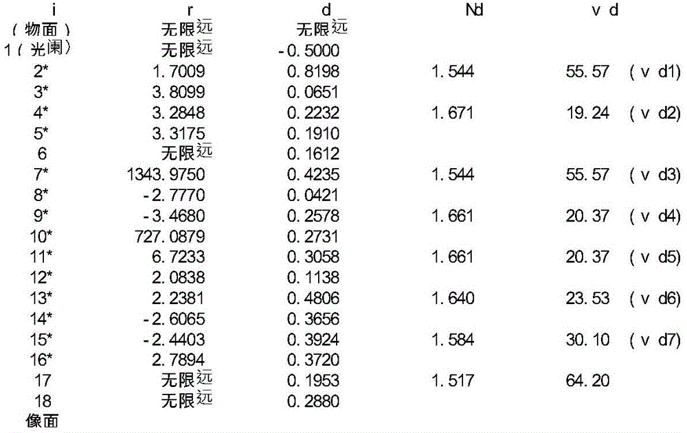
将基本的透镜数据示于以下的表1。Basic lens data are shown in Table 1 below.
[表1][Table 1]
实施例1Example 1
单位mmUnit mm
f=4.29f=4.29
Fno=1.68Fno=1.68
ω(°)=39.2ω(°)=39.2
ih=3.53ih=3.53
TTL=5.14TTL=5.14
面数据face data

组成透镜数据Composition lens data

非球面数据Aspheric data

实施例1的摄像镜头如表8所示,满足条件式(1)至(27)。As shown in Table 8, the imaging lens of Example 1 satisfies Conditional Expressions (1) to (27).
图2针对实施例1的摄像镜头,示出球面像差(mm)、像散(mm)、畸变(%)。球面像差图表示相对于F线(486nm)、d线(588nm)、C线(656nm)的各波长的像差量。并且,像散图中分别示出弧矢像面S上的d线的像差量(实线)、及子午像面T上的d线的像差量(虚线)(图4、图6、图8、图10、图12及图14中均相同)。如图2所示,可知各像差得到了良好的校正。FIG. 2 shows spherical aberration (mm), astigmatism (mm), and distortion (%) for the imaging lens of Example 1. FIG. The spherical aberration graph shows the amount of aberration at each wavelength with respect to the F line (486 nm), the d line (588 nm), and the C line (656 nm). In addition, the astigmatism diagrams show the aberration amount (solid line) of the d-line on the sagittal image plane S and the aberration amount (broken line) of the d-line on the meridional image plane T, respectively ( FIG. 4 , FIG. 6 , 8, 10, 12 and 14 are the same). As shown in FIG. 2 , it can be seen that each aberration is satisfactorily corrected.
[实施例2][Example 2]
将基本的透镜数据示于以下的表2。Basic lens data are shown in Table 2 below.
[表2][Table 2]
实施例2Example 2
单位mmUnit mm
f=4.25f=4.25
Fno=1.65Fno=1.65
ω(°)=39.2ω(°)=39.2
ih=3.53ih=3.53
TTL=5.15TTL=5.15
面数据face data

组成透镜数据Composition lens data

非球面数据Aspheric data

实施例2的摄像镜头如表8所示,满足条件式(1)至(27)。As shown in Table 8, the imaging lens of Example 2 satisfies Conditional Expressions (1) to (27).
图4针对实施例2的摄像镜头,示出球面像差(mm)、像散(mm)、畸变(%)。如图4所示,可知各像差得到了良好的校正。FIG. 4 shows spherical aberration (mm), astigmatism (mm), and distortion (%) for the imaging lens of Example 2. FIG. As shown in FIG. 4 , it can be seen that each aberration is satisfactorily corrected.
[实施例3][Example 3]
将基本的透镜数据示于以下的表3。Basic lens data are shown in Table 3 below.
[表3][table 3]
实施例3Example 3
单位mmUnit mm
f=4.13f=4.13
Fno=1.62Fno=1.62
ω(°)=38.0ω(°)=38.0
ih=3.28ih=3.28
TTL=5.21TTL=5.21
面数据face data

组成透镜数据Composition lens data

非球面数据Aspheric data

实施例3的摄像镜头如表8所示,满足条件式(1)至(27)。As shown in Table 8, the imaging lens of Example 3 satisfies Conditional Expressions (1) to (27).
图6针对实施例3的摄像镜头,示出球面像差(mm)、像散(mm)、畸变(%)。如图6所示,可知各像差得到了良好的校正。FIG. 6 shows spherical aberration (mm), astigmatism (mm), and distortion (%) for the imaging lens of Example 3. FIG. As shown in FIG. 6 , it can be seen that each aberration is satisfactorily corrected.
[实施例4][Example 4]
将基本的透镜数据示于以下的表4。Basic lens data are shown in Table 4 below.
[表4][Table 4]
实施例4Example 4
单位mmUnit mm
f=4.32f=4.32
Fno=1.68Fno=1.68
ω(°)=38.8ω(°)=38.8
ih=3.53ih=3.53
TTL=5.20TTL=5.20
面数据face data

组成透镜数据Composition lens data

非球面数据Aspheric data

实施例4的摄像镜头如表8所示,满足条件式(1)至(27)。As shown in Table 8, the imaging lens of Example 4 satisfies Conditional Expressions (1) to (27).
图8针对实施例4的摄像镜头,示出球面像差(mm)、像散(mm)、畸变(%)。如图8所示,可知各像差得到了良好的校正。FIG. 8 shows spherical aberration (mm), astigmatism (mm), and distortion (%) for the imaging lens of Example 4. FIG. As shown in FIG. 8 , it can be seen that each aberration is satisfactorily corrected.
[实施例5][Example 5]
将基本的透镜数据示于以下的表5。Basic lens data are shown in Table 5 below.
[表5][table 5]
实施例5Example 5
单位mmUnit mm
f=4.10f=4.10
Fno=1.71Fno=1.71
ω(°)=38.2ω(°)=38.2
ih=3.28ih=3.28
TTL=4.90TTL=4.90
面数据face data
组成透镜数据Composition lens data

非球面数据Aspheric data

实施例5的摄像镜头如表8所示,满足条件式(1)至(27)。As shown in Table 8, the imaging lens of Example 5 satisfies Conditional Expressions (1) to (27).
图10针对实施例5的摄像镜头,示出球面像差(mm)、像散(mm)、畸变(%)。如图10所示,可知各像差得到了良好的校正。FIG. 10 shows spherical aberration (mm), astigmatism (mm), and distortion (%) for the imaging lens of Example 5. FIG. As shown in FIG. 10 , it can be seen that each aberration is satisfactorily corrected.
[实施例6][Example 6]
将基本的透镜数据示于以下的表6。Basic lens data are shown in Table 6 below.
[表6][Table 6]
实施例6Example 6
单位mmUnit mm
f=4.33f=4.33
Fno=1.72Fno=1.72
ω(°)=38.7ω(°)=38.7
ih=3.53ih=3.53
TTL=5.24TTL=5.24
面数据face data

组成透镜数据Composition lens data

非球面数据Aspheric data

实施例6的摄像镜头如表8所示,满足条件式(1)至(27)。As shown in Table 8, the imaging lens of Example 6 satisfies Conditional Expressions (1) to (27).
图12针对实施例6的摄像镜头,示出球面像差(mm)、像散(mm)、畸变(%)。如图12所示,可知各像差得到了良好的校正。FIG. 12 shows spherical aberration (mm), astigmatism (mm), and distortion (%) for the imaging lens of Example 6. FIG. As shown in FIG. 12 , it can be seen that each aberration is satisfactorily corrected.
[实施例7][Example 7]
将基本的透镜数据示于以下的表7。Basic lens data are shown in Table 7 below.
[表7][Table 7]
实施例7Example 7
单位mmUnit mm
f=4.44f=4.44
Fno=1.46Fno=1.46
ω(°)=38.0ω(°)=38.0
ih=3.53ih=3.53
TTL=5.59TTL=5.59
面数据face data

组成透镜数据Composition lens data

非球面数据Aspheric data

实施例7的摄像镜头如表8所示,满足条件式(1)至(27)。As shown in Table 8, the imaging lens of Example 7 satisfies Conditional Expressions (1) to (27).
图14针对实施例7的摄像镜头,示出球面像差(mm)、像散(mm)、畸变(%)。如图14所示,可知各像差得到了良好的校正。FIG. 14 shows spherical aberration (mm), astigmatism (mm), and distortion (%) for the imaging lens of Example 7. FIG. As shown in FIG. 14 , it can be seen that each aberration is satisfactorily corrected.
表8示出实施例1至实施例7所涉及的条件式(1)至(27)的值。Table 8 shows the values of Conditional Expressions (1) to (27) related to Examples 1 to 7.
[表8][Table 8]

产业上的可利用性Industrial Availability
将本发明所涉及的摄像镜头应用于附设有相机功能的产品的情况下,能够有助于该相机的广角化、低背化以及低F值化,并且能够实现相机的高性能化。When the imaging lens according to the present invention is applied to a product with a camera function, it can contribute to widening the angle, low profile, and low F value of the camera, and can achieve high performance of the camera.
Claims (5)
Priority Applications (1)
| Application Number | Priority Date | Filing Date | Title |
|---|---|---|---|
| CN202110881286.9A CN113640948B (en) | 2018-10-23 | 2019-10-23 | Camera lens |
Applications Claiming Priority (2)
| Application Number | Priority Date | Filing Date | Title |
|---|---|---|---|
| JP2018199085A JP6821276B2 (en) | 2018-10-23 | 2018-10-23 | Imaging lens |
| JP2018-199085 | 2018-10-23 |
Related Child Applications (1)
| Application Number | Title | Priority Date | Filing Date |
|---|---|---|---|
| CN202110881286.9A Division CN113640948B (en) | 2018-10-23 | 2019-10-23 | Camera lens |
Publications (2)
| Publication Number | Publication Date |
|---|---|
| CN111090165A CN111090165A (en) | 2020-05-01 |
| CN111090165B true CN111090165B (en) | 2022-01-14 |
Family
ID=70390219
Family Applications (3)
| Application Number | Title | Priority Date | Filing Date |
|---|---|---|---|
| CN201911013389.2A Active CN111090165B (en) | 2018-10-23 | 2019-10-23 | Camera lens |
| CN202110881286.9A Active CN113640948B (en) | 2018-10-23 | 2019-10-23 | Camera lens |
| CN201921792575.6U Active CN211149035U (en) | 2018-10-23 | 2019-10-23 | Camera lens |
Family Applications After (2)
| Application Number | Title | Priority Date | Filing Date |
|---|---|---|---|
| CN202110881286.9A Active CN113640948B (en) | 2018-10-23 | 2019-10-23 | Camera lens |
| CN201921792575.6U Active CN211149035U (en) | 2018-10-23 | 2019-10-23 | Camera lens |
Country Status (3)
| Country | Link |
|---|---|
| US (2) | US11262546B2 (en) |
| JP (1) | JP6821276B2 (en) |
| CN (3) | CN111090165B (en) |
Families Citing this family (17)
| Publication number | Priority date | Publication date | Assignee | Title |
|---|---|---|---|---|
| CN109613679B (en) * | 2018-12-31 | 2021-09-28 | 诚瑞光学(常州)股份有限公司 | Image pickup optical lens |
| KR102270301B1 (en) * | 2019-06-17 | 2021-06-30 | 삼성전기주식회사 | Imaging Lens System |
| CN114578519A (en) * | 2019-08-21 | 2022-06-03 | 核心光电有限公司 | Lens assembly |
| CN110673307B (en) * | 2019-10-15 | 2022-05-24 | 玉晶光电(厦门)有限公司 | Optical imaging lens |
| JP7416636B2 (en) * | 2020-01-28 | 2024-01-17 | 東京晨美光学電子株式会社 | imaging lens |
| CN111458840B (en) * | 2020-04-26 | 2022-05-24 | 玉晶光电(厦门)有限公司 | Optical imaging lens |
| JP6919028B1 (en) * | 2020-06-23 | 2021-08-11 | エーエーシー オプティックス ソリューションズ ピーティーイー リミテッド | Imaging lens |
| CN111736301B (en) * | 2020-06-24 | 2025-05-09 | 江西欧菲光学有限公司 | Optical systems, imaging modules and electronic equipment |
| CN111897098B (en) * | 2020-08-27 | 2025-07-08 | 江西欧菲光学有限公司 | Optical system, camera module and electronic equipment |
| CN114167576B (en) * | 2020-09-11 | 2023-03-28 | 新巨科技股份有限公司 | Seven-piece imaging lens set |
| CN113064263B (en) * | 2021-04-30 | 2025-05-16 | 厦门力鼎光电股份有限公司 | An optical imaging lens |
| KR102921405B1 (en) | 2021-07-05 | 2026-02-02 | 삼성전기주식회사 | Imaging Lens System |
| CN114740596B (en) * | 2022-03-22 | 2023-09-05 | 江西晶超光学有限公司 | Optical system, image capturing module and electronic equipment |
| KR102827672B1 (en) * | 2022-05-31 | 2025-07-02 | 삼성전기주식회사 | Optical Imaging System |
| CN116661098B (en) * | 2023-05-12 | 2025-08-29 | 浙江舜宇光学有限公司 | Camera lens |
| CN117930470B (en) * | 2024-03-22 | 2024-06-11 | 江西联益光学有限公司 | Optical lens |
| KR20250154024A (en) * | 2024-04-19 | 2025-10-28 | 엘지이노텍 주식회사 | Optical system and camera module |
Citations (2)
| Publication number | Priority date | Publication date | Assignee | Title |
|---|---|---|---|---|
| JP2012155223A (en) * | 2011-01-27 | 2012-08-16 | Tamron Co Ltd | Wide-angle single-focus lens |
| CN107966785A (en) * | 2016-10-19 | 2018-04-27 | 康达智株式会社 | camera lens |
Family Cites Families (9)
| Publication number | Priority date | Publication date | Assignee | Title |
|---|---|---|---|---|
| TWI570467B (en) * | 2012-07-06 | 2017-02-11 | 大立光電股份有限公司 | Optical image pickup system group |
| KR101580382B1 (en) * | 2013-10-14 | 2015-12-24 | 삼성전기주식회사 | Lens module |
| KR101719878B1 (en) * | 2014-12-10 | 2017-03-24 | 삼성전기주식회사 | Lens module |
| CN108710193B (en) * | 2015-02-17 | 2020-09-01 | 大立光电股份有限公司 | Camera system and imaging device |
| JP6478903B2 (en) * | 2015-12-21 | 2019-03-06 | カンタツ株式会社 | Imaging lens |
| TWI595261B (en) | 2016-02-04 | 2017-08-11 | 大立光電股份有限公司 | Optical lens group for imaging, image capturing device, and electronic device |
| WO2019080554A1 (en) * | 2017-10-26 | 2019-05-02 | 浙江舜宇光学有限公司 | Optical imaging lens |
| US10558017B2 (en) * | 2018-04-26 | 2020-02-11 | AAC Technologies Pte. Ltd. | Camera optical lens |
| TWI675221B (en) * | 2018-06-06 | 2019-10-21 | 大立光電股份有限公司 | Photographing optical lens assembly, imaging apparatus and electronic device |
-
2018
- 2018-10-23 JP JP2018199085A patent/JP6821276B2/en active Active
-
2019
- 2019-10-22 US US16/660,306 patent/US11262546B2/en not_active Expired - Fee Related
- 2019-10-23 CN CN201911013389.2A patent/CN111090165B/en active Active
- 2019-10-23 CN CN202110881286.9A patent/CN113640948B/en active Active
- 2019-10-23 CN CN201921792575.6U patent/CN211149035U/en active Active
-
2021
- 2021-08-02 US US17/391,852 patent/US12007535B2/en active Active
Patent Citations (2)
| Publication number | Priority date | Publication date | Assignee | Title |
|---|---|---|---|---|
| JP2012155223A (en) * | 2011-01-27 | 2012-08-16 | Tamron Co Ltd | Wide-angle single-focus lens |
| CN107966785A (en) * | 2016-10-19 | 2018-04-27 | 康达智株式会社 | camera lens |
Also Published As
| Publication number | Publication date |
|---|---|
| CN113640948B (en) | 2022-12-27 |
| US12007535B2 (en) | 2024-06-11 |
| JP6821276B2 (en) | 2021-01-27 |
| US20210364763A1 (en) | 2021-11-25 |
| US11262546B2 (en) | 2022-03-01 |
| JP2020067525A (en) | 2020-04-30 |
| CN113640948A (en) | 2021-11-12 |
| US20210033821A1 (en) | 2021-02-04 |
| CN211149035U (en) | 2020-07-31 |
| CN111090165A (en) | 2020-05-01 |
Similar Documents
| Publication | Publication Date | Title |
|---|---|---|
| CN111090165B (en) | Camera lens | |
| CN212031835U (en) | Camera lens | |
| CN211928289U (en) | Camera lens | |
| CN108983390B (en) | camera lens | |
| CN111061034B (en) | Camera lens | |
| CN108931844B (en) | camera lens | |
| CN109387927B (en) | camera lens | |
| CN108008519B (en) | camera lens | |
| CN109960015B (en) | Camera lens | |
| CN210123495U (en) | Camera lens | |
| CN110850550A (en) | camera lens | |
| CN106054354B (en) | camera lens | |
| CN111929809A (en) | Camera lens | |
| CN112394479B (en) | Image pickup lens | |
| CN109387928B (en) | camera lens | |
| CN110727080B (en) | camera lens | |
| CN210348040U (en) | camera lens | |
| CN112799210A (en) | camera lens | |
| CN216310375U (en) | Camera lens | |
| CN113741002A (en) | Camera lens | |
| CN114077039A (en) | Camera lens | |
| CN112068283A (en) | Camera lens | |
| CN113946032A (en) | Camera lens | |
| CN212009118U (en) | Camera lens | |
| CN114815140A (en) | Camera lens |
Legal Events
| Date | Code | Title | Description |
|---|---|---|---|
| PB01 | Publication | ||
| PB01 | Publication | ||
| SE01 | Entry into force of request for substantive examination | ||
| SE01 | Entry into force of request for substantive examination | ||
| TA01 | Transfer of patent application right |
Effective date of registration: 20210813 Address after: Tokyo Applicant after: Tokyo chenmei Optical Electronics Co.,Ltd. Address before: Japan Tochigi Applicant before: Kangdazhi Corp. |
|
| TA01 | Transfer of patent application right | ||
| GR01 | Patent grant | ||
| GR01 | Patent grant |