CN106054354B - camera lens - Google Patents
camera lens Download PDFInfo
- Publication number
- CN106054354B CN106054354B CN201610228874.1A CN201610228874A CN106054354B CN 106054354 B CN106054354 B CN 106054354B CN 201610228874 A CN201610228874 A CN 201610228874A CN 106054354 B CN106054354 B CN 106054354B
- Authority
- CN
- China
- Prior art keywords
- lens
- image
- refractive power
- imaging
- imaging lens
- Prior art date
- Legal status (The legal status is an assumption and is not a legal conclusion. Google has not performed a legal analysis and makes no representation as to the accuracy of the status listed.)
- Expired - Fee Related
Links
Images


Classifications
-
- G—PHYSICS
- G02—OPTICS
- G02B—OPTICAL ELEMENTS, SYSTEMS OR APPARATUS
- G02B9/00—Optical objectives characterised both by the number of the components and their arrangements according to their sign, i.e. + or -
- G02B9/60—Optical objectives characterised both by the number of the components and their arrangements according to their sign, i.e. + or - having five components only
-
- G—PHYSICS
- G02—OPTICS
- G02B—OPTICAL ELEMENTS, SYSTEMS OR APPARATUS
- G02B13/00—Optical objectives specially designed for the purposes specified below
- G02B13/001—Miniaturised objectives for electronic devices, e.g. portable telephones, webcams, PDAs, small digital cameras
- G02B13/0015—Miniaturised objectives for electronic devices, e.g. portable telephones, webcams, PDAs, small digital cameras characterised by the lens design
- G02B13/002—Miniaturised objectives for electronic devices, e.g. portable telephones, webcams, PDAs, small digital cameras characterised by the lens design having at least one aspherical surface
- G02B13/0045—Miniaturised objectives for electronic devices, e.g. portable telephones, webcams, PDAs, small digital cameras characterised by the lens design having at least one aspherical surface having five or more lenses
-
- G—PHYSICS
- G02—OPTICS
- G02B—OPTICAL ELEMENTS, SYSTEMS OR APPARATUS
- G02B13/00—Optical objectives specially designed for the purposes specified below
- G02B13/06—Panoramic objectives; So-called "sky lenses" including panoramic objectives having reflecting surfaces
-
- G—PHYSICS
- G02—OPTICS
- G02B—OPTICAL ELEMENTS, SYSTEMS OR APPARATUS
- G02B13/00—Optical objectives specially designed for the purposes specified below
- G02B13/18—Optical objectives specially designed for the purposes specified below with lenses having one or more non-spherical faces, e.g. for reducing geometrical aberration
Landscapes
- Physics & Mathematics (AREA)
- General Physics & Mathematics (AREA)
- Optics & Photonics (AREA)
- Lenses (AREA)
Abstract
一种摄像镜头,其从物体侧依次由凸面朝向物体侧的正的第1透镜、凸面朝向物体侧的负的第2透镜、第3透镜、正的第4透镜以及凹面朝向像侧的双面为非球面的负的第5透镜构成,并满足如下条件:Fno≤2.4、TTL/2ih<0.9、f45<0、0<r5/r6<4.0、0.5<(r7+r8)/(r7‑r8)<3.0、0.4<(r9+r10)/(r9‑r10)<4.0。通过本发明的摄像镜头能够获得适应低背、低F值及拍摄视场角的广角化的要求,且具备各像差得到良好校正的高分辨率的小型摄像镜头。

An imaging lens comprising, in order from the object side, a positive first lens with a convex surface facing the object side, a negative second lens with a convex surface facing the object side, a third lens, a positive fourth lens, and a double surface with a concave surface facing the image side It is composed of an aspherical negative fifth lens and satisfies the following conditions: Fno≤2.4, TTL/2ih<0.9, f45<0, 0<r5/r6<4.0, 0.5<(r7+r8)/(r7‑r8 )<3.0, 0.4<(r9+r10)/(r9‑r10)<4.0. According to the imaging lens of the present invention, it is possible to obtain a small imaging lens with high resolution, which can meet the requirements of low back, low F value, and widening of the shooting angle of view, and has well-corrected various aberrations.
Description
技术领域technical field
本发明涉及一种在使用于小型摄像装置中的CCD传感器或C-MOS传感器的固体摄像元件上形成被摄体的像的摄像镜头,尤其涉及一种趋向小型化、低背化的智能手机和移动电话及PDA(Personal Digital Assistant)和游戏机、PC等信息终端设备等、以及搭载于附带相机功能的家电产品和汽车等上的摄像装置中的摄像镜头。The present invention relates to an imaging lens for forming an image of a subject on a solid-state imaging element of a CCD sensor or a C-MOS sensor used in a small imaging device, and in particular to a smart phone that tends to be miniaturized and low-backed. Mobile phones, PDAs (Personal Digital Assistants), game consoles, PCs, and other information terminal equipment, etc., as well as imaging lenses installed in imaging devices such as home appliances with camera functions and automobiles.
背景技术Background technique
近年来,很多信息终端设备都普遍搭载相机功能。并且,有越来越多的附带相机的家电产品等极其方便的产品问世,在这种家电产品和信息终端设备上结合了相机功能的产品需求也逐日剧增,因此预计会急速推进相应产品的开发。In recent years, many information terminal devices are equipped with camera functions. In addition, there are more and more convenient products such as home appliances with cameras coming out, and the demand for products incorporating camera functions in such home appliances and information terminal equipment is also increasing day by day, so it is expected that the corresponding products will be rapidly promoted development.
并且,不仅要求搭载于这些产品上的摄像镜头具备应对高像素化的高分辨率,而且要求其为能够充分应对设备的超薄化的小型及低背的摄像镜头,而且为明亮的镜头系统,此外还严格要求应对宽视场角。In addition, the imaging lenses mounted on these products are required not only to have high resolution to cope with high pixelation, but also to be small and low-profile imaging lenses that can sufficiently cope with the ultra-thinning of devices, as well as bright lens systems. In addition, it is also strictly required to deal with a wide field of view.
然而,若要实现满足低背、低F值、拍摄视场角的广角化的所有要求的摄像镜头,周边部的像差校正尤为困难,因此存在确保整个画面的良好光学性能的课题。However, in order to realize an imaging lens that satisfies all the requirements of low profile, low F value, and widening of the shooting angle of view, it is particularly difficult to correct aberrations in the peripheral portion, so there is a problem of ensuring good optical performance of the entire screen.
在现有技术中,作为小型且具备高分辨率的摄像镜头,例如已知有以下专利文献1和专利文献2中的摄像镜头。Conventionally, as a small imaging lens with high resolution, for example, the imaging lenses in the following
在专利文献1中公开有如下摄像镜头,该镜头从物体侧依次由具有正的折光力的第1透镜、凹面朝向物体侧的具有负的折光力的弯月形形状的第2透镜、具有正的折光力的第3透镜、在光轴附近凹面朝向物体侧的具有正的折光力的弯月形形状的第4透镜以及在光轴附近具有负的折光力且在周边部具有正的折光力的第5透镜构成。
专利文献2中公开有如下摄像镜头,该镜头从物体侧依次具备具有正的折光力的第1透镜、具有负的折光力的第2透镜、像侧的面为凸形状且具有正的折光力的第3透镜、凸面朝向像侧的弯月形形状的第4透镜及随着从中心朝向周边部负的折光力逐渐变弱且在周边部具有正的折光力的第5透镜。
专利文献1:日本特开2011-257447号公报Patent Document 1: Japanese Patent Laid-Open No. 2011-257447
专利文献2:日本特开2011-141396号公报Patent Document 2: Japanese Patent Laid-Open No. 2011-141396
上述专利文献1中记载的摄像镜头的明亮度为F1.9左右,光学全长与摄像元件的有效摄像面的对角线的长度之比(以下,称为全长对角比)大约为1.0,而且高度比较低且各像差得到良好的校正。但是,拍摄视场角大约为65°,因此只能应对以前要求的水平。若要在维持F值与全长对角比的基础上进一步实现广角化,出于要求具有相对较强的光学系统中的正的折光力这一点,难以实现各透镜的折光力平衡,且轴上色像差和周边部的各像差的校正会受到局限。The imaging lens disclosed in
上述专利文献2中记载的摄像镜头的明亮度也在F2.0左右,且全长对角比为1.0左右,在高低比较低的基础上确保了良好的光学性能。但是,拍摄视场角只能应对大约60°左右。上述专利文献2中记载的摄像镜头中也同样,在维持F值与全长对角比及光学性能的基础上无法应对如超过70°的视场角。The imaging lens described in the above-mentioned
发明内容SUMMARY OF THE INVENTION
本发明是鉴于上述课题而完成的,其目的在于提供一种不仅能够均衡地满足低背、低F值、拍摄视场角的广角化的要求且具备各像差得到良好校正的高分辨率的小型摄像镜头。The present invention has been made in view of the above-mentioned problems, and an object of the present invention is to provide a high-resolution camera that not only satisfies the requirements of low back, low F value, and widening of the shooting angle of view in a balanced manner, but also has good correction of various aberrations. Small camera lens.
另外,在此所谓低背是指,光学全长小于5mm,远摄比小于1.2,且全长对角比小于0.9的水平,低F值是指F2.4以下的明亮度,广角是指能够在全视场角70°以上的范围内进行拍摄的水平。另外,表示全长对角比时的摄像元件的有效摄像面的对角线的长度为从最大视场角入射到摄像镜头的光线在摄像面成像时的自光轴的垂直高度即最大像高的2倍长度,视为与有效摄像圆的直径相同。In addition, the low-back here refers to the level where the overall optical length is less than 5mm, the telephoto ratio is less than 1.2, and the full-length-to-diagonal ratio is less than 0.9. The level of shooting within the range of 70° or more of the full field of view. In addition, the length of the diagonal line of the effective imaging surface of the imaging element at the time of the full-length-to-diagonal ratio is the vertical height from the optical axis when the light rays incident on the imaging lens from the maximum angle of view are formed on the imaging surface, that is, the maximum image height. is twice as long as the diameter of the effective imaging circle.
并且,关于在本发明中使用的术语,透镜面的凸面、凹面被定义为近轴(光轴附近)的形状,极点被定义为切平面与光轴垂直相交且不在光轴上的非球面上的点。此外,光学全长被定义为,利用空气换算IR截止滤光片和保护玻璃等不影响光的发散及收敛的光学元件的厚度时,从离被摄体最近的光学元件的物体侧的面至像面为止的光轴上的距离。Also, regarding the terms used in the present invention, the convex and concave surfaces of the lens surface are defined as the shape of the paraxial (near the optical axis), and the pole is defined as the aspheric surface where the tangent plane perpendicularly intersects the optical axis and is not on the optical axis. point. In addition, the total optical length is defined as the thickness from the object-side surface of the optical element closest to the subject to The distance on the optical axis to the image plane.
本发明的摄像镜头,在固体摄像元件上形成被摄体的像,该镜头从物体侧朝向像侧依次由凸面朝向物体侧的具有正的折光力的第1透镜、凸面朝向物体侧的具有负的折光力的第2透镜、具有正的折光力或负的折光力的第3透镜、具有正的折光力的第4透镜、凹面朝向像侧的具有负的折光力的双面为非球面的第5透镜构成,该摄像镜头满足以下条件式(1)至(6b)、(10b)、(12):The imaging lens of the present invention forms an image of a subject on a solid-state imaging element, and the lens includes a first lens having a positive refractive power with a convex surface facing the object side, and a negative lens having a convex surface facing the object side in this order from the object side toward the image side. A second lens with a high refractive power, a third lens with a positive refractive power or a negative refractive power, a fourth lens with a positive refractive power, and a concave surface facing the image side with a negative refractive power. Both sides are aspherical The fifth lens consists of the imaging lens satisfying the following Conditional Expressions (1) to (6b), (10b), and (12):
(1)Fno≤2.4(1) Fno≤2.4
(2b)TTL/2ih<0.83(2b)TTL/2ih<0.83
(3)f45<0(3) f45<0
(4)0<r5/r6<4.0(4) 0<r5/r6<4.0
(5a)0.5<(r7+r8)/(r7-r8)<2.0(5a)0.5<(r7+r8)/(r7-r8)<2.0
(6b)0.58≤(r9+r10)/(r9-r10)≤1.5(6b)0.58≤(r9+r10)/(r9-r10)≤1.5
(10b)0.10≤T3/TTL≤0.13(10b)0.10≤T3/TTL≤0.13
(12)1.5<r3/r4<50(12) 1.5<r3/r4<50
其中,Fno为F值,ih为最大像高,TTL为光学全长,f45为第4透镜与第5透镜的合成焦距,r5为第3透镜的物体侧的面的曲率半径,r6为第3透镜的像侧的面的曲率半径,r7为第4透镜的物体侧的面的曲率半径,r8为第4透镜的像侧的面的曲率半径,r9为第5透镜的物体侧的面的曲率半径,r10为第5透镜的像侧的面的曲率半径,T3为第3透镜的像侧的面与第4透镜的物体侧的面的光轴上的距离,r3为第2透镜的物体侧的面的曲率半径,r4为第2透镜的像侧的面的曲率半径。where Fno is the F value, ih is the maximum image height, TTL is the total optical length, f45 is the combined focal length of the fourth lens and the fifth lens, r5 is the radius of curvature of the object-side surface of the third lens, and r6 is the third lens The curvature radius of the image side surface of the lens, r7 is the curvature radius of the object side surface of the fourth lens, r8 is the curvature radius of the fourth lens image side surface, and r9 is the curvature radius of the fifth lens object side surface Radius, r10 is the radius of curvature of the image-side surface of the fifth lens, T3 is the distance on the optical axis between the image-side surface of the third lens and the object-side surface of the fourth lens, and r3 is the object-side surface of the second lens is the radius of curvature of the surface of the second lens, and r4 is the radius of curvature of the surface of the second lens on the image side.
本发明的摄像镜头为从物体侧依次配置有由第1透镜、第2透镜及第3透镜构成的合成折光力为正的透镜组以及由第4透镜和第5透镜构成的合成折光力为负的透镜组的所谓远摄类型。并且,通过将远摄比设为1.20以下来将光学全长抑制得较短,且实现低背化。In the imaging lens of the present invention, a lens group composed of a first lens, a second lens, and a third lens having a positive composite refractive power and a fourth lens and a fifth lens having a negative composite refractive power are arranged in this order from the object side. The so-called telephoto type of lens group. In addition, by setting the telephoto ratio to be 1.20 or less, the overall optical length is suppressed to be short, and a low profile is achieved.
在上述结构中,由第1透镜、第2透镜及第3透镜构成的正透镜组来负责进行摄像镜头的低背化、广角化及色像差的良好校正。通过将第1透镜设为凸面朝向物体侧的具有正的折光力的透镜,使其通过较强的正的折光力实现摄像镜头的低背化与广角化。通过将第2透镜设为凸面朝向物体侧的具有负的折光力的透镜,使其良好地校正在第1透镜中产生的球面像差及色像差。通过将第3透镜设为在构成摄像镜头的透镜中折光力最弱的透镜,使其主要校正高次球面像差、彗差及像散。In the above configuration, the positive lens group consisting of the first lens, the second lens, and the third lens is responsible for the low-back, wide-angle, and excellent correction of chromatic aberration of the imaging lens. By making the first lens a lens having a positive refractive power with a convex surface facing the object side, a low profile and wide angle of the imaging lens can be achieved by having a strong positive refractive power. The spherical aberration and chromatic aberration occurring in the first lens can be corrected favorably by making the second lens a lens having a negative refractive power with a convex surface facing the object side. By making the third lens the lens with the weakest refractive power among the lenses constituting the imaging lens, it mainly corrects high-order spherical aberration, coma aberration, and astigmatism.
由第4透镜和第5透镜构成的负透镜组负责摄像镜头的低背化、广角化及各像差的良好校正。具有较强的正的折光力的第4透镜通过与第1透镜的正的折光力适当平衡,不仅实现摄像镜头的低背化与广角化,还良好地校正像散及场曲。并且,通过将第5透镜设为以凹面作为像侧的面的具有负的折光力的双面非球面的透镜,使其有效地进行在第4透镜中产生的球面像差及色像差的校正、场曲的校正及入射到摄像元件的主光线入射角度的控制。The negative lens group consisting of the fourth lens and the fifth lens is responsible for the low profile and wide angle of the imaging lens, as well as good correction of various aberrations. The fourth lens having a strong positive refractive power is properly balanced with the positive refractive power of the first lens, so that not only a low profile and wide angle of the imaging lens can be achieved, but also astigmatism and field curvature can be corrected well. In addition, by making the fifth lens a double-sided aspherical lens with negative refractive power and having a concave surface as the image side surface, spherical aberration and chromatic aberration occurring in the fourth lens can be effectively eliminated. Correction, correction of field curvature, and control of the incident angle of the chief ray incident on the imaging element.
条件式(1)为用于适当地设定镜头的明亮度的条件。当超过条件式(1)的上限值时,对于小型且高像素的摄像元件的明亮度不够充足,且可能有损图像的鲜明度,因此不优选。Conditional expression (1) is a condition for appropriately setting the brightness of the lens. When the upper limit value of the conditional expression (1) is exceeded, the brightness is insufficient for a small and high-pixel imaging element, and the sharpness of the image may be impaired, which is not preferable.
条件式(2)規定全长对角比。当超过条件式(2)的上限值时,光学全长变得过长,因此难以应对低背化的要求。Conditional expression (2) specifies the full-length-to-diagonal ratio. When the upper limit value of the conditional expression (2) is exceeded, the total optical length becomes too long, and thus it becomes difficult to meet the demand for low profile.
条件式(3)規定第4透镜与第5透镜的合成折光力,且表示第4透镜与第5透镜的合成折光力为负。通过配置于物体侧的由3片构成的正透镜组和配置于像侧的由2片构成的负透镜组,提高远摄性,且能够适当地缩短光学全长。Conditional expression (3) defines the combined refractive power of the fourth lens and the fifth lens, and indicates that the combined refractive power of the fourth lens and the fifth lens is negative. By the positive lens group consisting of three lenses arranged on the object side and the negative lens group consisting of two lenses arranged on the image side, the telephoto performance can be improved, and the total optical length can be shortened appropriately.
条件式(4)規定近轴上的第3透镜的形状,且为用于抑制像散的产生的条件。通过满足条件式(4),第3透镜在光轴附近成为弯月形形状,因此能够适当地校正像散。Conditional expression (4) defines the shape of the third lens on the paraxial axis, and is a condition for suppressing the occurrence of astigmatism. By satisfying the conditional expression (4), the third lens has a meniscus shape in the vicinity of the optical axis, so astigmatism can be appropriately corrected.
条件式(5)規定近轴上的第4透镜的形状,且为用于实现摄像镜头的低背化且校正各像差的条件。当超过条件式(5)的上限值时,第4透镜的像侧的面的折光力变得过强,而难以校正场曲等的高次像差。另一方面,当小于条件式(5)的下限值时,第4透镜的像侧的面的折光力变弱,因此难以缩短光学全长。通过满足条件式(5)的范围,不仅能够充分抑制第4透镜的像侧的面的折光力,还能够一并进行摄像镜头的低背化、场曲及像散等高次像差的校正。Conditional expression (5) defines the shape of the fourth lens on the paraxial axis, and is a condition for realizing a low profile of the imaging lens and correcting various aberrations. When the upper limit value of the conditional expression (5) is exceeded, the refractive power of the image-side surface of the fourth lens becomes too strong, making it difficult to correct higher-order aberrations such as field curvature. On the other hand, if it is less than the lower limit of the conditional expression (5), since the refractive power of the image-side surface of the fourth lens becomes weak, it becomes difficult to shorten the total optical length. By satisfying the range of Conditional Expression (5), not only can the refractive power of the image-side surface of the fourth lens be sufficiently suppressed, but also higher-order aberrations such as field curvature and astigmatism can be corrected simultaneously with the image pickup lens. .
条件式(6)規定近轴上的第5透镜的形状,且为用于良好地校正各像差的条件。当超过条件式(6)的上限值时,第5透镜的像侧的面的曲率半径变得过强,且光线发散过度,因此难以校正场曲。另一方面,当小于条件式(6)的下限值时,第5透镜的物体侧的面的折光力变得过强,而难以校正球面像差及场曲。Conditional expression (6) defines the shape of the fifth lens on the paraxial axis, and is a condition for favorably correcting each aberration. If the upper limit value of the conditional expression (6) is exceeded, the curvature radius of the image-side surface of the fifth lens becomes too strong, and the light rays diverge too much, making it difficult to correct the curvature of field. On the other hand, if it is less than the lower limit of the conditional expression (6), the refractive power of the object-side surface of the fifth lens becomes too strong, making it difficult to correct spherical aberration and field curvature.
并且,在本发明的摄像镜头中,优选满足以下条件式(7):Furthermore, in the imaging lens of the present invention, it is preferable to satisfy the following conditional formula (7):
(7)3.0<|f3/f|(7)3.0<|f3/f|
其中,f为整个摄像镜头系统的焦距,f3为第3透镜的焦距。Among them, f is the focal length of the entire camera lens system, and f3 is the focal length of the third lens.
条件式(7)将第3透镜的焦距相对于整个摄像镜头系统的焦距之比規定在适当的范围内。第3透镜的折光力被设定为在构成摄像镜头的5片透镜中最弱的折光力,且抑制其影响整个摄像镜头系统的折光力和其他各透镜的折光力。由此,抑制在轴上产生像差,且能够良好地校正场曲和畸变。Conditional expression (7) defines the ratio of the focal length of the third lens to the focal length of the entire imaging lens system within an appropriate range. The refractive power of the third lens is set to be the weakest refractive power among the five lenses constituting the imaging lens, and is suppressed from affecting the refractive power of the entire imaging lens system and the refractive power of each other lens. Thereby, generation of aberration on the axis is suppressed, and field curvature and distortion can be corrected favorably.
并且,在本发明的摄像镜头中,优选满足以下条件式(8):Furthermore, in the imaging lens of the present invention, it is preferable to satisfy the following Conditional Expression (8):
(8)0.4<f4/f<1.5(8) 0.4<f4/f<1.5
其中,f为整个摄像镜头系统的焦距,f4为第4透镜的焦距。Among them, f is the focal length of the entire camera lens system, and f4 is the focal length of the fourth lens.
条件式(8)将第4透镜的焦距相对于整个摄像镜头系统的焦距之比規定在适当的范围内,且为用于实现摄像镜头的低背化且良好地校正各像差的条件。当超过条件式(8)的上限值时,第4透镜的折光力变得过弱,而难以缩短光学全长。另一方面,当小于条件式(8)的下限值时,第4透镜的折光力变得过强,而使球面像差和彗差增大,且难以获得良好的光学性能。Conditional expression (8) defines the ratio of the focal length of the fourth lens to the focal length of the entire imaging lens system within an appropriate range, and is a condition for realizing a low profile of the imaging lens and satisfactorily correcting various aberrations. When the upper limit value of the conditional expression (8) is exceeded, the refractive power of the fourth lens becomes too weak, and it becomes difficult to shorten the total optical length. On the other hand, if it is less than the lower limit value of the conditional expression (8), the refractive power of the fourth lens becomes too strong, and spherical aberration and coma aberration increase, making it difficult to obtain good optical performance.
并且,在本发明的摄像镜头中,优选满足以下条件式(9):Furthermore, in the imaging lens of the present invention, it is preferable to satisfy the following Conditional Formula (9):
(9)-1.2<f5/f<-0.2(9)-1.2<f5/f<-0.2
其中,f为整个摄像镜头系统的焦距,f5为第5透镜的焦距。Among them, f is the focal length of the entire camera lens system, and f5 is the focal length of the fifth lens.
条件式(9)将第5透镜的焦距相对于整个摄像镜头系统的焦距之比規定在适当的范围内,且为用于缩短光学全长且良好地校正像差的条件。当超过条件式(9)的上限值时,第5透镜的负的折光力变得过强,而难以校正周边部的彗差、畸变及场曲。并且,由于后焦距变长,因此导致光学全长变长。另一方面,当小于条件式(9)的下限值时,第5透镜的折光力变得过弱,这虽然有利于缩短光学全长,但难以校正在第4透镜中产生的球面像差及色像差。Conditional expression (9) defines the ratio of the focal length of the fifth lens to the focal length of the entire imaging lens system within an appropriate range, and is a condition for shortening the total optical length and correcting aberrations well. When the upper limit value of the conditional expression (9) is exceeded, the negative refractive power of the fifth lens becomes too strong, and it becomes difficult to correct the coma aberration, distortion, and field curvature in the peripheral portion. In addition, since the back focal length becomes longer, the total optical length becomes longer. On the other hand, if the lower limit value of the conditional expression (9) is smaller than the lower limit value of the conditional expression (9), the refractive power of the fifth lens becomes too weak, which is beneficial to shorten the total optical length, but it is difficult to correct the spherical aberration generated in the fourth lens and chromatic aberration.
并且,在本发明的摄像镜头中,优选满足以下条件式(10):Furthermore, in the imaging lens of the present invention, it is preferable to satisfy the following conditional expression (10):
(10)0.08<T3/TTL<0.16(10) 0.08<T3/TTL<0.16
其中,T3为第3透镜的像侧的面与第4透镜的物体侧的面的光轴上的距离,TTL为光学全长。Here, T3 is the distance on the optical axis between the image-side surface of the third lens and the object-side surface of the fourth lens, and TTL is the total optical length.
条件式(10)为用于将第3透镜与第4透镜的空气间隔規定在适当的范围内的条件。当超过条件式(10)的上限值时,第3透镜与第4透镜的空气间隔变得过宽,而很难将光学全长抑制得较短。另一方面,当小于条件式(10)的下限值时,第3透镜与第4透镜的空气间隔变得过窄,因此会使这些透镜的形状受局限,其结果很难进行像差校正。Conditional expression (10) is a condition for regulating the air gap between the third lens and the fourth lens within an appropriate range. When the upper limit value of the conditional expression (10) is exceeded, the air gap between the third lens and the fourth lens becomes too wide, and it becomes difficult to keep the total optical length short. On the other hand, if it is less than the lower limit of the conditional expression (10), the air gap between the third lens and the fourth lens becomes too narrow, so that the shapes of these lenses are restricted, and as a result, it is difficult to perform aberration correction. .
并且,在本发明的摄像镜头中,优选满足以下条件式(11):Furthermore, in the imaging lens of the present invention, it is preferable to satisfy the following Conditional Expression (11):
(11)0.5<f1/f<2.0(11) 0.5<f1/f<2.0
其中,f为整个摄像镜头系统的焦距,f1为第1透镜的焦距。Among them, f is the focal length of the entire camera lens system, and f1 is the focal length of the first lens.
条件式(11)将第1透镜的焦距相对于整个摄像镜头系统的焦距之比規定在适当的范围内,且为用于抑制球面像差的产生且实现低背化与广角化的条件。当超过条件式(11)的上限值时,第1透镜的正的折光力变得过弱,这虽然有利于抑制球面像差的产生量,但难以实现摄像镜头的低背化与广角化。另一方面,当小于条件式(11)的下限值时,第1透镜的正的折光力变得过强,这虽然有利于摄像镜头的低背化与广角化,但会增大球面像差。Conditional expression (11) defines the ratio of the focal length of the first lens to the focal length of the entire imaging lens system within an appropriate range, and is a condition for suppressing the occurrence of spherical aberration and achieving low profile and wide angle. When the upper limit of the conditional expression (11) is exceeded, the positive refractive power of the first lens becomes too weak, which is beneficial to suppress the amount of spherical aberration, but it is difficult to achieve a low-back and wide-angle imaging lens . On the other hand, if it is less than the lower limit value of the conditional expression (11), the positive refractive power of the first lens becomes too strong, which is beneficial to the low-back and wide-angle imaging lens, but increases the spherical image. Difference.
并且,在本发明的摄像镜头中,优选满足以下条件式(12):Furthermore, in the imaging lens of the present invention, it is preferable to satisfy the following Conditional Expression (12):
(12)1.5<r3/r4<50(12) 1.5<r3/r4<50
其中,r3为第2透镜的物体侧的面的曲率半径,r4为第2透镜的像侧的面的曲率半径。Here, r3 is the radius of curvature of the surface of the second lens on the object side, and r4 is the radius of curvature of the surface of the second lens on the image side.
条件式(12)規定第2透镜的近轴上的形状,且为用于良好地校正各像差的条件。通过在条件式(12)的范围内增大第2透镜的像侧的面的折光力,不仅校正在第1透镜中产生的色像差,还良好地校正彗差、场曲及像散。Conditional expression (12) defines the paraxial shape of the second lens, and is a condition for favorably correcting each aberration. By increasing the refractive power of the image-side surface of the second lens within the range of Conditional Expression (12), not only the chromatic aberration generated in the first lens but also coma, field curvature, and astigmatism can be favorably corrected.
并且,在本发明的摄像镜头中,第4透镜优选为凸面朝向像侧的形状。Furthermore, in the imaging lens of the present invention, the fourth lens preferably has a shape in which a convex surface faces the image side.
通过将第4透镜的像侧的面形成为凸面,能够减小从该面射出的光线的出射角。由此,很容易进行随着光学全长的缩短化而增大的畸变、倍率色像差及像散的校正,且能够确保良好的光学性能。By forming the image-side surface of the fourth lens to be a convex surface, it is possible to reduce the exit angle of the light rays emitted from the surface. As a result, it is easy to correct the distortion, lateral chromatic aberration, and astigmatism that increase with the shortening of the total optical length, and it is possible to ensure good optical performance.
并且,在本发明的摄像镜头中,优选在第5透镜的像侧的面上在光轴上以外的位置形成有极点。Furthermore, in the imaging lens of the present invention, it is preferable that a pole is formed at a position other than the optical axis on the image-side surface of the fifth lens.
通过在第5透镜的像侧的面上在光轴上以外的位置形成极点,能够更有效地进行畸变及场曲的校正及入射到摄像元件的主光线的入射角度的控制。By forming a pole at a position other than the optical axis on the image-side surface of the fifth lens, it is possible to more effectively perform correction of distortion and field curvature, and control of the incident angle of the chief ray incident on the imaging element.
并且,在本发明的摄像镜头中,优选满足以下条件式(13):Furthermore, in the imaging lens of the present invention, it is preferable to satisfy the following conditional formula (13):
(13)20<νd1-νd2<40(13) 20<νd1-νd2<40
其中,νd1为第1透镜相对于d线的色散系数,νd2为第2透镜相对于d线的色散系数。Here, νd1 is the dispersion coefficient of the first lens with respect to the d-line, and νd2 is the dispersion coefficient of the second lens with respect to the d-line.
条件式(13)規定第1透镜及第2透镜相对于d线的色散系数的范围,且为用于良好地校正色像差的条件。通过采用满足条件式(13)的范围的材料,能够良好地校正色像差。Conditional expression (13) defines the range of the dispersion coefficient of the first lens and the second lens with respect to the d-line, and is a condition for favorably correcting chromatic aberration. By using a material that satisfies the range of conditional expression (13), chromatic aberration can be favorably corrected.
并且,在本发明的摄像镜头中,优选满足以下条件式(14):Furthermore, in the imaging lens of the present invention, it is preferable to satisfy the following Conditional Expression (14):
(14)50<νd3<70(14) 50<νd3<70
其中,νd3为第3透镜相对于d线的色散系数。Here, νd3 is the dispersion coefficient of the third lens with respect to the d-line.
条件式(14)規定第3透镜相对于d线的色散系数的范围。通过采用满足条件式(14)的范围的材料,能够良好地校正轴上色像差。并且,可抑制透镜材料的成本。Conditional expression (14) defines the range of the dispersion coefficient of the third lens with respect to the d-line. By using a material satisfying the range of Conditional Expression (14), axial chromatic aberration can be favorably corrected. Also, the cost of the lens material can be suppressed.
并且,在本发明的摄像镜头中,优选满足以下条件式(15):Furthermore, in the imaging lens of the present invention, it is preferable to satisfy the following conditional expression (15):
(15)0.70<ih/f<1.0(15) 0.70<ih/f<1.0
其中,f为整个摄像镜头系统的焦距,ih为最大像高。Among them, f is the focal length of the entire camera lens system, and ih is the maximum image height.
条件式(15)規定拍摄视场角的范围。当超过条件式(15)的上限值时,视场角变得过宽而超过能够良好地校正像差的范围,因此会导致光学性能劣化。另一方面,当小于条件式(15)的下限值时,由于可容易进行像差校正而有利于提高光学性能,但不足以应对广角化。Conditional expression (15) specifies the range of the shooting angle of view. When the upper limit value of the conditional expression (15) is exceeded, the angle of view becomes too wide and exceeds the range in which the aberration can be corrected well, thereby causing deterioration of the optical performance. On the other hand, if it is smaller than the lower limit value of the conditional expression (15), since aberration correction can be easily performed, it is advantageous to improve the optical performance, but it is not sufficient to cope with widening of the angle.
通过本发明,能够获得均衡地满足低背、低F值、拍摄视场角的广角化的要求,并且具备各像差得到良好校正的高分辨率的小型摄像镜头。According to the present invention, it is possible to obtain a high-resolution compact imaging lens that satisfies the requirements of a low profile, a low F value, and a widening angle of view in a balanced manner, and that various aberrations are well corrected.
附图说明Description of drawings
图1为表示实施例1的摄像镜头的概略结构的图。FIG. 1 is a diagram showing a schematic configuration of an imaging lens of Example 1. FIG.
图2为表示实施例1的摄像镜头的球面像差、像散、畸变的图。2 is a diagram showing spherical aberration, astigmatism, and distortion of the imaging lens of Example 1. FIG.
图3为表示实施例2的摄像镜头的概略结构的图。3 is a diagram showing a schematic configuration of an imaging lens of Example 2. FIG.
图4为表示实施例2的摄像镜头的球面像差、像散、畸变的图。4 is a diagram showing spherical aberration, astigmatism, and distortion of the imaging lens of Example 2. FIG.
图5为表示实施例3的摄像镜头的概略结构的图。5 is a diagram showing a schematic configuration of an imaging lens of Example 3. FIG.
图6为表示实施例3的摄像镜头的球面像差、像散、畸变的图。6 is a diagram showing spherical aberration, astigmatism, and distortion of the imaging lens of Example 3. FIG.
图7为表示实施例4的摄像镜头的概略结构的图。FIG. 7 is a diagram showing a schematic configuration of an imaging lens of Example 4. FIG.
图8为表示实施例4的摄像镜头的球面像差、像散、畸变的图。8 is a diagram showing spherical aberration, astigmatism, and distortion of the imaging lens of Example 4. FIG.
图9为表示实施例5的摄像镜头的概略结构的图。9 is a diagram showing a schematic configuration of an imaging lens of Example 5. FIG.
图10为表示实施例5的摄像镜头的球面像差、像散、畸变的图。10 is a diagram showing spherical aberration, astigmatism, and distortion of the imaging lens of Example 5. FIG.
图11为表示实施例6的摄像镜头的概略结构的图。11 is a diagram showing a schematic configuration of an imaging lens of Example 6. FIG.
图12为表示实施例6的摄像镜头的球面像差、像散、畸变的图。12 is a diagram showing spherical aberration, astigmatism, and distortion of the imaging lens of Example 6. FIG.
图13为表示实施例7的摄像镜头的概略结构的图。13 is a diagram showing a schematic configuration of an imaging lens of Example 7. FIG.
图14为表示实施例7的摄像镜头的球面像差、像散、畸变的图。14 is a diagram showing spherical aberration, astigmatism, and distortion of the imaging lens of Example 7. FIG.
图15为表示实施例8的摄像镜头的概略结构的图。15 is a diagram showing a schematic configuration of an imaging lens of Example 8. FIG.
图16为表示实施例8的摄像镜头的球面像差、像散、畸变的图。16 is a diagram showing spherical aberration, astigmatism, and distortion of the imaging lens of Example 8. FIG.
图17为表示实施例9的摄像镜头的概略结构的图。17 is a diagram showing a schematic configuration of an imaging lens of Example 9. FIG.
图18为表示实施例9的摄像镜头的球面像差、像散、畸变的图。18 is a diagram showing spherical aberration, astigmatism, and distortion of the imaging lens of Example 9. FIG.
附图标记说明:Description of reference numbers:
ST-孔径光阑, L1-第1透镜,ST - Aperture diaphragm, L1 - 1st lens,
L2-第2透镜, L3-第3透镜,L2-2nd lens, L3-3rd lens,
L4-第4透镜, L5-第5透镜,L4-4th lens, L5-5th lens,
ih-最大像高。ih - maximum image height.
具体实施方式Detailed ways
以下,参考附图对本发明所涉及的实施方式进行详细说明。Hereinafter, embodiments according to the present invention will be described in detail with reference to the accompanying drawings.
图1、图3、图5、图7、图9、图11、图13、图15及图17分别表示本实施方式的实施例1至9所涉及的摄像镜头的概略结构图。由于每个实施例中的基本镜头结构相同,因此在此主要参考实施例1的概略结构图来对本实施方式的摄像镜头结构进行说明。1 , 3 , 5 , 7 , 9 , 11 , 13 , 15 , and 17 show schematic configuration diagrams of imaging lenses according to Examples 1 to 9 of the present embodiment, respectively. Since the basic lens structure in each embodiment is the same, the structure of the imaging lens of this embodiment is mainly described here with reference to the schematic structural diagram of the first embodiment.
如图1所示,本实施方式的摄像镜头从物体侧朝向像侧依次由孔径光阑ST、具有正的折光力的第1透镜L1、具有负的折光力的第2透镜L2、具有正的折光力的第3透镜L3、具有正的折光力的第4透镜L4及具有负的折光力的第5透镜L5构成。As shown in FIG. 1 , the imaging lens of the present embodiment consists of an aperture stop ST, a first lens L1 having a positive refractive power, a second lens L2 having a negative refractive power, and a positive A third lens L3 having a refractive power, a fourth lens L4 having a positive refractive power, and a fifth lens L5 having a negative refractive power are constituted.
并且,第5透镜L5与像面IM之间配置有红外截止滤光片或保护玻璃等滤光片IR。另外,可以省略该滤光片IR。根据滤光片IR的厚度的不同,光学系统的成像位置会发生变化,因此本发明中的光学全长被定义为,利用空气换算IR截止滤光片或保护玻璃等光学元件的厚度时,从离被摄体最近的光学元件的物体侧的面至像面为止的光轴上的距离。Moreover, filter IR, such as an infrared cut filter or a cover glass, is arrange|positioned between 5th lens L5 and image surface IM. In addition, the filter IR can be omitted. The imaging position of the optical system changes depending on the thickness of the IR filter. Therefore, the total optical length in the present invention is defined as the thickness of optical elements such as an IR cut filter or protective glass in air conversion, from The distance on the optical axis from the object-side surface of the optical element closest to the subject to the image surface.
上述5片式结构的摄像镜头是配置了由第1透镜L1、第2透镜L2及第3透镜L3构成的合成折光力为正的透镜组及由第4透镜L4和第5透镜L5构成的合成折光力为负的透镜组的远摄类型,且以有利于缩短光学全长的方式构成。The imaging lens of the above-mentioned five-piece structure is a lens group composed of a first lens L1, a second lens L2, and a third lens L3 having a positive composite refractive power, and a composite lens composed of a fourth lens L4 and a fifth lens L5. A telephoto type of a lens group with a negative refractive power, and it is constructed so as to facilitate shortening of the overall optical length.
在上述5片式结构的摄像镜头中,第1透镜L1为凸面朝向物体侧的具有正的折光力的双凸透镜。通过设为物体侧的面的曲率半径小于像侧的面的曲率半径的双凸形状,且在两个面上适当分配正的折光力,从而不仅抑制球面像差的产生,还利用较强的正的折光力实现摄像镜头的低背化与广角化。另外,第1透镜L1的像侧的面也可以是凹面,此时优选在不使折光力过分下降或不使球面像差量增大的范围内将该面的曲率半径设定为大于物体侧的面的曲率半径。实施例4至实施例9为将第1透镜L1设为凸面朝向物体侧的弯月形形状的例子。In the imaging lens of the above-described five-piece structure, the first lens L1 is a biconvex lens having a positive refractive power and having a convex surface facing the object side. By adopting a biconvex shape in which the radius of curvature of the surface on the object side is smaller than the radius of curvature of the surface on the image side, and by appropriately distributing the positive refractive power on both surfaces, it is possible not only to suppress the occurrence of spherical aberration, but also to utilize a strong The positive refractive power realizes the low profile and wide angle of the camera lens. In addition, the image-side surface of the first lens L1 may be a concave surface. In this case, it is preferable to set the curvature radius of the surface to be larger than the object-side within a range that does not reduce the refractive power excessively or increase the spherical aberration amount. The radius of curvature of the face. Examples 4 to 9 are examples in which the first lens L1 has a meniscus shape with a convex surface facing the object side.
第2透镜L2为凸面朝向物体侧的具有负的折光力的透镜,且良好地校正在第1透镜L1中产生的球面像差及色像差。The second lens L2 is a lens having a negative refractive power whose convex surface faces the object side, and satisfactorily corrects spherical aberration and chromatic aberration generated in the first lens L1.
第3透镜L3是在构成摄像镜头的透镜中具有最弱的折光力的透镜,通过形成于两个面的非球面来校正高次球面像差、彗差及像散。并且,第3透镜L3的形状形成为凸面朝向物体侧的弯月形形状,通过像侧的凹面的发散作用良好地校正轴上色像差。另外,第3透镜L3的折光力在本实施例中被设定为较弱的正的折光力,但也可以如实施例4是较弱的负的折光力。并且,对于形状而言,只要是弯月形形状即可,也可以如实施例4至实施例9为凹面朝向物体侧的弯月形形状。The third lens L3 is a lens having the weakest refractive power among the lenses constituting the imaging lens, and corrects high-order spherical aberration, coma, and astigmatism by aspheric surfaces formed on both surfaces. In addition, the third lens L3 is formed in a meniscus shape in which the convex surface faces the object side, and the axial chromatic aberration is favorably corrected by the divergence effect of the concave surface on the image side. In addition, although the refractive power of the 3rd lens L3 is set to the weak positive refractive power in this Example, it may be set to the weak negative refractive power like Example 4. FIG. In addition, the shape may be any shape as long as it is a meniscus shape, and may be a meniscus shape with a concave surface facing the object side as in Examples 4 to 9.
第4透镜L4为凸面朝向像侧的具有正的折光力的弯月形形状的透镜,通过使其与第1透镜L1的折光力适当保持平衡而实现摄像镜头的低背化与广角化。并且,通过在物体侧的面形成周边部向物体侧弯曲的非球面,从而实现像散及场曲的良好校正。另外,第4透镜L4也可以是双凸形状,此时通过在物体侧的面及像侧的面适当分配正的折光力,不仅能够抑制制造误差灵敏度,还能够实现摄像镜头的低背化与广角化。实施例4至实施例9为将第4透镜L4设为双凸形状的例子。The fourth lens L4 is a meniscus-shaped lens having a positive refractive power with a convex surface facing the image side, and by appropriately maintaining the refractive power of the first lens L1 in balance, the image pickup lens can be reduced in size and widened. Further, by forming an aspheric surface whose peripheral portion is curved toward the object side on the surface on the object side, astigmatism and curvature of field can be corrected well. In addition, the fourth lens L4 may have a biconvex shape. In this case, by appropriately distributing positive refractive power to the object-side surface and the image-side surface, it is possible not only to suppress the sensitivity to manufacturing errors, but also to achieve a lower profile and lower profile of the imaging lens. Wide angle. Examples 4 to 9 are examples in which the fourth lens L4 has a biconvex shape.
第5透镜L5为凹面朝向像侧的具有负的折光力的透镜,在两个面上形成有非球面,且在像侧的非球面上在光轴X上以外的位置形成有极点。通过这些非球面形状,良好地校正在第4透镜L4中产生的球面像差、色像差及场曲,并且控制主光线以适当的角度范围入射到摄像元件。并且,在本实施例中,第5透镜L5的物体侧的面为凹形状,在将光线的折射角抑制得较小的基础上导入到像面IM,从而更好地校正场曲。另外,第5透镜L5的形状也可以如实施例5至实施例9为凹面朝向像侧且凸面朝向物体侧的弯月形形状的透镜。The fifth lens L5 is a lens having negative refractive power with a concave surface facing the image side, aspheric surfaces are formed on both surfaces, and a pole is formed on the aspheric surface on the image side at positions other than the optical axis X. With these aspherical shapes, spherical aberration, chromatic aberration, and field curvature generated in the fourth lens L4 are favorably corrected, and the chief ray is controlled to enter the imaging element in an appropriate angle range. In addition, in the present embodiment, the object-side surface of the fifth lens L5 is concave, and the refraction angle of light rays is suppressed to be small and introduced into the image plane IM, thereby better correcting the curvature of field. In addition, the shape of the fifth lens L5 may be a meniscus-shaped lens with a concave surface facing the image side and a convex surface facing the object side, as in Examples 5 to 9.
并且,孔径光阑ST配置于第1透镜L1的物体侧的面的面顶与该面的终端部之间,因此入射瞳位置远离像面IM,且容易确保远心性。In addition, since the aperture stop ST is arranged between the top of the surface of the first lens L1 on the object side and the terminal end of the surface, the entrance pupil is positioned away from the image plane IM, and telecentricity can be easily ensured.
本实施方式所涉及的摄像镜头中,所有透镜均采用塑料材料,由此能够容易制造,且能够以低成本进行大量生产。并且,在所有透镜的两个面上形成有适当的非球面,而更适当地校正各像差。In the imaging lens according to the present embodiment, all lenses are made of plastic material, which can be easily manufactured and can be mass-produced at low cost. In addition, appropriate aspheric surfaces are formed on both surfaces of all the lenses, and each aberration can be corrected more appropriately.
另外,所采用的透镜材料并不限定于塑料材料。也能够通过采用玻璃材料来实现更高的性能化。并且,优选将所有的透镜面形成为非球面,但也可以根据所要求的性能采用容易制造的球面。In addition, the lens material used is not limited to a plastic material. It is also possible to achieve higher performance by using a glass material. In addition, it is preferable that all the lens surfaces are formed as aspherical surfaces, but a spherical surface which is easy to manufacture may be adopted according to the required performance.
本实施方式中的摄像镜头通过满足以下条件式(1)至(15),从而发挥较佳的效果。The imaging lens in the present embodiment exhibits a better effect by satisfying the following conditional expressions (1) to (15).
(1)Fno≤2.4(1) Fno≤2.4
(2)TTL/2ih<0.9(2)TTL/2ih<0.9
(3)f45<0(3) f45<0
(4)0<r5/r6<4.0(4) 0<r5/r6<4.0
(5)0.5<(r7+r8)/(r7-r8)<3.0(5)0.5<(r7+r8)/(r7-r8)<3.0
(6)0.4<(r9+r10)/(r9-r10)<4.0(6)0.4<(r9+r10)/(r9-r10)<4.0
(7)3.0<|f3/f|(7)3.0<|f3/f|
(8)0.4<f4/f<1.5(8) 0.4<f4/f<1.5
(9)-1.2<f5/f<-0.2(9)-1.2<f5/f<-0.2
(10)0.08<T3/TTL<0.16(10) 0.08<T3/TTL<0.16
(11)0.5<f1/f<2.0(11) 0.5<f1/f<2.0
(12)1.5<r3/r4<50(12) 1.5<r3/r4<50
(13)20<νd1-νd2<40(13) 20<νd1-νd2<40
(14)50<νd3<70(14) 50<νd3<70
(15)0.70<ih/f<1.0(15) 0.70<ih/f<1.0
其中,in,
Fno:F值Fno: F value
ih:最大像高ih: maximum image height
TTL:光学全长TTL: Optical Full Length
r3:第2透镜L2的物体侧的面的曲率半径r3: curvature radius of the object-side surface of the second lens L2
r4:第2透镜L2的像侧的面的曲率半径r4: The radius of curvature of the surface on the image side of the second lens L2
r5:第3透镜L3的物体侧的面的曲率半径r5: The curvature radius of the object-side surface of the third lens L3
r6:第3透镜L3的像侧的面的曲率半径r6: curvature radius of the image-side surface of the third lens L3
r7:第4透镜L4的物体侧的面的曲率半径r7: Curvature radius of the object-side surface of the fourth lens L4
r8:第4透镜L4的像侧的面的曲率半径r8: curvature radius of the image-side surface of the fourth lens L4
r9:第5透镜L5的物体侧的面的曲率半径r9: Radius of curvature of the object-side surface of the fifth lens L5
r10:第5透镜L5的像侧的面的曲率半径r10: curvature radius of the image-side surface of the fifth lens L5
f:整个摄像镜头系统的焦距f: The focal length of the entire camera lens system
f1:第1透镜L1的焦距f1: The focal length of the first lens L1
f3:第3透镜L3的焦距f3: The focal length of the third lens L3
f4:第4透镜L4的焦距f4: Focal length of the fourth lens L4
f5:第5透镜L5的焦距f5: The focal length of the 5th lens L5
f45:第4透镜L4与第5透镜L5的合成焦距f45: Composite focal length of fourth lens L4 and fifth lens L5
T3:第3透镜L3的像侧的面与第4透镜L4的物体侧的面的光轴X上的距离T3: The distance on the optical axis X between the image-side surface of the third lens L3 and the object-side surface of the fourth lens L4
νd1:第1透镜L1相对于d线的色散系数νd1: Dispersion coefficient of the first lens L1 with respect to the d-line
νd2:第2透镜L2相对于d线的色散系数νd2: Dispersion coefficient of the second lens L2 with respect to the d-line
νd3:第3透镜L3相对于d线的色散系数νd3: Dispersion coefficient of the third lens L3 with respect to the d-line
并且,本实施方式中的摄像镜头通过满足以下条件式(1a)至(15a),从而发挥更佳的效果。In addition, the imaging lens in the present embodiment can exhibit better effects by satisfying the following Conditional Expressions (1a) to (15a).
(1a)Fno≤2.3(1a) Fno≤2.3
(2a)TTL/2ih<0.85(2a)TTL/2ih<0.85
(3a)f45<0(3a) f45 < 0
(4a)0<r5/r6<3.0(4a) 0<r5/r6<3.0
(5a)0.5<(r7+r8)/(r7-r8)<2.0(5a)0.5<(r7+r8)/(r7-r8)<2.0
(6a)0.4<(r9+r10)/(r9-r10)<3.0(6a)0.4<(r9+r10)/(r9-r10)<3.0
(7a)3.5<|f3/f|(7a)3.5<|f3/f|
(8a)0.4<f4/f<1.2(8a) 0.4<f4/f<1.2
(9a)-1.0<f5/f<-0.3(9a)-1.0<f5/f<-0.3
(10a)0.08<T3/TTL<0.14(10a)0.08<T3/TTL<0.14
(11a)0.5<f1/f<1.3(11a) 0.5<f1/f<1.3
(12a)1.5<r3/r4<36(12a) 1.5<r3/r4<36
(13a)22<νd1-νd2<37(13a) 22<νd1-νd2<37
(14a)52<νd3<68(14a)52<νd3<68
(15a)0.70<ih/f<0.9(15a) 0.70<ih/f<0.9
其中,各条件式的符号与在上一段中说明的一样。Here, the symbols of each conditional expression are the same as those described in the previous paragraph.
此外,本实施方式中的摄像镜头通过满足以下条件式(1b)至(15b),从而发挥最佳的效果。In addition, the imaging lens in the present embodiment exhibits the best effects by satisfying the following conditional expressions (1b) to (15b).
(1b)Fno≤2.24(1b) Fno≤2.24
(2b)TTL/2ih≤0.83(2b)TTL/2ih≤0.83
(3b)f45<0(3b) f45 < 0
(4b)0.10≤r5/r6≤2.56(4b) 0.10≤r5/r6≤2.56
(5b)0.72≤(r7+r8)/(r7-r8)≤1.42(5b)0.72≤(r7+r8)/(r7-r8)≤1.42
(6b)0.58≤(r9+r10)/(r9-r10)≤1.50(6b)0.58≤(r9+r10)/(r9-r10)≤1.50
(7b)3.97≤|f3/f|(7b)3.97≤|f3/f|
(8b)0.63≤f4/f≤1.01(8b)0.63≤f4/f≤1.01
(9b)-0.71≤f5/f≤-0.47(9b)-0.71≤f5/f≤-0.47
(10b)0.10≤T3/TTL≤0.13(10b)0.10≤T3/TTL≤0.13
(11b)0.62≤f1/f≤0.88(11b)0.62≤f1/f≤0.88
(12b)2.79≤r3/r4≤25(12b)2.79≤r3/r4≤25
(13b)25≤νd1-νd2≤35(13b)25≤νd1-νd2≤35
(14b)54≤νd3≤65(14b)54≤νd3≤65
(15b)0.71≤ih/f≤0.82(15b)0.71≤ih/f≤0.82
其中,各条件式的符号与在上一段中说明的一样。Here, the symbols of each conditional expression are the same as those described in the previous paragraph.
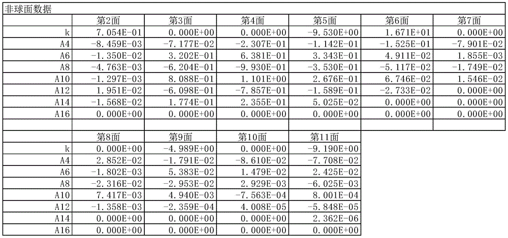
本实施方式中,将光轴方向的轴作为Z,将与光轴正交方向的高度作为H,将圆锥系数作为k,将非球面系数作为A4、A6、A8、A10、A12、A14、A16时,以数式1表示作为透镜面的非球面所采用的非球面形状。In this embodiment, the axis in the optical axis direction is Z, the height in the direction orthogonal to the optical axis is H, the conic coefficient is k, and the aspheric coefficients are A4, A6, A8, A10, A12, A14, A16 , the shape of the aspherical surface adopted as the aspherical surface of the lens surface is represented by
[式1][Formula 1]

接着,示出本实施方式所涉及的摄像镜头的实施例。各实施例中,f表示整个摄像镜头系统的焦距,Fno表示F值,ω表示半视场角,ih表示最大像高。并且,i表示从物体侧开始算起的面号,r表示曲率半径,d表示光轴上的透镜面之间的距离(面间隔),Nd表示d线(基准波长)的折射率,νd表示相对于d线的色散系数。另外,关于非球面,在面号i后面加符号*(星号)表示。Next, an example of the imaging lens according to the present embodiment is shown. In each embodiment, f represents the focal length of the entire camera lens system, Fno represents the F value, ω represents the half angle of view, and ih represents the maximum image height. In addition, i represents the surface number from the object side, r represents the radius of curvature, d represents the distance between the lens surfaces on the optical axis (plane spacing), Nd represents the refractive index of the d line (reference wavelength), and νd represents the Dispersion coefficient relative to the d-line. In addition, regarding the aspherical surface, it is indicated by adding a symbol * (asterisk) after the surface number i.
[实施例1][Example 1]
在以下表1中示出基本的镜头数据。Basic lens data is shown in Table 1 below.
[表1][Table 1]


如表10所示,实施例1的摄像镜头满足条件式(1)至(15)。As shown in Table 10, the imaging lens of Example 1 satisfies Conditional Expressions (1) to (15).
图2为表示实施例1的摄像镜头的球面像差(mm)、像散(mm)、畸变(%)的图。球面像差图中示出F线(486nm)、d线(588nm)、C线(656nm)相对于各波长的像差量。并且,像散图中分别示出弧矢像面S、子午像面T中的d线的像差量(图4、图6、图8、图10、图12、图14、图16及图18中也相同)。如图2所示,可知各像差得到良好的校正。2 is a graph showing spherical aberration (mm), astigmatism (mm), and distortion (%) of the imaging lens of Example 1. FIG. The spherical aberration diagram shows the aberration amounts of the F-line (486 nm), the d-line (588 nm), and the C-line (656 nm) with respect to each wavelength. In addition, the astigmatism diagrams show the aberration amounts of the d-line in the sagittal image plane S and the meridional image plane T, respectively (Fig. 4, Fig. 6, Fig. 8, Fig. 10, Fig. 12, Fig. 14, Fig. 16 and Fig. 18 is also the same). As shown in FIG. 2 , it can be seen that each aberration is satisfactorily corrected.
[实施例2][Example 2]
在以下表2中示出基本的镜头数据。Basic lens data is shown in Table 2 below.
[表2][Table 2]


如表10所示,实施例2的摄像镜头满足条件式(1)至(15)。As shown in Table 10, the imaging lens of Example 2 satisfies Conditional Expressions (1) to (15).
图4为表示实施例2的摄像镜头的球面像差(mm)、像散(mm)、畸变(%)的图。如图4所示,可知各像差得到良好的校正。4 is a graph showing spherical aberration (mm), astigmatism (mm), and distortion (%) of the imaging lens of Example 2. FIG. As shown in FIG. 4 , it can be seen that each aberration is satisfactorily corrected.
[实施例3][Example 3]
在以下表3中示出基本的镜头数据。Basic lens data is shown in Table 3 below.
[表3][table 3]


如表10所示,实施例3的摄像镜头满足条件式(1)至(15)。As shown in Table 10, the imaging lens of Example 3 satisfies Conditional Expressions (1) to (15).
图6为表示实施例3的摄像镜头的球面像差(mm)、像散(mm)、畸变(%)的图。如图6所示,可知各像差得到良好的校正。6 is a graph showing spherical aberration (mm), astigmatism (mm), and distortion (%) of the imaging lens of Example 3. FIG. As shown in FIG. 6 , it can be seen that each aberration is satisfactorily corrected.
[实施例4][Example 4]
在以下表4中示出基本的镜头数据。Basic lens data is shown in Table 4 below.
[表4][Table 4]


如表10所示,实施例4的摄像镜头满足条件式(1)至(15)。As shown in Table 10, the imaging lens of Example 4 satisfies Conditional Expressions (1) to (15).
图8为表示实施例4的摄像镜头的球面像差(mm)、像散(mm)、畸变(%)的图。如图8所示,可知各像差得到良好的校正。8 is a graph showing spherical aberration (mm), astigmatism (mm), and distortion (%) of the imaging lens of Example 4. FIG. As shown in FIG. 8 , it can be seen that each aberration is satisfactorily corrected.
[实施例5][Example 5]
在以下表5中示出基本的镜头数据。Basic lens data is shown in Table 5 below.
[表5][table 5]


如表10所示,实施例5的摄像镜头满足条件式(1)至(15)。As shown in Table 10, the imaging lens of Example 5 satisfies Conditional Expressions (1) to (15).
图10为表示实施例5的摄像镜头的球面像差(mm)、像散(mm)、畸变(%)的图。如图10所示,可知各像差得到良好的校正。10 is a graph showing spherical aberration (mm), astigmatism (mm), and distortion (%) of the imaging lens of Example 5. FIG. As shown in FIG. 10 , it can be seen that each aberration is satisfactorily corrected.
[实施例6][Example 6]
在以下表6中示出基本的镜头数据。Basic lens data is shown in Table 6 below.
[表6][Table 6]


如表10所示,实施例6的摄像镜头满足条件式(1)至(15)。As shown in Table 10, the imaging lens of Example 6 satisfies Conditional Expressions (1) to (15).
图12为表示实施例6的摄像镜头的球面像差(mm)、像散(mm)、畸变(%)的图。如图12所示,可知各像差得到良好的校正。12 is a graph showing spherical aberration (mm), astigmatism (mm), and distortion (%) of the imaging lens of Example 6. FIG. As shown in FIG. 12 , it can be seen that each aberration is satisfactorily corrected.
[实施例7][Example 7]
在以下表7中示出基本的镜头数据。Basic lens data is shown in Table 7 below.
[表7][Table 7]


如表10所示,实施例7的摄像镜头满足条件式(1)至(15)。As shown in Table 10, the imaging lens of Example 7 satisfies Conditional Expressions (1) to (15).
图14为表示实施例7的摄像镜头的球面像差(mm)、像散(mm)、畸变(%)的图。如图14所示,可知各像差得到良好的校正。14 is a graph showing spherical aberration (mm), astigmatism (mm), and distortion (%) of the imaging lens of Example 7. FIG. As shown in FIG. 14 , it can be seen that each aberration is satisfactorily corrected.
[实施例8][Example 8]
在以下表8中示出基本的镜头数据。Basic lens data is shown in Table 8 below.
[表8][Table 8]
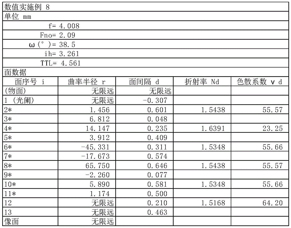


如表10所示,实施例8的摄像镜头满足条件式(1)至(15)。As shown in Table 10, the imaging lens of Example 8 satisfies Conditional Expressions (1) to (15).
图16为表示实施例8的摄像镜头的球面像差(mm)、像散(mm)、畸变(%)的图。如图16所示,可知各像差得到良好的校正。16 is a graph showing spherical aberration (mm), astigmatism (mm), and distortion (%) of the imaging lens of Example 8. FIG. As shown in FIG. 16 , it can be seen that each aberration is satisfactorily corrected.
[实施例9][Example 9]
在以下表9中示出基本的镜头数据。Basic lens data is shown in Table 9 below.
[表9][Table 9]


如表10所示,实施例9的摄像镜头满足条件式(1)至(15)。As shown in Table 10, the imaging lens of Example 9 satisfies Conditional Expressions (1) to (15).
图18为表示实施例9的摄像镜头的球面像差(mm)、像散(mm)、畸变(%)的图。如图18所示,可知各像差得到良好的校正。18 is a graph showing spherical aberration (mm), astigmatism (mm), and distortion (%) of the imaging lens of Example 9. FIG. As shown in FIG. 18 , it can be seen that each aberration is satisfactorily corrected.
如以上说明,本发明的实施方式所涉及的摄像镜头能够实现光学全长小于5mm,远摄比(TTL/f)小于1.2,且全长对角比小于0.9的低背化及F2.4以下的明亮度,而且可实现不仅能够进行70°至78°的广范围的拍摄且具备各像差得到良好校正的高分辨率的小型光学系统。As described above, the imaging lens according to the embodiment of the present invention can achieve a low profile with an optical total length of less than 5 mm, a telephoto ratio (TTL/f) of less than 1.2, and a total length to diagonal ratio of less than 0.9 and F2.4 or less. It is possible to realize a compact optical system with high resolution that not only can capture a wide range of 70° to 78°, but also has excellent correction of various aberrations.
表10中示出实施例1至9所涉及的条件式(1)至(15)的值。Table 10 shows the values of conditional expressions (1) to (15) according to Examples 1 to 9.
[表10][Table 10]

根据本发明所涉及的5片式结构的摄像镜头,将其应用到正推进小型化及低背化的智能手机或移动终端设备等、游戏机或PC等信息终端设备等以及搭载于附带相机功能的家电产品等上的摄像装置时,能够实现该相机的低背化、低F值化、广角化及高性能化。According to the imaging lens of the 5-piece structure according to the present invention, it can be applied to smartphones, mobile terminal devices, etc., which are being miniaturized and low-profile, information terminal devices such as game consoles and PCs, etc. When used as an imaging device on home appliances, etc., the camera can achieve low profile, low F value, wide angle, and high performance.
Claims (10)
Applications Claiming Priority (2)
| Application Number | Priority Date | Filing Date | Title |
|---|---|---|---|
| JP2015-082714 | 2015-04-14 | ||
| JP2015082714A JP6529320B2 (en) | 2015-04-14 | 2015-04-14 | Imaging lens |
Publications (2)
| Publication Number | Publication Date |
|---|---|
| CN106054354A CN106054354A (en) | 2016-10-26 |
| CN106054354B true CN106054354B (en) | 2021-02-05 |
Family
ID=57128969
Family Applications (2)
| Application Number | Title | Priority Date | Filing Date |
|---|---|---|---|
| CN201610228874.1A Expired - Fee Related CN106054354B (en) | 2015-04-14 | 2016-04-13 | camera lens |
| CN201620307938.2U Expired - Fee Related CN205720843U (en) | 2015-04-14 | 2016-04-13 | camera lens |
Family Applications After (1)
| Application Number | Title | Priority Date | Filing Date |
|---|---|---|---|
| CN201620307938.2U Expired - Fee Related CN205720843U (en) | 2015-04-14 | 2016-04-13 | camera lens |
Country Status (3)
| Country | Link |
|---|---|
| US (1) | US9823439B2 (en) |
| JP (1) | JP6529320B2 (en) |
| CN (2) | CN106054354B (en) |
Families Citing this family (23)
| Publication number | Priority date | Publication date | Assignee | Title |
|---|---|---|---|---|
| JP6529320B2 (en) * | 2015-04-14 | 2019-06-12 | カンタツ株式会社 | Imaging lens |
| KR101872857B1 (en) * | 2017-03-14 | 2018-06-29 | 주식회사 엔투에이 | Subminiature wide angle image pickup lens system |
| CN107193108B (en) * | 2017-03-24 | 2019-10-15 | 玉晶光电(厦门)有限公司 | Optical imaging lens |
| CN115016106B (en) | 2017-05-03 | 2024-08-13 | 信泰光学(深圳)有限公司 | Imaging lens |
| CN107121761B (en) * | 2017-07-05 | 2022-12-30 | 浙江舜宇光学有限公司 | Optical imaging lens |
| CN107167902B (en) * | 2017-07-25 | 2022-09-16 | 浙江舜宇光学有限公司 | Optical imaging lens |
| US10775593B2 (en) * | 2017-11-17 | 2020-09-15 | Aac Communication Technologies (Changzhou) Co., Ltd. | Camera optical lens |
| JP6362294B1 (en) * | 2018-01-19 | 2018-07-25 | エーエーシーアコースティックテクノロジーズ(シンセン)カンパニーリミテッドAAC Acoustic Technologies(Shenzhen)Co., Ltd | Imaging lens |
| JP6366156B1 (en) * | 2018-02-09 | 2018-08-01 | エーエーシーアコースティックテクノロジーズ(シンセン)カンパニーリミテッドAAC Acoustic Technologies(Shenzhen)Co., Ltd | Imaging lens |
| TWI712815B (en) * | 2018-03-28 | 2020-12-11 | 先進光電科技股份有限公司 | Optical image capturing system |
| JP7112894B2 (en) * | 2018-06-19 | 2022-08-04 | 東京晨美光学電子株式会社 | imaging lens |
| TWI674450B (en) * | 2018-12-28 | 2019-10-11 | 中揚光電股份有限公司 | Optical imaging lens, imaging device, and electronic device |
| CN110161652B (en) * | 2018-12-30 | 2021-07-30 | 瑞声光学解决方案私人有限公司 | Image pickup optical lens |
| CN110515182B (en) * | 2019-08-19 | 2021-01-08 | 诚瑞光学(常州)股份有限公司 | Image pickup optical lens |
| CN110850563B (en) * | 2019-11-22 | 2021-08-20 | 诚瑞光学(常州)股份有限公司 | Camera optics |
| KR20210081892A (en) | 2019-12-24 | 2021-07-02 | 삼성전자주식회사 | Image sensor and method of manufacturing the same |
| JP7396918B2 (en) * | 2020-02-12 | 2023-12-12 | 東京晨美光学電子株式会社 | imaging lens |
| CN111208626B (en) * | 2020-02-24 | 2021-11-02 | 诚瑞光学(常州)股份有限公司 | Camera optics |
| CN111983790B (en) | 2020-09-03 | 2021-06-04 | 诚瑞光学(苏州)有限公司 | Image pickup optical lens |
| CN112363302B (en) * | 2020-11-25 | 2022-05-17 | 江西晶超光学有限公司 | Optical systems, camera modules and electronic equipment |
| JP7254864B2 (en) * | 2021-09-03 | 2023-04-10 | シャープセンシングテクノロジー株式会社 | Optical system and camera module |
| CN116794803B (en) * | 2022-03-21 | 2025-09-26 | 浙江舜宇光学有限公司 | Imaging lens group |
| CN115452330B (en) * | 2022-09-17 | 2025-04-01 | 齐鲁中科光物理与工程技术研究院 | A three-coordinate measurement and parameter fitting method for hyperbolic aspheric surfaces |
Citations (7)
| Publication number | Priority date | Publication date | Assignee | Title |
|---|---|---|---|---|
| CN102472883A (en) * | 2010-04-13 | 2012-05-23 | 柯尼卡美能达精密光学株式会社 | camera lens |
| CN103703402A (en) * | 2011-06-24 | 2014-04-02 | 柯尼卡美能达株式会社 | Image pickup optical system, image pickup device, and digital apparatus |
| CN103869453A (en) * | 2013-03-19 | 2014-06-18 | 瑞声声学科技(深圳)有限公司 | Imaging lens |
| CN103890630A (en) * | 2011-08-29 | 2014-06-25 | 柯尼卡美能达株式会社 | Imaging optical system, imaging device, and digital equipment |
| CN104007537A (en) * | 2014-01-27 | 2014-08-27 | 玉晶光电(厦门)有限公司 | Optical imaging lens and electronic device with optical imaging lens |
| CN104122646A (en) * | 2013-10-09 | 2014-10-29 | 玉晶光电(厦门)有限公司 | Optical imaging lens and electronic device applying same |
| CN205720843U (en) * | 2015-04-14 | 2016-11-23 | 康达智株式会社 | camera lens |
Family Cites Families (10)
| Publication number | Priority date | Publication date | Assignee | Title |
|---|---|---|---|---|
| EP2357505B1 (en) * | 2008-08-25 | 2014-08-13 | Konica Minolta Opto, Inc. | Image pickup lens, image pickup apparatus and mobile terminal |
| JP5607398B2 (en) * | 2009-04-07 | 2014-10-15 | 富士フイルム株式会社 | IMAGING LENS, IMAGING DEVICE, AND PORTABLE TERMINAL DEVICE |
| TWI440924B (en) * | 2011-09-06 | 2014-06-11 | Largan Precision Co Ltd | Image lens system |
| TWI437261B (en) * | 2012-03-30 | 2014-05-11 | 玉晶光電股份有限公司 | Mobile device and optical imaging lens thereof |
| TWI487934B (en) * | 2012-10-12 | 2015-06-11 | 玉晶光電股份有限公司 | Mobile device and optical imaging lens thereof |
| JP2014153575A (en) * | 2013-02-08 | 2014-08-25 | Konica Minolta Inc | Imaging lens, and imaging device and portable terminal |
| JP6308208B2 (en) * | 2013-02-26 | 2018-04-11 | コニカミノルタ株式会社 | Imaging lens and imaging apparatus |
| JP6257081B2 (en) * | 2013-05-31 | 2018-01-10 | カンタツ株式会社 | Imaging lens |
| WO2015041123A1 (en) * | 2013-09-19 | 2015-03-26 | コニカミノルタ株式会社 | Imaging lens, imaging device, and portable terminal |
| JP6274942B2 (en) * | 2014-03-27 | 2018-02-07 | カンタツ株式会社 | Imaging lens with 5 optical elements |
-
2015
- 2015-04-14 JP JP2015082714A patent/JP6529320B2/en not_active Expired - Fee Related
-
2016
- 2016-04-13 CN CN201610228874.1A patent/CN106054354B/en not_active Expired - Fee Related
- 2016-04-13 CN CN201620307938.2U patent/CN205720843U/en not_active Expired - Fee Related
- 2016-04-14 US US15/099,152 patent/US9823439B2/en not_active Expired - Fee Related
Patent Citations (7)
| Publication number | Priority date | Publication date | Assignee | Title |
|---|---|---|---|---|
| CN102472883A (en) * | 2010-04-13 | 2012-05-23 | 柯尼卡美能达精密光学株式会社 | camera lens |
| CN103703402A (en) * | 2011-06-24 | 2014-04-02 | 柯尼卡美能达株式会社 | Image pickup optical system, image pickup device, and digital apparatus |
| CN103890630A (en) * | 2011-08-29 | 2014-06-25 | 柯尼卡美能达株式会社 | Imaging optical system, imaging device, and digital equipment |
| CN103869453A (en) * | 2013-03-19 | 2014-06-18 | 瑞声声学科技(深圳)有限公司 | Imaging lens |
| CN104122646A (en) * | 2013-10-09 | 2014-10-29 | 玉晶光电(厦门)有限公司 | Optical imaging lens and electronic device applying same |
| CN104007537A (en) * | 2014-01-27 | 2014-08-27 | 玉晶光电(厦门)有限公司 | Optical imaging lens and electronic device with optical imaging lens |
| CN205720843U (en) * | 2015-04-14 | 2016-11-23 | 康达智株式会社 | camera lens |
Also Published As
| Publication number | Publication date |
|---|---|
| CN106054354A (en) | 2016-10-26 |
| JP2016200776A (en) | 2016-12-01 |
| US20160306143A1 (en) | 2016-10-20 |
| CN205720843U (en) | 2016-11-23 |
| JP6529320B2 (en) | 2019-06-12 |
| US9823439B2 (en) | 2017-11-21 |
Similar Documents
| Publication | Publication Date | Title |
|---|---|---|
| CN106054354B (en) | camera lens | |
| CN106483637B (en) | Camera lens | |
| CN111090165B (en) | Camera lens | |
| CN108008519B (en) | camera lens | |
| CN109387927B (en) | camera lens | |
| CN211928289U (en) | Camera lens | |
| CN108931844B (en) | camera lens | |
| CN113238352B (en) | camera lens | |
| CN113238363B (en) | Camera lens | |
| CN204188872U (en) | Pick-up lens | |
| CN204331127U (en) | camera lens | |
| CN107272152B (en) | camera lens | |
| CN204178038U (en) | Pick-up lens | |
| JP6332851B2 (en) | Imaging lens | |
| CN108693630B (en) | Camera lens composed of 5 optical elements | |
| CN203606553U (en) | camera lens | |
| CN110850550A (en) | camera lens | |
| CN111061034A (en) | camera lens | |
| CN110727080B (en) | camera lens | |
| CN107966785B (en) | camera lens | |
| CN109387928A (en) | Camera lens | |
| CN109960016A (en) | camera lens | |
| US10809494B2 (en) | Imaging lens | |
| CN111552055B (en) | Camera lens | |
| CN114791660A (en) | camera lens |
Legal Events
| Date | Code | Title | Description |
|---|---|---|---|
| C06 | Publication | ||
| PB01 | Publication | ||
| SE01 | Entry into force of request for substantive examination | ||
| SE01 | Entry into force of request for substantive examination | ||
| GR01 | Patent grant | ||
| GR01 | Patent grant | ||
| TR01 | Transfer of patent right |
Effective date of registration: 20210813 Address after: Tokyo Patentee after: Tokyo chenmei Optical Electronics Co.,Ltd. Address before: Japan Tochigi Patentee before: Kantatsu Co.,Ltd. |
|
| TR01 | Transfer of patent right | ||
| CF01 | Termination of patent right due to non-payment of annual fee |
Granted publication date: 20210205 |
|
| CF01 | Termination of patent right due to non-payment of annual fee |