CN110827239A - A method for measuring the lateral movement of train wheels - Google Patents
A method for measuring the lateral movement of train wheels Download PDFInfo
- Publication number
- CN110827239A CN110827239A CN201910949515.9A CN201910949515A CN110827239A CN 110827239 A CN110827239 A CN 110827239A CN 201910949515 A CN201910949515 A CN 201910949515A CN 110827239 A CN110827239 A CN 110827239A
- Authority
- CN
- China
- Prior art keywords
- track
- wheel
- camera
- structured light
- plane
- Prior art date
- Legal status (The legal status is an assumption and is not a legal conclusion. Google has not performed a legal analysis and makes no representation as to the accuracy of the status listed.)
- Pending
Links
Images

Classifications
-
- G—PHYSICS
- G06—COMPUTING OR CALCULATING; COUNTING
- G06T—IMAGE DATA PROCESSING OR GENERATION, IN GENERAL
- G06T7/00—Image analysis
- G06T7/0002—Inspection of images, e.g. flaw detection
- G06T7/0004—Industrial image inspection
-
- G—PHYSICS
- G01—MEASURING; TESTING
- G01B—MEASURING LENGTH, THICKNESS OR SIMILAR LINEAR DIMENSIONS; MEASURING ANGLES; MEASURING AREAS; MEASURING IRREGULARITIES OF SURFACES OR CONTOURS
- G01B11/00—Measuring arrangements characterised by the use of optical techniques
- G01B11/002—Measuring arrangements characterised by the use of optical techniques for measuring two or more coordinates
-
- G—PHYSICS
- G01—MEASURING; TESTING
- G01B—MEASURING LENGTH, THICKNESS OR SIMILAR LINEAR DIMENSIONS; MEASURING ANGLES; MEASURING AREAS; MEASURING IRREGULARITIES OF SURFACES OR CONTOURS
- G01B11/00—Measuring arrangements characterised by the use of optical techniques
- G01B11/24—Measuring arrangements characterised by the use of optical techniques for measuring contours or curvatures
-
- G—PHYSICS
- G01—MEASURING; TESTING
- G01B—MEASURING LENGTH, THICKNESS OR SIMILAR LINEAR DIMENSIONS; MEASURING ANGLES; MEASURING AREAS; MEASURING IRREGULARITIES OF SURFACES OR CONTOURS
- G01B21/00—Measuring arrangements or details thereof, where the measuring technique is not covered by the other groups of this subclass, unspecified or not relevant
- G01B21/02—Measuring arrangements or details thereof, where the measuring technique is not covered by the other groups of this subclass, unspecified or not relevant for measuring length, width, or thickness
- G01B21/04—Measuring arrangements or details thereof, where the measuring technique is not covered by the other groups of this subclass, unspecified or not relevant for measuring length, width, or thickness by measuring coordinates of points
- G01B21/042—Calibration or calibration artifacts
-
- G—PHYSICS
- G06—COMPUTING OR CALCULATING; COUNTING
- G06T—IMAGE DATA PROCESSING OR GENERATION, IN GENERAL
- G06T7/00—Image analysis
- G06T7/60—Analysis of geometric attributes
- G06T7/62—Analysis of geometric attributes of area, perimeter, diameter or volume
-
- G—PHYSICS
- G06—COMPUTING OR CALCULATING; COUNTING
- G06T—IMAGE DATA PROCESSING OR GENERATION, IN GENERAL
- G06T7/00—Image analysis
- G06T7/80—Analysis of captured images to determine intrinsic or extrinsic camera parameters, i.e. camera calibration
-
- G—PHYSICS
- G06—COMPUTING OR CALCULATING; COUNTING
- G06T—IMAGE DATA PROCESSING OR GENERATION, IN GENERAL
- G06T2207/00—Indexing scheme for image analysis or image enhancement
- G06T2207/10—Image acquisition modality
- G06T2207/10004—Still image; Photographic image
-
- G—PHYSICS
- G06—COMPUTING OR CALCULATING; COUNTING
- G06T—IMAGE DATA PROCESSING OR GENERATION, IN GENERAL
- G06T2207/00—Indexing scheme for image analysis or image enhancement
- G06T2207/30—Subject of image; Context of image processing
- G06T2207/30108—Industrial image inspection
- G06T2207/30164—Workpiece; Machine component
Landscapes
- Physics & Mathematics (AREA)
- Engineering & Computer Science (AREA)
- General Physics & Mathematics (AREA)
- Computer Vision & Pattern Recognition (AREA)
- Theoretical Computer Science (AREA)
- Quality & Reliability (AREA)
- Geometry (AREA)
- Length Measuring Devices By Optical Means (AREA)
Abstract
Description
技术领域technical field
本发明涉及铁路机车的蛇形运动测量、分析的技术领域,尤其是指一种列车车轮横移的测量方法。The invention relates to the technical field of measurement and analysis of the serpentine motion of a railway locomotive, in particular to a method for measuring the lateral movement of a train wheel.
背景技术Background technique
随着经济社会的发展,交通运输需求猛增,铁路机车作为公认的运力最大的交通工具,其市场需求更加紧张。由于列车是通过轮对踏面、转向架等特殊结构来转弯的,那么在列车直线运行过程中一边向前运动,一边横向摆动的蛇形运动也就不可避免。过于剧烈的蛇形运动不仅会破坏车辆运行的平稳性,还会损坏车轮和钢轨,甚至还可能引发出轨造成重大事故。因此监控列车蛇形运动保障行车安全对于人民人身安全、财产安全至关重要。With the development of economy and society, the demand for transportation has soared. As the recognized means of transportation with the largest capacity, the market demand of railway locomotives is even tighter. Since the train turns through special structures such as wheel set treads and bogies, the serpentine motion of the train moving forward and swinging laterally during the straight running process is inevitable. Excessive serpentine motion will not only disrupt the smooth running of the vehicle, but also damage the wheels and rails, and may even lead to derailment and cause major accidents. Therefore, monitoring the serpentine movement of trains to ensure the safety of driving is very important for people's personal safety and property safety.
因此,本发明希望能够通过设计一种列车车轮横移的测量方法,实时测量列车车轮的横移,当横移超过一定范围时,能够及时发现并通知异常情况。Therefore, the present invention hopes to measure the lateral movement of the train wheel in real time by designing a method for measuring the lateral movement of the train wheel, and when the lateral movement exceeds a certain range, the abnormal situation can be detected and notified in time.
发明内容SUMMARY OF THE INVENTION
本发明的目的在于克服现有技术的缺点与不足,提出了一种基于结构光的列车车轮横移的测量方法,通过三维重建列车车轮和轨道平面以判断蛇形运动的剧烈程度,从而实现对列车行车安全的监控,以便提高铁路运输的安全性。The purpose of the present invention is to overcome the shortcomings and deficiencies of the prior art, and proposes a method for measuring the lateral movement of train wheels based on structured light. Monitoring of train running safety in order to improve the safety of railway transportation.
为实现上述目的,本发明所提供的技术方案为:一种列车车轮横移的测量方法,包括以下步骤:In order to achieve the above purpose, the technical solution provided by the present invention is: a method for measuring the lateral movement of a train wheel, comprising the following steps:
1)列车转向架上布置双目摄像头及结构光光源,拍摄范围包括待测车轮和轨道,调整结构光光源并将线结构光投影在待测车轮和轨道上;其中,需对双目摄像头进行系统标定,获得双目摄像头的内参以及进行立体标定获得双目摄像头之间的相对位置关系矩阵,利用内外参数对左右图像进行立体校正预处理;1) A binocular camera and a structured light source are arranged on the train bogie. The shooting range includes the wheel and track to be tested. Adjust the structured light source and project the linear structured light on the wheel and track to be tested; System calibration, obtain the internal parameters of the binocular camera and perform stereo calibration to obtain the relative position relationship matrix between the binocular cameras, and use the internal and external parameters to perform stereo correction preprocessing on the left and right images;
2)对图像进行概率Hough直线检测,提取出左视图和右视图中的结构光直线;以直线角度作为匹配特征,将左、右图像中的结构光线段进行一一匹配,再把同一直线段的两个端点进行匹配;采用双目立体视觉算法,通过标定得到的双目内参以及外参计算出特征点的三维空间坐标;2) Perform probabilistic Hough line detection on the image to extract the structured light lines in the left and right views; take the straight line angle as the matching feature, match the structured light segments in the left and right images one by one, and then match the same straight line segment The two end points of the two end points are matched; the binocular stereo vision algorithm is used to calculate the three-dimensional space coordinates of the feature points through the binocular internal parameters and external parameters obtained by calibration;
3)根据对应特征点的空间坐标,对车轮、轨道进行三维重建,建立车轮与轨道的三维空间方程;3) According to the spatial coordinates of the corresponding feature points, three-dimensional reconstruction of the wheel and the track is carried out, and the three-dimensional space equation of the wheel and the track is established;
4)通过计算车轮圆心在轨道平面的投影点与轨道边缘的距离,以此作为列车车轮的横移,同时设定正常横移范围,若存在车轮圆心在轨道平面的投影点与轨道边缘的距离在正常横移范围内,则判定列车行驶正常,若存在车轮圆心在轨道平面的投影点与轨道边缘的距离超出正常横移范围,则判定列车行驶异常。4) Calculate the distance between the projection point of the wheel center on the track plane and the edge of the track as the lateral movement of the train wheel, and set the normal lateral movement range. If there is a distance between the projection point of the wheel center on the track plane and the edge of the track If the distance between the projection point of the wheel center on the track plane and the edge of the track exceeds the normal traverse range, it is determined that the train is running abnormally.
在步骤1)中,采用平行放置的双目摄像头和多个结构光光源,放置在列车转向架上,调整摄像头与结构光光源角度,使双目摄像头能够拍摄到结构光分别以不同角度照射在车轮和轨道上的图像。In step 1), a binocular camera and a plurality of structured light sources placed in parallel are used, placed on the train bogie, and the angle between the camera and the structured light source is adjusted, so that the binocular camera can capture the structured light irradiated at different angles. Images on wheels and tracks.
在步骤1)中,采用张正友标定法对双目摄像头进行标定,获得包括SX、SY、u0、v0、f的内参数,其中SX、SY是摄像头芯片单个像素的物理尺寸,u0、v0为光轴光心的像素坐标,f为相机的焦距;对双目摄像头相对位置关系进行立体标定,得到外参数R、T,其中旋转因子



平移因子中的tx、ty、tz为右摄像头原点相对左摄像头的平移距离,设左摄像头坐标系为XL,右摄像头坐标系为XR,能够得到两摄像头的相对公式为XR=RXL+T。t x , ty , and t z in the translation factor are the translation distances of the origin of the right camera relative to the left camera. Let the coordinate system of the left camera be X L and the coordinate system of the right camera be X R , and the relative formula of the two cameras can be obtained as X R = RXL+T.
在步骤2)中,对图像进行概率Hough直线检测,检测出结构光映射在图像上的直线,选取结构光在物体边缘的端点作为特征点并进行匹配,计算后选取车轮上3个不共线的特征点P1(x1,y1,z1)、P2(x2,y2,z2)、P3(x2,y2,z2)和轨道一侧的2个特征点Q1、Q2及另一侧的1个特征点Q3;In step 2), the probability Hough line detection is performed on the image, the straight line mapped by the structured light on the image is detected, the endpoint of the structured light on the edge of the object is selected as the feature point and matched, and after calculation, three non-collinear lines on the wheel are selected The feature points P 1 (x 1 , y 1 , z 1 ), P 2 (x 2 , y 2 , z 2 ), P 3 (x 2 , y 2 , z 2 ) and 2 feature points on the track side Q 1 , Q 2 and a feature point Q 3 on the other side;
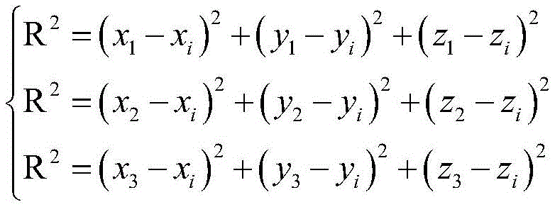
在步骤3)中,利用3个不共线点确定一个平面、车轮边缘点P1、P2、P3到圆心距离相等且均为R的原则,设定常数Ai、Bi、Ci、Di,其中(Ai,Bi,Ci)为车轮平面的法向量,解圆心O(xi,yi,zi)空间坐标:In step 3), the three non-collinear points are used to determine a plane, the wheel edge points P 1 , P 2 , P 3 have equal distances from the center of the circle and are all R, and set the constants A i , B i , C i , D i , where (A i ,B i ,C i ) is the normal vector of the wheel plane, and the solution center O(x i ,y i ,z i ) space coordinates:
Aix+Biy+Ciz+Di=0A i x+B i y+C i z+D i =0

设定常数m、n、p,利用轨道同一侧的2个特征点Q1、Q2计算出轨道所在的空间直线l的方程:
在步骤4)中,依次计算圆心在轨道平面的投影V(x,y,z)和V与轨道边缘的距离d;过圆心O(xi,yi,zi)作轨道平面的垂线交于投影点V(x,y,z),得到垂线的参数方程:In step 4), calculate the projection V (x,y, z ) of the center of the circle on the orbital plane and the distance d between V and the edge of the orbital; Intersecting at the projection point V(x, y, z), the parametric equation of the vertical line is obtained:

将垂线的参数方程带入轨道平面方程α,求出投影点V(x,y,z)在参数方程中对应的参数t:The parametric equation of the vertical line is brought into the orbit plane equation α, and the parameter t corresponding to the projection point V(x, y, z) in the parametric equation is obtained:

再把参数t带入直线的参数方程就求出投影点具体的空间坐标V(x,y,z);利用轨道边缘同侧的两个点Q1、Q2,求投影点V到轨道边缘的距离:Then bring the parameter t into the parametric equation of the straight line to obtain the specific spatial coordinates V(x, y, z) of the projection point; use the two points Q 1 and Q 2 on the same side of the track edge to find the projection point V to the track edge the distance:

设定正常横移范围[dmin,dmax],若圆心在轨道平面的投影点与轨道边缘的距离dmin<d<dmax,则此时列车运行正常;若圆心在轨道平面的投影点与轨道边缘的距离超出正常横移范围,则此时列车运行异常。Set the normal traverse range [d min , d max ]. If the distance between the projection point of the circle center on the track plane and the track edge is d min <d < d max , the train runs normally; if the circle center is at the projection point of the track plane If the distance from the edge of the track exceeds the normal traverse range, the train runs abnormally at this time.
本发明与现有技术相比,具有如下优点与有益效果:Compared with the prior art, the present invention has the following advantages and beneficial effects:
1、对行车过程中车轮与轨道之间形成的横移进行实时监控,行车安全得到了保障。1. Real-time monitoring of the lateral movement formed between the wheel and the track during the driving process ensures the driving safety.
2、通过对车轮和轨道边缘点进行三维重建,以非接触的方法获取横移信息,保障安全的同时提高了测量精度。2. Through the three-dimensional reconstruction of the edge points of the wheel and the track, the traverse information is obtained in a non-contact method, which ensures the safety and improves the measurement accuracy.
3、结构光的辅助极大地提高了特征点匹配的效率,降低了算法的时间复杂度。3. The assistance of structured light greatly improves the efficiency of feature point matching and reduces the time complexity of the algorithm.
附图说明Description of drawings
图1为本发明逻辑流程示意图。FIG. 1 is a schematic diagram of the logic flow of the present invention.
具体实施方式Detailed ways
下面结合具体实施例对本发明作进一步说明。The present invention will be further described below in conjunction with specific embodiments.
如图1所示,本实施例所提供的列车车轮横移的测量方法,包括以下步骤:As shown in Figure 1, the method for measuring the lateral movement of a train wheel provided by this embodiment includes the following steps:
步骤1:在室内用张正友标定法对双目摄像头进行标定,获得双目摄像头的内参以及两台摄像头之间的相对位置关系矩阵。打印尺寸已知的棋盘格标定板,拍摄不同位置、不同角度、不同姿态的标定板图像10~20张,对每一张标定图像提取亚像素角点坐标进行摄像头标定。获得摄像头内参数:SX、Sy、u0、v0、f,其中SX、Sy是相机芯片单个像素的物理尺寸,u0、v0为光轴光心的像素坐标,f为相机的焦距;对双目摄像头相对位置关系进行立体标定,得到外参数R、T,其中旋转因子

平移因子中的tx、ty、tz为右摄像头原点相对左摄像头的平移距离。设左摄像头坐标系为XL,右摄像头坐标系为XR,可得到两摄像头的相对公式为XR=RXL+T。并对左右图像进行立体校正预处理。The t x , ty , and t z in the translation factor are the translation distances of the origin of the right camera relative to the left camera. Assuming that the coordinate system of the left camera is XL and the coordinate system of the right camera is X R , the relative formula of the two cameras can be obtained as X R =RX L +T. The stereo correction preprocessing is performed on the left and right images.
步骤2:在列车转向架上布置双目摄像头及结构光光源,拍摄范围包括待测车轮和轨道,调整结构光光源并将线结构光投影在待测车轮和轨道上。Step 2: Arrange a binocular camera and a structured light source on the train bogie, the shooting range includes the wheel and track to be tested, adjust the structured light source and project the linear structured light on the wheel and track to be tested.
步骤3:对图像进行概率Hough直线检测,提取出左视图和右视图中的结构光直线,根据直线角度将左右图像中的结构光线段进行一一匹配。Step 3: Perform probabilistic Hough line detection on the image, extract the structured light lines in the left view and the right view, and match the structured light segments in the left and right images one by one according to the angle of the line.
步骤4:提取同一直线同一端点在左右摄像机的图像坐标(Xl,Yl)、(Xr,Yr),采用双目立体视觉算法,通过标定得到的左右摄像机内参以及外参R、T计算出特征点的三维空间坐标P(xC,yC,zC)。Step 4: Extract the image coordinates (X l , Y l ) and (X r , Y r ) of the same end point of the same line on the left and right cameras, and use the binocular stereo vision algorithm to calibrate the left and right camera internal parameters and external parameters R, T Calculate the three-dimensional space coordinates P(x C , y C , z C ) of the feature points.

步骤5:利用3个不共线点确定一个平面、车轮边缘点P1、P2、P3到圆心距离相等且均为R的原则,设一般常数Ai、Bi、Ci、Di,其中(Ai,Bi,Ci)为车轮平面的法向量,解圆心O(xi,yi,zi)空间坐标:Step 5: Use 3 non-collinear points to determine a plane, the wheel edge points P 1 , P 2 , P 3 have equal distances from the center of the circle and are all R, set the general constants A i , B i , C i , D i , where (A i ,B i ,C i ) is the normal vector of the wheel plane, and the solution center O(x i ,y i ,z i ) space coordinates:
Aix+Biy+Ciz+Di=0A i x+B i y+C i z+D i =0

设一般常数m、n、p,利用轨道同一侧的2个特征点Q1、Q2计算出轨道所在的空间直线l的方程:其中(x0,y0,z0)为直线l上的某点,(m,n,p)为直线l的方向向量。设一般常数A、B、C、D,利用轨道同一侧的2个特征点Q1、Q2及另一侧的1个特征点Q3,计算出车轮所在平面α的一般方程:Ax+By+Cz+D=0,其中(A,B,C)为平面α的法向量;Assuming general constants m, n, and p, the equation of the space straight line l where the orbit is located is calculated by using the two characteristic points Q 1 and Q 2 on the same side of the orbit: Where (x 0 , y 0 , z 0 ) is a point on the straight line l, and (m, n, p) is the direction vector of the straight line l. Assuming general constants A, B, C, D, using two feature points Q 1 , Q 2 on the same side of the track and one feature point Q 3 on the other side, calculate the general equation of the plane α where the wheel is located: Ax+By +Cz+D=0, where (A, B, C) is the normal vector of plane α;
步骤6:依次计算圆心O(xi,yi,zi)在轨道平面α的投影V(x,y,z)和投影点V与轨道边缘的距离d。过圆心O(xi,yi,zi)作轨道平面的垂线交于投影点V(x,y,z),得到垂线的参数方程:Step 6: Calculate the projection V(x, y, z) of the center O(x i , y i , zi ) on the orbital plane α and the distance d between the projection point V and the orbital edge in turn. The vertical line of the orbital plane through the center O(x i , y i , z i ) intersects the projection point V(x, y, z), and the parametric equation of the vertical line is obtained:
将垂线的参数方程带入轨道平面方程α,求出投影点V(x,y,z)在参数方程中对应的参数t:The parametric equation of the vertical line is brought into the orbit plane equation α, and the parameter t corresponding to the projection point V(x, y, z) in the parametric equation is obtained:

再把参数t带入直线的参数方程就求出投影点具体的空间坐标V(x,y,z)。利用轨道边缘内侧的两个点Q1、Q2,求投影点V到轨道边缘的距离:Then the parameter t is brought into the parametric equation of the straight line to obtain the specific spatial coordinates V(x, y, z) of the projection point. Using the two points Q 1 and Q 2 inside the track edge, find the distance from the projected point V to the track edge:

步骤7:设定正常横移范围[dmin,dmax],若圆心在轨道平面的投影点与轨道内边缘的距离dmin<d<dmax,则此时列车运行正常;若圆心在轨道平面的投影点与轨道边缘的距离超出正常横移范围,则此时列车运行异常。Step 7: Set the normal traverse range [d min , d max ], if the distance between the projection point of the circle center on the track plane and the inner edge of the track d min <d < d max , the train runs normally at this time; if the circle center is on the track If the distance between the projected point of the plane and the edge of the track exceeds the normal traverse range, the train runs abnormally at this time.
以上所述实施例只为本发明之较佳实施例,并非以此限制本发明的实施范围,故凡依本发明之形状、原理所作的变化,均应涵盖在本发明的保护范围内。The above-mentioned embodiments are only preferred embodiments of the present invention, and are not intended to limit the scope of implementation of the present invention. Therefore, any changes made according to the shape and principle of the present invention should be included within the protection scope of the present invention.
Claims (4)




Priority Applications (1)
| Application Number | Priority Date | Filing Date | Title |
|---|---|---|---|
| CN201910949515.9A CN110827239A (en) | 2019-10-08 | 2019-10-08 | A method for measuring the lateral movement of train wheels |
Applications Claiming Priority (1)
| Application Number | Priority Date | Filing Date | Title |
|---|---|---|---|
| CN201910949515.9A CN110827239A (en) | 2019-10-08 | 2019-10-08 | A method for measuring the lateral movement of train wheels |
Publications (1)
| Publication Number | Publication Date |
|---|---|
| CN110827239A true CN110827239A (en) | 2020-02-21 |
Family
ID=69548710
Family Applications (1)
| Application Number | Title | Priority Date | Filing Date |
|---|---|---|---|
| CN201910949515.9A Pending CN110827239A (en) | 2019-10-08 | 2019-10-08 | A method for measuring the lateral movement of train wheels |
Country Status (1)
| Country | Link |
|---|---|
| CN (1) | CN110827239A (en) |
Citations (5)
| Publication number | Priority date | Publication date | Assignee | Title |
|---|---|---|---|---|
| CN105374038A (en) * | 2015-11-11 | 2016-03-02 | 石家庄铁道大学 | Car-mounted double camera locomotive wheel track displacement image detection system and detection method |
| CN108001481A (en) * | 2017-12-07 | 2018-05-08 | 石家庄铁道大学 | Vehicular wheel track displacement image detecting method and detection device based on bidifly light source |
| CN109029228A (en) * | 2018-05-30 | 2018-12-18 | 中南大学 | It is a kind of for measuring the system and method for rail vehicle offset opposite with rail |
| CN109801302A (en) * | 2018-12-14 | 2019-05-24 | 华南理工大学 | A kind of ultra-high-tension power transmission line foreign matter detecting method based on binocular vision |
| CN110203210A (en) * | 2019-06-19 | 2019-09-06 | 厦门金龙联合汽车工业有限公司 | A kind of lane departure warning method, terminal device and storage medium |
-
2019
- 2019-10-08 CN CN201910949515.9A patent/CN110827239A/en active Pending
Patent Citations (5)
| Publication number | Priority date | Publication date | Assignee | Title |
|---|---|---|---|---|
| CN105374038A (en) * | 2015-11-11 | 2016-03-02 | 石家庄铁道大学 | Car-mounted double camera locomotive wheel track displacement image detection system and detection method |
| CN108001481A (en) * | 2017-12-07 | 2018-05-08 | 石家庄铁道大学 | Vehicular wheel track displacement image detecting method and detection device based on bidifly light source |
| CN109029228A (en) * | 2018-05-30 | 2018-12-18 | 中南大学 | It is a kind of for measuring the system and method for rail vehicle offset opposite with rail |
| CN109801302A (en) * | 2018-12-14 | 2019-05-24 | 华南理工大学 | A kind of ultra-high-tension power transmission line foreign matter detecting method based on binocular vision |
| CN110203210A (en) * | 2019-06-19 | 2019-09-06 | 厦门金龙联合汽车工业有限公司 | A kind of lane departure warning method, terminal device and storage medium |
Non-Patent Citations (3)
| Title |
|---|
| PING WANG ET AL.: ""Development and Application of Wheel-set Lateral Displacement Test System in High Speed Railway Turnout Zone"", 《SOUTHWEST JIAOTONG UNICERSITY》 * |
| 宋子彬 等: ""双目视觉车轮姿态提取的位移检测方法"", 《科学技术与工程》 * |
| 郑小波: ""基于机器视觉的机车车辆动态偏移量检测研究及实现"", 《中国优秀博硕士学位论文全文数据库(硕士) 信息科技辑》 * |
Similar Documents
| Publication | Publication Date | Title |
|---|---|---|
| CN102749061B (en) | Steel rail abrasion measuring method based on dynamic template | |
| RU2743020C2 (en) | System and method for monitoring railway wheels | |
| CN107677212B (en) | Wheel multi-parameter online measuring system based on structured light and measuring method thereof | |
| CN102012217B (en) | Binocular vision-based three-dimensional geometric shape measurement method for large-shape object | |
| CN114368411B (en) | A monitoring and early warning method for train derailment safety | |
| CN101532827B (en) | A deviation correction method for laser vision rail wear measurement | |
| CN102901457B (en) | Dynamic measurement method and system for train wheel diameter | |
| CN100447527C (en) | Anti-flash positioning system | |
| CN104655043B (en) | One kind is based on contour registration method in the measurement of machine vision train guide rail profile | |
| CN105783779B (en) | The real-time form identification of rail profile and distortion calibration method based on three layers of matching | |
| CN108955576A (en) | Multi-line structured light self-calibrating method and system in profile of steel rail dynamic detection | |
| CN103499302A (en) | Camshaft diameter online measuring method based on structured light visual imaging system | |
| CN109443245A (en) | A kind of multi-line structured light vision measuring method based on homography matrix | |
| CN105292180A (en) | Non-contact wheel set dimension online detection method and device based on various sensors | |
| CN107421502B (en) | A method for automatic measurement of the limit of railway freight cars | |
| CN104648440B (en) | A kind of rail wheels geometric parameters on-line measurement system and its method | |
| CN115112044A (en) | A wheelset size measurement method based on multi-line structured light point cloud data | |
| CN107764201B (en) | Minimum area profile matching method for railway abrasion measurement based on line structured light | |
| CN110686622A (en) | Method for measuring train wheel attack angle | |
| CN105241384A (en) | Computer vision-based steel rail weld offset measurement method | |
| CN107101594A (en) | A kind of method for extracting wheel track wheel space wheel rim minimum point | |
| CN104236866A (en) | Automobile headlamp test data error correction method based on driving direction | |
| CN107150701B (en) | Train wheel geometric dimension measurement method and its detection device | |
| CN205373648U (en) | Contact net geometric parameters dynamic verification device based on triangulation | |
| CN110827239A (en) | A method for measuring the lateral movement of train wheels |
Legal Events
| Date | Code | Title | Description |
|---|---|---|---|
| PB01 | Publication | ||
| PB01 | Publication | ||
| SE01 | Entry into force of request for substantive examination | ||
| SE01 | Entry into force of request for substantive examination | ||
| WD01 | Invention patent application deemed withdrawn after publication | ||
| WD01 | Invention patent application deemed withdrawn after publication |
Application publication date: 20200221 |