Background
Such a contact element comprises a contact body extending in a plane along an extension plane and at least one contact leg extending from the contact body along the extension plane.
The support rail can be used, for example, for supporting various electrical devices that perform control functions and/or evaluation functions, such as electronic devices, or electrical connection devices, such as terminals, or the like. On the support rail, electrical devices can be combined with one another in a modular manner, for example in the field of industrial devices, in order to provide electrical functions.
In such a support rail, a support rail bus system can be provided which establishes an electrical connection of the electrical devices mounted on the support rail to one another, so that signals, for example control signals, can be exchanged between the electrical devices and, for example, also a current supply for the electrical devices can be provided. Such a support rail bus system is formed, for example, by bus elements which are mounted in the support rail and each have a plurality of contact elements, by means of which electrical contact can be made with the electrical device mounted on the support rail.
The electronic device may, for example, have a circuit board on which electrical and electronic components for providing electrical and electronic functions, such as control functions and automation functions, are placed. If such an electronic device is mounted on a carrier rail, the circuit board is brought into electrical contact with the contact elements of the bus bar element by means of contact springs arranged on the circuit board, so that the electronic device is electrically connected to the carrier rail bus system in this way. This should be done automatically as much as possible when mounting the electronic equipment to the support rail.
In order to mount the electronic device on the support rail, the electronic device is placed on the support rail, for example, by means of a pivot edge of the fastening device, and is pivoted toward the support rail, so that the electronic device is locked with the support rail by means of the fastening device, and furthermore, the circuit board present in the electronic device is in electrical contact with the bus elements of the support rail bus system. When the electronic device is pivoted relative to the supporting rail, the circuit board is brought into electrical contact with the contact elements of the bus bar element, so that the contact springs of the circuit board are in electrical contact with the contact elements of the bus bar element.
However, electronic devices are also known which are inserted on a support rail and which are able to come into contact with the bus system when inserted.
There is thus a need to increase the number of contact elements per bus element, which requires a reduction in the structure of the contact elements. It is therefore particularly desirable to use contact elements which extend planarly along the extension plane and which therefore have a small space requirement in the direction along the normal perpendicular to the extension plane.
In this case, however, it must be ensured that the contact legs arranged on the contact bodies of the contact elements have sufficient elasticity so that they can be deflected in a suitable manner when the circuit board is mounted on the contact elements and, after the circuit board has been mounted, provide sufficient pressure for electrical contacting. It is necessary here to provide the contact legs with sufficient elasticity on the one hand, but also sufficiently stable on the other hand, so that (plastic) bending or breaking of the contact legs does not occur during the mounting of the circuit board.
The contact element known from EP 1575136B 1 extends in a plane along an extension plane and has contact legs arranged on a contact body, which contact legs form contact prongs for electrical contact with a corresponding counter-contact element.
The contact element in the form of a blade-receiving contact known from DE 102008062578B 3 is an integral part of a stamped grid and has contact legs which together form a contact fork for mounting an opposing contact element.
Disclosure of Invention
The object of the present invention is to provide an electrical contact element for supporting a bus element of a rail bus system, which has a small space requirement in the normal direction perpendicular to its plane of extension and which achieves a reliable contact with a corresponding counter-contact element.
This object is achieved by a body having the features of claim 1.
Accordingly, the contact body has a first thickness, measured perpendicular to the plane of extension, and the at least one contact leg has a second thickness, smaller than the first thickness.
The contact element extends in a plane along the extension plane and can be designed, for example, in one piece, so that one or more contact legs are connected in one piece to the contact body and project from the contact body. By means of the contact legs, an electrical contact with a corresponding counter-contact element, for example one or more contact springs of a circuit board, is established. In order to adjust the elasticity of the contact leg, which extends along the extension plane in the same plane as the contact body, the thickness of the contact leg is adjusted relative to the contact body, so that the desired elasticity of the contact leg is achieved.
By reducing the thickness, the elasticity of the at least one contact leg is increased.
In the contact element according to the invention, the elasticity of the contact legs is increased by reducing the thickness of the contact legs relative to the contact body. In this way, the counter-contact element can be inserted reliably, for example, into a contact fork formed by two contact legs, for example, under elastic deformation of the contact legs, wherein the elasticity of the contact legs enables the contact legs to be deflected in a sufficient manner when the counter-contact element is inserted, without (plastic) bending or breaking on the contact legs occurring, and furthermore, in the inserted state of the counter-contact element, the contact legs bear against the counter-contact element with sufficient pressure, so that reliable electrical contact with the counter-contact element is achieved.
Different designs of the contact elements can be considered.
In a first variant, the contact element can be designed as a sheet metal blank made of metal and extending in a plane along the plane of extension. The contact element is therefore produced in one piece as a stamped part and extends in a plane along the extension plane without bending the segments and thus protruding from the extension plane. The thickness of the at least one contact leg can in this case be adjusted, for example, by a punching process in which the at least one contact leg is punched to a specific thickness which is reduced relative to the contact body.
For example, the thickness of the contact body may be in the range 0.5mm to 1mm, for example 0.6 mm. The thickness of the at least one contact leg may then be, for example, in the range of 0.2mm to 0.8mm, for example 0.4 mm.
In a second variant, the contact element is designed as a folded sheet metal blank made of metal. The contact element still extends in a plane along the plane of extension, but here it is formed by two folding halves which are folded onto one another about a folding line, so that the folding faces lie against one another at least in sections in a planar manner and together form the contact body. In this way, the material thickness can be doubled in particular in the region of the contact bodies by the folding surfaces being folded over one another in the region of the contact bodies. At least one contact leg is formed by only one fold plane, so that only a single material thickness is present in the region of the contact leg.
For the production, the contact element according to the second variant can first be produced as a stamped part with fold faces which are connected to one another and extend in a planar manner along an extension plane. After blanking, the folding surfaces are folded over each other about the folding lines, thereby producing the contact element.
The contact element has, for example, one or more contact legs which can be elastically deformed relative to the contact body, so that a reliable mounting of the one or more counter-contact elements is achieved. In this case, the two contact legs can together form a contact fork, into which a corresponding counter-contact element, for example a circuit board, on which a contact spring is arranged, can be inserted in order to form an electrical contact. During insertion, the contact leg is elastically deformed in the extension plane and, after insertion of the counter-contact element, rests against the counter-contact element under an elastic pretension (with the direction of the force extending along the extension plane).
It is conceivable and possible here for one or both contact legs of the contact fork to have a (second) thickness which is smaller than the (first) thickness of the contact body. It may be sufficient that only one of the contact legs has a reduced thickness, so that a higher elasticity is provided on this contact leg. It is likewise conceivable and possible and advantageous for both contact legs of the contact fork to have a reduced thickness relative to the contact body.
In a specific embodiment, the contact element can also have a plurality of contact prongs, for example two contact prongs, each of which has a pair of contact legs. In this way, the plurality of opposing contact elements can be brought into electrical contact with the contact element. In this case, the contact prongs can project in the same direction from the contact body. However, it is also conceivable and possible for the contact prongs to project from the contact body in different directions, so that different counter-contact elements can be attached to different contact prongs in different directions.
For example, the first contact fork makes electrical contact with the circuit board and for this purpose projects in the vertical direction from the contact body. In contrast, the second contact fork makes electrical contact with the contact element of the other bus element, for example, and for this purpose projects from the contact body in a horizontal direction transverse to the vertical direction.
The contact elements may be an integral part of the bus elements of the support rail bus system. To construct the support rail bus system, a plurality of bus elements may be arranged in a row with one another in the horizontal direction. For this purpose, the contact elements of each bus element can have a contact prong on the one hand and a contact pin extending in the horizontal direction from the contact body to the other side, so that the contact elements of a first bus element can be inserted into the contact prongs of the contact elements of an adjacent, second bus element, for example by means of the contact pins, in order to make electrical contact.
Contact elements of the type described here can be used advantageously in bus elements of a support rail bus system. However, this should not be construed restrictively. In principle, contact elements of the type described here can also be modified to completely different types of elements, for example elements for connecting electrically conductive lines to one another in plug connectors or the like.
Detailed Description
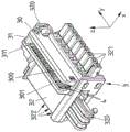
Fig. 1 shows a schematic representation of an electronic device 1, which has a housing 10 and a circuit board 11 (see fig. 2A and 2B) disposed therein and can be designed, for example, for carrying control functions and/or automation functions in the field of industrial devices.
The electronic device 1 can be mounted on the support rail 2 in the form of a hat rail by means of the fastening means 100 on the underside of the housing 10 and can be combined with other electrical or electronic devices, for example in order to provide an electrical device in the interior of a switchgear cabinet, which is formed by modular components.
For mounting on the support rail 2, the housing 10 of the electronic device 1 can be mounted by means of the pivot edge 101 of the fastening device 100 on the lateral flange 23 of the arm 21 of the support rail 2 and can pivot about this pivot edge 101 in the pivoting direction S toward the support rail 2 until the locking edge 102 opposite the pivot edge 101 locks with the flange 24 of the support rail 2 on the arm 22 opposite the arm 21 and thus holds the electronic device 1 on the support rail 2 in a form-fitting manner.
In this connection, it should be noted in principle that the electronic device 1 can also be plugged onto the carrier rail 2, i.e. mounted on the carrier rail 2 in a straight plugging direction.
The support rail 2 has a U-shaped configuration in cross section with a base 20 and opposite arms 21,22 to which a flange 23,24 is respectively connected. By engaging with the lateral flanges 23,24, the housing 10 of the electronic device 1 is connected to the support rail 2 in a form-fitting manner and is thus fixed to the support rail 2.
In the space of the support rail 2 formed between the arms 21,22, bus elements 3, 3' of the support rail bus system are placed, which bus elements realize the electrical connection between the different electrical and electronic devices mounted on the support rail 2. For this purpose, the bus element 3 has an upwardly projecting contact section 30, into which contact section 30 the circuit board 11 of the electronic device 1 arranged in the housing 10 can be inserted, so that an electrical contact with the carrier rail bus system is established. The bus elements 3 are connected to each other, for example by intermediate elements 3', and can be combined with each other modularly, so that a modular support rail bus system is provided.
Fig. 2A, 2B and 3A, 3B show a specific embodiment of a bus element 3 on which an electronic device 1 with a circuit board 11 can be mounted in electrical contact. Fig. 2A and 2B show the electronic device 1 here mounted on the bus element 3, while fig. 3A, 3B show individual perspective views of the bus element 3.
The bus element 3 has a plurality of contact elements 4 spaced apart from one another in the transverse direction Y, each extending in the plane of the extension plane E, for contacting the contact springs 110 of the circuit board 11. An extension plane E extends through the horizontal direction X and the vertical direction Z, wherein the planar contact elements 4 extend in a plurality of parallel planes with respect to one another.
Fig. 4A to 4C and fig. 5 show an embodiment of the contact element 4. Each contact element 4 has a contact body 40 and a contact leg 42,410,430 extending therefrom for electrical contact with other contact elements (contact pin 42 and contact fork 41 formed by contact leg 410) or with a corresponding contact spring 110 of the circuit board 11 (contact fork 43 formed by contact leg 430).
In the exemplary embodiment according to fig. 4A to 4C and in the exemplary embodiment according to fig. 5, the contact element 4 is designed as a one-piece sheet metal part. The contact legs 410 of the contact tines 41 and the contact pins 42 extend in the horizontal direction X from the contact body 40 to different sides, so that electrical contact is established with the other contact elements 4 of the other bus elements 3, 3'. The contact pins 42 are inserted into corresponding contact pins 321 on the main body 32 of the bus element 3, while the contact tines 41 are accessible through contact openings 322 on the rear face of the main body 32 opposite the contact pins 321.
In contrast, the contact fork 43 formed by the contact leg 430 projects in the vertical direction Z from the contact body 40 and into the contact section 30 formed by the two arms 300, 301. Between the contact legs 430 of the contact fork 43, the contact springs 110 arranged on the circuit board 11 can be inserted into the circuit board 11 of the electronic device 1, so that the contact elements 4 can be brought into electrical contact with the corresponding contact springs 110 of the circuit board 11 by means of the contact legs 430.
The arms 300,301 are spaced apart from each other along the horizontal direction X and constitute an intermediate space into which the circuit board 11 can be inserted.
Each contact leg 430 of the contact fork 43 is received on an arm 300,301 so that the circuit board 11 is pushed between the contact legs 430 of the contact forks 43 of the different contact elements 4 arranged on the bus member 3 by inserting the circuit board 11 between the arms 300, 301.
The printed circuit board 11 has a plurality of contact springs 110, wherein the same contact springs 110 are arranged on both sides of the printed circuit board 11, so that pairs of contact springs 110 are formed, each corresponding to a contact element 4. Thus, double-sided contact with the corresponding pair of contact springs 110 is achieved by the contact legs 430 of the contact tines 43.
A reliable contact with the corresponding contact spring 110 of the circuit board 11 is to be achieved by the contact leg 430 of the contact fork 43. For this purpose, the contact legs 430 can be elastically deformed along the plane of extension E of the contact element 4, so that, when the circuit board 11 is inserted between the contact legs 430 of the contact tines 43, the contact legs 430 can be elastically deflected in the plane of extension E and, after insertion of the circuit board 11, bear with sufficient pressure against the corresponding contact springs 110 of the circuit board 11, so that a reliable electrical contact is established in this way.
In order to adjust the elasticity of contact leg 430, thickness D2 of contact leg 430 is reduced relative to thickness D1 of contact body 40, so that the elasticity of contact leg 430 is increased compared to contact body 40 (the elasticity of contact leg 430 in extension plane E is determined on the one hand by the planar extension of contact leg 430 in this extension plane E, on the other hand by the material thickness, on the third hand by the material properties; the elasticity increases with decreasing material thickness in the case of the same planar shape).
Reducing the thickness D2 of the contact leg 430 relative to the thickness D1 of the contact body 40 achieves increased resiliency, particularly without changing the planar shape of the contact leg 430. (it is also possible, for example, to alternatively consider adjusting the elasticity of the contact legs 430, for example by lengthening the contact legs 430, but this would lead to an increase in the installation space requirement.)
The reduction of the material thickness of the contact legs 430 can be achieved in different ways.
In this way, in the exemplary embodiment according to fig. 4A to 4C, the material thickness of contact leg 430 is reduced relative to contact body 40, i.e., contact leg 430 is subjected to an additional punching process, in which the material thickness of contact leg 430 is reduced by punching. In the exemplary embodiment according to fig. 4A to 4C, the contact element 4 is designed as a sheet metal blank. After the production of the contact element 4 by blanking, the contact leg 430 is subjected to an additional blanking process and the thickness D2 of the contact leg 430 is adjusted in a desired manner in this way.
In the exemplary embodiment according to fig. 5, the contact element 4 is embodied as a folded sheet metal blank, in contrast to this. In fig. 5, the contact element 4 is shown after blanking but before folding, with fold halves 4A, 4B, which are folded over each other along a fold line L. The material thickness of the contact element 4 is thereby doubled in the region of the contact body 40, in the region of the contact pin 42 and in the region of the contact leg 410, so that after folding, the contact leg 430 of the contact fork 43 has, in particular, a reduced material thickness relative to the contact body 40.
In the exemplary embodiment according to fig. 4A to 4C, the contact leg 410 of the contact tine 41 has a reduced thickness D2, as does the contact leg 430 of the contact tine 43. For this purpose, the contact leg 410 is advantageously also subjected to an additional punching process together with the contact leg 430, so that the thickness D2 is reduced.
In the exemplary embodiment according to fig. 5, in contrast to this, the material thickness of the contact leg 410 of the contact tine 41 is doubled by the two folded halves 4A, 4B.
The contact element 4 is a component of the bus element 3 and is used for electrical contact with the other bus elements 3, 3' and, in addition, for electrical contact with a circuit board 11 of the electronic device 1. In this case, the bus bar element 3 is fixed to the support rail 2 by the fixing element 320 in the form of a latching element projecting laterally from the body 32, by inserting the body 32 into the space of the support rail 2 formed between the arms 21,22 and by fixing the fixing element 320 around the lateral flanges 23,24 on the arms 21,22 and thus fixing the bus bar element 3 to the support rail 2 in a form-fitting manner.
In order to mount the electronic device 1 on the support rail 2, the housing 10 of the electronic device 1 is mounted by means of the pivot edge 101 of the fastening device 100 on the lateral flange 23 of the support rail 2 as shown in fig. 2A and is pivoted in the pivoting direction S toward the support rail 2 until the opposite latching edge 102 comes into engagement with the flange 24 and the electronic device 1 is thus positively fastened on the support rail 2 as shown in fig. 2B.
When the electronic device 1 is pivoted in the pivoting direction S towards the support rail 2, the printed circuit board 11 is guided between the arms 300,301 of the contact section 30 of the bus element 3. The printed circuit board 11 is positively fixed by the fixing points 111 inside the housing 10 of the electronic device 1 and thus pivots together with the housing 10 when the housing 10 pivots.
When the circuit board 11 is inserted into the contact section 30, the contact legs 430 of the contact prongs 43 of the respective contact 4 are slid onto the respective contact spring 110 on the circuit board 11 by pivoting the housing 10. This is achieved in particular in the case of (weak) elastic deformation of the contact legs 430 in the plane of extension E, so that, when the circuit board 11 is completely inserted, the contact legs 430 rest against the corresponding contact springs 110 of the circuit board 11 under elastic pretensioning.
Since the contact elements 4 and the contact springs 110 have relatively small dimensions, in particular in the transverse direction Y, guide elements 31,112 are provided on the side of the circuit board 11 and on the side of the bus bar element 3, which guide elements provide a direct guidance of the circuit board 11 on the bus bar element 3 when the circuit board 11 is pivoted in. In this way, it can be ensured that the contact element 4 is brought into precise contact with the contact spring 110 of the circuit board 11 and slides along the contact spring 110.
In this case, in particular, the mounting of the circuit board 11 on the bus bar element 3 is independent of tolerances which may be present in the fastening between the circuit board 11 and the housing 10, since the insertion of the circuit board 11 into the contact section 30 of the bus bar element 3 takes place in a defined, guided manner as a result of the direct guidance of the circuit board 11 on the bus bar element 3.
The guide element 31 on the side of the bus bar element 3 is arranged between the arms 300,301 of the contact section 30 and has on the outside a partially rounded guide surface 310 extending obliquely to the vertical direction Z and an inwardly directed abutment surface 311 opposite the guide surface 310.
In contrast, the guide elements of the printed circuit board 11 are formed by recesses 112 in the printed circuit board 11, which form a guide edge 113 and an opposite abutment edge 114. The recess 112 can be shaped, for example by grinding, in the region of the bottom edge 115 of the circuit board 11 and introduced therein during the production of the circuit board 11.
When the electronic device 1 is mounted on the support rail 2 by swinging the housing 10 around the swinging edge 101, the guide elements 31 of the bus members 3 come into sliding contact with their guide surfaces 310 with the guide edges 113 on the recesses 112 of the circuit board 11. When the housing 10 is pivoted in the pivoting direction S, the guide element 31 of the bus bar element 3 slides with the aid of the guide surface 310 on the guide edge 113, wherein the contact between the guide element 31 and the circuit board 11 is formed in particular in the region of the lower corner of the guide edge 113. During pivoting, the printed circuit board 11 is thus guided on the guide element 31 and has a defined position relative to the bus bar element 3, in particular in the transverse direction Y, so that the contact element 4 is ensured to strike the contact spring 110 of the printed circuit board 11 in a defined manner with the contact leg 430 of the contact fork 43.
In the mounted state, as shown in fig. 2B, the contact surface 311 of the guide element 31 of the bus element 3 contacts the contact edge 114 inside the recess 112 of the circuit board 11, so that the position of the circuit board 11 relative to the bus element 3 is also determined when the electronic device 1 is already mounted.
Since the pivoting movement of the circuit board 11 to the contact sections 30 of the bus bar elements 3 takes place in a guided manner, it is possible in particular to prevent the contact legs 430 of the contact elements 4 from eventually coming into contact with the circuit board 11 next to the corresponding contact springs 110, which could lead to the contact legs 430 becoming embedded in the circuit board material. Furthermore, it is reliably avoided that the contact leg 430 of the contact tine 43 of the contact element 4 makes electrical contact with the contact spring 110 adjacent to the respective contact spring 110.
The concept on the basis of the invention is not limited to the embodiments described above, but can in principle also be implemented in an entirely different type of manner.
Thus, the bus elements may have other configurations, such as other numbers of contacts.
Furthermore, the contact elements may also have a different form than described herein. The number of contact pins and/or contact prongs provided on the contact element can also vary.
The mounting of the electronic device on the supporting rail can advantageously be carried out by swinging. However, this is not limited thereto. In principle, it is also conceivable and possible to mount the electronic device on the support rail, for example, in a linear mounting direction.
Description of the reference numerals
1 electronic device
10 casing
100 fixing device
101 swing edge
102 locking edge
11 circuit board
110 contact spring
111 fixed position
112 groove
113 leading edge
114 abutting edge
115 bottom edge
2 supporting guide rail
20 base
21,22 arms
23,24 Flange
3, 3' bus element
30 contact section
300,301 arm
31 guide element
310 guide surface
311 contact surface
32 main body
320 fixing element
321 contact pin
322 contact opening
4 contact element
4A, 4B folded halves
40 contact body
41 contact fork
410 contact leg (fork shaped component)
42 contact pin
43 contact fork
430 contact leg (fork shaped component)
D1, D2 thickness
L fold line
S direction of oscillation