CN115053411A - System comprising a plug contact carrier and at least one plug contact element, plug contact carrier, plug contact element and plug connector - Google Patents
System comprising a plug contact carrier and at least one plug contact element, plug contact carrier, plug contact element and plug connector Download PDFInfo
- Publication number
- CN115053411A CN115053411A CN202180014260.2A CN202180014260A CN115053411A CN 115053411 A CN115053411 A CN 115053411A CN 202180014260 A CN202180014260 A CN 202180014260A CN 115053411 A CN115053411 A CN 115053411A
- Authority
- CN
- China
- Prior art keywords
- plug contact
- plug
- latching
- contact element
- contact carrier
- Prior art date
- Legal status (The legal status is an assumption and is not a legal conclusion. Google has not performed a legal analysis and makes no representation as to the accuracy of the status listed.)
- Pending
Links
Images


Classifications
-
- H—ELECTRICITY
- H01—ELECTRIC ELEMENTS
- H01R—ELECTRICALLY-CONDUCTIVE CONNECTIONS; STRUCTURAL ASSOCIATIONS OF A PLURALITY OF MUTUALLY-INSULATED ELECTRICAL CONNECTING ELEMENTS; COUPLING DEVICES; CURRENT COLLECTORS
- H01R13/00—Details of coupling devices of the kinds covered by groups H01R12/70 or H01R24/00 - H01R33/00
- H01R13/40—Securing contact members in or to a base or case; Insulating of contact members
- H01R13/42—Securing in a demountable manner
- H01R13/428—Securing in a demountable manner by resilient locking means on the contact members; by locking means on resilient contact members
- H01R13/432—Securing in a demountable manner by resilient locking means on the contact members; by locking means on resilient contact members by stamped-out resilient tongue snapping behind shoulder in base or case
-
- H—ELECTRICITY
- H01—ELECTRIC ELEMENTS
- H01R—ELECTRICALLY-CONDUCTIVE CONNECTIONS; STRUCTURAL ASSOCIATIONS OF A PLURALITY OF MUTUALLY-INSULATED ELECTRICAL CONNECTING ELEMENTS; COUPLING DEVICES; CURRENT COLLECTORS
- H01R11/00—Individual connecting elements providing two or more spaced connecting locations for conductive members which are, or may be, thereby interconnected, e.g. end pieces for wires or cables supported by the wire or cable and having means for facilitating electrical connection to some other wire, terminal, or conductive member, blocks of binding posts
- H01R11/03—Individual connecting elements providing two or more spaced connecting locations for conductive members which are, or may be, thereby interconnected, e.g. end pieces for wires or cables supported by the wire or cable and having means for facilitating electrical connection to some other wire, terminal, or conductive member, blocks of binding posts characterised by the relationship between the connecting locations
- H01R11/05—Individual connecting elements providing two or more spaced connecting locations for conductive members which are, or may be, thereby interconnected, e.g. end pieces for wires or cables supported by the wire or cable and having means for facilitating electrical connection to some other wire, terminal, or conductive member, blocks of binding posts characterised by the relationship between the connecting locations the connecting locations having different types of direct connections
-
- H—ELECTRICITY
- H01—ELECTRIC ELEMENTS
- H01R—ELECTRICALLY-CONDUCTIVE CONNECTIONS; STRUCTURAL ASSOCIATIONS OF A PLURALITY OF MUTUALLY-INSULATED ELECTRICAL CONNECTING ELEMENTS; COUPLING DEVICES; CURRENT COLLECTORS
- H01R12/00—Structural associations of a plurality of mutually-insulated electrical connecting elements, specially adapted for printed circuits, e.g. printed circuit boards [PCB], flat or ribbon cables, or like generally planar structures, e.g. terminal strips, terminal blocks; Coupling devices specially adapted for printed circuits, flat or ribbon cables, or like generally planar structures; Terminals specially adapted for contact with, or insertion into, printed circuits, flat or ribbon cables, or like generally planar structures
- H01R12/70—Coupling devices
- H01R12/71—Coupling devices for rigid printing circuits or like structures
- H01R12/712—Coupling devices for rigid printing circuits or like structures co-operating with the surface of the printed circuit or with a coupling device exclusively provided on the surface of the printed circuit
- H01R12/716—Coupling device provided on the PCB
-
- H—ELECTRICITY
- H01—ELECTRIC ELEMENTS
- H01R—ELECTRICALLY-CONDUCTIVE CONNECTIONS; STRUCTURAL ASSOCIATIONS OF A PLURALITY OF MUTUALLY-INSULATED ELECTRICAL CONNECTING ELEMENTS; COUPLING DEVICES; CURRENT COLLECTORS
- H01R12/00—Structural associations of a plurality of mutually-insulated electrical connecting elements, specially adapted for printed circuits, e.g. printed circuit boards [PCB], flat or ribbon cables, or like generally planar structures, e.g. terminal strips, terminal blocks; Coupling devices specially adapted for printed circuits, flat or ribbon cables, or like generally planar structures; Terminals specially adapted for contact with, or insertion into, printed circuits, flat or ribbon cables, or like generally planar structures
- H01R12/50—Fixed connections
- H01R12/51—Fixed connections for rigid printed circuits or like structures
- H01R12/55—Fixed connections for rigid printed circuits or like structures characterised by the terminals
- H01R12/58—Fixed connections for rigid printed circuits or like structures characterised by the terminals terminals for insertion into holes
- H01R12/585—Terminals having a press fit or a compliant portion and a shank passing through a hole in the printed circuit board
Landscapes
- Coupling Device And Connection With Printed Circuit (AREA)
- Connector Housings Or Holding Contact Members (AREA)
Abstract
描述和呈现了一种由插接接触载体(2)和至少一个插接接触元件(3)构成的系统(1),其中,至少一个插接接触元件(3)具有至少一个插口元件(4)和/或至少一个销钉元件(5)和/或用于直接接触电路板的至少一个插头元件(6),并且其中,至少一个插接接触元件(3)具有连接区域(14),该连接区域将接触区域(4,5,6)相互连接,其中,在连接状态下,至少一个插接接触元件(3)定位和固定在插接接触载体(2)中。说明一种由插接接触载体和至少一个插接接触元件构成的系统的目的,其中,可以以特别简单的方式将插接接触元件与插接接触载体连接并定位和固定在插接接触载体中,由此来实现,即至少一个插接接触元件(3)通过卡锁连接固定在插接接触载体(2)中,其中,卡锁连接布置在插接接触元件(3)的连接区域中。

A system (1) consisting of a plug contact carrier (2) and at least one plug contact element (3) is described and presented, wherein the at least one plug contact element (3) has at least one socket element (4) and/or at least one pin element ( 5 ) and/or at least one plug element ( 6 ) for direct contact with the circuit board, and wherein the at least one plug contact element ( 3 ) has a connection area ( 14 ) which The contact areas ( 4 , 5 , 6 ) are connected to one another, wherein in the connected state at least one plug contact element ( 3 ) is positioned and fixed in the plug contact carrier ( 2 ). The object of specifying a system consisting of a plug-in contact carrier and at least one plug-in contact element, wherein the plug-in contact element can be connected to the plug-in contact carrier in a particularly simple manner and positioned and fixed in the plug-in contact carrier. , it is achieved that at least one plug contact element ( 3 ) is fixed in the plug contact carrier ( 2 ) by means of a latching connection, wherein the latch connection is arranged in the connection region of the plug contact element ( 3 ).
Description
技术领域technical field
本发明从一种由插接接触载体和至少一个插接接触元件构成的系统出发,其中,至少一个插接接触元件具有至少一个插口元件和/或至少一个销钉元件和/或用于直接接触电路板的至少一个插头元件,并且其中,至少一个插接接触元件具有连接区域,该连接区域将接触区域相互连接,其中,至少一个插接接触元件在连接状态下定位和固定在插接接触载体中。The invention proceeds from a system comprising a plug contact carrier and at least one plug contact element, wherein the at least one plug contact element has at least one socket element and/or at least one pin element and/or is used for direct contacting of the circuit At least one plug element of the board, and wherein the at least one plug contact element has a connection area which connects the contact areas to one another, wherein the at least one plug contact element is positioned and fixed in the plug contact carrier in the connected state .
背景技术Background technique
根据一个设计方案,用于进行直接接触的插头元件具有两个接触支脚,所述接触支脚可以插入电路板的相应的接触孔中,从而可以仅仅通过插入插头元件来接触电路板。According to one configuration, the plug element for direct contact has two contact legs which can be inserted into corresponding contact holes in the circuit board, so that the circuit board can be contacted only by inserting the plug element.
根据另一个设计方案,用于直接接触电路板的插头元件关于插口元件和/或销钉元件基本上垂直地取向。因此,存在有足够的空间供连结和布置待连接的部件使用。According to a further refinement, the plug elements for direct contact with the circuit board are oriented substantially perpendicularly with respect to the socket elements and/or the pin elements. Thus, there is sufficient space for joining and arranging the components to be joined.
至少一个插接接触元件和插接接触载体在本发明的范围中如此设计,使得插接接触元件可以被插入到插接接触载体中以与插接接触载体连接。Within the scope of the invention, the at least one plug contact element and the plug contact carrier are designed such that the plug contact element can be inserted into the plug contact carrier for connection to the plug contact carrier.
此外,本发明涉及一种用于容纳在插接接触载体中的插接接触元件,其中,插接接触元件构造用于形成上述系统;一种用于容纳至少一个插接接触元件的插接接触载体,其中,插接接触载体构造用于形成上述系统;和一种插接连接器、优选地用于优选地经由插接连接接触电路板的直接插接连接器,其包括由插接接触载体和至少一个插接接触元件构成的系统且此外包括壳体。Furthermore, the invention relates to a plug contact element for accommodating in a plug contact carrier, wherein the plug contact element is designed to form the system described above; a plug contact for accommodating at least one plug contact element a carrier, wherein a plug contact carrier is configured for forming the system described above; and a plug connector, preferably a direct plug connector for contacting a circuit board, preferably via a plug connection, comprising a plug contact carrier The system is formed with at least one plug contact element and also includes a housing.
用于将至少两个电子部件电接触的插接连接器在现有技术中是已知的。尤其地,电路板的接触对插接连接器的引导电流的接触元件的定位以及固定提出了较高的要求。Plug connectors for electrically contacting at least two electronic components are known from the prior art. In particular, the contacting of the circuit board places high demands on the positioning and fixing of the current-carrying contact elements of the plug-in connector.
从现有技术DE 20 2016 105 358 U1中已知一种用于将电构件与电路板连结的插接接触元件,其中,插接接触元件可插入到插接接触载体中,并且其中,插接接触元件经由装配框架以及经由卡锁连接定位在接触载体中。From the prior art DE 20 2016 105 358 U1 a plug contact element for connecting electrical components to a circuit board is known, wherein the plug contact element can be inserted into a plug contact carrier, and wherein the plug contact The contact elements are positioned in the contact carrier via the mounting frame and via the latching connection.
此外,从出版文件DE 10 2013 111 571 B4中已知一种插接连接器,其中,布置在插接接触载体中的插接接触元件具有用于与电路板连结的焊接销钉,并且其中,插接接触元件在接触插口的区域中具有固定开口,所述固定开口在与插接接触载体的相应突起相互作用中在安装状态下固定插接接触元件。然而,这样的设计方案具有如下缺点,即固定开口的不完全卡入影响接触插口的接触开口尺寸以及就此而言影响接触质量。Furthermore, a plug connector is known from
此外,从现有技术中已知,借助于热填缝将以插接接触元件的形式的接触金属与壳体连接以确保限定的定位。为此,必须首先预定位插接接触元件,以便在正确的位置中对插接接触元件进行热填缝。该方法具有如下缺点,即需要附加的耗费的过程步骤来制造上述系统。此外,该方法以各个构件之间的相对较大的间隙为条件。Furthermore, it is known from the prior art to connect the contact metal in the form of a plug-in contact element to the housing by means of thermal caulking to ensure a defined positioning. For this purpose, the plug contact elements must first be pre-positioned in order to thermally caulk the plug contact elements in the correct position. This method has the disadvantage that additional complex process steps are required to manufacture the system described above. Furthermore, the method is conditional on relatively large gaps between the individual components.
发明内容SUMMARY OF THE INVENTION
从所阐述的现有技术出发,本发明的目的是说明一种由插接接触载体和至少一个插接接触元件构成的系统,其中,可以以特别简单的方式将插接接触元件与插接接触载体连接并定位和固定在插接接触载体中。此外,本发明的目的是说明一种相应的插接接触载体、一种相应的插接接触元件和一种相应的插接连接器。Starting from the stated prior art, the object of the present invention is to specify a system consisting of a plug-in contact carrier and at least one plug-in contact element, in which the plug-in contact element can be connected to the plug-in contact in a particularly simple manner The carrier is connected and positioned and fixed in the plug contact carrier. Furthermore, the object of the present invention is to specify a corresponding plug contact carrier, a corresponding plug contact element and a corresponding plug connector.
根据第一教导,上述目的通过具有专利权利要求1的特征的上面描述的由插接接触载体和至少一个插接接触元件构成的系统由此来实现,即至少一个插接接触元件通过卡锁连接固定在插接接触载体中,其中,卡锁连接布置在插接接触元件的连接区域中。According to a first teaching, the above-mentioned object is achieved by the above-described system of a plug-in contact carrier and at least one plug-in contact element having the features of
根据本发明,至少一个插接接触元件可以被放入、详细地插入到插接接触载体中,其中,插接接触载体和至少一个插接接触元件如此设计,使得至少一个插接接触元件在插入之后直接通过卡锁连接固定。由于卡锁连接布置在插接接触元件的连接区域中且因此不布置在插接接触元件的接触区域中,因此卡锁连接对接触区域没有影响且尤其对接触的质量没有影响。即使不完全的卡锁也不一定导致更差的接触质量。According to the invention, the at least one plug contact element can be inserted into the plug contact carrier in detail, wherein the plug contact carrier and the at least one plug contact element are designed in such a way that the at least one plug contact element is inserted into the plug contact carrier. After that, it is directly fixed by the card lock connection. Since the snap connection is arranged in the connection region of the plug contact element and therefore not in the contact region of the plug contact element, the snap connection has no influence on the contact region and in particular on the quality of the contact. Even incomplete latching does not necessarily lead to worse contact quality.
结果,根据本发明的系统因此一方面确保了至少一个插接接触元件与插接接触载体的特别简单的连接,并且另一方面确保了与另外的结构元件的改善的接触。As a result, the system according to the invention thus ensures, on the one hand, a particularly simple connection of the at least one plug contact element to the plug contact carrier and, on the other hand, an improved contact with further structural elements.
例如,根据本发明的卡锁连接构造为后卡锁。在此,后卡锁是指卡锁在插入方向上在布置在插接接触载体处的卡锁元件或卡锁配对元件后面进行。For example, the latching connection according to the invention is configured as a rear latch. In this context, rear locking means that the locking takes place in the insertion direction behind a locking element or a locking counterpart element which is arranged on the plug-in contact carrier.
根据一个优选的设计方案,至少一个插接接触元件具有卡锁元件、尤其以卡锁鼻或卡锁钩的形式的卡锁元件,并且插接接触载体具有卡锁配对元件、尤其以凹口的形式的卡锁配对元件,其中,卡锁元件在插接接触元件的插入状态下与卡锁配对元件形成卡锁连接,并且其中,卡锁元件布置在至少一个插接接触元件的连接区域中。According to a preferred refinement, at least one of the plug contact elements has a latching element, in particular in the form of a latching nose or a latching hook, and the plug contact carrier has a latching counterpart element, in particular in the form of a recess. A latching counterpart element in the form of the latching element forming a latching connection with the latching counterpart element in the inserted state of the plug contact element, and wherein the latching element is arranged in the connection region of the at least one plug contact element.
同样可以考虑的是,插接接触载体具有卡锁元件、尤其以卡锁鼻或卡锁钩的形式的卡锁元件,该卡锁元件在插入状态下卡入到布置在至少一个插接接触元件处的卡锁配对元件、尤其以凹口的形式的卡锁配对元件中。It is also conceivable for the plug contact carrier to have latching elements, in particular in the form of latching lugs or latching hooks, which, in the inserted state, snap into place at least one of the plug contact elements. in the latching counterpart element at the location, in particular in the form of a recess.
特别优选地,卡锁元件和卡锁配对元件如此构造,使得卡锁元件在插入期间优选地通过卡锁配对元件复位弹性地变形和/或偏转。在插入状态下,卡锁元件具有原始形状或位置,由此实现卡锁连接。Particularly preferably, the latching element and the latching counterpart element are designed in such a way that the latching element is elastically deformed and/or deflected during insertion, preferably by means of the latching counterpart element reset. In the inserted state, the latching element has the original shape or position, whereby the latching connection is achieved.
根据另一个优选的设计方案,至少一个插接接触元件通过刚好一个卡锁连接固定在插接接触载体中。根据该设计方案,除了卡锁连接之外,在至少一个插接接触元件和插接接触载体之间可选地存在另外的限定的接触区域、尤其以止挡部和/或支承面和/或引导面的形式的接触区域,其中,限定的接触区域使插接接触元件在插接接触载体中的位置稳定。According to another preferred configuration, the at least one plug contact element is fixed in the plug contact carrier by exactly one latching connection. According to this configuration, in addition to the latching connection, there may optionally be further defined contact areas between the at least one plug contact element and the plug contact carrier, in particular with stops and/or bearing surfaces and/or A contact area in the form of a guide surface, wherein the defined contact area stabilizes the position of the plug contact element in the plug contact carrier.
另一个有利的设计方案特征在于,至少一个插接接触元件如此设计,使得在插入状态下不仅存在与插接接触载体的限定的接触区域、尤其以止挡部和/或支承面和/或引导面的形式的接触区域,而且存在如下区域,在其中在部件之间存在中间空间。这样的中间空间例如可以通过至少局部地使插接接触元件变薄实现。在重要区域中,例如在插口元件和/或销钉元件的区域中,因此至少一个插接接触元件不安放在插接接触载体上。特别优选地,与插接接触载体的限定的接触区域布置在插接接触元件的连接区域中。Another advantageous configuration is characterized in that the at least one plug contact element is designed in such a way that in the inserted state not only a defined contact area with the plug contact carrier, in particular with stops and/or bearing surfaces and/or guides, is present A contact area in the form of a face, but also an area in which there is an intermediate space between the components. Such an intermediate space can be achieved, for example, by thinning the plug contact elements at least in regions. In important regions, for example in the region of socket elements and/or pin elements, the at least one plug contact element is therefore not placed on the plug contact carrier. Particularly preferably, a defined contact area with the plug contact carrier is arranged in the connection area of the plug contact element.
这样的设计方案具有如下优点,即在插接接触元件和/或插接接触载体的平面度方面的由制造引起的公差对插接接触元件在插接接触载体中的位置基本上没有影响。Such a configuration has the advantage that manufacturing-induced tolerances in the flatness of the plug contact element and/or the plug contact carrier have substantially no influence on the position of the plug contact element in the plug contact carrier.
根据下一个设计方案,插接接触元件优选地在连接区域中具有至少两个支承面,插接接触元件利用所述支承面安放在插接接触载体上。优选地,支承面的总和总体上小于可能的支承面的50%或小于其40%或小于其30%。According to a further refinement, the plug contact element preferably has at least two bearing surfaces in the connecting region, with which the plug contact element rests on the plug contact carrier. Preferably, the sum of the bearing surfaces is generally less than 50% or less than 40% or less than 30% of the possible bearing surfaces.
特别优选地,插接接触元件具有刚好两个支承面,插接接触元件利用所述支承面安放在插接接触载体上。该设计方案是一方面确保插接接触元件在插接接触载体中的稳定位置与另一方面确保部件之间的足够自由空间之间的最佳折衷,以便使由制造引起的公差的影响最小化。Particularly preferably, the plug contact element has exactly two bearing surfaces with which the plug contact element rests on the plug contact carrier. This design is an optimal compromise between ensuring a stable position of the plug contact element in the plug contact carrier on the one hand and ensuring sufficient free space between the components on the other hand in order to minimize the influence of manufacturing-induced tolerances .
特别优选地,插接接触载体具有用于在插入方向上定位至少一个插接接触元件的至少一个止挡面,其中,插接接触元件具有至少一个配对止挡面,并且其中,每个配对止挡面在插入状态下贴靠在插接接触载体的止挡面处。通过限定数量的止挡面可以确保插接接触元件在插入状态下限定地定位,其中,止挡面尤其限制插接接触元件在插入方向上的运动。根据一个特别优选的设计方案,插接接触载体具有至少两个止挡面,其中,插接接触元件在插入状态下利用两个配对止挡面贴靠在两个止挡面处。以这种方式,可以保证插接接触元件在插接接触载体中的特别精确的定位。Particularly preferably, the plug contact carrier has at least one stop surface for positioning at least one plug contact element in the insertion direction, wherein the plug contact element has at least one mating stop surface, and wherein each mating stop In the inserted state, the stop surface abuts against the stop surface of the plug-in contact carrier. A defined positioning of the plug contact element in the inserted state can be ensured by a defined number of abutment surfaces, wherein the stop surface in particular limits the movement of the plug contact element in the insertion direction. According to a particularly preferred configuration, the plug contact carrier has at least two stop surfaces, wherein the plug contact element in the inserted state abuts against the two stop surfaces with two mating stop surfaces. In this way, a particularly precise positioning of the plug contact element in the plug contact carrier can be ensured.
根据一个特别优选的设计方案,至少一个插接接触元件借助于冲压由金属扁平材料制成。以这种方式制造的插接接触元件有利地与现有技术中已知的冲压-弯曲接触部区别在于特别简单的制造过程。如果在插接接触元件处布置有卡锁元件,则该卡锁元件可以直接在冲压时被成形。According to a particularly preferred configuration, the at least one plug contact element is produced from a flat metal material by means of stamping. The plug contact element produced in this way advantageously differs from the punch-bend contacts known from the prior art by a particularly simple production process. If a detent element is arranged on the plug contact element, the detent element can be formed directly during stamping.
插接接触载体优选地由塑料组成。The plug contact carrier preferably consists of plastic.
此外有利的是,插接接触载体具有至少三个引导元件、尤其以引导面的形式的引导元件,其中,引导元件使至少一个插接接触元件在插入期间和/或在插入状态下在三个空间方向上引导和/或稳定。It is also advantageous if the plug contact carrier has at least three guide elements, in particular guide elements in the form of guide surfaces, wherein the guide elements cause the at least one plug contact element to move between three during insertion and/or in the inserted state. Steering and/or stabilizing in a spatial direction.
根据一个特别优选的设计方案,插接接触载体具有至少一个引导元件、优选地以引导轨道的形式的引导元件,其中,引导元件在插入方向上延伸,并且其中,为了连接部件,插接接触元件沿着引导元件被插入到插接接触载体中。According to a particularly preferred configuration, the plug contact carrier has at least one guide element, preferably in the form of a guide rail, wherein the guide element extends in the insertion direction, and wherein the plug contact element for connecting the components It is inserted into the plug contact carrier along the guide element.
如果插接接触载体具有多个插接接触元件,则在插接接触载体处优选地针对每个插接接触元件布置有引导元件、优选地以引导轨道的形式的引导元件。此外有利的是,引导元件在插接接触元件的两个侧面处在插入方向上延伸,从而可以确保插接接触元件笔直地引入到插接接触载体中。If the plug contact carrier has a plurality of plug contact elements, a guide element, preferably in the form of a guide rail, is preferably arranged on the plug contact carrier for each plug contact element. Furthermore, it is advantageous if the guide element extends on both sides of the plug contact element in the insertion direction, so that a straight introduction of the plug contact element into the plug contact carrier can be ensured.
根据另一个设计方案,引导元件构造为引导壳体,其中,引导壳体在插接接触元件的三个侧面处在插入方向上延伸。该设计方案在插入时已经确保插接接触元件的特别精确的定位。According to another configuration, the guide element is designed as a guide housing, wherein the guide housing extends in the insertion direction on three sides of the plug contact element. This configuration already ensures a particularly precise positioning of the plug contact element during insertion.
根据一个特别优选的设计方案,引导壳体具有凹部,插接接触元件的卡锁元件在插入状态下卡入到该凹部中。在该设计方案中,引导壳体的凹部作为卡锁配对元件起作用。According to a particularly preferred configuration, the guide housing has a recess into which the latching element of the plug-in contact element snaps into place in the inserted state. In this configuration, the recess of the guide housing acts as a latching counterpart element.
根据本发明的第二教导,开头阐述的目的通过开头提及的用于与插接接触载体连接的插接接触元件由此来实现,即插接接触元件构造用于形成根据前述实施方案所述的系统。为此,插接接触元件具有上述设计方案中的至少一个的特征。According to a second teaching of the present invention, the object stated at the outset is achieved by the plug contact element mentioned at the outset for connection to the plug contact carrier, ie the plug contact element is designed to form the above-mentioned embodiment. system. For this purpose, the plug contact element has the features of at least one of the above-mentioned embodiments.
此外,用于与插接接触载体连结的插接接触元件也可以根据接下来的设计方案中的一个构造。Furthermore, the plug contact element for connection to the plug contact carrier can also be configured according to one of the following refinements.
根据另一个有利的设计方案,插接接触元件通过冲压制造并且在冲压之后在至少一个接触区域中通过压印后加工。通过塑性变形实现了表面质量以及通过冲压过程产生的切割棱边的改善。因此,结果可以改善与插接接触元件的电连结。According to a further advantageous configuration, the plug contact element is produced by punching and after punching is processed by embossing in at least one contact region. The surface quality and the cutting edge produced by the stamping process are improved by plastic deformation. Consequently, the electrical connection to the plug-in contact element can be improved as a result.
特别优选地,插接接触元件不仅在插口元件的区域中而且在销钉元件的区域中压印。Particularly preferably, the plug contact element is embossed not only in the region of the socket element but also in the region of the pin element.
此外有利的是,插口元件至少局部地渐缩。这具有如下优点,即在冲压之后在渐缩部的区域中可以简单且精确地校准接触开口尺寸。It is also advantageous if the socket element tapers at least in regions. This has the advantage that the size of the contact opening can be adjusted simply and precisely in the region of the taper after stamping.
插接接触元件的另一个有利的设计方案特征在于,销钉元件如此加宽,使得销钉元件比插接接触元件的其余部分的材料厚度更宽。这具有如下优点,即在销钉元件连结时,接触由于重叠面的扩大而变得更容易。例如,销钉元件可以在冲压之后通过塑性变形加宽。A further advantageous configuration of the plug contact element is characterized in that the pin element is widened in such a way that the material thickness of the pin element is wider than the remainder of the plug contact element. This has the advantage that, when the pin elements are joined, the contact becomes easier due to the enlargement of the overlapping surface. For example, the pin elements can be widened by plastic deformation after stamping.
根据本发明的第三教导,开头阐述的目的通过开头描述的用于容纳至少一个插接接触元件的插接接触载体由此来实现,即插接接触载体构造用于形成根据前述实施方案所述的系统。为此,插接接触元件具有上述设计方案中的至少一个的特征。According to a third teaching of the present invention, the object stated at the outset is achieved by the plug contact carrier described at the outset for accommodating at least one plug contact element, ie the plug contact carrier is designed to form the form according to the preceding embodiments. system. For this purpose, the plug contact element has the features of at least one of the above-mentioned embodiments.
根据第四教导,开头阐述的目的通过一种插接连接器、尤其用于优选地经由插接连接接触电路板的直接插接连接器来实现,其包括根据上述设计方案中的一个所述的由插接接触载体和至少一个插接接触元件构成的系统且此外包括壳体。According to a fourth teaching, the object stated at the outset is achieved by a plug connector, in particular a direct plug connector for contacting circuit boards, preferably via a plug connection, which comprises the above-mentioned configuration. The system consists of a plug contact carrier and at least one plug contact element and also includes a housing.
此外,插接连接器、尤其直接插接连接器备选地或附加地可以根据以下设计方案中的一个构造。Furthermore, the plug connector, in particular the direct plug connector, can alternatively or additionally be constructed according to one of the following configurations.
根据一个优选的设计方案,插头连接器具有壳体,其中,壳体具有用于容纳插接接触载体的容纳区域,其中,容纳区域具有至少两个边界、优选地侧向的边界,其中,容纳区域的至少两个边界在连接状态下连接形状配合和/或力配合地固定。特别优选地,边界在插接接触载体的插入方向上延伸,从而可以确保延伸经过整个容纳区域的固定。例如,边界构造为边界壁或边界棱边。特别优选地,至少两个边界构造为彼此相对而置的侧壁。According to a preferred configuration, the plug connector has a housing, wherein the housing has a receiving area for receiving the plug contact carrier, wherein the receiving area has at least two boundaries, preferably lateral boundaries, wherein the receiving area is In the connected state, at least two boundaries of the region are fixed in a form-fit and/or force-fit manner. Particularly preferably, the boundary extends in the insertion direction of the plug-in contact carrier, so that a fixation extending over the entire receiving area can be ensured. For example, the boundary is designed as a boundary wall or as a boundary edge. Particularly preferably, at least two borders are formed as side walls lying opposite one another.
由此可以确保,布置在插接接触载体中的设置用于连接的插接接触元件可以特别有利地由此被定位在壳体中,即将插接接触载体插入到壳体的容纳区域中,并且在插入状态下通过容纳区域形状配合和/或力配合地固定插接接触载体。以这种方式,同样实现了设置用于连结的插接接触元件的稳定定位。It can thereby be ensured that the plug contact elements arranged in the plug contact carrier, which are provided for connection, can be positioned in the housing in a particularly advantageous manner, ie the plug contact carrier is inserted into the receiving region of the housing, and In the inserted state, the plug-in contact carrier is fixed in a form-fitting and/or force-fitting manner by means of the receiving region. In this way, a stable positioning of the plug contact elements provided for joining is also achieved.
根据另一个有利的设计方案,插接接触载体和壳体的容纳区域如此设计,使得插接接触载体可以被推入到容纳区域中,并且在推入期间首先存在间隙配合且在完全插入状态下插接接触载体才通过至少一个压配合固定。According to a further advantageous configuration, the receptacle area of the plug-in contact carrier and the housing is designed in such a way that the plug-in contact carrier can be pushed into the receptacle area with a clearance fit during insertion first and in the fully inserted state Only the plug-in contact carrier is fixed by at least one press fit.
特别优选地,压配合在插入状态下通过过渡配合或过盈配合来实现。Particularly preferably, the press fit is achieved in the inserted state by means of a transition fit or an interference fit.
根据下一个设计方案,插接接触载体在插入状态下通过至少两个压配合定位和/或固定,其中优选地,一个压配合在插接接触载体的在插入方向上的后部区域中实现,并且其中,第二压配合在插接接触载体的在插入方向上的前部区域中实现。According to a further refinement, the plug contact carrier is positioned and/or fixed in the inserted state by at least two press fits, wherein preferably one press fit is realized in the rear region of the plug contact carrier in the insertion direction, And in this case, the second press fit takes place in the front region of the plug-in contact carrier in the insertion direction.
压配合优选地可以由此实现,即在未连接状态下,插接接触载体的侧壁或侧棱边的间距至少局部地大于容纳区域的侧向边界的间距。The press fit can preferably be achieved in that, in the unconnected state, the distance between the side walls or the side edges of the plug-in contact carrier is at least partially greater than the distance between the lateral boundaries of the receiving region.
根据下一个有利的设计方案,壳体的容纳区域的侧向边界和/或插接接触载体的侧壁或侧棱边至少局部地不相互平行地取向,而是容纳区域的侧向边界的间距和/或插接接触载体的侧壁或侧棱边的间距在插接接触载体的插入方向上减小。According to a further advantageous refinement, the lateral boundaries of the receiving area of the housing and/or the side walls or the side edges of the plug-in contact carrier are not oriented parallel to each other at least in some areas, but rather the distance between the lateral boundaries of the receiving area And/or the spacing of the side walls or side edges of the plug-in contact carrier decreases in the insertion direction of the plug-in contact carrier.
根据下一个设计方案,压配合也可以由此来实现或改善,即容纳区域的至少一个侧向边界不平行于插接接触载体的邻接的侧壁或侧棱边构造。在此,与相应邻接的侧壁或侧棱边的角度位于0.5和10°之间的范围内,优选地位于0.5和5°之间的范围内,特别优选地位于0.5和2°之间的范围内。According to a further refinement, the press fit can also be achieved or improved in that at least one lateral boundary of the receiving region is not formed parallel to the adjoining side walls or side edges of the plug-in contact carrier. The angle to the respective adjoining side wall or side edge is in the range between 0.5 and 10°, preferably in the range between 0.5 and 5°, particularly preferably in the range between 0.5 and 2° within the range.
压配合也可以由此来实现或改善,即插接接触载体的至少一个侧壁或侧棱边不平行于容纳区域的邻接的侧向边界构造。在此,与相应邻接的侧向边界的角度位于0.5和10°之间的范围内,优选地位于0.5和5°之间的范围内,特别优选地位于0.5和2°之间的范围内。The press fit can also be achieved or improved in that at least one side wall or side edge of the plug-in contact carrier is not formed parallel to the adjoining lateral boundaries of the receiving region. Here, the angle to the respective adjoining lateral boundary lies in the range between 0.5 and 10°, preferably in the range between 0.5 and 5°, particularly preferably in the range between 0.5 and 2°.
备选地或附加地,压配合也可以由此来实现,即容纳区域的至少一个侧向边界和/或插接接触载体的至少一个侧壁或侧棱边具有至少一个阶梯部。Alternatively or additionally, a press fit can also be achieved in that at least one lateral boundary of the receiving region and/or at least one side wall or side edge of the plug-in contact carrier has at least one step.
根据一个特别优选的设计方案,在连接状态下,一个压配合通过容纳区域的侧向边界的两个彼此相对而置的阶梯部来实现,并且第二压配合通过插接接触载体的侧壁或侧棱边中的两个彼此相对而置的阶梯部来实现。According to a particularly preferred refinement, in the connected state, a press fit is achieved by two opposite steps of the lateral boundaries of the receiving area, and a second press fit is achieved by plug-in contact with the side walls of the carrier or This is achieved by two steps in the side edges lying opposite each other.
插接连接器的下一个设计方案特征在于,容纳区域具有至少三个边界,使得边界在至少三个侧面处包围插接接触载体。特别优选地,边界如此布置,使得边界不仅在侧向上而且在插入方向上限制插接接触载体的运动,并且就此而言将所插入的插接接触载体形状配合地定位在至少三个侧面处。A further configuration of the plug connector is characterized in that the receiving area has at least three boundaries, such that the boundaries surround the plug contact carrier on at least three sides. Particularly preferably, the boundary is arranged in such a way that the boundary limits the movement of the plug contact carrier both laterally and in the insertion direction, and in this case positions the inserted plug contact carrier in a form-fitting manner on at least three sides.
根据下一个设计方案,容纳区域具有用于定位和固定插接接触载体的至少四个边界,所述边界如此布置,使得边界不仅在侧向上而且在插入方向上而且与到电路板的连结部相对而置地定位和/或固定插接接触载体。According to a further refinement, the receiving area has at least four borders for positioning and fixing the plug-in contact carrier, which borders are arranged in such a way that the borders lie not only laterally but also in the insertion direction but also opposite the connection to the circuit board while the plug-in contact carrier is positioned and/or fixed in place.
特别优选地,边界作为底部与待插上的电路板相对而置地布置。在插上电路板时作用的力可以通过底部吸收,由此使插接接触元件减载。Particularly preferably, the border is arranged as a base opposite the circuit board to be plugged in. The forces acting when the circuit board is plugged in can be absorbed by the base, thereby reducing the load on the plug-in contact elements.
此外优选的是,壳体在容纳区域中具有侧向开口,其中,侧向开口关于待连结的电路板的插接方向垂直地取向。Furthermore, it is preferred that the housing has lateral openings in the receiving region, wherein the lateral openings are oriented perpendicularly with respect to the plug-in direction of the circuit boards to be joined.
为了改善插接接触载体在壳体中的固定,此外有利的是,插接接触载体优选地在侧壁的区域中具有至少一个卡锁元件、例如以卡锁鼻或卡锁钩的形式的卡锁元件,其中,至少一个卡锁元件在插入状态下卡入在卡锁配对元件、例如以凹口的形式的卡锁配对元件中,其中,卡锁配对元件优选地布置在壳体的容纳区域的侧向边界的区域中。特别优选地,至少一个卡锁元件如此布置和构造,使得卡锁元件伸出超过插接接触载体的侧壁或侧棱边。特别优选地,卡锁元件在插入过程期间复位弹性地偏转和/或变形,其中,卡锁元件以其原始形状和/或位置卡入到卡锁配对元件中。In order to improve the fixation of the plug-in contact carrier in the housing, it is also advantageous if the plug-in contact carrier preferably has at least one latching element, for example in the form of a latching lug or latching hook, preferably in the region of the side wall. A locking element, wherein in the inserted state at least one locking element engages in a locking counterpart element, for example in the form of a recess, wherein the locking counterpart element is preferably arranged in the receiving area of the housing in the area of the lateral boundary. Particularly preferably, the at least one latching element is arranged and designed in such a way that the latching element protrudes beyond a side wall or a side edge of the plug-in contact carrier. Particularly preferably, the latching element is resiliently deflected and/or deformed in return during the insertion process, wherein the latching element engages in its original shape and/or position into the latching counterpart element.
例如,卡锁配对元件可以设计为容纳区域的侧向边界中的凹口,其中,卡锁元件在插入状态下卡入到凹口中。备选地,容纳区域的侧向边界也可以具有边界的间距的突然或连续变化。For example, the latching counterpart element can be designed as a recess in the lateral boundary of the receiving area, wherein the latching element snaps into the recess in the inserted state. Alternatively, the lateral boundaries of the receiving area can also have abrupt or continuous changes in the spacing of the boundaries.
附图说明Description of drawings
详细地,现在存在设计和改进根据本发明的系统、根据本发明的插接接触元件和根据本发明的插接接触载体和根据本发明的插接连接器的大量可能性。为此,不仅参考从属于独立专利权利要求的专利权利要求而且参考优选的实施例结合附图的接下来描述。其中:In detail, there are now numerous possibilities for designing and improving the system according to the invention, the plug contact element according to the invention and the plug contact carrier according to the invention and the plug connector according to the invention. For this purpose, reference is made not only to the patent claims subordinate to the independent patent claims but also to the following description of preferred embodiments in conjunction with the accompanying drawings. in:
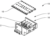
图1示出了在未连接状态下的根据本发明的系统的第一实施例,该系统包括插接接触载体和三个插接接触元件,FIG. 1 shows a first embodiment of a system according to the invention comprising a plug-in contact carrier and three plug-in contact elements in an unconnected state,
图2示出了在插接在一起的状态下的根据本发明的系统的第一实施例,以及Figure 2 shows the first embodiment of the system according to the invention in the plugged together state, and
图3以剖示图示出了图2中呈现的系统,Figure 3 shows the system presented in Figure 2 in a cross-sectional view,
图4示出了直接插接连接器的实施例。Figure 4 shows an embodiment of a direct plug connector.
具体实施方式Detailed ways
在图1中呈现了在未连接状态下的根据本发明的系统1的第一实施例,该系统包括插接接触载体2和三个插接接触元件3。In FIG. 1 a first embodiment of a
插接接触元件3分别具有插口元件4、销钉元件5和插头元件6,该插头元件具有用于经由电路板15的相应接触孔进行直接接触的接触叉。插接接触元件3在接触区域4,5和6之间的区域称为连接区域14。所呈现的插接接触元件3借助于冲压制造。The
插接接触元件3和插接接触载体2如此设计,使得插接接触元件3可以被插入到插接接触载体2中以进行稳定定位。The
为了将插接接触元件3固定在插接接触载体中,插接接触元件3分别具有卡锁元件7,该卡锁元件在插入状态下与对应的卡锁配对元件8在插接接触载体2处形成卡锁连接。卡锁元件7分别布置在插接接触元件的连接区域14中。由此可以确保,卡锁连接例如在不完全卡入的情况下对接触区域没有影响并且就此而言对接触的质量没有影响。In order to fasten the
图2示出了在插接在一起的状态下的图1中呈现的实施例。除了用于固定插接接触元件3的由卡锁元件7和配对卡锁元件8形成的卡锁连接之外,插接接触载体还具有用于每个插接接触元件3的引导元件9,其中,引导元件9不仅使插头元件6的位置稳定而且确保相应的插接接触元件3的笔直插入。FIG. 2 shows the embodiment presented in FIG. 1 in the plugged together state. In addition to the latching connection formed by the latching
在图3中以剖示图示出了图2中呈现的实施例。除了已经描述的部件之外,图3中的图示示出了插接接触元件3具有刚好两个支承面10,插接接触元件3利用所述支承面安放在插接接触载体2上。以这种方式,可以保证在部件之间的尽可能大的自由空间,使得由制造引起的公差对插接接触元件3在插接接触载体2中的位置基本上没有影响。The embodiment presented in FIG. 2 is shown in a cross-sectional view in FIG. 3 . In addition to the components already described, the illustration in FIG. 3 shows that the
此外,插接接触载体2具有用于定位或限制插接接触元件3在插入方向上的运动的止挡面11。插接接触元件3在插入状态下相应利用配对止挡面12贴靠在止挡面11处。Furthermore, the
结果,图1至图3中呈现的由插入到插接接触载体2中的插接接触元件3构成的系统1具有如下优点,即一方面可以由插接接触载体2特别简单地容纳插接接触元件3,并且同时尤其可以通过卡锁连接来确保插接接触元件3在插接接触载体2中的精确定位。As a result, the
图4中呈现了直接插接连接器13的实施例,该直接插接连接器具有图2中所示的由插接接触载体2和布置在插接接触载体2中的插接接触元件3构成的系统1。插接接触载体2布置在壳体的容纳区域16中,其中,容纳区域16通过压配合形状配合且力配合地固定插接接触载体2。此外,还呈现了电路板15,该电路板可以与直接插接连接器13连接。FIG. 4 presents an embodiment of a
附图标记列表List of reference signs
1 由插接接触载体和至少一个插接接触部构成的系统1 System consisting of a plug-in contact carrier and at least one plug-in contact
2 插接接触载体2 Plug contact carrier
3 插接接触部3 Plug contacts
4 接触插口4 Contact socket
5 接触插头5 Contact plug
6 用于与电路板连结的插头6 Plug for connection to circuit board
7 卡锁元件7 locking element
8 配对卡锁元件8 Mating latching elements
9 引导元件9 Guide elements
10 支承面10 Support surface
11 止挡面11 Stop surface
12 配对止挡面12 Mating stop surfaces
13 直接插接连接器13 Direct plug connectors
14 连接面14 Connection surface
15 电路板15 circuit boards
16 容纳区域16 accommodating area
17 壳体。17 Housing.
Claims (11)
Applications Claiming Priority (3)
| Application Number | Priority Date | Filing Date | Title |
|---|---|---|---|
| LU101641A LU101641B1 (en) | 2020-02-13 | 2020-02-13 | System consisting of a plug contact carrier and at least one plug contact element, plug contact carrier, plug contact element and connector |
| LULU101641 | 2020-02-13 | ||
| PCT/EP2021/051795 WO2021160426A1 (en) | 2020-02-13 | 2021-01-27 | System consisting of a plug contact carrier and at least one plug contact element, plug contact carrier, plug contact element, and connector |
Publications (1)
| Publication Number | Publication Date |
|---|---|
| CN115053411A true CN115053411A (en) | 2022-09-13 |
Family
ID=69960680
Family Applications (1)
| Application Number | Title | Priority Date | Filing Date |
|---|---|---|---|
| CN202180014260.2A Pending CN115053411A (en) | 2020-02-13 | 2021-01-27 | System comprising a plug contact carrier and at least one plug contact element, plug contact carrier, plug contact element and plug connector |
Country Status (4)
| Country | Link |
|---|---|
| EP (1) | EP4104251A1 (en) |
| CN (1) | CN115053411A (en) |
| LU (1) | LU101641B1 (en) |
| WO (1) | WO2021160426A1 (en) |
Citations (4)
| Publication number | Priority date | Publication date | Assignee | Title |
|---|---|---|---|---|
| US6050842A (en) * | 1996-09-27 | 2000-04-18 | The Whitaker Corporation | Electrical connector with paired terminals |
| CN102549844A (en) * | 2009-09-21 | 2012-07-04 | 维特电子Ics有限两合公司 | Multi fork press-in pin |
| EP3518347A1 (en) * | 2018-01-25 | 2019-07-31 | Lumberg Connect GmbH | Connector with latching securing hood |
| DE102018112170A1 (en) * | 2018-05-22 | 2019-11-28 | Phoenix Contact Gmbh & Co. Kg | Contact device with a fork |
Family Cites Families (5)
| Publication number | Priority date | Publication date | Assignee | Title |
|---|---|---|---|---|
| US4159158A (en) * | 1977-05-06 | 1979-06-26 | Amp Incorporated | Displation connector having improved terminal supporting means |
| DE19826390C2 (en) * | 1998-06-12 | 2003-11-20 | Whitaker Corp | Electrical contact element |
| DE29907256U1 (en) * | 1999-04-23 | 1999-09-16 | Framatome Connectors Daut + Rietz GmbH, 90411 Nürnberg | Connector for two PCBs |
| DE102013111571B4 (en) | 2013-10-21 | 2016-11-17 | Wago Verwaltungsgesellschaft Mbh | Device housing, electronic devices and plug-in contact carrier |
| DE202016105358U1 (en) | 2016-09-26 | 2018-01-02 | Lumberg Connect Gmbh | Plug contact with insulation displacement fork |
-
2020
- 2020-02-13 LU LU101641A patent/LU101641B1/en active IP Right Grant
-
2021
- 2021-01-27 WO PCT/EP2021/051795 patent/WO2021160426A1/en not_active Ceased
- 2021-01-27 EP EP21701153.5A patent/EP4104251A1/en active Pending
- 2021-01-27 CN CN202180014260.2A patent/CN115053411A/en active Pending
Patent Citations (4)
| Publication number | Priority date | Publication date | Assignee | Title |
|---|---|---|---|---|
| US6050842A (en) * | 1996-09-27 | 2000-04-18 | The Whitaker Corporation | Electrical connector with paired terminals |
| CN102549844A (en) * | 2009-09-21 | 2012-07-04 | 维特电子Ics有限两合公司 | Multi fork press-in pin |
| EP3518347A1 (en) * | 2018-01-25 | 2019-07-31 | Lumberg Connect GmbH | Connector with latching securing hood |
| DE102018112170A1 (en) * | 2018-05-22 | 2019-11-28 | Phoenix Contact Gmbh & Co. Kg | Contact device with a fork |
Also Published As
| Publication number | Publication date |
|---|---|
| EP4104251A1 (en) | 2022-12-21 |
| LU101641B1 (en) | 2021-08-13 |
| WO2021160426A1 (en) | 2021-08-19 |
Similar Documents
| Publication | Publication Date | Title |
|---|---|---|
| US9300064B2 (en) | Connector | |
| CN102959808B (en) | Contact elements for plug-in sockets | |
| JP5825477B2 (en) | Connector | |
| CN110911865B (en) | Electrical connector for circuit board and electrical connector mounting body for circuit board | |
| JP2001006771A (en) | Connector | |
| CN103490203B (en) | The formation method of connector and connector | |
| JPH04233173A (en) | Electric terminal | |
| JP3251849B2 (en) | Shielded connector | |
| JP2012226951A (en) | Electric connector for circuit substrate | |
| CN104218367B (en) | Plug connector and manufacture method thereof | |
| JP2019117693A (en) | Electric connector for circuit board | |
| CN115548723A (en) | Plug strip and method for the production thereof | |
| JP3078520U (en) | Connector device | |
| CN114256651A (en) | Connector with a locking member | |
| JP5827574B2 (en) | Electrical connector with shield plate | |
| US6466452B2 (en) | Socket | |
| CN103608972A (en) | contact element | |
| CN103843204B (en) | Connector and for the manufacture of the method for connector | |
| KR100515993B1 (en) | Contact for electrical connector and electrical connector comprising the same | |
| CN101964462B (en) | Camera module socket | |
| CN115053411A (en) | System comprising a plug contact carrier and at least one plug contact element, plug contact carrier, plug contact element and plug connector | |
| CN100553044C (en) | Connector | |
| CN115039292A (en) | Plug connector, plug contact carrier, housing and method for producing a plug connector | |
| CN211859036U (en) | Electrical housing assembly, electrical connector plug-in structure and thermostat | |
| JP6076953B2 (en) | Board terminal |
Legal Events
| Date | Code | Title | Description |
|---|---|---|---|
| PB01 | Publication | ||
| PB01 | Publication | ||
| SE01 | Entry into force of request for substantive examination | ||
| SE01 | Entry into force of request for substantive examination |