CN108303781B - Camera lens - Google Patents
Camera lens Download PDFInfo
- Publication number
- CN108303781B CN108303781B CN201810133418.8A CN201810133418A CN108303781B CN 108303781 B CN108303781 B CN 108303781B CN 201810133418 A CN201810133418 A CN 201810133418A CN 108303781 B CN108303781 B CN 108303781B
- Authority
- CN
- China
- Prior art keywords
- lens
- imaging
- object side
- curvature
- lenses
- Prior art date
- Legal status (The legal status is an assumption and is not a legal conclusion. Google has not performed a legal analysis and makes no representation as to the accuracy of the status listed.)
- Expired - Fee Related
Links
- 238000003384 imaging method Methods 0.000 claims abstract description 118
- 230000003287 optical effect Effects 0.000 claims abstract description 26
- 239000007788 liquid Substances 0.000 claims 1
- 230000004075 alteration Effects 0.000 description 62
- 238000010586 diagram Methods 0.000 description 28
- 201000009310 astigmatism Diseases 0.000 description 9
- 206010010071 Coma Diseases 0.000 description 8
- 230000000740 bleeding effect Effects 0.000 description 5
- 230000007423 decrease Effects 0.000 description 4
- 239000011521 glass Substances 0.000 description 4
- 239000000463 material Substances 0.000 description 4
- 230000002093 peripheral effect Effects 0.000 description 4
- 238000013461 design Methods 0.000 description 3
- 206010073261 Ovarian theca cell tumour Diseases 0.000 description 2
- 238000012937 correction Methods 0.000 description 2
- 238000011161 development Methods 0.000 description 2
- 238000004519 manufacturing process Methods 0.000 description 2
- 238000000034 method Methods 0.000 description 2
- 230000001681 protective effect Effects 0.000 description 2
- 208000001644 thecoma Diseases 0.000 description 2
- NAWXUBYGYWOOIX-SFHVURJKSA-N (2s)-2-[[4-[2-(2,4-diaminoquinazolin-6-yl)ethyl]benzoyl]amino]-4-methylidenepentanedioic acid Chemical compound C1=CC2=NC(N)=NC(N)=C2C=C1CCC1=CC=C(C(=O)N[C@@H](CC(=C)C(O)=O)C(O)=O)C=C1 NAWXUBYGYWOOIX-SFHVURJKSA-N 0.000 description 1
- 238000001444 catalytic combustion detection Methods 0.000 description 1
- 230000005499 meniscus Effects 0.000 description 1
- 238000012545 processing Methods 0.000 description 1
- 230000002250 progressing effect Effects 0.000 description 1
Images


Classifications
-
- G—PHYSICS
- G02—OPTICS
- G02B—OPTICAL ELEMENTS, SYSTEMS OR APPARATUS
- G02B13/00—Optical objectives specially designed for the purposes specified below
- G02B13/001—Miniaturised objectives for electronic devices, e.g. portable telephones, webcams, PDAs, small digital cameras
- G02B13/0015—Miniaturised objectives for electronic devices, e.g. portable telephones, webcams, PDAs, small digital cameras characterised by the lens design
- G02B13/002—Miniaturised objectives for electronic devices, e.g. portable telephones, webcams, PDAs, small digital cameras characterised by the lens design having at least one aspherical surface
- G02B13/0045—Miniaturised objectives for electronic devices, e.g. portable telephones, webcams, PDAs, small digital cameras characterised by the lens design having at least one aspherical surface having five or more lenses
-
- G—PHYSICS
- G02—OPTICS
- G02B—OPTICAL ELEMENTS, SYSTEMS OR APPARATUS
- G02B13/00—Optical objectives specially designed for the purposes specified below
- G02B13/06—Panoramic objectives; So-called "sky lenses" including panoramic objectives having reflecting surfaces
-
- G—PHYSICS
- G02—OPTICS
- G02B—OPTICAL ELEMENTS, SYSTEMS OR APPARATUS
- G02B27/00—Optical systems or apparatus not provided for by any of the groups G02B1/00 - G02B26/00, G02B30/00
- G02B27/0025—Optical systems or apparatus not provided for by any of the groups G02B1/00 - G02B26/00, G02B30/00 for optical correction, e.g. distorsion, aberration
-
- G—PHYSICS
- G02—OPTICS
- G02B—OPTICAL ELEMENTS, SYSTEMS OR APPARATUS
- G02B3/00—Simple or compound lenses
- G02B3/0087—Simple or compound lenses with index gradient
-
- G—PHYSICS
- G02—OPTICS
- G02B—OPTICAL ELEMENTS, SYSTEMS OR APPARATUS
- G02B9/00—Optical objectives characterised both by the number of the components and their arrangements according to their sign, i.e. + or -
- G02B9/60—Optical objectives characterised both by the number of the components and their arrangements according to their sign, i.e. + or - having five components only
Landscapes
- Physics & Mathematics (AREA)
- General Physics & Mathematics (AREA)
- Optics & Photonics (AREA)
- Lenses (AREA)
Abstract
本发明提供由具有优秀的光学特性,小型、而且镜头后焦长、视场角为80°以上、具有2.40以下明亮的F值的5个透镜构成的摄像镜头。该摄像镜头从物体侧开始依次配置有:具有负屈折力的第1透镜、具有正屈折力的第2透镜、光圈、具有负屈折力的第3透镜、具有正屈折力的第4透镜、具有负屈折力的第5透镜,并且满足规定的条件公式。本发明尤其适用可手机摄影镜头、移动设备摄影镜头、机器人相机镜头、车载镜头、工业相机镜头等小型相机。
The present invention provides an imaging lens composed of five lenses having excellent optical properties, being compact, having a lens back focal length, a field angle of 80° or more, and a bright F value of 2.40 or less. The imaging lens includes, in order from the object side, a first lens having a negative refractive power, a second lens having a positive refractive power, an aperture, a third lens having a negative refractive power, a fourth lens having a positive refractive power, and a The 5th lens with negative refractive power, and satisfies the specified conditional formula. The invention is especially suitable for small cameras such as mobile phone photography lenses, mobile device photography lenses, robot camera lenses, vehicle-mounted lenses, industrial camera lenses and the like.
Description
技术领域technical field
本发明是涉及由具有优秀的光学特性,小型、而且镜头后焦长、视场角为80°以上、具有2.40以下明亮的F值的5个透镜构成的,可用于手机摄影镜头、移动设备摄影镜头、机器人相机镜头、车载镜头、工业相机镜头等小型相机的摄像镜头。The present invention relates to five lenses with excellent optical properties, small size, lens back focal length, field angle of 80° or more, and a bright F value of 2.40 or less, which can be used for mobile phone photography lenses and mobile device photography. Camera lens for small cameras such as lens, robot camera lens, vehicle lens, industrial camera lens, etc.
背景技术Background technique
近年,使用CCD和CMOS等摄像元件的各种摄像装置广泛普及起来。随着摄像元件小型化、高性能化发展,社会更需求具有优秀的光学特性的小型摄像镜头。In recent years, various imaging devices using imaging elements such as CCDs and CMOSs have become widespread. With the development of miniaturization and high performance of imaging elements, the society demands more compact imaging lenses with excellent optical properties.
与由小型且具有优秀的光学特性的5个透镜构成的摄像镜头相关的技术开发正在逐步推进。提出方案为摄像镜头由5个透镜构成,从物侧开始依次是负屈折力的第1透镜、正屈折力的第2透镜、负屈折力的第3透镜、正屈折力的第4透镜、负屈折力的第5透镜。Technological development related to an imaging lens composed of five lenses that are small and have excellent optical properties is progressing step by step. The proposed solution is that the imaging lens consists of 5 lenses, which are the first lens with negative refractive power, the second lens with positive refractive power, the third lens with negative refractive power, the fourth lens with positive refractive power, and the negative refractive power from the object side. 5th lens of refractive power.
相关技术的摄像镜头由上述5个透镜构成,虽然在第1透镜与第2 透镜之间设置了光圈,但是因为超薄和长镜头后焦的要求,第1透镜与第2透镜间隔会变窄,很难确保放入光圈的空间。而且,无法将第1 透镜边缘部直接对准第2透镜边缘部,因为需要放入光圈部材,所以存在公差上的问题。The imaging lens of the related art is composed of the above-mentioned five lenses. Although an aperture is set between the first lens and the second lens, the distance between the first lens and the second lens will be narrowed due to the requirements of ultra-thin and long back focus. , it is difficult to secure space for the aperture. Furthermore, since it is impossible to directly align the edge portion of the first lens with the edge portion of the second lens, since it is necessary to put the diaphragm member, there is a problem in tolerance.
而且,Fno光线宽广的第3透镜近轴上的摄像侧面向凹的凹凸透镜较弱,所以彗形像差会变大,所以存在当变成比F2.4更亮时轴上附近的分辨率会下降的问题。In addition, the third lens with wide Fno light has a weak paraxial concave meniscus lens on the paraxial side, so the coma aberration increases, so there is a resolution near the axis when it becomes brighter than F2.4 problem will drop.
相关技术的摄像镜头由上述5个透镜构成,虽然通过在第2透镜与第3透镜之间设置光圈,解决了上述问题,但是在像侧由于凸形状的第 3透镜而发生轴上附近的慧形像差,当设为2.4以下明亮的F值时,轴上附近的分辨率会下降。而且,虽然第3透镜的阿贝为0以上,但是很难消除轴上色差,当设为2.4以下明亮的F值时,轴上附近的分辨率会下降,无法支持近来的高像素化要求。The imaging lens of the related art is composed of the above-mentioned five lenses, and although the above-mentioned problem is solved by providing a diaphragm between the second lens and the third lens, the third lens having a convex shape on the image side causes an in-axis near the axis. Aberration, when set to a bright F value of 2.4 or less, the resolution near the axis will drop. In addition, although the Abbe of the third lens is 0 or more, it is difficult to eliminate the axial chromatic aberration, and when the F value is set to a bright F value of 2.4 or less, the resolution near the axis will drop, and it cannot support the recent demand for high pixelation.
发明内容SUMMARY OF THE INVENTION
本发明的目的是提供由具有优秀的光学特性,小型、而且镜头后焦长、视场角为80°以上、具有2.4以下明亮的F值的5个透镜构成的,可用于手机摄影镜头、移动设备摄影镜头、机器人相机镜头、车载镜头、工业相机镜头等小型相机的摄像镜头。The object of the present invention is to provide five lenses that have excellent optical properties, are small, have a lens back focal length, a field angle of 80° or more, and have a bright F value of 2.4 or less, which can be used as a mobile phone camera lens, mobile Camera lens for small cameras such as equipment photography lens, robot camera lens, vehicle lens, industrial camera lens, etc.
为达成上述目标,在对透镜的屈折力分配,从像侧面到物侧面的轴上距离与摄像镜头整体的焦距之比、透镜的形状进行认真研讨后,提出改善以往技术的摄像镜头方案,于是形成本发明。In order to achieve the above goals, after careful consideration of the distribution of the refractive power of the lens, the ratio of the on-axis distance from the image side to the object side to the overall focal length of the imaging lens, and the shape of the lens, an imaging lens scheme that improves the conventional technology is proposed. form the present invention.
根据上述需解决的技术问题,在从物侧到摄像侧依次为“负正负正负”5个透镜构成的摄像镜头以及使用该摄像镜头的相机系统中,光圈位于第2透镜与第3透镜之间,According to the above technical problems to be solved, in an imaging lens composed of five lenses "negative, positive, negative, positive and negative" in order from the object side to the imaging side, and a camera system using the imaging lens, the apertures are located in the second lens and the third lens. between,
第1透镜的物侧面在近轴上为凸面,The object side of the first lens is convex on the paraxial surface,
第2透镜的物侧面在近轴上为凸面,The object side of the second lens is convex on the paraxial surface,
第3透镜的像侧面在近轴上为凹面,The image side surface of the third lens is concave on the paraxial surface,
第4透镜的物侧面在近轴上为凹面,The object side of the fourth lens is concave on the paraxial surface,
第4透镜的像侧面在近轴上为凸面,The image side of the fourth lens is convex in the paraxial direction,
第5透镜的物侧面在近轴上为凸面,The object side of the fifth lens is convex on the paraxial surface,
第5透镜的像侧面在近轴上为凹面,The image side of the fifth lens is concave on the paraxial surface,
至少,At least,
第1透镜的物侧面、第3透镜的物侧面、第3透镜的摄像侧面、第 4透镜的物侧面、第4透镜的摄像侧面、第5透镜的物侧面、第5透镜的摄像侧面具有非球面并满足下列条件公式(1)-(4):The object side of the first lens, the object side of the third lens, the imaging side of the third lens, the object side of the fourth lens, the imaging side of the fourth lens, the object side of the fifth lens, the imaging side of the fifth lens have non- sphere and satisfy the following conditional formulas (1)-(4):
-550≤f1/f2≤-2.5 (1)-550≤f1/f2≤-2.5 (1)
0.1≤T23/f≤0.2 (2)0.1≤T23/f≤0.2 (2)
-86.3≤R31/f3≤6.3 (3)-86.3≤R31/f3≤6.3 (3)
-2.0≤R32/f3≤-0.3 (4)-2.0≤R32/f3≤-0.3 (4)
其中,in,
f1:第1透镜的焦距;f1: the focal length of the first lens;
f2:第2透镜的焦距;f2: the focal length of the second lens;
f3:第3透镜的焦距;f3: the focal length of the third lens;
f:摄像镜头整体的焦距;f: the focal length of the camera lens as a whole;
T23:第2透镜与第3透镜之间的光轴上的空气间隔;T23: the air space on the optical axis between the second lens and the third lens;
R31:第3透镜物侧面的曲率;R31: curvature of the object side of the third lens;
R32:第3透镜摄像侧面的曲率。R32: The curvature of the imaging side surface of the third lens.
优选的,所述的摄像镜头满足下列条件公式(5)-(8):Preferably, the camera lens satisfies the following conditional formulas (5)-(8):
15≤V1≤23.7 (5)15≤V1≤23.7 (5)
15≤V3≤23.1 (6)15≤V3≤23.1 (6)
V2>V3 (7)V2>V3 (7)
34.5≤V2-V1≤55.3 (8)34.5≤V2-V1≤55.3 (8)
其中,in,
V1:第1透镜的阿贝数;V1: Abbe number of the first lens;
V2:第2透镜的阿贝数;V2: Abbe number of the second lens;
V3:第3透镜的阿贝数。V3: Abbe number of the third lens.
优选的,所述的摄像镜头第3透镜的摄像侧面,自光轴向周边,由凹面变为凸面。Preferably, the imaging side surface of the third lens of the imaging lens changes from a concave surface to a convex surface from the periphery of the optical axis.
优选的,所述的摄像镜头满足下列条件公式(11):Preferably, the camera lens satisfies the following conditional formula (11):
2.0<|R32-R41|/|R41|<12.0 (11)2.0<|R32-R41|/|R41|<12.0 (11)
其中,in,
R32:第3透镜摄像侧面的曲率;R32: The curvature of the imaging side of the third lens;
R41:第4透镜物侧面的曲率。R41: Curvature of the object side surface of the fourth lens.
优选的,所述的摄像镜头第4透镜的摄像侧面,自光轴向周边,由凸面变为凹面,并满足下列条件公式(12):Preferably, the imaging side surface of the fourth lens of the imaging lens changes from a convex surface to a concave surface from the periphery of the optical axis, and satisfies the following conditional formula (12):
0.35<|R42|/f4<0.48 (12)0.35<|R42|/f4<0.48 (12)
其中,in,
R42:第4透镜摄像侧面的曲率;R42: curvature of the imaging side of the fourth lens;
f4:第4透镜的焦距。f4: The focal length of the 4th lens.
优选的,所述的摄像镜头第1透镜的物侧面,自光轴向周边,由凸面变为凹面。Preferably, the object side surface of the first lens of the imaging lens changes from a convex surface to a concave surface from the periphery of the optical axis.
优选的,所述的摄像镜头,其特征在于,满足下列条件公式(13):Preferably, the camera lens is characterized in that it satisfies the following conditional formula (13):
0.6<f12/f<1.9 (13)0.6<f12/f<1.9 (13)
其中,in,
f12:第1透镜与第2的合成焦距。f12: The combined focal length of the first lens and the second lens.
附图说明Description of drawings
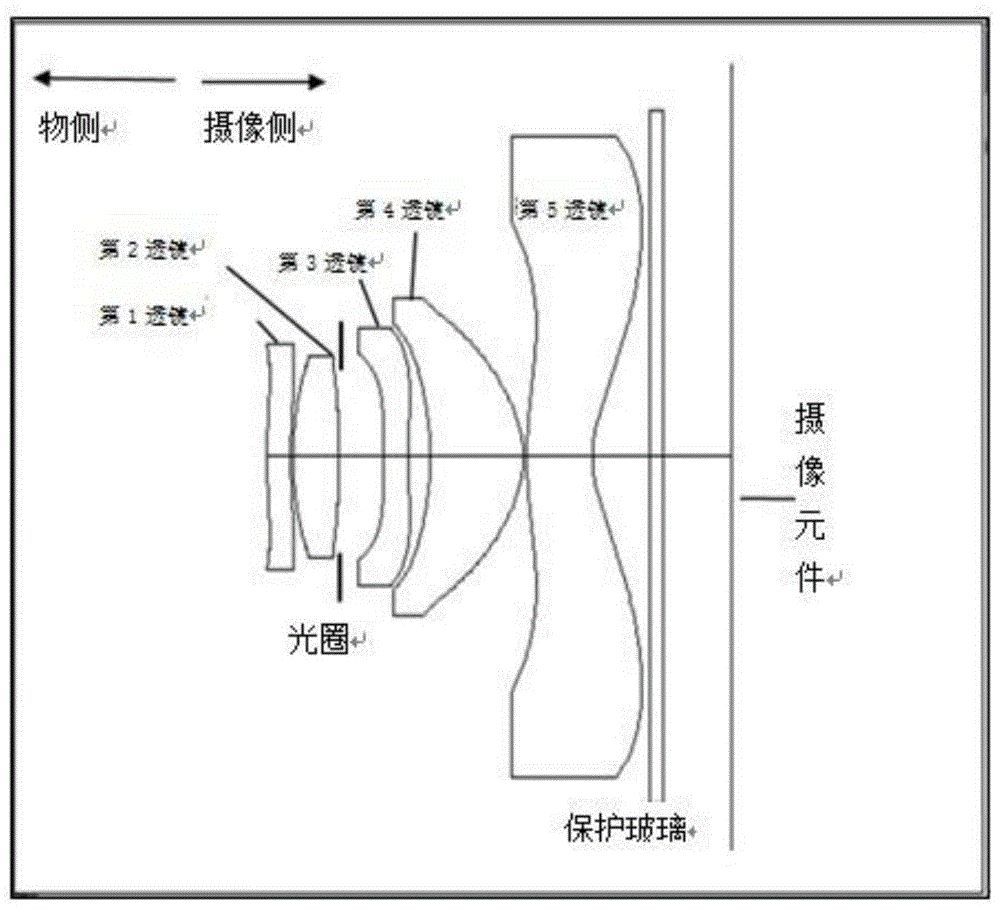
图1是与本发明一种实施方式相关的摄像镜头LA的构成展示图。FIG. 1 is a diagram showing the configuration of an imaging lens LA according to an embodiment of the present invention.
图2是与本发明一种实施方式相关的摄像镜头LS的光路图。FIG. 2 is an optical path diagram of the imaging lens LS according to an embodiment of the present invention.
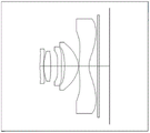
图3是上述摄像镜头LA的具体实例1的构成展示图。FIG. 3 is a diagram showing the configuration of the specific example 1 of the above-mentioned imaging lens LA.
图4是实例1中摄像镜头LA的轴向像差展示图。FIG. 4 is a diagram showing the axial aberration of the imaging lens LA in Example 1. FIG.
图5是实例1中摄像镜头LA的场曲和畸变展示图。FIG. 5 is a diagram showing field curvature and distortion of the imaging lens LA in Example 1. FIG.
图6是实例1中摄像镜头LA的倍率色差展示图。FIG. 6 is a diagram showing the magnification chromatic aberration of the imaging lens LA in Example 1. FIG.
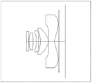
图7是上述摄像镜头LA的具体实例2的构成展示图。FIG. 7 is a diagram showing the configuration of a specific example 2 of the above-mentioned imaging lens LA.
图8是实例2中摄像镜头LA的轴向像差展示图。FIG. 8 is a diagram showing the axial aberration of the imaging lens LA in Example 2. FIG.
图9是实例2中摄像镜头LA的场曲和畸变展示图。FIG. 9 is a diagram showing field curvature and distortion of the imaging lens LA in Example 2. FIG.
图10是实例2中摄像镜头LA的倍率色差展示图。FIG. 10 is a diagram showing the chromatic aberration of magnification of the imaging lens LA in Example 2. FIG.
图11是上述摄像镜头LA的具体实例3的构成展示图。FIG. 11 is a diagram showing the configuration of a specific example 3 of the above-mentioned imaging lens LA.
图12是实例3中摄像镜头LA的轴向像差展示图。12 is a diagram showing the axial aberration of the imaging lens LA in Example 3. FIG.
图13是实例3中摄像镜头LA的场曲和畸变展示图。FIG. 13 is a diagram showing field curvature and distortion of the imaging lens LA in Example 3. FIG.
图14是实例3中摄像镜头LA的倍率色差展示图。FIG. 14 is a diagram showing the magnification chromatic aberration of the imaging lens LA in Example 3. FIG.
图15是上述摄像镜头LA的具体实例4的构成展示图。FIG. 15 is a diagram showing the configuration of a specific example 4 of the above-mentioned imaging lens LA.
图16是实例4中摄像镜头LA的轴向像差展示图。16 is a diagram showing the axial aberration of the imaging lens LA in Example 4. FIG.
图17是实例4中摄像镜头LA的场曲和畸变展示图。17 is a diagram showing field curvature and distortion of the imaging lens LA in Example 4. FIG.
图18是实例4中摄像镜头LA的倍率色差展示图。FIG. 18 is a diagram showing the chromatic aberration of magnification of the imaging lens LA in Example 4. FIG.
图19是上述摄像镜头LA的具体实例5的构成展示图。FIG. 19 is a diagram showing the configuration of a specific example 5 of the above-described imaging lens LA.
图20是实例5中摄像镜头LA的轴向像差展示图。20 is a diagram showing the axial aberration of the imaging lens LA in Example 5. FIG.
图21 是实例5中摄像镜头LA的场曲和畸变展示图。FIG. 21 is a diagram showing field curvature and distortion of the imaging lens LA in Example 5. FIG.
图22是实例5中摄像镜头LA的倍率色差展示图。FIG. 22 is a diagram showing the magnification chromatic aberration of the imaging lens LA in Example 5. FIG.
具体实施方式Detailed ways
参考附图来说明与本发明相关的摄像镜头的一种实施方式。图1 示出与本发明一实施方式相关的摄像镜头的构成图。该摄像镜头LA是由5个透镜群构成,从物侧到摄像侧依次配置第1透镜、第2透镜、光圈、第3透镜、第4透镜、第5透镜。在第5透镜与摄像面之间设置保护玻璃。保护玻璃可以为1块以上也可以不设置。One embodiment of the imaging lens related to the present invention will be described with reference to the accompanying drawings. FIG. 1 shows a configuration diagram of an imaging lens according to an embodiment of the present invention. The imaging lens LA is composed of five lens groups, and a first lens, a second lens, a diaphragm, a third lens, a fourth lens, and a fifth lens are arranged in this order from the object side to the imaging side. A protective glass is provided between the fifth lens and the imaging surface. One or more pieces of protective glass may or may not be provided.
本发明通过由从物侧到摄像侧依次为负正负正负的5个透镜构成,可以得到系统总长短、镜头后焦长的镜头。The present invention is composed of 5 lenses that are negative, positive, negative, and negative in sequence from the object side to the imaging side, so that the lens with the total length of the system and the rear focal length of the lens can be obtained.
通过光圈位于第2透镜与第3透镜之间,在加工上、公差上可以得到正常的镜框设计,最终可以提高量产成品率与量产性。By positioning the aperture between the second lens and the third lens, a normal frame design can be obtained in terms of processing and tolerance, and ultimately, the mass production yield and mass production can be improved.
第1透镜的物侧面近轴上朝物侧有凸面,第2透镜的物侧面近轴上朝物侧有凸面,第3透镜的摄像侧面近轴上朝摄像侧有凹面,第4透镜的物侧面近轴上朝物侧有凹面,第4透镜的摄像侧面近轴上朝摄像侧有凸面,第5透镜的物侧面近轴上朝物侧有凸面,第5透镜的摄像侧面近轴上朝摄像侧有凹面,至少,第1透镜的物侧面、第3透镜的物侧面、第3透镜的摄像侧面、第4透镜的物侧面、第4透镜的摄像侧面、第5 透镜的物侧面、第5透镜的摄像侧面具有非球面,设计为Fno明亮,视场角宽广的规格,可以提高分辨率。The object side of the first lens has a convex surface paraxially facing the object side, the object side of the second lens has a convex surface paraxially facing the object side, the imaging side of the third lens has a concave surface paraxially facing the imaging side, and the object side of the fourth lens has a concave surface on the paraxial side. There is a concave surface on the side paraxial to the object side, the imaging side of the 4th lens has a convex surface paraxially facing the imaging side, the object side of the 5th lens has a convex surface paraxially facing the object side, and the imaging side of the 5th lens has a paraxial surface facing the object side. The imaging side has a concave surface, at least the object side of the first lens, the object side of the third lens, the imaging side of the third lens, the object side of the fourth lens, the imaging side of the fourth lens, the object side of the fifth lens, the The camera side of the 5-lens has an aspherical surface and is designed to have a bright Fno and a wide field of view to improve resolution.
该摄像镜头LA是满足下列条件公式(1)-(4)的摄像镜头:The camera lens LA is a camera lens that satisfies the following conditional formulas (1)-(4):
-550≤f1/f2≤-2.5 (1)-550≤f1/f2≤-2.5 (1)
0.1≤T23/f≤0.2 (2)0.1≤T23/f≤0.2 (2)
-86.3≤R31/f3≤6.3 (3)-86.3≤R31/f3≤6.3 (3)
-2.0≤R32/f3≤-0.3 (4)-2.0≤R32/f3≤-0.3 (4)
其中,in,
f1:第1透镜的焦距;f1: the focal length of the first lens;
f2:第2透镜的焦距;f2: the focal length of the second lens;
f3:第3透镜的焦距;f3: the focal length of the third lens;
f:摄像镜头整体的焦距;f: the focal length of the camera lens as a whole;
T23:第2透镜与第3透镜之间的光轴上的空气间隔;T23: the air space on the optical axis between the second lens and the third lens;
R31:第3透镜物侧面的曲率;R31: curvature of the object side of the third lens;
R32:第3透镜摄像侧面的曲率。R32: The curvature of the imaging side surface of the third lens.
条件公式(1)是镜头后焦与光学全长的公式。当超过条件公式上限时,第1透镜负屈折力变强,光学全长变长,规格上不适合。当低于条件公式下限时,第1透镜负屈折力变弱,镜头后焦变短,规格上不适合。Conditional formula (1) is the formula of the lens back focus and the optical total length. If the upper limit of the conditional formula is exceeded, the negative refractive power of the first lens becomes stronger, and the optical total length becomes longer, which is not suitable for the specification. If it is lower than the lower limit of the conditional formula, the negative refractive power of the first lens becomes weak, and the back focus of the lens becomes shorter, which is not suitable for the specification.
条件公式(2)是光圈空间与轴上的分辨公式。当超过条件公式上限时,入射到第3透镜的Fno光束会变细,轴向像差或色差变得补正不足,轴向像差与轴上色差出现恶化,结果导致轴上分辨性能下降。当低于条件公式下限时,光圈部材的空间会变窄,加工上、镜框设计上会变得困难。Conditional formula (2) is a resolution formula between the aperture space and the axis. When the upper limit of the conditional formula is exceeded, the Fno beam incident on the third lens becomes thinner, the axial aberration or chromatic aberration becomes insufficiently corrected, and the axial aberration and axial chromatic aberration deteriorate, resulting in a decrease in on-axis resolution performance. When the lower limit of the conditional formula is lower than the lower limit of the conditional formula, the space for the aperture member becomes narrow, making it difficult to process and design the lens frame.
条件公式(3)是控制因Fno明亮产生的轴向像差、慧形像差增大,改善轴上与中间像高的分辨性能的公式。当超过条件公式上限时,面周边部与光圈不同轴的情况下,对以像散为首的受视场角影响的像差会增大,周边像高的分辨性能会恶化。当低于条件公式下限时,由于轴向像差、慧形像差增大,轴上与中间像高的分辨性能会恶化。Conditional formula (3) is a formula for controlling the increase of axial aberration and coma aberration caused by the brightness of Fno, and improving the resolution performance of the on-axis and intermediate image heights. When the upper limit of the conditional formula is exceeded, when the peripheral surface of the surface is not coaxial with the aperture, the aberrations affected by the viewing angle including astigmatism will increase, and the resolution performance of the peripheral image height will deteriorate. When it is lower than the lower limit of the conditional formula, the resolution performance of on-axis and intermediate image heights will deteriorate due to the increase of axial aberration and coma aberration.
条件公式(4)是控制因Fno明亮产生的轴向像差、慧形像差增大,确保轴上与中间像高的分辨性能的公式。当超过条件公式上限时,面周边部与光圈不同轴的情况下,对以像散为首的受视场角影响的像差会增大,周边像高的分辨性能会恶化。当低于条件公式下限时,由于轴向像差、慧形像差增大,轴上与中间像高的分辨性能会恶化。Conditional formula (4) is a formula for controlling the increase of axial aberration and coma aberration due to the brightness of Fno, and ensuring the resolution performance of on-axis and intermediate image heights. When the upper limit of the conditional formula is exceeded, when the peripheral surface and the aperture are not coaxial, the aberrations affected by the field angle including astigmatism will increase, and the resolution performance of the peripheral image height will deteriorate. When it is lower than the lower limit of the conditional formula, the resolution performance of on-axis and intermediate image heights will deteriorate due to the increase of axial aberration and coma aberration.
15≤V1≤23.7 (5)15≤V1≤23.7 (5)
15≤V3≤23.1 (6)15≤V3≤23.1 (6)
V2>V3 (7)V2>V3 (7)
34.5≤V2-V1≤55.3 (8)34.5≤V2-V1≤55.3 (8)
其中,in,
V1:第1透镜的阿贝数;V1: Abbe number of the first lens;
V2:第2透镜的阿贝;V2: Abbe of the 2nd lens;
V3:第3透镜的阿贝数。V3: Abbe number of the third lens.
条件公式(5)是消除轴上与轴外色差的公式。在条件公式范围外,轴上色差、倍率色差的改善变得很困难,会发生渗色,规格上不适合。Conditional formula (5) is a formula for eliminating on-axis and off-axis chromatic aberration. Outside the range of the conditional formula, it is difficult to improve the axial chromatic aberration and the chromatic aberration of magnification, and color bleeding occurs, which is not suitable for the specification.
条件公式(6)是消除轴上与轴外色差的公式。在条件公式范围外,轴上色差、倍率色差的改善变得很困难,会发生渗色,规格上不适合。Conditional formula (6) is a formula for eliminating on-axis and off-axis chromatic aberration. Outside the range of the conditional formula, it is difficult to improve the axial chromatic aberration and the chromatic aberration of magnification, and color bleeding occurs, which is not suitable for the specification.
条件公式(7)是消除轴上与轴外色差的公式。在条件公式范围外,轴上色差、倍率色差的改善变得很困难,会发生渗色。Conditional formula (7) is a formula for eliminating on-axis and off-axis chromatic aberration. Outside the range of the conditional formula, it becomes difficult to improve the axial chromatic aberration and the chromatic aberration of magnification, and bleeding occurs.
条件公式(8)是消除轴上与轴外色差的公式。在条件公式范围外,轴上色差、倍率色差的改善变得很困难,会发生渗色。Conditional formula (8) is a formula for eliminating on-axis and off-axis chromatic aberration. Outside the range of the conditional formula, it becomes difficult to improve the axial chromatic aberration and the chromatic aberration of magnification, and bleeding occurs.
-86.3≤R31/f3≤0.0 (9)-86.3≤R31/f3≤0.0 (9)
35.5≤V2-V1≤44.2 (10)35.5≤V2-V1≤44.2 (10)
其中,in,
R31:第3透镜物侧面的曲率;R31: curvature of the object side of the third lens;
f3:第3透镜的焦距。f3: The focal length of the third lens.
条件公式(9)是将条件公式(3)的范围缩小,并进行了高分辨化的。而且,可以得到分辨性能良好的镜头。Conditional formula (9) narrows the range of conditional formula (3), and performs high resolution. Furthermore, a lens with good resolution performance can be obtained.
条件公式(10)是将条件公式(8)的范围缩小,并对轴外与轴上色差进行了改善的。而且,可以得到渗色很少的镜头。Conditional formula (10) narrows the range of conditional formula (8) and improves off-axis and on-axis chromatic aberration. Also, a lens with very little color bleeding can be obtained.
其特征在于,本发明的第3透镜的摄像侧面,靠近光轴的部位面向外面,从摄像侧来看,呈现从凹往凸变化。为了改善轴上慧形像差,朝摄像侧最好是凹面,但是对于以像散为首的受视场角影响的像差来说,朝摄像侧最好是凸面。本发明的第3透镜摄像侧面,因为轴上光束与轴外光束没有完全重合,在非球面通过“从摄像侧来看,呈现从凹往凸变化”,补正了矛盾的要素。It is characterized in that the imaging side surface of the third lens of the present invention faces outward at a portion close to the optical axis, and changes from concave to convex when viewed from the imaging side. In order to improve the on-axis coma aberration, a concave surface is preferable toward the imaging side, but a convex surface toward the imaging side is preferable for aberrations affected by the angle of view including astigmatism. In the imaging side of the third lens of the present invention, because the on-axis light beam and the off-axis light beam do not completely overlap, the aspheric surface corrects the conflicting elements by "seeing from the imaging side, showing a change from concave to convex".
2.0<|R32-R41|/|R41|<12.0 (11)2.0<|R32-R41|/|R41|<12.0 (11)
其中,in,
R32:第3透镜摄像侧面的曲率;R32: curvature of the imaging side of the third lens;
R41:第4透镜物侧面的曲率。R41: Curvature of the object side surface of the fourth lens.
条件公式(11)是像散与轴上和中间像高的慧形像差的公式。当超过条件公式上限时,像散出现恶化,轴上分辨下降。当低于条件公式下限时,轴上和中间像高慧形像差出现恶化,从轴上到中间像高的分辨下降。Conditional formula (11) is a formula for astigmatism and coma aberration of the axial and intermediate image heights. When the upper limit of the conditional formula is exceeded, the astigmatism deteriorates and the on-axis resolution decreases. When the lower limit of the conditional formula is exceeded, the coma aberration of the on-axis and intermediate image heights deteriorates, and the resolution from the on-axis to the intermediate image height decreases.
其特征在于,本发明的第4透镜的摄像侧面,靠近光轴的部位面向外面,从摄像侧来看,呈现从凸往凹变化。对于以像散为首的受视场角影响的像差来说,朝摄像侧最好凸面,轴外慧形像差补正朝摄像侧最好凹面。本发明的第4透镜摄像侧面,因为上侧光束与主光线没有完全重合,在非球面通过“从摄像侧来看,呈现从凸往凹变化”,补正了矛盾的要素。It is characterized in that the imaging side surface of the fourth lens of the present invention faces outward at a portion close to the optical axis, and changes from convexity to concave when viewed from the imaging side. For aberrations such as astigmatism and other aberrations that are affected by the angle of view, a convex surface is preferable to the imaging side, and a concave surface is preferable to the imaging side for correction of off-axis coma aberration. In the imaging side of the fourth lens of the present invention, since the upper light beam and the chief ray do not completely overlap, the aspheric surface corrects the conflicting elements by "viewing from the imaging side, showing a change from convex to concave".
0.35<|R42|/f4<0.48 (12)0.35<|R42|/f4<0.48 (12)
其中,in,
R42:第4透镜摄像侧面的曲率;R42: curvature of the imaging side of the fourth lens;
f4:第4透镜的焦距。f4: The focal length of the 4th lens.
条件公式(12)是对以像散为首的受视场角影响的像差进行补正的公式。通过满足条件公式(12)的公式,可以对以像散为首的受视场角影响的像差进行补正,可以提高轴外分辨性能。Conditional formula (12) is a formula for compensating aberrations affected by the viewing angle including astigmatism. By satisfying the formula of the conditional formula (12), the aberrations affected by the viewing angle including astigmatism can be corrected, and the off-axis resolution performance can be improved.
其特征在于,本发明的第1透镜的物侧面,靠近光轴的部位面向外面,从摄像侧来看,呈现从凸往凹变化。对于以像散为首的受视场角影响的像差来说,朝物侧最好凸面,轴外慧形像差补正朝摄像侧最好凹面。本发明的第1透镜摄像侧面,因为与下侧光束的偏离,在通过非球面“从摄像侧来看,呈现从凸往凹变化”,补正了矛盾的要素。It is characterized in that the object side surface of the first lens of the present invention faces outward at a portion close to the optical axis, and changes from convex to concave when viewed from the imaging side. For aberrations that are affected by the angle of view, including astigmatism, a convex surface is preferable to the object side, and a concave surface is preferable to the imaging side for correction of off-axis coma aberration. The imaging side of the first lens of the present invention, due to the deviation from the lower beam, "appears from convexity to concave when viewed from the imaging side" through the aspherical surface, thereby correcting the conflicting elements.
0.6<f12/f<1.9 (13)0.6<f12/f<1.9 (13)
其中,in,
f12:第1透镜与第2的合成焦距。f12: The combined focal length of the first lens and the second lens.
条件公式(13)是光学全长与分辨性能的公式。当低于条件公式下限时,光学全长会延长,规格上不合适。当超过条件公式上限时,透镜的各自屈折力会变大,各种像差会增大,分辨性能会下降,规格上不合适。Conditional formula (13) is a formula for the optical total length and the resolution performance. When it falls below the lower limit of the conditional formula, the overall optical length will be extended, and the specification will not be suitable. When the upper limit of the conditional formula is exceeded, the respective refractive power of the lens will increase, various aberrations will increase, the resolution performance will decrease, and the specification will not be suitable.
下面关于本发明的摄像镜头,采用实例进行说明。各实例中所记载的符号具体表示如下:距离、半径与中心厚度的单位为mm。Hereinafter, the imaging lens of the present invention will be described using an example. The symbols described in each example are specifically expressed as follows: the unit of distance, radius and center thickness is mm.
f:摄像镜头整体的焦距;f: the focal length of the camera lens as a whole;
Fno:F值;Fno: F value;
2ω:视场角;2ω: field of view;
R:光学面的曲率半径、透镜时为中心曲率半径;R: the radius of curvature of the optical surface, the central radius of curvature in the case of a lens;
R1:物侧面的曲率半径;R1: the radius of curvature of the side of the object;
R2:摄像侧面的曲率半径;R2: the radius of curvature of the camera side;
D:透镜的中心厚度或者透镜之间的距离;D: the center thickness of the lens or the distance between the lenses;
nd:透镜材料的d线的折射率;nd: the refractive index of the d-line of the lens material;
vd:透镜材料的阿贝数;vd: Abbe number of the lens material;
TL:光学长度(从第1透镜的物侧面到像面的轴上距离);TL: optical length (the on-axis distance from the object side of the first lens to the image plane);
BF:从第1透镜的摄像侧面到高斯像面的轴上距离;BF: the on-axis distance from the imaging side of the first lens to the Gaussian image plane;
(玻璃平板GF的厚度除外)(Except thickness of glass plate GF)
Y:最大像高。Y: Maximum image height.
y=(x2/R)/[1+{1-(k+1)(x2/R2)}1/2]+A4x4+A6x6+A8x8+A10x10+A1 2x12+A14x14+A16x16 (14)y=(x2/R)/[1+{1-(k+1)(x2/R2)}1/2]+A4x4+A6x6+A8x8+A10x10+A1 2x12+A14x14+A16x16 (14)
其中,R是轴上的曲率半径,k是圆锥系数,A4、A6、A8、A10、 A12、A14、A16是非球面系数。where R is the radius of curvature on the axis, k is the conic coefficient, and A4, A6, A8, A10, A12, A14, and A16 are the aspheric coefficients.
为方便起见,各个透镜面的非球面使用公式(14)中所示的非球面。但是,本发明不限于该公式(14)表示的非球面多项式。For the sake of convenience, the aspherical surface shown in the formula (14) is used as the aspherical surface of each lens surface. However, the present invention is not limited to the aspheric polynomial represented by the formula (14).
(实例1)(Example 1)
图3是实例1中摄像镜头LA的配置构成图。表1的数据有:实例 1中构成摄像镜头LA的第1透镜~第5透镜的物侧的曲率半径R1、摄像侧的曲率半径R2、透镜中心厚度或透镜间的距离D、折射率nd、阿贝数vd。表2中的数据有:圆锥系数k、非球面系数。FIG. 3 is a configuration configuration diagram of the imaging lens LA in Example 1. FIG. The data in Table 1 are: the curvature radius R1 on the object side of the first to fifth lenses constituting the imaging lens LA in Example 1, the curvature radius R2 on the imaging side, the thickness of the center of the lens or the distance D between the lenses, the refractive index nd, Abbe number vd. The data in Table 2 are: cone coefficient k, aspheric coefficient.
【表1】【Table 1】

【表2】【Table 2】

表11示出实例1、2、3、4、5中各种数值与条件公式(1)~(13)中已规定的参数所对应的值。实例1、2、3、4、5的设计基准波长为555nm。Table 11 shows the values corresponding to various numerical values in Examples 1, 2, 3, 4, and 5 and the parameters specified in the conditional formulae (1) to (13). The design reference wavelength of Examples 1, 2, 3, 4, and 5 is 555 nm.
如表11所示,实例1满足条件公式(1)~(13)。As shown in Table 11, Example 1 satisfies Conditional Formulas (1) to (13).
实例1中摄像镜头LA的轴向像差见图4,场曲和畸变见图5,倍率色差见图6所示。另外,图5的场曲S是与矢状像面相对的场曲,T 是与正切像面相对的场曲。在实例2、3、4、5中也是如此。The axial aberration of the imaging lens LA in Example 1 is shown in Figure 4, the field curvature and distortion are shown in Figure 5, and the magnification chromatic aberration is shown in Figure 6. In addition, the field curvature S in FIG. 5 is the field curvature opposed to the sagittal image plane, and T is the field curvature opposed to the tangential image plane. The same is true in Examples 2, 3, 4, and 5.
表12示出实例1中f、Fno、2ω、BF、TL、Y的值。在实例2、3、 4、5中也是如此。Table 12 shows the values of f, Fno, 2ω, BF, TL, Y in Example 1. The same is true in Examples 2, 3, 4, and 5.
(实例2)(Example 2)
图7是实例2中摄像镜头LA的配置构成图。表3的数据有:实例 2中构成摄像镜头LA的第1透镜~第5透镜的物侧的曲率半径R1、摄像侧的曲率半径R2、透镜中心厚度或透镜间的距离D、折射率nd、阿贝数vd。表4中的数据有:圆锥系数k、非球面系数。7 is a configuration configuration diagram of the imaging lens LA in Example 2. FIG. The data in Table 3 are: the curvature radius R1 of the object side of the first to fifth lenses constituting the imaging lens LA in Example 2, the curvature radius R2 of the imaging side, the center thickness of the lens or the distance D between the lenses, the refractive index nd, Abbe number vd. The data in Table 4 are: cone coefficient k, aspheric coefficient.
【表3】【table 3】
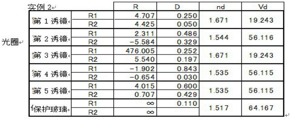
【表4】【Table 4】

如表11所示,实例2满足条件公式(1)~(13)。As shown in Table 11, Example 2 satisfies Conditional Formulas (1) to (13).
实例2中摄像镜头LA的轴向像差见图8,场曲和畸变见图8,倍率色差见图10所示。The axial aberration of the imaging lens LA in Example 2 is shown in Figure 8, the field curvature and distortion are shown in Figure 8, and the magnification chromatic aberration is shown in Figure 10.
(实例3)(Example 3)
表12示出实例2中f、Fno、2ω、BF、TL、Y的值。Table 12 shows the values of f, Fno, 2ω, BF, TL, Y in Example 2.
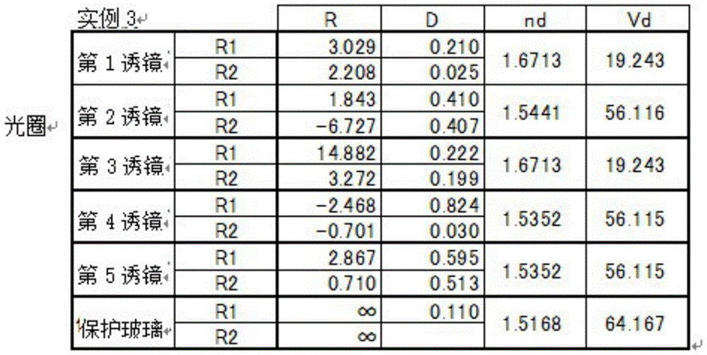
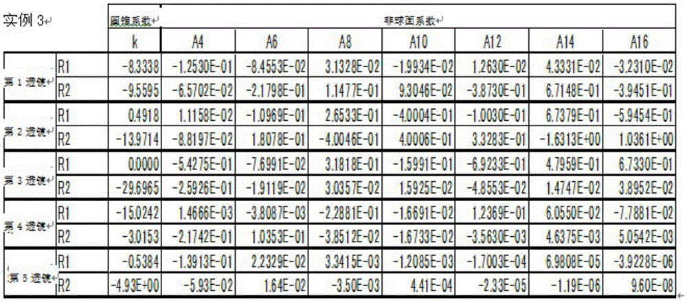
图11是实例3中摄像镜头LA的配置构成图。表5的数据有:实例3中构成摄像镜头LA的第1透镜~第5透镜的物侧的曲率半径R1、摄像侧的曲率半径R2、透镜中心厚度或透镜间的距离D、折射率nd、阿贝数vd。表6中的数据有:圆锥系数k、非球面系数。11 is a configuration configuration diagram of the imaging lens LA in Example 3. FIG. The data in Table 5 are: the curvature radius R1 of the object side of the first lens to the fifth lens constituting the imaging lens LA in Example 3, the curvature radius R2 of the imaging side, the center thickness of the lens or the distance D between the lenses, the refractive index nd, Abbe number vd. The data in Table 6 are: cone coefficient k, aspheric coefficient.
【表5】【table 5】
【表6】【Table 6】
如表11所示,实例3满足条件公式(1)~(13)。As shown in Table 11, Example 3 satisfies Conditional Formulas (1) to (13).
表12示出实例3中f、Fno、2ω、BF、TL、Y的值。Table 12 shows the values of f, Fno, 2ω, BF, TL, Y in Example 3.
实例3中摄像镜头LA的轴向像差见图12,场曲和畸变见图13,倍率色差见图14所示。The axial aberration of the imaging lens LA in Example 3 is shown in Figure 12, the field curvature and distortion are shown in Figure 13, and the chromatic aberration of magnification is shown in Figure 14.
(实例4)(Example 4)
图15是实例4中摄像镜头LA的配置构成图。表7的数据有:实例4中构成摄像镜头LA的第1透镜~第5透镜的物侧的曲率半径R1、摄像侧的曲率半径R2、透镜中心厚度或透镜间的距离D、折射率nd、阿贝数vd。表8中的数据有:圆锥系数k、非球面系数。15 is a configuration configuration diagram of the imaging lens LA in Example 4. FIG. The data in Table 7 are: the curvature radius R1 of the object side of the first to fifth lenses constituting the imaging lens LA in Example 4, the curvature radius R2 of the imaging side, the thickness of the center of the lens or the distance D between the lenses, the refractive index nd, Abbe number vd. The data in Table 8 are: cone coefficient k, aspheric coefficient.
【表7】【Table 7】

【表8】【Table 8】

如表11所示,实例4满足条件公式As shown in Table 11, Example 4 satisfies the conditional formula
(1)(2)(3)(4)(5)(6)(7)(8)(11)(12)(13)。(1)(2)(3)(4)(5)(6)(7)(8)(11)(12)(13).
表12示出实例4中f、Fno、2ω、BF、TL、Y的值。Table 12 shows the values of f, Fno, 2ω, BF, TL, Y in Example 4.
实例4中摄像镜头LA的轴向像差见图16,场曲和畸变见图17,倍率色差见图18所示。The axial aberration of the imaging lens LA in Example 4 is shown in Figure 16, the field curvature and distortion are shown in Figure 17, and the chromatic aberration of magnification is shown in Figure 18.
(实例5)(Example 5)
图19是实例5中摄像镜头LA的配置构成图。表9的数据有:实例5中构成摄像镜头LA的第1透镜~第5透镜的物侧的曲率半径R1、摄像侧的曲率半径R2、透镜中心厚度或透镜间的距离D、折射率nd、阿贝数vd。表10中的数据有:圆锥系数k、非球面系数。19 is a configuration configuration diagram of the imaging lens LA in Example 5. FIG. The data in Table 9 are: the curvature radius R1 of the object side of the first to fifth lenses constituting the imaging lens LA in Example 5, the curvature radius R2 of the imaging side, the thickness of the center of the lens or the distance D between the lenses, the refractive index nd, Abbe number vd. The data in Table 10 are: cone coefficient k, aspheric coefficient.
【表9】【Table 9】

【表10】【Table 10】

如表11所示,实例5满足条件公式As shown in Table 11, Example 5 satisfies the conditional formula
(1)(2)(3)(4)(5)(6)(7)(8)(11)(12)(13)。(1)(2)(3)(4)(5)(6)(7)(8)(11)(12)(13).
表12示出实例5中f、Fno、2ω、BF、TL、Y的值。Table 12 shows the values of f, Fno, 2ω, BF, TL, Y in Example 5.
实例5中摄像镜头LA的轴向像差见图20,场曲和畸变见图21,倍率色差见图22所示。The axial aberration of the imaging lens LA in Example 5 is shown in Figure 20, the field curvature and distortion are shown in Figure 21, and the chromatic aberration of magnification is shown in Figure 22.
【表11】【Table 11】

【表12】【Table 12】

f:摄像镜头整体的焦距f: The focal length of the camera lens as a whole
Fno:F值Fno: F value
2ω:视场角2ω: Field of View
R:光学面的曲率半径、透镜时为中心曲率半径R: The curvature radius of the optical surface, the center curvature radius in the case of a lens
R1:物侧面的曲率半径R1: Radius of curvature of the side of the object
R2:摄像侧面的曲率半径R2: Radius of curvature of the camera side
D:透镜的中心厚度或者透镜之间的距离D: The center thickness of the lens or the distance between the lenses
nd:透镜材料的d线的折射率nd: Refractive index of the d-line of the lens material
vd:透镜材料的阿贝数vd: Abbe number of the lens material
TL:光学长度(从第1透镜的物侧面到像面的轴上距离)TL: Optical length (on-axis distance from the object side of the first lens to the image plane)
BF:从第1透镜的摄像侧面到高斯像面的轴上距离BF: On-axis distance from the imaging side of the first lens to the Gaussian image plane
(玻璃平板GF的厚度除外)(Except thickness of glass plate GF)
Y:最大像高Y: Maximum image height
Claims (7)
Applications Claiming Priority (2)
| Application Number | Priority Date | Filing Date | Title |
|---|---|---|---|
| JP2017-202680 | 2017-10-19 | ||
| JP2017202680A JP6431588B1 (en) | 2017-10-19 | 2017-10-19 | Imaging lens |
Publications (2)
| Publication Number | Publication Date |
|---|---|
| CN108303781A CN108303781A (en) | 2018-07-20 |
| CN108303781B true CN108303781B (en) | 2020-10-30 |
Family
ID=62865091
Family Applications (1)
| Application Number | Title | Priority Date | Filing Date |
|---|---|---|---|
| CN201810133418.8A Expired - Fee Related CN108303781B (en) | 2017-10-19 | 2018-02-09 | Camera lens |
Country Status (3)
| Country | Link |
|---|---|
| US (1) | US10712539B2 (en) |
| JP (1) | JP6431588B1 (en) |
| CN (1) | CN108303781B (en) |
Families Citing this family (7)
| Publication number | Priority date | Publication date | Assignee | Title |
|---|---|---|---|---|
| CN110361853B (en) * | 2019-08-16 | 2021-08-20 | 诚瑞光学(常州)股份有限公司 | Camera optics |
| CN111624743B (en) * | 2020-07-22 | 2021-03-09 | 常州市瑞泰光电有限公司 | Image pickup optical lens |
| CN111781709A (en) * | 2020-08-20 | 2020-10-16 | 湖北华鑫光电有限公司 | A high-resolution 5P ultra-wide-angle lens |
| CN111929824B (en) * | 2020-09-03 | 2021-03-09 | 诚瑞光学(苏州)有限公司 | Image pickup optical lens |
| JP7656432B2 (en) * | 2021-01-28 | 2025-04-03 | 東京晨美光学電子株式会社 | Imaging lens |
| CN114355577B (en) * | 2022-01-18 | 2024-07-12 | 浙江舜宇光学有限公司 | Image pickup lens |
| CN116774396B (en) * | 2023-06-21 | 2024-05-07 | 湖北华鑫光电有限公司 | A five-piece micro mobile phone lens |
Citations (4)
| Publication number | Priority date | Publication date | Assignee | Title |
|---|---|---|---|---|
| CN104516090A (en) * | 2013-10-03 | 2015-04-15 | 光燿科技股份有限公司 | Wide-angle imaging lens group |
| CN105182503A (en) * | 2012-07-27 | 2015-12-23 | 大立光电股份有限公司 | Optical image capturing lens assembly |
| CN105629448A (en) * | 2014-11-06 | 2016-06-01 | 玉晶光电(厦门)有限公司 | Optimal imaging lens and electronic device using the same |
| CN106154508A (en) * | 2014-08-28 | 2016-11-23 | 三星电机株式会社 | Optical system |
Family Cites Families (13)
| Publication number | Priority date | Publication date | Assignee | Title |
|---|---|---|---|---|
| US7643228B2 (en) * | 2006-12-04 | 2010-01-05 | Canon Kabushiki Kaisha | Optical system and optical apparatus including optical system |
| US7710665B2 (en) * | 2007-11-08 | 2010-05-04 | Samsung Electro-Mechanics Co., Ltd. | Imaging optical system |
| JP2010008562A (en) * | 2008-06-25 | 2010-01-14 | Konica Minolta Opto Inc | Imaging lens |
| JP5423190B2 (en) * | 2009-07-09 | 2014-02-19 | 株式会社ニコン | Variable magnification optical system and optical apparatus provided with the variable magnification optical system |
| WO2012132456A1 (en) * | 2011-03-30 | 2012-10-04 | 富士フイルム株式会社 | Image pickup lens and image pickup device |
| JP2012211935A (en) * | 2011-03-30 | 2012-11-01 | Fujifilm Corp | Imaging lens and imaging apparatus |
| JP2012211934A (en) * | 2011-03-30 | 2012-11-01 | Fujifilm Corp | Imaging lens and imaging apparatus |
| TWI461731B (en) * | 2012-05-18 | 2014-11-21 | Largan Precision Co Ltd | Image lens system |
| TWI460492B (en) * | 2012-09-26 | 2014-11-11 | Sintai Optical Shenzhen Co Ltd | Slim lens assembly |
| KR101539883B1 (en) * | 2014-01-23 | 2015-07-27 | 삼성전기주식회사 | Optical system |
| KR102360175B1 (en) * | 2014-07-04 | 2022-02-08 | 삼성전자주식회사 | Photographing lens and photographing apparatus |
| KR101709834B1 (en) * | 2014-10-30 | 2017-02-23 | 삼성전기주식회사 | Lens module |
| KR101762007B1 (en) * | 2015-08-10 | 2017-07-26 | 삼성전기주식회사 | Imaging Lens System |
-
2017
- 2017-10-19 JP JP2017202680A patent/JP6431588B1/en not_active Expired - Fee Related
-
2018
- 2018-02-09 CN CN201810133418.8A patent/CN108303781B/en not_active Expired - Fee Related
- 2018-08-13 US US16/101,614 patent/US10712539B2/en active Active
Patent Citations (4)
| Publication number | Priority date | Publication date | Assignee | Title |
|---|---|---|---|---|
| CN105182503A (en) * | 2012-07-27 | 2015-12-23 | 大立光电股份有限公司 | Optical image capturing lens assembly |
| CN104516090A (en) * | 2013-10-03 | 2015-04-15 | 光燿科技股份有限公司 | Wide-angle imaging lens group |
| CN106154508A (en) * | 2014-08-28 | 2016-11-23 | 三星电机株式会社 | Optical system |
| CN105629448A (en) * | 2014-11-06 | 2016-06-01 | 玉晶光电(厦门)有限公司 | Optimal imaging lens and electronic device using the same |
Also Published As
| Publication number | Publication date |
|---|---|
| US10712539B2 (en) | 2020-07-14 |
| JP2019074716A (en) | 2019-05-16 |
| JP6431588B1 (en) | 2018-11-28 |
| US20190121091A1 (en) | 2019-04-25 |
| CN108303781A (en) | 2018-07-20 |
Similar Documents
| Publication | Publication Date | Title |
|---|---|---|
| CN111090165B (en) | Camera lens | |
| CN113238363B (en) | Camera lens | |
| CN108303781B (en) | Camera lens | |
| JP7011691B1 (en) | Imaging optical lens | |
| JP7007435B1 (en) | Imaging optical lens | |
| CN113189755B (en) | Camera lens | |
| CN111061034A (en) | camera lens | |
| JP7026764B2 (en) | Imaging optical lens | |
| JP6027202B1 (en) | Imaging lens | |
| CN107966785B (en) | camera lens | |
| CN117471655B (en) | Optical imaging system | |
| CN111352211A (en) | Small-head high-resolution lens | |
| JP2020027260A (en) | Image capturing optical lens | |
| JP2005345919A (en) | Imaging lens | |
| JP2020027265A (en) | Image capturing optical lens | |
| CN113406777B (en) | A wide-angle lens | |
| CN113433662B (en) | Imaging system, lens module, electronic equipment and carrier | |
| CN119620359B (en) | Optical lens | |
| JP2020027257A (en) | Image capturing optical lens | |
| JP2020027248A (en) | Imaging optical lens | |
| JP2020027250A (en) | Imaging optical lens | |
| CN111239983B (en) | Wide-angle photographic lens with high imaging quality | |
| JP2020027249A (en) | Imaging optical lens | |
| JP6634137B1 (en) | Imaging optical lens | |
| JP2020027256A (en) | Image capturing optical lens |
Legal Events
| Date | Code | Title | Description |
|---|---|---|---|
| PB01 | Publication | ||
| PB01 | Publication | ||
| SE01 | Entry into force of request for substantive examination | ||
| SE01 | Entry into force of request for substantive examination | ||
| TA01 | Transfer of patent application right |
Effective date of registration: 20200430 Address after: 213000 Xinwei Road, Changzhou Export Processing Zone, Jiangsu Province Applicant after: Ruisheng Communication Technology (Changzhou) Co.,Ltd. Address before: 518057 Guangdong Province, Shenzhen City Southern District of Nanshan District high tech Zone Three Road No. 6 Shenzhen Yuexing Nanjing University research building block A Applicant before: AAC ACOUSTIC TECHNOLOGIES (SHENZHEN) Co.,Ltd. |
|
| TA01 | Transfer of patent application right | ||
| GR01 | Patent grant | ||
| GR01 | Patent grant | ||
| CP03 | Change of name, title or address |
Address after: 213000 Xinwei 1st Road, Changzhou Comprehensive Bonded Zone, Jiangsu Province Patentee after: Chengrui optics (Changzhou) Co.,Ltd. Address before: 213000 Xinwei Road, Changzhou Export Processing Zone, Jiangsu Province Patentee before: Ruisheng Communication Technology (Changzhou) Co.,Ltd. |
|
| CP03 | Change of name, title or address | ||
| CF01 | Termination of patent right due to non-payment of annual fee |
Granted publication date: 20201030 |
|
| CF01 | Termination of patent right due to non-payment of annual fee |