Disclosure of Invention
The invention aims to provide an uplink multi-user joint channel estimation method, which overcomes the problems of excessive pilot frequency number and pilot frequency pollution interference required by channel estimation in the prior art.
In order to achieve the above object, the present invention provides an uplink multi-user joint channel estimation method, which includes:
step 11, realizing sparse representation of a physical channel matrix through virtual channel representation;
and step 12, modeling the channel estimation of multiple users in the target cell and the interference cell as two-dimensional sparse signal reconstruction in a compressed sensing theory, and jointly estimating the channel state information of the target multiple users by using a 2D-SL0(two-dimensional smoothed L0 algorithm) reconstruction algorithm.
Preferably, in step 11, the physical channel matrix from all K users in the ith cell to the jth cell base station is sparsely represented as
Wherein G isjiIs a physical channel matrix and Gji=[gji1,…,gjiK]Column vector gjikRepresenting the channel response vector from the kth user in the ith cell to the base station of the jth cell;
ARis a received response matrix and
where theta is
mM/M, M representing the number of base station antennas, M × K dimensional matrix
Is a sparse representation matrix and its element values
Indicating the link gain between the kth user and the mth virtual reception angle, and if the link does not exist, the element has a value of 0.
Preferably, in step 12, the method for modeling channel estimation of multiple users in a target cell and an interfering cell as two-dimensional sparse signal reconstruction includes:
the received pilot signal for the jth cell base station may be expressed as:
transposing this equation yields the following equation:
wherein H
ji=G
jiD
jiAnd H
jiRepresents the channel response matrix from the kth user in the ith cell to the jth cell site, where H
ji=[h
ji1,…,h
jiK],
β
jikThe large-scale fading factor is represented, K represents the number of single-antenna users, and K is less than M.
The following linear equation can be obtained:
Y=XGAR+N。
preferably, in step 12, the method for jointly estimating the channel state information of the target multiple users by using the 2D-SL0 reconstruction algorithm includes:
step 121, inputting an observation signal Y, an observation matrix X and a DFT transformation matrix ARThreshold value σminA contraction factor ρ, a step size μ and an iteration number Q;
Step 123, if the sigma is larger than or equal to the sigmaminSequentially executing (I) and (II); otherwise, step 124 is performed.
(I) in a feasible solution set { G | Y ═ XGA
ROn, from the initial solution
The maximization of the objective function is started by the Q-time steepest descent algorithm
(a) Setting matrix delta ═ delta
ij]Has an element value of
(b) Order to
Then pass through
Will be provided with
Projecting onto its feasible solution set;
(II) making σ ← ρ σ, and returning to step 123;
step 124, calculating and outputting
Compared with the prior art, the multi-user joint channel estimation method provided by the invention uses a two-dimensional sparse signal reconstruction algorithm 2D-SL0, can greatly reduce the number of pilot frequencies required by channel estimation, and can eliminate interference of pilot frequency pollution. The method is low in calculation complexity and easy to implement.
Additional features and advantages of the invention will be set forth in the detailed description which follows.
Detailed Description
The following detailed description of embodiments of the invention refers to the accompanying drawings. It should be understood that the detailed description and specific examples, while indicating the present invention, are given by way of illustration and explanation only, not limitation.
The invention provides an uplink multi-user joint channel estimation method, which comprises the following steps:
step 11, realizing sparse representation of a physical channel matrix through virtual channel representation;
and step 12, modeling the channel estimation of multiple users in the target cell and the interference cell into two-dimensional sparse signal reconstruction in a compressed sensing theory, and jointly estimating the channel state information of the multiple users in the target cell by using a 2D-SL0 reconstruction algorithm.
Compared with the prior art, the multi-user joint channel estimation method provided by the invention uses a two-dimensional sparse signal reconstruction algorithm 2D-SL0, can greatly reduce the number of pilot frequencies required by channel estimation, and can eliminate interference of pilot frequency pollution.
For a better understanding of the contents of the embodiments of the present invention, a system model of the embodiments of the present invention will be described in detail first. Considering a multi-cell massive MIMO system uplink scenario, each target cell shares the same band with L-1 neighboring cells, each cell has a base station with M antennas and K (K < M) single-antenna users.
The uplink channel vector from the kth user in the ith cell to the jth cell base station may be expressed as
Wherein g isjikIs a fast fading vector whose elements are independent identically distributed complex Gaussian variables with mean value of 0 and variance of 1, and large-scale fading factor βjikQuasi-static shadowing and path loss are described, so the uplink channel matrix from all K users in the ith cell to the jth cell base station can be represented as
Hji=GjiDji(formula 2)
Wherein H
ji=[h
ji1,…,h
jiK],G
ji=[g
ji1,…,g
jiK]And
in the context of a block fading channel model, the received pilot signal of the jth base station may be written as
Wherein
Which represents the signal-to-noise ratio of the uplink pilot,
the column vector in (ii) represents the pilot signals of the users in the ith cell,
representing complex additive white gaussian noise.
The embodiment of the invention discloses a method for estimating uplink multi-user joint channels of a large-scale MIMO system, which mainly comprises the following steps:
step one, virtual sparse representation of a physical channel. The virtual channel representation method describes a physical channel matrix at a series of fixed spatial domain beam angles. Considering a base station employing a uniform linear antenna array, a physical channel matrix G for massive MIMO
jiCan be mapped to a virtual channel matrix in the following way
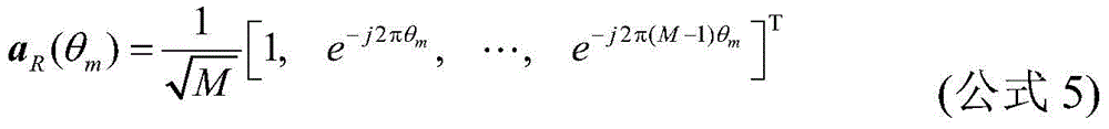
Wherein the physical channel matrix Gji=[gji1,…,gjiK],gjikRepresenting the channel response vector from the kth user in the ith cell to the base station of the jth cell, and receiving a response matrix AR=[aR(θ1),…,aR(θM)]Where the received response vector is
Wherein the direction theta
mFrom a physical angle phi
m∈[-π/2,π/2]Is in a relation of
m=dsin(φ
m) And/λ, where λ represents the wavelength and d represents the distance between the antennas. The interval of principal values for which theta is uniformly sampled is a natural choice, i.e. theta
mM/M, so that the response matrix a is received
RIs an M x M dimensional DFT transform array. M x K dimensional matrix
Refers to a sparse representation matrix whose element values
Indicating the link gain between the kth user and the mth virtual reception angle, and if the link does not exist, the element has a value of 0. If matrix
The number of non-zero elements involved is much smaller than the total number of elements in the matrix, i.e.
Where f is
iIs defined as
The number of non-zero elements in the ith column, then
Is a sparse matrix.
And step two, modeling the multi-user joint channel estimation as two-dimensional sparse signal reconstruction in a compressed sensing theory. The received pilot signal of the jth cell base station may be represented as
Transposing the formula to obtain
And thirdly, jointly estimating the channel state information of multiple users by using a 2D-SL0 two-dimensional sparse signal reconstruction algorithm. Linear equation Y ═ XGA according to (formula 7)R+ N, the specific steps of estimating the channel response by using the 2D-SL0 algorithm provided by the invention can be summarized as follows:
in order to achieve the above object, the present invention provides an uplink multi-user joint channel estimation method, which includes:
step 11, realizing sparse representation of a physical channel matrix through virtual channel representation;
and step 12, modeling the channel estimation of multiple users in the target cell and the interference cell as two-dimensional sparse signal reconstruction in a compressed sensing theory, and jointly estimating the channel state information of the target multiple users by using a 2D-SL0(two-dimensional smoothed L0 algorithm) reconstruction algorithm.
Preferably, in step 11, the physical channel matrix from all K users in the ith cell to the jth cell base station is sparsely represented as
Wherein G isjiIs a physical channel matrix and Gji=[gji1,…,gjiK]Column vector gjikRepresenting the channel response vector from the kth user in the ith cell to the base station of the jth cell;
ARis a received response matrix and
where theta is
mM/M, M representing the number of base station antennas, M × K dimensional matrix
Is a sparse representation matrix and its element values
Indicating the link gain between the kth user and the mth virtual reception angle, and if the link does not exist, the element has a value of 0.
Preferably, in step 12, the method for modeling channel estimation of multiple users in a target cell and an interfering cell as two-dimensional sparse signal reconstruction includes:
the received pilot signal for the jth cell base station may be expressed as:
transposing this equation yields the following equation:
wherein H
ji=G
jiD
jiAnd H
jiRepresents the channel response matrix from the kth user in the ith cell to the jth cell site, where H
ji=[h
ji1,…,h
jiK],
β
jikThe large-scale fading factor is represented, K represents the number of single-antenna users, and K is less than M.
The following linear equation can be obtained:
Y=XGAR+N。
preferably, in step 12, the method for jointly estimating the channel state information of the target multiple users by using the 2D-SL0 reconstruction algorithm includes:
step 121, inputting an observation signal Y, an observation matrix X and a DFT transformation matrix ARThreshold value σminA contraction factor ρ, a step size μ and an iteration number Q;
Step 123, if the sigma is larger than or equal to the sigmaminSequentially executing (I) and (II); otherwise, step 124 is performed.
(I) in a feasible solution set { G | Y ═ XGA
ROn, from the initial solution
The maximization of the objective function is started by the Q-time steepest descent algorithm
(a) Setting matrix delta ═ delta
ij]Has an element value of
(b) Order to
Then pass through
Will be provided with
Projecting onto its feasible solution set;
(II) making σ ← ρ σ, and returning to step 123;
step 124, calculating and outputting
The invention provides a multi-user joint channel estimation method of a TDD large-scale MIMO system. The provided method adopts a two-dimensional sparse signal reconstruction algorithm 2D-SL0 in the compressive sensing theory, can greatly reduce the number of required pilot frequencies, and can eliminate the influence of pilot frequency pollution. The method is low in calculation complexity and easy to implement.
To verify the effectiveness of the method of the present invention versus the advantages over prior methods, the following simulation comparative tests were performed. The scene system parameters considered are: the same frequency band is used in a single cell or 7 cells, the number of base station antennas is 256, the number of users per cell is 20, and a channel virtual representation matrix

Has random 5 elements that are non-zero. Fig. 2 is a normalized mean square error comparison diagram of applying a 2D-SL0 compressed sensing channel estimation method (labeled as the channel estimation method provided by the present invention) in a single-cell scenario and adopting different numbers of pilots in a conventional least square channel estimation method, and it can be seen from the diagram that the channel estimation method provided by the present invention can reduce the number of pilots by 40%. Fig. 3 is a normalized mean square error curve diagram of the channel estimation method provided by the present invention and the traditional least square channel estimation method using different numbers of pilots in a multi-cell scenario, and it can be seen from the diagram that the channel estimation method provided by the present invention can reduce 75% of pilot symbols, and improve the estimation accuracy by eliminating the pilot pollution.
The preferred embodiments of the present invention have been described in detail with reference to the accompanying drawings, however, the present invention is not limited to the specific details of the above embodiments, and various simple modifications can be made to the technical solution of the present invention within the technical idea of the present invention, and these simple modifications are within the protective scope of the present invention.
It should be noted that the various technical features described in the above embodiments can be combined in any suitable manner without contradiction, and the invention is not described in any way for the possible combinations in order to avoid unnecessary repetition.
In addition, any combination of the various embodiments of the present invention is also possible, and the same should be considered as the disclosure of the present invention as long as it does not depart from the spirit of the present invention.