CN105973145B - Mobile three-dimensional laser scanning system and mobile three-dimensional laser scanning method - Google Patents
Mobile three-dimensional laser scanning system and mobile three-dimensional laser scanning method Download PDFInfo
- Publication number
- CN105973145B CN105973145B CN201610334363.8A CN201610334363A CN105973145B CN 105973145 B CN105973145 B CN 105973145B CN 201610334363 A CN201610334363 A CN 201610334363A CN 105973145 B CN105973145 B CN 105973145B
- Authority
- CN
- China
- Prior art keywords
- scanning
- point cloud
- dimensional
- mobile
- movable
- Prior art date
- Legal status (The legal status is an assumption and is not a legal conclusion. Google has not performed a legal analysis and makes no representation as to the accuracy of the status listed.)
- Active
Links
- 238000000034 method Methods 0.000 title claims abstract description 46
- 238000013507 mapping Methods 0.000 claims abstract description 53
- 230000004807 localization Effects 0.000 claims abstract description 33
- 230000008569 process Effects 0.000 claims abstract description 22
- 230000007246 mechanism Effects 0.000 claims description 34
- 239000002245 particle Substances 0.000 claims description 27
- 239000011159 matrix material Substances 0.000 claims description 18
- 230000007613 environmental effect Effects 0.000 claims description 16
- 230000033001 locomotion Effects 0.000 claims description 11
- 238000012952 Resampling Methods 0.000 claims description 9
- 238000001914 filtration Methods 0.000 claims description 7
- 230000003321 amplification Effects 0.000 claims description 3
- 230000003190 augmentative effect Effects 0.000 claims description 3
- 238000003199 nucleic acid amplification method Methods 0.000 claims description 3
- 238000012545 processing Methods 0.000 claims description 3
- 238000010586 diagram Methods 0.000 description 4
- 238000005259 measurement Methods 0.000 description 3
- 230000001133 acceleration Effects 0.000 description 2
- 238000013461 design Methods 0.000 description 2
- 230000009286 beneficial effect Effects 0.000 description 1
- 238000004364 calculation method Methods 0.000 description 1
- 238000011161 development Methods 0.000 description 1
- 238000006073 displacement reaction Methods 0.000 description 1
- 238000007499 fusion processing Methods 0.000 description 1
- 238000012986 modification Methods 0.000 description 1
- 230000004048 modification Effects 0.000 description 1
- 230000009467 reduction Effects 0.000 description 1
- 230000009466 transformation Effects 0.000 description 1
- 230000001131 transforming effect Effects 0.000 description 1
- 230000007704 transition Effects 0.000 description 1
Images


Classifications
-
- G—PHYSICS
- G01—MEASURING; TESTING
- G01B—MEASURING LENGTH, THICKNESS OR SIMILAR LINEAR DIMENSIONS; MEASURING ANGLES; MEASURING AREAS; MEASURING IRREGULARITIES OF SURFACES OR CONTOURS
- G01B11/00—Measuring arrangements characterised by the use of optical techniques
Landscapes
- Physics & Mathematics (AREA)
- General Physics & Mathematics (AREA)
- Length Measuring Devices By Optical Means (AREA)
- Optical Radar Systems And Details Thereof (AREA)
- Length Measuring Devices With Unspecified Measuring Means (AREA)
Abstract
The invention relates to a mobile three-dimensional laser scanning system and a mobile three-dimensional laser scanning method. The three-dimensional point cloud scanning instrument and the sensing assembly are respectively and electrically connected with the first signal processor. The three-dimensional point cloud scanning instrument is used for carrying out three-dimensional scanning at different scanning positions and obtaining corresponding point cloud data. The first signal processor is used for updating the position and the attitude information of the scanning center of the movable scanning equipment in real time by utilizing a simultaneous localization and mapping algorithm according to the data collected by the sensing assembly, and is also used for registering the point cloud data corresponding to any scanning center to a world coordinate system according to the real-time position and the attitude information of the scanning center. The sensing assembly is used for measuring various parameters required by the simultaneous positioning and mapping algorithm. The system and the method can automatically update the position and the posture information of each scanning center when the scanning process is carried out, thereby realizing a full-automatic registration mode, improving the efficiency and being simple to operate.
Description
Technical Field
The invention relates to the technical field of three-dimensional laser scanning, in particular to a mobile three-dimensional laser scanning system and a mobile three-dimensional laser scanning method.
Background
Three-dimensional laser scanners can be divided into short-distance measuring instruments and medium-and long-distance measuring instruments according to application occasions and measuring ranges thereof. The method has wide application range, such as scenes in game development, indoor design, measurement of whole vehicle part design, accident site reduction, national cultural heritage protection, archaeological work and the like.
The data measured by the three-dimensional laser scanner when scanning scene data once all uses one scanning center as a reference point. Wherein the scan center generally refers to the origin of the three-dimensional laser scanner coordinate system. If the scanning needs to be performed for multiple times in a large scene, and data fusion processing is performed on the data obtained through multiple times of scanning, then the relative position relationship among multiple scanning centers needs to be obtained, including the position information and the attitude information, that is, the position information and the attitude information of the multiple scanning centers need to be registered in a certain registration mode in the space.
However, in the conventional registration method, the relative position relationship of each scan center is manually input (or manually dragged) in the active registration, which is complicated and inefficient. The semi-automatic target registration is to calculate the relative position relationship of each scanning center by scanning the same calibration device (calibration ball or other calibration devices) for multiple times, and the operation is complex, the requirement on the placement of the calibration device is high, and the efficiency is not high.
Disclosure of Invention
Accordingly, it is necessary to provide a mobile three-dimensional laser scanning system and a mobile three-dimensional laser scanning method for solving the problem of low efficiency of the conventional registration method.
A mobile three-dimensional laser scanning system comprises a mobile scanning device which can move and at least comprises a sensing assembly and a three-dimensional point cloud scanning instrument, and further comprises a first signal processor; the three-dimensional point cloud scanning instrument and the sensing assembly are respectively and electrically connected with the first signal processor;
the three-dimensional point cloud scanning instrument is used for carrying out three-dimensional scanning at different scanning positions and obtaining corresponding point cloud data;
the first signal processor is used for updating the position and posture information of the scanning center of the movable scanning equipment in real time according to the data collected by the sensing assembly and by utilizing a simultaneous localization and mapping algorithm, registering the point cloud data corresponding to any scanning center into a world coordinate system according to the real-time position and posture information of the scanning center, and performing three-dimensional modeling according to the registered point cloud data;
the sensing assembly is used for measuring various parameters required by the simultaneous localization and mapping algorithm.
In one embodiment, the first signal processor updates the position and attitude information of the scan center of the movable scanning device using an unscented kalman filter-based simultaneous localization and mapping algorithm.
In one embodiment, the first signal processor comprises a simultaneous localization and mapping unit, a three-dimensional point cloud registration unit and a three-dimensional modeling unit which are connected in sequence; the simultaneous positioning and drawing unit is also connected with the sensing assembly; the three-dimensional point cloud registration unit is also connected with the three-dimensional point cloud scanning instrument;
the simultaneous positioning and mapping unit is used for updating the position and posture information of the scanning center of the movable scanning equipment in real time according to the data acquired by the sensing assembly and by utilizing a simultaneous positioning and mapping algorithm;
the three-dimensional point cloud registration unit is used for registering point cloud data corresponding to any scanning center into a world coordinate system according to the real-time position and posture information of the scanning center and sending the registered data to the three-dimensional modeling unit;
and the three-dimensional modeling unit is used for carrying out three-dimensional modeling according to the point cloud data after registration.
In one embodiment, the mobile scanning device further comprises a GPS module; the GPS module is connected with the first signal processor and is used for measuring the initial scanning position of the movable scanning equipment.
In one embodiment, the sensing components include an attitude sensor, a speed sensor, and a distance sensor.
In one embodiment, the movable scanning apparatus further comprises a moving mechanism and a supporting mechanism; the moving mechanism is arranged at the bottom of the supporting mechanism and is used for driving the supporting mechanism to move to each scanning position;
the three-dimensional point cloud scanning instrument is arranged on the supporting mechanism; the sensing assembly is arranged on the moving mechanism or the supporting mechanism;
in one embodiment, the three-dimensional point cloud scanning instrument is placed on top of the movable scanning device.
A mobile three-dimensional laser scanning method based on the mobile three-dimensional laser scanning system, wherein the execution of the first signal processor comprises:
setting initial position and attitude information of a scanning center of the movable scanning equipment;
receiving initial point cloud data scanned by the three-dimensional point cloud scanning instrument at an initial scanning position;
registering the initial point cloud data into a world coordinate system according to the initial position and posture information;
receiving data collected by the sensing assembly in real time and updating the position and posture information by utilizing a simultaneous positioning and mapping algorithm in the process that the movable scanning equipment moves to the next scanning position;
receiving another set of point cloud data scanned by the three-dimensional point cloud scanning instrument at the next scanning position;
registering the other group of point cloud data into a world coordinate system according to the position and posture information corresponding to the next scanning position;
judging whether the movable scanning equipment finishes scanning or not, and if so, performing three-dimensional modeling according to the registered point cloud data corresponding to each scanning position; otherwise, continuously executing the step of receiving the data collected by the sensing assembly in real time and updating the position and posture information by utilizing a simultaneous positioning and mapping algorithm in the process that the movable scanning equipment moves to the next scanning position.
A mobile three-dimensional laser scanning system is connected with a three-dimensional modeling processor, the three-dimensional modeling processor is used for carrying out three-dimensional modeling according to data sent by the mobile three-dimensional laser scanning system, the mobile three-dimensional laser scanning system comprises mobile scanning equipment which can move, the mobile scanning equipment at least comprises a three-dimensional point cloud scanning instrument and a sensing assembly, and the mobile three-dimensional laser scanning system further comprises a second signal processor; the three-dimensional point cloud scanning instrument and the sensing assembly are respectively and electrically connected with the second signal processor;
the three-dimensional point cloud scanning instrument is used for carrying out three-dimensional scanning at different scanning positions and obtaining corresponding point cloud data;
the second signal processor is used for updating the position and posture information of the scanning center of the movable scanning equipment in real time by utilizing a simultaneous localization and mapping algorithm according to the data collected by the sensing assembly, registering the point cloud data corresponding to any scanning center into a world coordinate system according to the real-time position and posture information of the scanning center, and sending the registered data to the three-dimensional modeling processor;
the sensing assembly is used for measuring various parameters required by the simultaneous localization and mapping algorithm.
A mobile three-dimensional laser scanning method based on the mobile three-dimensional laser scanning system, wherein the second signal processor performs the steps of:
setting initial position and attitude information of a scanning center of the movable scanning equipment;
receiving initial point cloud data scanned at an initial scanning position by the three-dimensional point cloud data scanner;
registering the initial point cloud data into a world coordinate system according to the initial position and posture information, and sending the registered point cloud data to the three-dimensional modeling processor;
receiving data collected by the sensing assembly in real time and updating the position and posture information by utilizing a simultaneous positioning and mapping algorithm in the process that the movable scanning equipment moves to the next scanning position;
receiving another set of point cloud data scanned by the three-dimensional point cloud data scanner at the next scanning position;
registering the other group of point cloud data into a world coordinate system according to the position and posture information corresponding to the next scanning position, and sending the registered point cloud data to the three-dimensional modeling processor;
and when the movable scanning equipment is judged not to be scanned completely, continuously executing the steps of receiving the data collected by the sensing assembly in real time and updating the position and posture information by utilizing a simultaneous positioning and drawing algorithm in the process that the movable scanning equipment moves to the next scanning position.
The mobile three-dimensional laser scanning system and the mobile three-dimensional laser scanning method have the beneficial effects that: and the three-dimensional point cloud scanning instrument is used for carrying out three-dimensional scanning at different scanning positions and obtaining corresponding point cloud data. The first signal processor is used for updating the position and the attitude information of the scanning center of the movable scanning equipment in real time by utilizing a simultaneous localization and mapping algorithm according to the data collected by the sensing assembly, and is also used for registering the point cloud data corresponding to any scanning center to a world coordinate system according to the real-time position and attitude information of the scanning center. Therefore, the mobile three-dimensional laser scanning system and the mobile three-dimensional laser scanning method can automatically update the position and posture information of each scanning center while the scanning process is carried out, thereby realizing a full-automatic registration mode, improving the efficiency and being simple to operate.
Drawings
In order to more clearly illustrate the embodiments of the present invention or the technical solutions in the prior art, the drawings used in the description of the embodiments or the prior art will be briefly described below, it is obvious that the drawings in the following description are only some embodiments of the present invention, and for those skilled in the art, other drawings of the embodiments can be obtained according to the drawings without creative efforts.
Fig. 1 is a schematic structural diagram of a mobile three-dimensional laser scanning system according to an embodiment;
FIG. 2 is a schematic diagram of another exemplary embodiment of the mobile three-dimensional laser scanning system shown in FIG. 1;
FIG. 3 is a schematic diagram of an external structure of the mobile three-dimensional laser scanning system of FIG. 2;
FIG. 4 is a flowchart of a mobile three-dimensional laser scanning method performed by the first signal processor in the embodiment shown in FIG. 1;
fig. 5 is a schematic structural diagram of a mobile three-dimensional laser scanning system according to another embodiment;
fig. 6 is a flowchart of a mobile three-dimensional laser scanning method performed by the second signal processor in the embodiment shown in fig. 5.
Detailed Description
To facilitate an understanding of the invention, the invention will now be described more fully with reference to the accompanying drawings. Preferred embodiments of the present invention are shown in the drawings. This invention may, however, be embodied in many different forms and should not be construed as limited to the embodiments set forth herein. Rather, these embodiments are provided so that this disclosure will be thorough and complete.
Unless defined otherwise, all technical and scientific terms used herein have the same meaning as commonly understood by one of ordinary skill in the art to which this invention belongs. The terminology used in the description of the invention herein is for the purpose of describing particular embodiments only and is not intended to be limiting of the invention. As used herein, the term "and/or" includes any and all combinations of one or more of the associated listed items.
One embodiment provides a mobile three-dimensional laser scanning system. As shown in fig. 1, the mobile three-dimensional laser scanning system includes a mobile scanning apparatus 100 and a first signal processor 200. The movable scanning apparatus 100 is capable of moving, and the movable scanning apparatus 100 at least includes a sensing component 110 and a three-dimensional point cloud scanning instrument 120. In other embodiments, the first signal processor 200 may also be provided in the movable scanning apparatus 100 so as to follow the movement of the movable scanning apparatus 100. Meanwhile, the three-dimensional point cloud scanning instrument 120 and the sensing assembly 110 are electrically connected to the first signal processor 200, respectively.
And the three-dimensional point cloud scanning instrument 120 is used for performing three-dimensional scanning at different scanning positions and obtaining corresponding point cloud data. Since the movable scanning apparatus 100 is movable, it can be moved to different scanning positions, each corresponding to one scanning center. The scanning positions of the movable scanning device 100 are different, the corresponding scanning centers are different, and the point cloud data obtained by scanning are correspondingly different. Specifically, the three-dimensional point cloud scanning instrument 120 may be a three-dimensional laser scanner or other instrument capable of three-dimensional scanning. Meanwhile, the point cloud data that can be scanned by the three-dimensional point cloud scanning instrument 120 may be 360 degrees × 180 degrees all-around point cloud data, so as to obtain accurate scene data.
And the first signal processor 200 is used for updating the position and posture information of the scanning center of the movable scanning device 100 in real time according to the data collected by the sensing assembly 110 and by utilizing a simultaneous positioning and mapping algorithm. Specifically, the sensing assembly 110 collects data in real time as the movable scanning device 100 moves from the previous scanning position to the next scanning position. Meanwhile, the first signal processor 200 updates the position and posture information of the scanning center of the movable scanning device 100 in real time according to the data collected by the sensing component 110, so as to ensure that the corresponding position and posture information of the scanning center can be obtained when the movable scanning device 100 moves to the next scanning position, and therefore, the first signal processor 200 can fully automatically register the position and posture information of a plurality of scanning centers. The principle of the simultaneous positioning and mapping algorithm is as follows: in an unfamiliar environment, a moving object detects the surrounding environment by using a sensor loaded by the moving object and generates an environment map, and meanwhile, the position of the moving object in the environment map is determined.
Meanwhile, the first signal processor 200 is further configured to register point cloud data corresponding to any scanning center into a world coordinate system according to the real-time position and posture information of the scanning center, and perform three-dimensional modeling according to the registered point cloud data. The point cloud data, the position and the posture information adopted by the first signal processor 200 in the registration each time correspond to a corresponding scanning center. After scanning is finished, point cloud data in the world coordinate system corresponding to each scanning center can be obtained, and therefore three-dimensional modeling can be conducted according to the point cloud data. The three-dimensional modeling is a point cloud-based three-dimensional modeling technology, and can be a point cloud curved surface reconstruction technology, a point cloud triangular meshing technology and the like.
The sensing component 110 is used for measuring various parameters required by the above-mentioned simultaneous localization and mapping algorithm. The parameters required by the simultaneous positioning and mapping algorithm comprise parameters related to the control quantity and the observed quantity. The control quantity is control information in the motion model for controlling the relationship between the previous time and the current time pose of the movable scanning apparatus 100. Specifically, the control amount may include a velocity or an angular velocity. The observed quantity is a relative pose relationship between the environmental feature point and the current movable scanning apparatus 100.
In summary, the mobile three-dimensional laser scanning system can automatically update the position and posture information of each scanning center while the scanning process is performed, so as to realize a full-automatic registration mode, improve the efficiency, and be simple to operate.
Specifically, the first signal processor 200 updates the position and orientation information of the scan center of the movable scanning device 100 using a unscented kalman filter (i.e., the UKF algorithm) based simultaneous localization and mapping algorithm. The ufastsum algorithm is based on a frame of Fast SLAM (Simultaneous Localization And Mapping) algorithm, And replaces EKF (Extended Kalman Filter) filtering with unscented Kalman filtering, so that the accuracy of the algorithm is improved compared with the fastslm based on EKF filtering, thereby improving the accuracy of the first signal processor 200 in calculating the position And attitude information of the scanning center of the movable scanning device 100. The basic principle of the ufastsum algorithm will be described below.
First, the principle of Unscented kalman filter algorithm is introduced, and the implementation flow is as follows.
1
2
3
4
5
6
7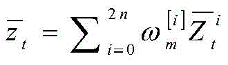
8
9
10
11
12
In the first step, the UKF algorithm is based on the mean value x of the state variables of the previous momentt-1Sum variance Pt-1Extracting 2n +1 Sigma points (line 1), passing the Sigma points through a nonlinear motion equation (line 2), and predicting the mean value of the state variable at the current moment according to the weight values of the Sigma points Sum variance
 (line 3, 4). The second step, the predicted value obtained according to the previous step
 And (4) extracting 2n +1 Sigma points again (line 5), solving the Sigma point transformation of the nonlinear observation equation (line 6), and finally solving the variance and the mean of the observation quantity predicted values (lines 7 and 8). And thirdly, calculating the cross covariance and the Kalman gain according to the obtained result (lines 9 and 10). The fourth step is based onThe kalman gain and the difference between the true and predicted observations perform a location update on the mean and variance of the system state variables (lines 11, 12).
Next, the operation principle of the first signal processor 200 updating the position and orientation information of the scan center in real time by using the ufastsum algorithm in this embodiment will be specifically described. In addition, the following operation principle assumes that the control amount and the posture of the movable scanning apparatus 100 are kept constant in the time interval of (t-1, t) in an ideal state.
1. Position estimation and updating for a mobile scanning device 100
First, the position of the movable scanning apparatus 100 at the previous time (i.e., time t-1), the control amount and its noise, and the observed amount and its noise are collectively added to the matrix of the position and variance of the movable scanning apparatus 100 as shown in the following equation:


wherein the amplification matrix A matrix with dimensions 9 x 1 containing the position of the
 movable scanning apparatus 100 at time t-1, the control quantity, and the observation quantity information. The control quantity and the observed quantity are obtained according to the relevant data collected by the sensing assembly 110 at the time t-1. Augmented matrix A matrix with dimensions 9 x 9 containing the position variance of the
 movable scanning device 100, the control noise and the observation noise information. RtRepresenting control noise. QtRepresenting the observed noise.
Then 2n +1(n is the dimension of the mean vector, where n is 9) Sigma points are extracted around the mean point according to equation (1), so the set of extracted Sigma points is shown below.



Further, the Sigma points obtained by transforming the Sigma points by the nonlinear motion model can be obtained as follows.

Wherein u istIs the control quantity measured by the sensing component 110 at time t. At this point, the predicted values of the mean and variance of the position of the mobile scanning device 100 at time t can be calculated from the weights of the Sigma points, as follows.


Wherein, is the weight of the mean value of the Sigma points,
 is the mean weight of the Sigma points. Then, the predicted value in the above equation is updated by using the observed information, i.e., the actual observed quantity observed by the
 sensor unit 110 at time t, as shown below.


Wherein Is the Sigma point through the non-linear observation equation,
 is a predicted value of the observation that,
 is an updated vector. The cross covariance matrix and kalman gain can thus be found, as shown below.


Further, the Kalman gain and the real observed value z can be obtainedtPredicted value from observation The difference between updates the mean and variance of the position of the
 mobile scanning device 100 as follows.


The Sigma point set of equation (2) is updated from the above equation, as shown below.

2. Estimation and updating of environmental landmark positions
First, a Sigma point set of three-dimensional environmental features is constructed from the mean of the observed quantities, as shown in the following equation.


Wherein Is the average of the nth environmental feature at time t-1,
 is the variance of the nth environmental feature at time t-1, and the rest of the parameters are as described above. The Sigma point sets are subjected to a nonlinear observation equation to obtain
 As follows.

Further, the predicted values of the mean and variance of the observed values can be obtained as follows.


The cross-covariance, kalman gain, may then be calculated, and the mean and variance of the environmental feature locations updated, as shown below.


3. Calculating particle weight for resampling process
First, we need to calculate the weight of each particle, and the calculation formula is shown below.

Wherein In order to reduce the particle depletion phenomenon, whether the number of effective particles is lower than a threshold value needs to be judged, if so, the algorithm needs to perform resampling, so that resampling in each iteration process can be avoided.
The principle of resampling is as follows: the prior probability at time t-1 can be approximated by a weighted particle. After the system observes and recalculates the weight, the particles with large weight can be classified into a plurality of new particles, and the particles with small weight are discarded, so that a group of new particles can be obtained. The state at the moment t, namely the system state transition process, can be predicted by adding random quantity to the new particles. And finally, entering the system observation process again, and predicting the state at the next moment.
Then, based on the above-mentioned principles of estimating and updating the position of the movable scanning device 100, estimating and updating the positions of the environmental feature points, calculating the particle weights, and performing resampling processing, the first signal processor 200 may update the position and orientation information of the movable scanning device 100 in real time according to the iteration and loop process corresponding to the ufastsum algorithm.
Specifically, as shown in fig. 2, the first signal processor 200 includes a simultaneous localization and mapping unit 210, a three-dimensional point cloud registration unit 220, and a three-dimensional modeling unit 230, which are connected in sequence. Wherein the simultaneous localization and mapping unit is further connected to the sensing assembly 110. The three-dimensional point cloud registration unit 220 is also connected to the three-dimensional point cloud scanning instrument 120.
Wherein, the simultaneous localization and mapping unit 210 receives data collected by the sensing assembly 110 in real time. In addition, the simultaneous localization and mapping unit 210 is configured to update the position and orientation information of the scan center of the movable scanning apparatus 100 in real time according to the data collected by the sensing assembly 110 and using a simultaneous localization and mapping algorithm. In this embodiment, the simultaneous localization and mapping unit 210 updates the position and orientation information of the scan center of the movable scanning device 100 in real time by using the unscented kalman filter-based simultaneous localization and mapping algorithm.
The three-dimensional point cloud registration unit 220 is configured to receive point cloud data scanned at each scanning position by the three-dimensional point cloud scanning instrument 120. Meanwhile, the three-dimensional point cloud registration unit 220 is configured to register point cloud data corresponding to any scanning center into a world coordinate system according to real-time position and posture information of the scanning center, and send the registered data to the three-dimensional modeling unit 230. The point cloud data, position and attitude information used by the three-dimensional point cloud registration unit 220 in registration corresponds to a corresponding one of the scan centers.
And a three-dimensional modeling unit 230, configured to perform three-dimensional modeling according to the registered point cloud data sent by the three-dimensional point cloud registration unit 220. After the movable scanning device 100 moves to all scanning positions and scans, the three-dimensional modeling unit 230 may perform three-dimensional modeling according to the registered point cloud data obtained from all scanning centers.
Wherein, the positioning and mapping unit 210 updates the position and posture information of the movable scanning apparatus 100 in real time while the movable scanning apparatus 100 moves from the previous scanning position to the next scanning position. When the movable scanning apparatus 100 moves to the next scanning position, the simultaneous localization and mapping unit 210 sends the position and orientation information corresponding to the scanning center of the next scanning position to the three-dimensional point cloud registration unit 220. Meanwhile, the three-dimensional point cloud scanning instrument 120 starts scanning and sends the point cloud data obtained by scanning to the three-dimensional point cloud registration unit 220. The three-dimensional point cloud registration unit 220 may then register the point cloud data according to the position and posture information, and send the registered point cloud data to the three-dimensional modeling unit 230.
It should be noted that the simultaneous localization and mapping unit 210, the three-dimensional point cloud registration unit 220, and the three-dimensional modeling unit 230 may be disposed on the movable scanning apparatus 100, or may be disposed outside the movable scanning apparatus 100.
It is to be understood that the specific structure of the first signal processor 200 is not limited to the above-described one as long as the position and posture information of the scan center of the movable scanning apparatus 100 can be updated in real time and the point cloud data can be registered into the world coordinate system for three-dimensional modeling.
In particular, as shown in FIG. 2, the mobile scanning device 100 also includes a GPS module 130. And a GPS module 130 connected to the first signal processor 200 and measuring an initial scanning position of the movable scanning apparatus 100. When the mobile scanning device 100 is at the initial scanning position, the GPS module 130 can collect longitude and latitude data of the mobile scanning device 100, so that the first signal processor 200 can set initial position information of the scanning centers, and then, in the subsequent moving process, the position information of each scanning center is updated by calculating the relative displacement between each scanning center based on the initial position information.
Meanwhile, the sensing assembly 110 includes an attitude sensor 111, a speed sensor 112, and a distance sensor 113. The attitude sensor 111 is used for measuring the attitude of the movable scanning apparatus 100, and can be used in the motion model and the observation model of the above-mentioned simultaneous localization and mapping algorithm. Attitude sensor 111 may be an electronic compass or other type of attitude sensor.
The velocity sensor 112 is used to measure the velocity, angular velocity or angular acceleration of the movable scanning apparatus 100, and may provide information about the position and control quantities in the mapping algorithm. The speed sensor 112 may include an encoder, an inertial measurement unit, or other type of sensor. Wherein the encoder is capable of measuring the speed of the movable scanning device 100. The inertial measurement unit is capable of measuring the three-axis angular velocity and the three-cycle angular acceleration of the movable scanning apparatus 100.
The distance sensor 113, placed horizontally, measures the relative positional relationship between the environmental features and the movable scanning apparatus 100 over a 360 degree range, and provides information about simultaneous localization and observation in a mapping algorithm. The distance sensor 113 may be a two-dimensional lidar, a camera based on TOF (Time of Flight) technology, or a three-dimensional lidar.
It is understood that the specific sensor type of the sensing assembly 110 is not limited to the above-mentioned one, as long as the requirement of the first signal processor 200 to update the position and attitude information of the scanning center of the movable scanning apparatus 100 in real time can be satisfied.
Specifically, as shown in fig. 3, the movable scanning apparatus 100 further includes a moving mechanism 140 and a supporting mechanism 150. The moving mechanism 140 is installed at the bottom of the supporting mechanism 150 and is used for driving the supporting mechanism 150 to move to each scanning position. The moving state of the moving mechanism 140 can be manually operated by a user, and the moving mechanism 140 can be controlled by the corresponding control mechanism to move. Specifically, the moving mechanism 140 may be a roller. And a supporting mechanism 150 for carrying the three-dimensional point cloud scanning instrument 120 and the related sensors in the sensing assembly 110.
In this embodiment, the three-dimensional point cloud scanning instrument 120 is mounted to the support mechanism 150. Specifically, the three-dimensional point cloud scanning instrument 120 is disposed on the top of the movable scanning device 100, that is, the three-dimensional point cloud scanning instrument 120 is disposed on the top of the supporting mechanism 150, so that there is no obstruction around the three-dimensional point cloud scanning instrument 120, and thus, all-directional point cloud data can be obtained.
The sensing assembly 110 is mounted to the moving mechanism 140 or the supporting mechanism 150. Wherein the encoder in the speed sensor 112 is mounted on the moving mechanism 140 to facilitate the determination of the speed of the movable scanning apparatus 100 based on the rotational speed of the wheel. Other sensors may be mounted to both the movement mechanism 140 and the support mechanism 150.
Therefore, in this embodiment, the movable scanning device 100 can be moved to each scanning position by controlling the moving mechanism 140, and the registered point cloud data corresponding to each scanning position can be finally obtained through the sensing component 110 and the first signal processor 200, so as to perform three-dimensional modeling, and the method is simple in operation, convenient to carry, fast and efficient.
It is to be understood that the specific structure of the movable scanning apparatus 100 is not limited to the above-described one as long as the movable three-dimensional laser scanning system can be normally operated.
Based on the mobile three-dimensional laser scanning system, the embodiment further provides a mobile three-dimensional laser scanning method. The steps executed by the first signal processor 200 include the following steps, as shown in fig. 4.
Step S110, initial position and attitude information of the scanning center of the movable scanning apparatus 100 is set.
The first signal processor 200 may acquire initial longitude and latitude data of the initial scanning position P0 through the GPS module 130, thereby setting initial position information of the scanning center as (Xp0, Yp0, Zp 0). The first signal processor 200 may acquire initial attitude information of the scan center through the attitude sensor 111, denoted as (Ap0, Bp0, Cp 0). Meanwhile, the three-dimensional point cloud scanning instrument 120 scans at the initial scanning position and sends the initial point cloud data obtained after scanning to the first signal processor 200.
Step S120, receiving initial point cloud data scanned by the three-dimensional point cloud scanning instrument 120 at the initial scanning position P0, and recording as M0.
And S130, registering the initial point cloud data into a world coordinate system according to the initial position and posture information.
The first signal processor 200 registers the initial point cloud data M0 to the world coordinate system according to the initial position information (Xp0, Yp0, Zp0) and the initial attitude information (Ap0, Bp0, Cp0), and the registered data is recorded as M0'.
Step S140, receiving data collected by the sensing assembly 110 in real time during the movement of the movable scanning device 100 to the next scanning position P1, and updating the position and attitude information of the scanning center using the simultaneous localization and mapping algorithm.
When the mobile scanning device 100 moves to the next scanning position P1, the first signal processor 200 can calculate the position information (Xp1, Yp1, Zp1) and attitude information (Ap1, Bp1, Cp1) of the scanning center at the scanning position P1 in time. Meanwhile, the three-dimensional point cloud scanning instrument 120 scans at the scanning position P1 to obtain another set of point cloud data M1, and sends the data to the first signal processor 200.
Step S150, another set of point cloud data M1 scanned by the three-dimensional point cloud scanning apparatus 120 at the next scanning position P1 is received.
And S160, registering another group of point cloud data M1 into a world coordinate system according to the position and posture information corresponding to the next scanning position P1.
Wherein the first signal processor 200 registers another set of point cloud data M1 to the world coordinate system according to the above position information (Xp1, Yp1, Zp1) and attitude information (Ap1, Bp1, Cp1), and the registered data is denoted as M1'.
Step S170, determining whether the mobile scanning device 100 finishes scanning, if yes, executing step S180; otherwise, the step S140 is executed continuously.
Wherein, the movable scanning device 100 scans all the scanning positions. Then, in the subsequent scanning positions P2, …, Pn, the corresponding updated position information is (Xp2, Yp2, Zp2), … (Xpn, Ypn, Zpn), the attitude information is (Ap2, Bp2, Cp2), … (Apn, Bpn, Cpn), the point cloud data obtained by the three-dimensional point cloud scanning apparatus 120 is M2, … Mn, respectively, and the point cloud data after registration is M2', … Mn'.
And S180, performing three-dimensional modeling according to the registered point cloud data corresponding to each scanning position.
The first signal processor 200 finally performs three-dimensional modeling according to the sets of registered point cloud data M1, M2, … Mn, thereby completing the reconstruction process of the scene data.
In summary, the mobile three-dimensional laser scanning method can automatically update the position and posture information of each scanning center while the scanning process is performed, thereby realizing a fully automatic registration mode, improving the efficiency and being simple to operate.
FIG. 4 is a flow chart illustrating a method according to an embodiment of the present invention. It should be understood that, although the steps in the flowchart of fig. 4 are shown in order as indicated by the arrows, the steps are not necessarily performed in order as indicated by the arrows. The steps are not performed in the exact order shown and may be performed in other orders unless explicitly stated herein. Moreover, at least a portion of the steps in fig. 4 may include multiple sub-steps or multiple stages that are not necessarily performed at the same time, but may be performed at different times, in different orders, and may be performed alternately or at least partially with respect to other steps or sub-steps of other steps.
In another embodiment, as shown in fig. 5, a mobile three-dimensional laser scanning system 300 is also provided. The mobile three-dimensional laser scanning system 300 is connected to a three-dimensional modeling processor 400. Meanwhile, the three-dimensional modeling processor 400 is configured to perform three-dimensional modeling based on data transmitted from the mobile three-dimensional laser scanning system 300.
The mobile three-dimensional laser scanning system 300 includes a mobile scanning device 310, and the mobile scanning device 310 includes at least a three-dimensional point cloud scanning apparatus 312 and a sensing component 311. The mobile three-dimensional laser scanning system 300 also includes a second signal processor 320. The three-dimensional point cloud scanning instrument 312 and the sensing component 311 are respectively electrically connected 320 with the second signal processor.
And a three-dimensional point cloud scanning instrument 312 for performing three-dimensional scanning at different scanning positions and obtaining corresponding point cloud data.
The second signal processor 320 is configured to update the position and posture information of the scanning center of the movable scanning device 310 in real time according to the data collected by the sensing component 311 and by using a simultaneous localization and mapping algorithm, and the second signal processor 320 is further configured to register point cloud data corresponding to any scanning center into a world coordinate system according to the real-time position and posture information of the scanning center, and send the registered data to the three-dimensional modeling processor 400.
And the sensing component 311 is used for measuring various parameters required by the simultaneous localization and mapping algorithm.
It should be noted that, in this embodiment, the mobile three-dimensional laser scanning system 300 does not have the function of three-dimensional modeling, specifically, the second signal processor 320 does not include the function of the three-dimensional modeling unit 230, and the specific implementation principle of the other structures is the same as that of the above embodiment, and will not be described again here.
Based on the mobile three-dimensional laser scanning system in another embodiment, a mobile three-dimensional laser scanning method is also provided. The steps executed by the second signal processor 320 are shown in fig. 6.
Step S210 sets initial position and attitude information of the scanning center of the movable scanning device 310.
The second signal processor 320 may acquire initial longitude and latitude data of the initial position P0 through the GPS module, thereby setting initial position information of the scan center to (Xp0, Yp0, Zp 0). The second signal processor 320 may obtain initial attitude information of the scan center through an attitude sensor, which is set to (Ap0, Bp0, Cp 0). Meanwhile, the three-dimensional point cloud scanning instrument 312 starts scanning at the initial position, and sends the initial point cloud data obtained after scanning to the second signal processor 320.
Step S220, receiving the initial point cloud data scanned by the three-dimensional point cloud scanning apparatus 312 at the initial position P0, and setting the data as M0.
Step S230, registering the initial point cloud data to a world coordinate system according to the initial position and posture information, and sending the registered point cloud data to the three-dimensional modeling processor 400.
The second signal processor 320 registers the initial point cloud data M0 to the world coordinate system according to the initial position information (Xp0, Yp0, Zp0) and the initial attitude information (Ap0, Bp0, Cp0), and the registered data is marked as M0'.
Step S240, during the process of moving the movable scanning device 310 to the next scanning position P1, receiving the data collected by the sensing component 311 in real time, and updating the position and posture information of the scanning center by using the simultaneous localization and mapping algorithm.
Then when the movable scanning device 310 moves to the next scanning position P1, the second signal processor 320 can calculate the position information (Xp1, Yp1, Zp1) and attitude information (Ap1, Bp1, Cp1) of the position in time. Meanwhile, the three-dimensional point cloud scanning instrument 312 starts scanning another set of point cloud data M1 at the next scanning position P1 and sends it to the second signal processor 320.
Step S250, another set of point cloud data M1 scanned by the three-dimensional point cloud scanning instrument 312 at the next scanning position P1 is received.
And S260, registering another group of point cloud data M1 to a world coordinate system according to the position and posture information corresponding to the next scanning position P1, and sending the registered point cloud data to the three-dimensional modeling processor 400.
Wherein the second signal processor 320 registers another set of point cloud data M1 to the world coordinate system according to the above position information (Xp1, Yp1, Zp1) and attitude information (Ap1, Bp1, Cp1), and the registered data is denoted as M1'.
Step S270, determining whether the movable scanning device 310 finishes scanning, and if so, finishing the execution; otherwise, the step S240 is continuously executed.
In the subsequent scanning positions P2, …, Pn, the corresponding updated position information is (Xp2, Yp2, Zp2), … (Xpn, Ypn, Zpn), the attitude information is (Ap2, Bp2, Cp2), … (Apn, Bpn, Cpn), the point cloud data obtained by the three-dimensional point cloud scanning apparatus 312 are M2, … Mn, respectively, and the point cloud data after registration are M2', … Mn'.
The movable scanning device 310 scans all the scanning positions. The final three-dimensional modeling processor 400 performs three-dimensional modeling according to all the registered point cloud data sent by the mobile three-dimensional laser scanning system 300, thereby completing the reconstruction process of the scene data.
In summary, the mobile three-dimensional laser scanning method can automatically update the position and posture information of each scanning center while the scanning process is performed, thereby realizing a fully automatic registration mode, improving the efficiency and being simple to operate.
It should be noted that fig. 6 is a schematic flow chart of a method according to another embodiment of the present invention. It should be understood that, although the steps in the flowchart of fig. 6 are shown in order as indicated by the arrows, the steps are not necessarily performed in order as indicated by the arrows. The steps are not performed in the exact order shown and may be performed in other orders unless explicitly stated herein. Moreover, at least a portion of the steps in fig. 6 may include multiple sub-steps or multiple stages that are not necessarily performed at the same time, but may be performed at different times, in different orders, and may be performed alternately or at least partially with respect to other steps or sub-steps of other steps.
The technical features of the embodiments described above may be arbitrarily combined, and for the sake of brevity, all possible combinations of the technical features in the embodiments described above are not described, but should be considered as being within the scope of the present specification as long as there is no contradiction between the combinations of the technical features.
The above-mentioned embodiments only express several embodiments of the present invention, and the description thereof is more specific and detailed, but not construed as limiting the scope of the invention. It should be noted that, for a person skilled in the art, several variations and modifications can be made without departing from the inventive concept, which falls within the scope of the present invention. Therefore, the protection scope of the present patent shall be subject to the appended claims.
Claims (9)
1. A mobile three-dimensional laser scanning system is characterized by comprising a mobile scanning device which can move, wherein the mobile scanning device at least comprises a sensing component and a three-dimensional point cloud scanning instrument, and the mobile three-dimensional laser scanning system also comprises a first signal processor; the three-dimensional point cloud scanning instrument and the sensing assembly are respectively and electrically connected with the first signal processor;
the three-dimensional point cloud scanning instrument is used for carrying out three-dimensional scanning at different scanning positions and obtaining corresponding point cloud data;
the first signal processor is used for updating the position and posture information of the scanning center of the movable scanning equipment in real time according to the data collected by the sensing assembly and by utilizing a simultaneous localization and mapping algorithm, registering the point cloud data corresponding to any scanning center into a world coordinate system according to the real-time position and posture information of the scanning center, and performing three-dimensional modeling according to the registered point cloud data; the simultaneous localization and mapping algorithm is based on unscented Kalman filtering;
the sensing component is used for measuring various parameters required by the unscented Kalman filtering-based simultaneous positioning and mapping algorithm; all parameters required by the simultaneous positioning and mapping algorithm comprise control quantity and observed quantity; the control quantity is control information in the motion model and comprises speed or angular speed; the observed quantity is a relative pose relation between the environmental characteristic point and the current movable scanning equipment;
wherein the first signal processor updating the position and attitude information of the scanning center of the movable scanning device in real time by using the unscented kalman filter-based simultaneous localization and mapping algorithm comprises the steps of:
position estimation and updating of the mobile scanning device;
estimating and updating the position of the environmental feature point;
calculating the weight of the particles for resampling;
wherein the step of position estimation and updating of the movable scanning device comprises:
adding the position of the movable scanning device at the moment t-1, the control quantity and the noise thereof, and the observed quantity and the noise thereof into a matrix of the position and the variance of the movable scanning device:


wherein the amplification matrix A matrix having dimensions of 9 × 1, which represents information including a position, a control amount, and an observation amount of the movable scanning device at time t-1; augmented matrix
 A matrix with dimensions of 9 x 9 representing information including position variance, control noise and observation noise of the movable scanning device; wherein R istRepresenting control noise; qtRepresenting observation noise;
2n +1 Sigma points are extracted near the mean point, and the Sigma points after the Sigma points are transformed by a nonlinear motion model are solved:

wherein n is 9, utA control quantity measured at time t for the sensing assembly; is the extracted Sigma point set;
calculating the predicted value of the mean value and the variance of the position of the movable scanning device at the time t according to the weight of each Sigma point:
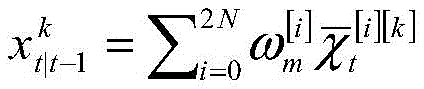

wherein, is the weight of the mean value of the Sigma points,
 variance weight of Sigma point;
updating the predicted values of the mean value and the variance according to the actual observed quantity observed by the sensing assembly at the time t:


wherein, is the Sigma point through the non-linear observation equation,
 is a predicted value of the observation that,
 is an updated vector; the cross covariance matrix and kalman gain are thus solved:


from Kalman gain and true observations ztPredicted value from observation The difference between updates the mean and variance of the mobile scanning device position:


update the Sigma point set:

the step of estimating and updating the position of the environmental feature point comprises the following steps:
constructing a Sigma point set of three-dimensional environment characteristics according to the mean value of the observed quantity, and obtaining the Sigma point set through a nonlinear observation equation

Obtaining the predicted values of the mean value and the variance of the observed values:


computing the cross-covariance, kalman gain, and updating the mean and variance of the environmental feature locations:


the step of calculating the weight of the particle and performing resampling processing comprises the following steps: the prior probability at the moment of t-1 is approximately represented by particles with weights, the particles with large weights can be classified into new particles through system observation and weight recalculation, and the particles with small weights are discarded, so that a group of new particles is obtained; and predicting the state at the time t after the new particles are added with the random quantity.
2. The mobile three-dimensional laser scanning system according to claim 1, wherein the first signal processor comprises a simultaneous localization and mapping unit, a three-dimensional point cloud registration unit and a three-dimensional modeling unit which are connected in sequence; the simultaneous positioning and drawing unit is also connected with the sensing assembly; the three-dimensional point cloud registration unit is also connected with the three-dimensional point cloud scanning instrument;
the simultaneous positioning and mapping unit is used for updating the position and posture information of the scanning center of the movable scanning equipment in real time according to the data acquired by the sensing assembly and by utilizing a simultaneous positioning and mapping algorithm;
the three-dimensional point cloud registration unit is used for registering point cloud data corresponding to any scanning center into a world coordinate system according to the real-time position and posture information of the scanning center and sending the registered data to the three-dimensional modeling unit;
and the three-dimensional modeling unit is used for carrying out three-dimensional modeling according to the point cloud data after registration.
3. The mobile three-dimensional laser scanning system of claim 1, wherein the mobile scanning device further comprises a GPS module; the GPS module is connected with the first signal processor and is used for measuring the initial scanning position of the movable scanning equipment.
4. The mobile three-dimensional laser scanning system of claim 1, wherein the sensing assembly comprises an attitude sensor, a velocity sensor, and a distance sensor.
5. The mobile three-dimensional laser scanning system of claim 1, wherein the mobile scanning device further comprises a moving mechanism and a supporting mechanism; the moving mechanism is arranged at the bottom of the supporting mechanism and is used for driving the supporting mechanism to move to each scanning position;
the three-dimensional point cloud scanning instrument is arranged on the supporting mechanism; the sensing assembly is mounted to the moving mechanism or the supporting mechanism.
6. The mobile three-dimensional laser scanning system of claim 1, wherein the three-dimensional point cloud scanning instrument is placed on top of the mobile scanning device.
7. A mobile three-dimensional laser scanning method, based on the mobile three-dimensional laser scanning system of claim 1, wherein the executing step of the first signal processor comprises:
setting initial position and attitude information of a scanning center of the movable scanning equipment;
receiving initial point cloud data scanned by the three-dimensional point cloud scanning instrument at an initial scanning position;
registering the initial point cloud data into a world coordinate system according to the initial position and posture information;
receiving data collected by the sensing assembly in real time and updating the position and posture information by utilizing a simultaneous positioning and mapping algorithm in the process that the movable scanning equipment moves to the next scanning position;
receiving another set of point cloud data scanned by the three-dimensional point cloud scanning instrument at the next scanning position;
registering the other group of point cloud data into a world coordinate system according to the position and posture information corresponding to the next scanning position;
judging whether the movable scanning equipment finishes scanning or not, and if so, performing three-dimensional modeling according to the registered point cloud data corresponding to each scanning position; otherwise, continuously executing the step of receiving the data collected by the sensing assembly in real time and updating the position and posture information by utilizing a simultaneous positioning and mapping algorithm in the process that the movable scanning equipment moves to the next scanning position.
8. A mobile three-dimensional laser scanning system is connected with a three-dimensional modeling processor, and the three-dimensional modeling processor is used for carrying out three-dimensional modeling according to data sent by the mobile three-dimensional laser scanning system; the three-dimensional point cloud scanning instrument and the sensing assembly are respectively and electrically connected with the second signal processor;
the three-dimensional point cloud scanning instrument is used for carrying out three-dimensional scanning at different scanning positions and obtaining corresponding point cloud data;
the second signal processor is used for updating the position and posture information of the scanning center of the movable scanning equipment in real time by utilizing a simultaneous localization and mapping algorithm according to the data collected by the sensing assembly, registering the point cloud data corresponding to any scanning center into a world coordinate system according to the real-time position and posture information of the scanning center, and sending the registered data to the three-dimensional modeling processor; the simultaneous localization and mapping algorithm is based on unscented Kalman filtering;
the sensing component is used for measuring various parameters required by the unscented Kalman filtering-based simultaneous positioning and mapping algorithm; all parameters required by the simultaneous positioning and mapping algorithm comprise control quantity and observed quantity; the control quantity is control information in the motion model and comprises speed or angular speed; the observed quantity is a relative pose relation between the environmental characteristic point and the current movable scanning equipment;
wherein the first signal processor updating the position and attitude information of the scanning center of the movable scanning device in real time by using the unscented kalman filter-based simultaneous localization and mapping algorithm comprises the steps of:
position estimation and updating of the mobile scanning device;
estimating and updating the position of the environmental feature point;
calculating the weight of the particles for resampling;
wherein the step of position estimation and updating of the movable scanning device comprises:
adding the position of the movable scanning device at the moment t-1, the control quantity and the noise thereof, and the observed quantity and the noise thereof into a matrix of the position and the variance of the movable scanning device:


wherein the amplification matrix A matrix having dimensions of 9 × 1, which represents information including a position, a control amount, and an observation amount of the movable scanning device at time t-1; augmented matrix
 A matrix with dimensions of 9 x 9 representing information including position variance, control noise and observation noise of the movable scanning device; wherein R istRepresenting control noise; qtRepresenting observation noise;
2n +1 Sigma points are extracted near the mean point, and the Sigma points after the Sigma points are transformed by a nonlinear motion model are solved:

wherein n is 9, utA control quantity measured at time t for the sensing assembly; is the extracted Sigma point set;
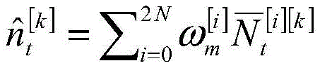
calculating the predicted value of the mean value and the variance of the position of the movable scanning device at the time t according to the weight of each Sigma point:


wherein, is the weight of the mean value of the Sigma points,
 variance weight of Sigma point;
updating the predicted values of the mean value and the variance according to the actual observed quantity observed by the sensing assembly at the time t:


wherein, is the Sigma point through the non-linear observation equation,
 is a predicted value of the observation that,
 is an updated vector; the cross covariance matrix and kalman gain are thus solved:


from Kalman gain and true observations ztPredicted value from observation The difference between updates the mean and variance of the mobile scanning device position:


update the Sigma point set:

the step of estimating and updating the position of the environmental feature point comprises the following steps:
constructing a Sigma point set of three-dimensional environment characteristics according to the mean value of the observed quantity, and obtaining the Sigma point set through a nonlinear observation equation

Obtaining the predicted values of the mean value and the variance of the observed values:


computing the cross-covariance, kalman gain, and updating the mean and variance of the environmental feature locations:


the step of calculating the weight of the particle and performing resampling processing comprises the following steps: the prior probability at the moment of t-1 is approximately represented by particles with weights, the particles with large weights can be classified into new particles through system observation and weight recalculation, and the particles with small weights are discarded, so that a group of new particles is obtained; and predicting the state at the time t after the new particles are added with the random quantity.
9. A mobile three-dimensional laser scanning method, based on the mobile three-dimensional laser scanning system of claim 8, wherein the second signal processor performs the steps of:
setting initial position and attitude information of a scanning center of the movable scanning equipment;
receiving initial point cloud data scanned at an initial scanning position by the three-dimensional point cloud data scanner;
registering the initial point cloud data into a world coordinate system according to the initial position and posture information, and sending the registered point cloud data to the three-dimensional modeling processor;
receiving data collected by the sensing assembly in real time and updating the position and posture information by utilizing a simultaneous positioning and mapping algorithm in the process that the movable scanning equipment moves to the next scanning position;
receiving another set of point cloud data scanned by the three-dimensional point cloud data scanner at the next scanning position;
registering the other group of point cloud data into a world coordinate system according to the position and posture information corresponding to the next scanning position, and sending the registered point cloud data to the three-dimensional modeling processor;
and when the movable scanning equipment is judged not to be scanned completely, continuously executing the steps of receiving the data collected by the sensing assembly in real time and updating the position and posture information by utilizing a simultaneous positioning and drawing algorithm in the process that the movable scanning equipment moves to the next scanning position.
Priority Applications (1)
| Application Number | Priority Date | Filing Date | Title |
|---|---|---|---|
| CN201610334363.8A CN105973145B (en) | 2016-05-19 | 2016-05-19 | Mobile three-dimensional laser scanning system and mobile three-dimensional laser scanning method |
Applications Claiming Priority (1)
| Application Number | Priority Date | Filing Date | Title |
|---|---|---|---|
| CN201610334363.8A CN105973145B (en) | 2016-05-19 | 2016-05-19 | Mobile three-dimensional laser scanning system and mobile three-dimensional laser scanning method |
Publications (2)
| Publication Number | Publication Date |
|---|---|
| CN105973145A CN105973145A (en) | 2016-09-28 |
| CN105973145B true CN105973145B (en) | 2021-02-05 |
Family
ID=56957019
Family Applications (1)
| Application Number | Title | Priority Date | Filing Date |
|---|---|---|---|
| CN201610334363.8A Active CN105973145B (en) | 2016-05-19 | 2016-05-19 | Mobile three-dimensional laser scanning system and mobile three-dimensional laser scanning method |
Country Status (1)
| Country | Link |
|---|---|
| CN (1) | CN105973145B (en) |
Families Citing this family (18)
| Publication number | Priority date | Publication date | Assignee | Title |
|---|---|---|---|---|
| WO2017197617A1 (en) * | 2016-05-19 | 2017-11-23 | 深圳市速腾聚创科技有限公司 | Movable three-dimensional laser scanning system and movable three-dimensional laser scanning method |
| CN106767820B (en) * | 2016-12-08 | 2017-11-14 | 立得空间信息技术股份有限公司 | A kind of indoor moving positioning and drafting method |
| CN106840179B (en) * | 2017-03-07 | 2019-12-10 | 中国科学院合肥物质科学研究院 | Intelligent vehicle positioning method based on multi-sensor information fusion |
| CN106997688B (en) * | 2017-06-08 | 2020-03-24 | 重庆大学 | Parking space detection method of parking lot based on multi-sensor information fusion |
| CN108680100B (en) * | 2018-03-07 | 2020-04-17 | 福建农林大学 | Method for matching three-dimensional laser point cloud data with unmanned aerial vehicle point cloud data |
| CN110389350B (en) * | 2018-04-16 | 2023-08-22 | 诺瓦特伦有限公司 | Earthmover, distance meter arrangement and 3D scanning method |
| CN110553598B (en) * | 2018-05-30 | 2021-03-16 | 上海辉格科技发展有限公司 | Three-dimensional laser scanning method controlled by computer |
| CN109506624B (en) * | 2018-10-31 | 2021-11-02 | 台州职业技术学院 | A distributed vision positioning system and method based on mobile robot |
| CN109459439B (en) * | 2018-12-06 | 2021-07-06 | 东南大学 | A method for detecting cracks in tunnel lining based on mobile 3D laser scanning technology |
| CN110220474B (en) * | 2019-04-30 | 2021-05-18 | 浙江华东工程安全技术有限公司 | Post attitude angle correction method for mobile laser scanning system |
| CN110186389B (en) * | 2019-05-21 | 2021-07-06 | 广东省计量科学研究院(华南国家计量测试中心) | Marker-free multi-station in-tank point cloud acquisition method and system and storage medium |
| CN111982071B (en) * | 2019-05-24 | 2022-09-27 | Tcl科技集团股份有限公司 | 3D scanning method and system based on TOF camera |
| CN110223389B (en) * | 2019-06-11 | 2021-05-04 | 中国科学院自动化研究所 | Scene modeling method, system and device for fusing image and laser data |
| CN110942514B (en) * | 2019-11-26 | 2022-11-29 | 三一重工股份有限公司 | Method, system and device for generating point cloud data and panoramic image |
| CN112688991B (en) * | 2020-12-15 | 2022-11-04 | 北京百度网讯科技有限公司 | Method, related device and storage medium for performing point cloud scanning operation |
| CN113701664A (en) * | 2021-08-04 | 2021-11-26 | 广州市运通水务有限公司 | Underground target feature rapid extraction method based on three-dimensional laser scanning technology |
| CN113689558A (en) * | 2021-08-04 | 2021-11-23 | 广州市运通水务有限公司 | Three-dimensional reconstruction system based on three-dimensional laser scanner and PCL point cloud base |
| CN115439605A (en) * | 2022-08-29 | 2022-12-06 | 中策橡胶集团股份有限公司 | Method, application, device and computer program product for track surface measurement, detection and recognition |
Family Cites Families (10)
| Publication number | Priority date | Publication date | Assignee | Title |
|---|---|---|---|---|
| CN1877253A (en) * | 2005-06-09 | 2006-12-13 | 山东科技大学 | Vehicular three-dimensional measuring system and method for close-range target |
| US9146315B2 (en) * | 2010-07-26 | 2015-09-29 | Commonwealth Scientific And Industrial Research Organisation | Three dimensional scanning beam system and method |
| US9686532B2 (en) * | 2011-04-15 | 2017-06-20 | Faro Technologies, Inc. | System and method of acquiring three-dimensional coordinates using multiple coordinate measurement devices |
| WO2012167110A2 (en) * | 2011-06-02 | 2012-12-06 | Honda Motor Co., Ltd. | Target recognition and localization methods using a laser sensor for wheeled mobile robots |
| CN103925872A (en) * | 2013-12-23 | 2014-07-16 | 中国神华能源股份有限公司 | Laser scanning measurement device and method for acquiring spatial distribution of target objects |
| CN103901895B (en) * | 2014-04-18 | 2014-10-29 | 江苏久祥汽车电器集团有限公司 | Target positioning method based on unscented FastSLAM algorithm and matching optimization and robot |
| CN104062973B (en) * | 2014-06-23 | 2016-08-24 | 西北工业大学 | A kind of mobile robot based on logos thing identification SLAM method |
| CN104180793A (en) * | 2014-08-27 | 2014-12-03 | 北京建筑大学 | Device and method for obtaining mobile spatial information for digital city construction |
| CN105258702B (en) * | 2015-10-06 | 2019-05-07 | 深圳力子机器人有限公司 | A kind of global localization method based on SLAM navigator mobile robot |
| CN105547305B (en) * | 2015-12-04 | 2018-03-16 | 北京布科思科技有限公司 | A kind of pose calculation method based on wireless location and laser map match |
-
2016
- 2016-05-19 CN CN201610334363.8A patent/CN105973145B/en active Active
Non-Patent Citations (1)
| Title |
|---|
| 基于扫描匹配的移动机器人Range-only SLAM解决方法;郭贵冰;《中国优秀硕士学位论文全文数据库信息科技辑》;20111015;I140-232 * |
Also Published As
| Publication number | Publication date |
|---|---|
| CN105973145A (en) | 2016-09-28 |
Similar Documents
| Publication | Publication Date | Title |
|---|---|---|
| CN105973145B (en) | Mobile three-dimensional laser scanning system and mobile three-dimensional laser scanning method | |
| WO2017197617A1 (en) | Movable three-dimensional laser scanning system and movable three-dimensional laser scanning method | |
| CN111060099B (en) | A real-time positioning method for unmanned vehicles | |
| CN110889808B (en) | Positioning method, device, equipment and storage medium | |
| CN107727079B (en) | Target positioning method of full-strapdown downward-looking camera of micro unmanned aerial vehicle | |
| CN111338383B (en) | GAAS-based autonomous flight method and system, and storage medium | |
| CN113495281B (en) | Real-time positioning method and device for movable platform | |
| CN112967392A (en) | Large-scale park mapping and positioning method based on multi-sensor contact | |
| JP6380936B2 (en) | Mobile body and system | |
| CN111025366B (en) | Grid SLAM navigation system and method based on INS and GNSS | |
| CN114111818B (en) | Universal vision SLAM method | |
| Hentschel et al. | A GPS and laser-based localization for urban and non-urban outdoor environments | |
| CN112164063A (en) | Data processing method and device | |
| JP2016080460A (en) | Moving body | |
| CN117387604A (en) | Positioning and mapping method and system based on 4D millimeter wave radar and IMU fusion | |
| CN110989619A (en) | Method, apparatus, device and storage medium for locating objects | |
| JP2018206038A (en) | Point group data processing device, mobile robot, mobile robot system, and point group data processing method | |
| CN117693771A (en) | Occupancy mapping for autonomous control of transportation vehicles | |
| CN113324544A (en) | Indoor mobile robot co-location method based on UWB/IMU (ultra wide band/inertial measurement unit) of graph optimization | |
| Dill et al. | Seamless indoor-outdoor navigation for unmanned multi-sensor aerial platforms | |
| CN116202509A (en) | Passable map generation method for indoor multi-layer building | |
| CN116124161A (en) | LiDAR/IMU fusion positioning method based on priori map | |
| CN117330052A (en) | Positioning and mapping methods and systems based on the fusion of infrared vision, millimeter wave radar and IMU | |
| CN117292118B (en) | Radar guided photoelectric tracking coordinate compensation method, device, electronic equipment and medium | |
| CN110794434B (en) | Pose determination method, device, equipment and storage medium |
Legal Events
| Date | Code | Title | Description |
|---|---|---|---|
| C06 | Publication | ||
| PB01 | Publication | ||
| C10 | Entry into substantive examination | ||
| SE01 | Entry into force of request for substantive examination | ||
| GR01 | Patent grant | ||
| GR01 | Patent grant |