CN116202509A - Passable map generation method for indoor multi-layer building - Google Patents
Passable map generation method for indoor multi-layer building Download PDFInfo
- Publication number
- CN116202509A CN116202509A CN202310258476.4A CN202310258476A CN116202509A CN 116202509 A CN116202509 A CN 116202509A CN 202310258476 A CN202310258476 A CN 202310258476A CN 116202509 A CN116202509 A CN 116202509A
- Authority
- CN
- China
- Prior art keywords
- coordinate system
- passable
- laser radar
- point cloud
- wheel speed
- Prior art date
- Legal status (The legal status is an assumption and is not a legal conclusion. Google has not performed a legal analysis and makes no representation as to the accuracy of the status listed.)
- Pending
Links
Images


Classifications
-
- G—PHYSICS
- G01—MEASURING; TESTING
- G01C—MEASURING DISTANCES, LEVELS OR BEARINGS; SURVEYING; NAVIGATION; GYROSCOPIC INSTRUMENTS; PHOTOGRAMMETRY OR VIDEOGRAMMETRY
- G01C21/00—Navigation; Navigational instruments not provided for in groups G01C1/00 - G01C19/00
- G01C21/38—Electronic maps specially adapted for navigation; Updating thereof
- G01C21/3804—Creation or updating of map data
- G01C21/3833—Creation or updating of map data characterised by the source of data
- G01C21/3841—Data obtained from two or more sources, e.g. probe vehicles
-
- G—PHYSICS
- G01—MEASURING; TESTING
- G01C—MEASURING DISTANCES, LEVELS OR BEARINGS; SURVEYING; NAVIGATION; GYROSCOPIC INSTRUMENTS; PHOTOGRAMMETRY OR VIDEOGRAMMETRY
- G01C21/00—Navigation; Navigational instruments not provided for in groups G01C1/00 - G01C19/00
- G01C21/10—Navigation; Navigational instruments not provided for in groups G01C1/00 - G01C19/00 by using measurements of speed or acceleration
- G01C21/12—Navigation; Navigational instruments not provided for in groups G01C1/00 - G01C19/00 by using measurements of speed or acceleration executed aboard the object being navigated; Dead reckoning
- G01C21/16—Navigation; Navigational instruments not provided for in groups G01C1/00 - G01C19/00 by using measurements of speed or acceleration executed aboard the object being navigated; Dead reckoning by integrating acceleration or speed, i.e. inertial navigation
- G01C21/165—Navigation; Navigational instruments not provided for in groups G01C1/00 - G01C19/00 by using measurements of speed or acceleration executed aboard the object being navigated; Dead reckoning by integrating acceleration or speed, i.e. inertial navigation combined with non-inertial navigation instruments
-
- G—PHYSICS
- G01—MEASURING; TESTING
- G01C—MEASURING DISTANCES, LEVELS OR BEARINGS; SURVEYING; NAVIGATION; GYROSCOPIC INSTRUMENTS; PHOTOGRAMMETRY OR VIDEOGRAMMETRY
- G01C21/00—Navigation; Navigational instruments not provided for in groups G01C1/00 - G01C19/00
- G01C21/10—Navigation; Navigational instruments not provided for in groups G01C1/00 - G01C19/00 by using measurements of speed or acceleration
- G01C21/12—Navigation; Navigational instruments not provided for in groups G01C1/00 - G01C19/00 by using measurements of speed or acceleration executed aboard the object being navigated; Dead reckoning
- G01C21/16—Navigation; Navigational instruments not provided for in groups G01C1/00 - G01C19/00 by using measurements of speed or acceleration executed aboard the object being navigated; Dead reckoning by integrating acceleration or speed, i.e. inertial navigation
- G01C21/165—Navigation; Navigational instruments not provided for in groups G01C1/00 - G01C19/00 by using measurements of speed or acceleration executed aboard the object being navigated; Dead reckoning by integrating acceleration or speed, i.e. inertial navigation combined with non-inertial navigation instruments
- G01C21/1652—Navigation; Navigational instruments not provided for in groups G01C1/00 - G01C19/00 by using measurements of speed or acceleration executed aboard the object being navigated; Dead reckoning by integrating acceleration or speed, i.e. inertial navigation combined with non-inertial navigation instruments with ranging devices, e.g. LIDAR or RADAR
-
- G—PHYSICS
- G01—MEASURING; TESTING
- G01C—MEASURING DISTANCES, LEVELS OR BEARINGS; SURVEYING; NAVIGATION; GYROSCOPIC INSTRUMENTS; PHOTOGRAMMETRY OR VIDEOGRAMMETRY
- G01C21/00—Navigation; Navigational instruments not provided for in groups G01C1/00 - G01C19/00
- G01C21/20—Instruments for performing navigational calculations
- G01C21/206—Instruments for performing navigational calculations specially adapted for indoor navigation
-
- G—PHYSICS
- G01—MEASURING; TESTING
- G01S—RADIO DIRECTION-FINDING; RADIO NAVIGATION; DETERMINING DISTANCE OR VELOCITY BY USE OF RADIO WAVES; LOCATING OR PRESENCE-DETECTING BY USE OF THE REFLECTION OR RERADIATION OF RADIO WAVES; ANALOGOUS ARRANGEMENTS USING OTHER WAVES
- G01S17/00—Systems using the reflection or reradiation of electromagnetic waves other than radio waves, e.g. lidar systems
- G01S17/86—Combinations of lidar systems with systems other than lidar, radar or sonar, e.g. with direction finders
-
- G—PHYSICS
- G01—MEASURING; TESTING
- G01S—RADIO DIRECTION-FINDING; RADIO NAVIGATION; DETERMINING DISTANCE OR VELOCITY BY USE OF RADIO WAVES; LOCATING OR PRESENCE-DETECTING BY USE OF THE REFLECTION OR RERADIATION OF RADIO WAVES; ANALOGOUS ARRANGEMENTS USING OTHER WAVES
- G01S17/00—Systems using the reflection or reradiation of electromagnetic waves other than radio waves, e.g. lidar systems
- G01S17/88—Lidar systems specially adapted for specific applications
- G01S17/89—Lidar systems specially adapted for specific applications for mapping or imaging
-
- Y—GENERAL TAGGING OF NEW TECHNOLOGICAL DEVELOPMENTS; GENERAL TAGGING OF CROSS-SECTIONAL TECHNOLOGIES SPANNING OVER SEVERAL SECTIONS OF THE IPC; TECHNICAL SUBJECTS COVERED BY FORMER USPC CROSS-REFERENCE ART COLLECTIONS [XRACs] AND DIGESTS
- Y02—TECHNOLOGIES OR APPLICATIONS FOR MITIGATION OR ADAPTATION AGAINST CLIMATE CHANGE
- Y02T—CLIMATE CHANGE MITIGATION TECHNOLOGIES RELATED TO TRANSPORTATION
- Y02T10/00—Road transport of goods or passengers
- Y02T10/10—Internal combustion engine [ICE] based vehicles
- Y02T10/40—Engine management systems
Landscapes
- Engineering & Computer Science (AREA)
- Radar, Positioning & Navigation (AREA)
- Remote Sensing (AREA)
- Physics & Mathematics (AREA)
- General Physics & Mathematics (AREA)
- Automation & Control Theory (AREA)
- Computer Networks & Wireless Communication (AREA)
- Electromagnetism (AREA)
- Navigation (AREA)
Abstract
The invention discloses a passable map generation method for indoor multi-layer buildings, which comprises the following steps: mounting a laser radar, an inertial sensor and a wheel speed odometer on the unmanned vehicle; establishing a coordinate system based on a laser radar, an inertial sensor and a wheel speed odometer, and obtaining an error state based on the coordinate system; constructing a measurement model, and measuring the multi-layer building through the measurement model to obtain point cloud data and unmanned vehicle pose data; carrying out data updating on the unmanned vehicle pose data through the obtained error state to obtain updated pose data; and generating a passable map according to the point cloud data and the updated pose data. The method adopts a tightly coupled multi-sensor fusion mode to position, so that the robustness and positioning precision of the system can be effectively improved, and the problem of environmental degradation can be effectively solved by utilizing the tightly coupled multi-sensor fusion mode aiming at structural degradation environments such as a gallery, a tunnel and the like.
Description
Technical Field
The invention belongs to the technical field of path planning, and particularly relates to a passable map generation method for indoor multi-layer buildings.
Background
The pose given by the positioning module of the traditional three-dimensional point cloud map projects the real-time point cloud or key frames to the global coordinate system, so that the point cloud map in the constructed indoor scene has poor readability, and a map user is difficult to acquire key information from the point cloud map. Although the two-dimensional map has clear structure and strong readability, the two-dimensional map cannot be used when the unmanned vehicle runs on the sloping ground or in a multi-floor environment. And the traditional laser radar is fused with the IMU/wheel speed odometer, a preliminary pose is firstly obtained through the matching process of the laser radar, and then the obtained pose is fused with the IMU and the odometer. The method is loose coupling fusion, when the laser radar is in a degradation environment, point cloud matching is wrong at the moment, the loose coupling fusion can continue to use wrong matching results for fusion, and positioning accuracy can be inevitably reduced at the moment.
Disclosure of Invention
In order to solve the technical problems, the invention provides a passable map generation method for indoor multi-layer buildings, which aims to solve the problem of positioning failure in a degradation environment.
In order to achieve the above purpose, the invention provides a method for generating a passable map for indoor multi-storey buildings, which comprises the following steps:
mounting a laser radar, an inertial sensor and a wheel speed odometer on the unmanned vehicle;
establishing a coordinate system based on a laser radar, an inertial sensor and a wheel speed odometer, and obtaining an error state based on the coordinate system;
constructing a measurement model, and measuring the multi-layer building through the measurement model to obtain point cloud data and unmanned vehicle pose data;
carrying out data updating on the unmanned vehicle pose data through the obtained error state to obtain updated pose data;
and generating a passable map according to the point cloud data and the updated pose data.
Preferably, the method for establishing a coordinate system includes:
establishing a laser radar coordinate system, an inertial sensor coordinate system, a wheel speed odometer coordinate system and a global coordinate system, and converting the laser radar coordinate system and the wheel speed odometer coordinate system into the inertial sensor coordinate system;
the origin of a coordinate system of the laser radar coordinate system is positioned at the laser radar scanning center, the X axis points to the forward scanning direction of the laser radar, the Z axis vertically upwards along the rotation axis of the laser radar, and the Y axis points to the left direction of the laser radar;
the origin of the coordinate system of the inertial sensor coordinate system is positioned at the center of the inertial sensor, the X axis points to the front direction of the unmanned vehicle, the Z axis is vertically upwards, and the Y axis points to the left direction of the unmanned vehicle;
the origin of a coordinate system of the wheel speed odometer coordinate system is positioned at the center of the unmanned vehicle, the X axis points to the front direction of the unmanned vehicle, the Z axis is vertical upwards, and the Y axis points to the left direction of the unmanned vehicle;
the global coordinate system is the inertial sensor coordinate system at the moment of starting measurement.
Preferably, the method for obtaining an error state includes:
obtaining a system input through the output of the gyroscope and the output of the accelerometer;
obtaining system noise through measuring noise of a gyroscope and an accelerometer and a random walk process of the gyroscope and the accelerometer;
acquiring a pose transformation relationship based on the system input and system noise;
and deriving the relation of the error amount through the pose transformation relation, and obtaining an error state based on the relation of the error amount.
Preferably, the method for constructing the measurement model comprises the steps of constructing a wheel speed odometer measurement model and constructing a laser radar measurement model;
the method for constructing the wheel speed odometer measuring model comprises the following steps: obtaining measurement information of the wheel speed odometer through the speed of the inertial sensor coordinate system under the global coordinate system, obtaining an observation value according to the measurement information, obtaining an observation matrix of the wheel speed odometer based on the observation value, obtaining an observation equation of the wheel speed odometer by combining measurement noise through the observation matrix, and constructing a wheel speed odometer measurement model based on the observation equation of the wheel speed odometer.
Preferably, the method for constructing the laser radar measurement model comprises the following steps:
the method comprises the steps of scanning a multi-layer building through a laser radar to obtain a three-dimensional point cloud, obtaining a characteristic point set through the three-dimensional point cloud, obtaining an observation equation of the laser radar by combining an observation value of the laser radar, and constructing a laser radar measurement model based on the observation equation of the laser radar.
Preferably, the process of generating the passable map includes:
the method comprises the steps of carrying out passable area detection according to point cloud data to obtain a passable area, and constructing a passable map by combining the passable area with updated pose data, wherein the passable area detection comprises ground passable area detection and stair detection;
the ground passable area detection process comprises the following steps: cutting point cloud data according to the installation height of the laser radar to obtain cut point cloud data, carrying out sector segmentation on the point cloud data according to the view angle of a top view, wherein the segmentation angle is the horizontal resolution of the laser radar, converting points in an area into a data structure described by a cylindrical coordinate system from a rectangular coordinate system, sequencing rays of the same segmentation angle according to the size of a radius to obtain a sequential data set, comparing adjacent three points of the rays to obtain gradients of the adjacent three points, and judging whether a detection area is a ground passable area according to the gradients.
Preferably, the stair detection process includes:
and screening a non-ground passable area data set, converting the non-ground passable area data set into a rectangular coordinate system from a cylindrical coordinate system to obtain a point cloud set, searching a stair plane based on a kicking surface, a tread surface and a stair width of the stair to obtain an initial stair plane, and screening the initial stair plane through straight line fitting to obtain a stair area.
Preferably, the process of generating the passable map includes:
and constructing a grid map based on the octomap, performing octree map ray tracing on the passable region point cloud to obtain a newly added grid and a disappearing grid in the global passable region grid map, and generating the passable map by combining the newly added grid and the disappearing grid with the pose of the unmanned vehicle under the global system.
Compared with the prior art, the invention has the following advantages and technical effects:
the method for generating the passable map for the indoor multi-layer building effectively solves the problem of accuracy reduction after environmental degradation by adopting a tightly coupled mode through combination measurement of three sensors, and effectively reduces the data storage capacity of a data map by updating the map through an octree map ray tracing method.
Drawings
The accompanying drawings, which are included to provide a further understanding of the application, illustrate and explain the application and are not to be construed as limiting the application. In the drawings:
FIG. 1 is a flow chart of a passable map generation method according to an embodiment of the present invention;
FIG. 2 is a diagram of a coordinate system and a position of a sensor according to an embodiment of the present invention;
FIG. 3 is a schematic diagram of fanning according to an embodiment of the present invention;
FIG. 4 is a schematic view of stair features according to an embodiment of the present disclosure;
fig. 5 is a schematic view of stair point cloud projection according to an embodiment of the present invention.
Detailed Description
It should be noted that, in the case of no conflict, the embodiments and features in the embodiments may be combined with each other. The present application will be described in detail below with reference to the accompanying drawings in conjunction with embodiments.
It should be noted that the steps illustrated in the flowcharts of the figures may be performed in a computer system such as a set of computer executable instructions, and that although a logical order is illustrated in the flowcharts, in some cases the steps illustrated or described may be performed in an order other than that illustrated herein.
Example 1
As shown in fig. 1, the invention provides a method for generating a passable map for indoor multi-storey buildings, which comprises the following steps:
mounting a laser radar, an inertial sensor and a wheel speed odometer on the unmanned vehicle;
establishing a coordinate system based on a laser radar, an inertial sensor and a wheel speed odometer, and obtaining an error state based on the coordinate system;
constructing a measurement model, and measuring the multi-layer building through the measurement model to obtain point cloud data and unmanned vehicle pose data;
carrying out data updating on the unmanned vehicle pose data through the obtained error state to obtain updated pose data;
and generating a passable map according to the point cloud data and the updated pose data.
Further optimizing scheme, the constructed unmanned vehicle coordinate system is shown in figure 2,
wherein the laser radar coordinate system F at the moment t L,t The definition is as follows: the origin of the coordinate system is positioned at the laser radar scanning center, the X axis points to the forward scanning direction of the laser radar, the Z axis vertically upwards along the rotation axis of the laser radar, the Y axis points to the left direction of the laser radar, the X, Y, Z axis accords with the right hand rule, the inertial sensor (IMU) outputs the angular velocity (gyroscope) and the specific force (accelerometer output) of the own coordinate system at the current moment, and the gyroscope output omega at the moment t is arranged m,t Accelerometer output is a m,t IMU system F with coordinate system t I,t The wheel speed odometer outputs the forward movement speed of the current vehicle body, and a general coordinate system F O,t The output of the wheel speed odometer at the moment t is v at the central position of the vehicle body odo,t The forward speed of the drone at time t is generally denoted s o v odo,t Wherein s is o Global coordinate system F for the scale factor of the wheel speed odometer G IMU coordinate System F defined as time 0 I,0 。
Further optimizing scheme, the relation among the sensors is as follows:
because the mounting positions of the various sensors are different, the coordinate systems of the various sensors are not completely overlapped, the coordinate systems and the positions of the various sensors at the moment t are shown in fig. 2, and all data processing is performed under the IMU coordinate system.
The wheel speed odometer and the external parameters between the laser radar and the IMU are respectively designed as And->
And-> Respectively representing the transformation matrix from the coordinate system of the two sensors to the IMU system.


Wherein the method comprises the steps of Respectively representing a rotation matrix and a translation vector of a wheel speed odometer system to an IMU system, +.>
 The rotation matrix and translation vector of the lidar system to the IMU system are shown, respectively.
When obtaining the speed measurement s of the wheel speed odometer at the time t o v odo,t At this time, the speed of switching to IMU system is Can be divided into translation speed->
 And rotational speed->


ω t The angular velocity at the time t is indicated, representing a three-dimensional vector omega t If the antisymmetric matrix of omega is set t =[ω tx ω ty ω tz ] T Then

So that

When the laser radar characteristic point is obtained at the time t When it is converted into IMU coordinate system, it gets +.>

Further optimizing scheme, the operation symbol is defined as follows:
let M be SO (3) manifold space, let its corresponding tangent space be T, then T be the space formed by three-dimensional antisymmetric array (or three-dimensional vector), let three-dimensional vector space be R 3 . Definition of the definition And->
And-> The operators are as follows:


wherein R epsilon M and R epsilon T, exp is an exponential mapping from the tangent space T to SO (3) defined by the rodrich formula,

ln (-) is the inverse mapping of Exp (-).
Further optimizing scheme, the error state calculating method is as follows:
the following state quantity is defined
 And->
And-> The IMU is a rotation matrix, translation vector and three-dimensional speed relative to a global coordinate system. b ω 、b a Zero offset for gyroscope and accelerometer, respectively.
Let the input of the system be u

Wherein omega m For output of gyroscope, a m Is the output of the accelerometer.
Assuming that the noise of the system is white noise in the Gaussian process, the noise modeling of the system is as follows:

wherein n is ω 、n a For measuring noise of gyroscope and accelerometer, n bω 、n ba Is a random walk process of a gyroscope and an accelerometer.
The motion model of IMU sets the system input and noise at i time as u i And w is equal to i The pose conversion relationship from the i time to the i+1 time is:

wherein Δt is i =t i+1 -t i For the time step from instant i to instant i +1,

error amount of the selected state herein As an estimate of the Kalman filter, then +.>
 The definition is as follows:

wherein the method comprises the steps of Represents the angular error amount, +.>
 The error amounts of the respective state amounts are represented by the state amounts minus the true value.
The relation between two time error amounts is deduced according to the relation between the i time and the i+1 time x, and the method comprises the following steps:
first, the process noise w i Set to 0, using the predicted value at time i Prediction value +.>

Then according to the state best estimated value x at the moment i i Deducing state best estimated value x at moment i+1 i+1

The error state at time i+1 can be expressed as:

wherein F is x And F is equal to w The derivation process of (2) is as follows:
first, it can be seen from 18

The same principle can be obtained:

linearizing the nonlinear parts of the two formulas to obtain:

wherein J is r The jacobian matrix is approximated for right-hand multiplication by the BCH,


at this time, the liquid crystal display device, can be expressed as

F can be obtained at this time x And F is equal to w The method comprises the following steps of:


let q=ww T As covariance matrix of noise w, covariance matrix P of error state i+1 The method comprises the following steps:
P i+1 =F x P i F x T +F w QF w T 31
the construction method of the wheel speed odometer measurement model of the further optimization scheme comprises the following steps: "
Let the output measurement information of the wheel speed speedometer at the moment i+1 be s o v odo,i+1 From the knowledge, the speed of the IMU coordinate system at the moment in the global coordinate system The method comprises the following steps:

s is then o v odo,i+1 Expressed in terms of the following state quantities:

each state quantity is represented by an error state quantity,


so s o v odo,i+1 Can be expressed as:

will s o v odo,i+1 Linearization can be achieved:

let the observed value The method comprises the following steps:

observation matrix of wheel speed odometer The method comprises the following steps: />

Let the measurement noise of the wheel speed odometer be n O The observation equation is expressed as follows:

and constructing a wheel speed mileage metering model based on the observation equation.
The laser radar measurement model construction process is as follows
According to the scanning mode of the three-dimensional laser radar, the obtained characteristic point set The corresponding feature set in the map point cloud is +.>
 When->
 In the case of planar features, v j Expressed as normal vector of its corresponding plane, the plane center coordinates are +.>
 When->
 For edge features, v j The edge direction expressed as its corresponding edge, the edge center coordinates are +.>
For any feature point The residual between it and map features is:

representing the residual error by using a state quantity and linearizing to obtain the following components:

the value of the residual should ideally be 0, but the actual situation takes into account the measurement noise n f,j The feature residuals can be expressed as follows:

setting an observation value The method comprises the following steps:

the observation equation is:

wherein the method comprises the steps of For the observation matrix, it is represented as follows,

when taking the measurement of all feature points, let

The observation equation of the lidar is expressed as follows,

and constructing a laser radar measurement model based on an observation equation of the laser radar.
Further optimizing scheme for updating unmanned vehicle state
According to the obtained IMU error state equation and wheel speed calendar/laser radar error measurement equation, the filtering gain K at the moment i+1 is the gain equation according to Kalman filtering

Wherein P is i+1 A prediction covariance matrix for the i +1 time error state, (
( or->
or-> ) For the observation matrix, R (r=n L n L T Or r=n O n O T ) Is the covariance matrix of the measured noise.
According to the error state Kalman filtering flow, the error state predicted value at the moment i+1 is considered to be 0, so the error state estimated value at the moment i+1 The method comprises the following steps:

state estimation at time i+1 The updating is as follows:

state estimation at time i+1 Is updated as:

further optimizing scheme, the process of generating the passable map comprises the following steps:
the method comprises the steps of carrying out passable area detection according to point cloud data to obtain a passable area, and constructing a passable map by combining the passable area with updated pose data, wherein the passable area detection comprises ground passable area detection and stair detection;
the method for detecting the ground passable area based on the ray geometry comprises the following steps:
is provided with For the original point cloud under the laser radar coordinate system at the moment i, as the ground point and non-ground obstacle point cloud are required to be segmented, clipping treatment is required to be carried out on the point cloud according to the installation height of the laser radar, and the clipped point cloud is obtained>
 The expression can be as follows: />

Wherein h is 1 And h 2 Is a set clipping height threshold.
Obtaining the tailored point cloud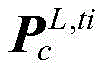 The point cloud is then fanned from a top view perspective, as shown in fig. 3.
Will be Respectively dividing into different areas S 0 ,S 1 ...S j ...S 2π/α Alpha is the segmentation angle and is typically the lidar horizontal resolution. Now in sector S j Passable area detection is performed for example. First, the point p in the region Sj (x Sj ,y Sj ,z Sj ) Data structure g described by rectangular coordinate system converted into cylindrical coordinate system col (r col ,θ col ,z Sj ) Wherein r is col And theta col The method comprises the following steps of:


since the set division angle α is small, S can be reduced j The points in the data set G are regarded as a straight line, and rays with the same included angle are sequenced according to the radius to obtain the data set G col 。
At this time G col Can be expressed as
G col ={g col,0 ,g col,1 ...g col,j ...g col,m |r col,0 <r col,1 <...r col,j <...r col,m } 57
Let p be col,j ,p col,j-1 ,p col,j-2 Is that the rays are adjacent to three points, n j-1 Is p col,j-2 And p is as follows col,j-1 Vector between two points, n j Is p col,j-1 And p is as follows col,j The vector between the two points, p col,j And p is as follows col,j-1 Slope beta of (2) j The method comprises the following steps:

at this time, whether the slope of the front and rear points of the ray is larger than a certain angle threshold epsilon can be judged to judge whether the changed point is a ground passable area point, so S j The ground points in an area can be expressed as:

thus the ground passable area P of the point cloud can be scanned at present ground The method comprises the following steps:

firstly, because the scanning range of the laser radar is wider, the data volume is larger when all point clouds in a frame are processed, and the front area of the laser radar is processed to the area of the stairsScreening to obtain data set
 Can be expressed as:

will be Converting the cylindrical coordinate system into a rectangular coordinate system to obtain a point cloud set P up After that for P up And carrying out stair plane searching. The following features are noted in the lookup process. The first-stage stairs are divided into a kicking surface P r With tread P t Two parts, wherein the normal lines of the kick surface and the pedal plane are respectively parallel and perpendicular to the X-axis direction of the laser radar, and the width of the stair is generally smaller than w, P r And P t Is Shen Xiao in h r Or depth extension Shen Xiao at d r As shown in fig. 4.
For the above feature P up Screening out the proper plane set P plane ={P plane,1 ,P plane,2 ,...P plane,j ,...P plane,l And where l is the number of planes. At this time P plane Some point clouds of the interference plane are contained, so secondary screening of the stair point clouds is required.
First, the first-time searched stair Ping Miandian cloud P plane Projecting to XZ axis plane to obtain point cloud set P line ={p line (x line ,y line ,z line )|y line =0,p line ∈P plane And as shown in fig. 5.
As can be seen from fig. 5, the projection onto the XZ axis plane yields a point cloud P line Approximately in a straight line, and thus point cloud P using least squares line The expression for straight line fitting to obtain straight line is:
A line x+B line z+C line =0 62
wherein A is line ,B line ,C line And (3) for fitting parameters of the straight line, carrying out secondary screening on the stair plane by using the fitted straight line.
First obtain P plane Center point coordinates n of each plane plane,j =(x plane,j ,y plane,j ,z plane,j ) J=1, 2,..l, calculate n plane,j Distance d to the fitted line line,j The method comprises the following steps:

d line,j less than a set distance threshold d th Is a stair point cloud P stair ,P stair Can be expressed as:
P stair ={P plane,j |d line,j <d th ,P plane,j ∈P plane } 64
wherein the distance threshold d th In connection with the characteristics of the stairs, generally less than 1m.
According to the passable regional point cloud in the multi-floor complex environment at the moment i And i pose of IMU coordinate system under global coordinate system +.>
 Converting the passable area scanned in real time into global system to obtain +.>
 Can be expressed as:


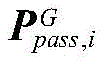
Projecting the point cloud of each passable area of each frame into the octree to form a global octree map On, and obtaining the global passable area scanned at the moment i By combining it with O n Processing is performed to obtain a new increased grid area and a reduced grid area.
Assume that Is->
Is-> One point of (a) and (b)>
 For the position of the laser radar at the moment i in the global coordinate system, { v } j The } is ∈>
 And->
And-> J sets of grids through which the laser passes. Updating the uncertainty of the grid according to the occomap grid probability updating principle to obtain:

wherein the method comprises the steps of The uncertainty corresponding to the current observation is obtained. From the above, it can be seen that->
 When larger, the person is in need of->
 The sensitivity to environmental changes is higher, and the environmental changes are detected faster at the moment, but noise interference is easy to receive; when->
 When the detection speed is lower, the sensitivity to environmental changes is lower, and at the moment, the detection of environmental changes is more stable, but the detection speed is slower. Ray tracing is carried out on all the passable area point clouds at the current moment, so that a global passable area octree map O can be obtained n Newly added grid { V ] inc,i Grid { V } and disappearing dis,i }:
{V inc,i }={v i |l(o v,i )>0.5,l(o v,i-1 )<0.5} 67
{V dis,i }={v i |l(o v,i )<0.5,l(o v,i-1 )>0.5} 68
At this time, the global passable area octree map O n The status of each grid is updated, and when the map data is required to be transmitted from the unmanned vehicle to other terminals, only O is required to be transmitted for each map transmission n Part { V of variation in (2) change Pose of unmanned vehicle under global system Wherein { V change The } can be expressed as:
{V change,i }={{V inc },{V dis }} 69
and constructing a passable area map according to the first transmitted data and the position and the pose of the unmanned vehicle under the global system by combining the part of each change.
In summary, the significant advantages of the present invention over the prior art are summarized as follows:
1) The invention can effectively solve the problem of environmental degradation by a multi-sensor fusion mode;
2) The invention uses the octree to update the map, which can realize incremental map update, and effectively reduces the memory capacity of the data map data;
3) According to the invention, a tightly coupled fusion mode is adopted, the IMU/wheel speed odometer and original characteristic point cloud data are fused, measurement information provided by the IMU and the wheel speed odometer is considered in the point cloud matching process, a comprehensive objective function of the IMU and the wheel speed odometer is constructed, and a more accurate pose estimation result is obtained.
The foregoing is merely a preferred embodiment of the present application, but the scope of the present application is not limited thereto, and any changes or substitutions easily conceivable by those skilled in the art within the technical scope of the present application should be covered in the scope of the present application. Therefore, the protection scope of the present application shall be subject to the protection scope of the claims.
Claims (8)
Priority Applications (1)
| Application Number | Priority Date | Filing Date | Title |
|---|---|---|---|
| CN202310258476.4A CN116202509A (en) | 2023-03-17 | 2023-03-17 | Passable map generation method for indoor multi-layer building |
Applications Claiming Priority (1)
| Application Number | Priority Date | Filing Date | Title |
|---|---|---|---|
| CN202310258476.4A CN116202509A (en) | 2023-03-17 | 2023-03-17 | Passable map generation method for indoor multi-layer building |
Publications (1)
| Publication Number | Publication Date |
|---|---|
| CN116202509A true CN116202509A (en) | 2023-06-02 |
Family
ID=86511240
Family Applications (1)
| Application Number | Title | Priority Date | Filing Date |
|---|---|---|---|
| CN202310258476.4A Pending CN116202509A (en) | 2023-03-17 | 2023-03-17 | Passable map generation method for indoor multi-layer building |
Country Status (1)
| Country | Link |
|---|---|
| CN (1) | CN116202509A (en) |
Cited By (4)
| Publication number | Priority date | Publication date | Assignee | Title |
|---|---|---|---|---|
| CN117146829A (en) * | 2023-10-30 | 2023-12-01 | 江苏云幕智造科技有限公司 | Multi-pose humanoid robot environment navigation method based on binocular and three-dimensional point cloud |
| CN117664101A (en) * | 2023-10-20 | 2024-03-08 | 威海广泰空港设备股份有限公司 | A lidar-based semantic slam mapping method for airport unmanned vehicles |
| CN119437200A (en) * | 2024-10-29 | 2025-02-14 | 南京北路智控科技股份有限公司 | A multi-sensor fusion positioning method, device, electronic device and storage medium for multi-layer tunnel scenes |
| WO2025167328A1 (en) * | 2024-02-05 | 2025-08-14 | 安徽蔚来智驾科技有限公司 | Positioning method, readable storage medium and smart device |
Citations (6)
| Publication number | Priority date | Publication date | Assignee | Title |
|---|---|---|---|---|
| CN106199558A (en) * | 2016-08-18 | 2016-12-07 | 宁波傲视智绘光电科技有限公司 | Barrier method for quick |
| CN111208495A (en) * | 2020-02-28 | 2020-05-29 | 燕山大学 | Ground extraction method based on laser radar point cloud characteristic line and plane calibration |
| WO2021237667A1 (en) * | 2020-05-29 | 2021-12-02 | 浙江大学 | Dense height map construction method suitable for legged robot planning |
| CN113791400A (en) * | 2021-09-07 | 2021-12-14 | 大连理工大学 | An autonomous detection method of stair parameters based on lidar |
| CN115100264A (en) * | 2022-05-12 | 2022-09-23 | 北京控制与电子技术研究所 | Terrain and target real-time detection and positioning method based on three-dimensional point cloud |
| CN115291609A (en) * | 2022-08-25 | 2022-11-04 | 七腾机器人有限公司 | A positioning and navigation method and system for an inspection robot |
-
2023
- 2023-03-17 CN CN202310258476.4A patent/CN116202509A/en active Pending
Patent Citations (6)
| Publication number | Priority date | Publication date | Assignee | Title |
|---|---|---|---|---|
| CN106199558A (en) * | 2016-08-18 | 2016-12-07 | 宁波傲视智绘光电科技有限公司 | Barrier method for quick |
| CN111208495A (en) * | 2020-02-28 | 2020-05-29 | 燕山大学 | Ground extraction method based on laser radar point cloud characteristic line and plane calibration |
| WO2021237667A1 (en) * | 2020-05-29 | 2021-12-02 | 浙江大学 | Dense height map construction method suitable for legged robot planning |
| CN113791400A (en) * | 2021-09-07 | 2021-12-14 | 大连理工大学 | An autonomous detection method of stair parameters based on lidar |
| CN115100264A (en) * | 2022-05-12 | 2022-09-23 | 北京控制与电子技术研究所 | Terrain and target real-time detection and positioning method based on three-dimensional point cloud |
| CN115291609A (en) * | 2022-08-25 | 2022-11-04 | 七腾机器人有限公司 | A positioning and navigation method and system for an inspection robot |
Non-Patent Citations (4)
| Title |
|---|
| ARMIN HORNUNG等: "OctoMap: an efficient probabilistic 3D mapping framework based on octrees", 《AUTON ROBOT 》, no. 34, 7 February 2013 (2013-02-07), pages 189 - 206 * |
| CHAO QIN等: "LINS: A Lidar-Inertial State Estimator for Robust and Efficient Navigation", 《2020 IEEE INTERNATIONAL CONFERENCE ON ROBOTICS AND AUTOMATION (ICRA). IEEE》, 15 September 2020 (2020-09-15), pages 8899 - 8905 * |
| 付相可等: "合作环境下基于惯性/里程计/Lidar融合的UGV导航方法", 《导航定位与授时》, vol. 7, no. 6, 30 November 2020 (2020-11-30), pages 94 - 101 * |
| 郑国庆: "基于激光雷达的无人车室内场景构图与三维测量技术", 《中国优秀硕士学位论文全文数据库信息科技辑》, no. 7, 15 July 2025 (2025-07-15), pages 136 - 1184 * |
Cited By (5)
| Publication number | Priority date | Publication date | Assignee | Title |
|---|---|---|---|---|
| CN117664101A (en) * | 2023-10-20 | 2024-03-08 | 威海广泰空港设备股份有限公司 | A lidar-based semantic slam mapping method for airport unmanned vehicles |
| CN117146829A (en) * | 2023-10-30 | 2023-12-01 | 江苏云幕智造科技有限公司 | Multi-pose humanoid robot environment navigation method based on binocular and three-dimensional point cloud |
| WO2025167328A1 (en) * | 2024-02-05 | 2025-08-14 | 安徽蔚来智驾科技有限公司 | Positioning method, readable storage medium and smart device |
| CN119437200A (en) * | 2024-10-29 | 2025-02-14 | 南京北路智控科技股份有限公司 | A multi-sensor fusion positioning method, device, electronic device and storage medium for multi-layer tunnel scenes |
| CN119437200B (en) * | 2024-10-29 | 2025-12-12 | 南京北路智控科技股份有限公司 | Multi-sensor fusion positioning method and device for multi-layer roadway scene, electronic equipment and storage medium |
Similar Documents
| Publication | Publication Date | Title |
|---|---|---|
| CN113781582B (en) | Synchronous positioning and map creation method based on joint calibration of lidar and inertial navigation | |
| CN114526745B (en) | Drawing construction method and system for tightly coupled laser radar and inertial odometer | |
| CN112880674B (en) | A method, device, equipment and storage medium for positioning a traveling device | |
| CN116202509A (en) | Passable map generation method for indoor multi-layer building | |
| CN113654555A (en) | Automatic driving vehicle high-precision positioning method based on multi-sensor data fusion | |
| CN113052855B (en) | Semantic SLAM method based on visual-IMU-wheel speed meter fusion | |
| Barczyk et al. | Invariant EKF design for scan matching-aided localization | |
| Zhou et al. | A lidar odometry for outdoor mobile robots using ndt based scan matching in gps-denied environments | |
| CN117387604A (en) | Positioning and mapping method and system based on 4D millimeter wave radar and IMU fusion | |
| CN110895408B (en) | Autonomous positioning method and device and mobile robot | |
| CN118010014B (en) | Multi-source heterogeneous information fusion positioning method for complex pipeline environment based on subgraph matching | |
| CN108195376A (en) | Small drone Camera calibration method | |
| CN117629187A (en) | Tightly coupled odometry method and system based on UWB and vision fusion | |
| CN118031983B (en) | Automatic driving fusion positioning method and system | |
| CN117705104A (en) | Robust autonomous positioning and mapping method, device and medium based on UWB and IMU fusion | |
| CN117250630A (en) | Multi-sensor fusion positioning system and method based on adaptive kernel Kalman filter | |
| CN119335552A (en) | A LiDAR-IMU calibration algorithm for underground confined spaces | |
| CN117760417A (en) | A fusion positioning method and system based on 4D millimeter wave radar and IMU | |
| Li et al. | Aerial-triangulation aided boresight calibration for a low-cost UAV-LiDAR system | |
| CN120195712A (en) | Multi-source data fusion positioning method based on low-orbit satellite assistance | |
| CN120160608A (en) | A mapping method, device, robot and storage medium | |
| Bai et al. | A sensor fusion framework using multiple particle filters for video-based navigation | |
| CN118149796B (en) | Map construction method and device under degradation environment, electronic equipment and storage medium | |
| Deusch et al. | Improving localization in digital maps with grid maps | |
| CN111141290B (en) | Positioning methods, positioning devices, equipment and storage media for robots |
Legal Events
| Date | Code | Title | Description |
|---|---|---|---|
| PB01 | Publication | ||
| PB01 | Publication | ||
| SE01 | Entry into force of request for substantive examination | ||
| SE01 | Entry into force of request for substantive examination |