CN103206262A - Airfoil - Google Patents
Airfoil Download PDFInfo
- Publication number
- CN103206262A CN103206262A CN2013100100429A CN201310010042A CN103206262A CN 103206262 A CN103206262 A CN 103206262A CN 2013100100429 A CN2013100100429 A CN 2013100100429A CN 201310010042 A CN201310010042 A CN 201310010042A CN 103206262 A CN103206262 A CN 103206262A
- Authority
- CN
- China
- Prior art keywords
- airfoil
- segment
- pressure side
- trench
- suction side
- Prior art date
- Legal status (The legal status is an assumption and is not a legal conclusion. Google has not performed a legal analysis and makes no representation as to the accuracy of the status listed.)
- Granted
Links
Images


Classifications
-
- F—MECHANICAL ENGINEERING; LIGHTING; HEATING; WEAPONS; BLASTING
- F01—MACHINES OR ENGINES IN GENERAL; ENGINE PLANTS IN GENERAL; STEAM ENGINES
- F01D—NON-POSITIVE DISPLACEMENT MACHINES OR ENGINES, e.g. STEAM TURBINES
- F01D5/00—Blades; Blade-carrying members; Heating, heat-insulating, cooling or antivibration means on the blades or the members
- F01D5/12—Blades
- F01D5/14—Form or construction
- F01D5/18—Hollow blades, i.e. blades with cooling or heating channels or cavities; Heating, heat-insulating or cooling means on blades
- F01D5/186—Film cooling
-
- F—MECHANICAL ENGINEERING; LIGHTING; HEATING; WEAPONS; BLASTING
- F05—INDEXING SCHEMES RELATING TO ENGINES OR PUMPS IN VARIOUS SUBCLASSES OF CLASSES F01-F04
- F05D—INDEXING SCHEME FOR ASPECTS RELATING TO NON-POSITIVE-DISPLACEMENT MACHINES OR ENGINES, GAS-TURBINES OR JET-PROPULSION PLANTS
- F05D2240/00—Components
- F05D2240/20—Rotors
- F05D2240/30—Characteristics of rotor blades, i.e. of any element transforming dynamic fluid energy to or from rotational energy and being attached to a rotor
- F05D2240/303—Characteristics of rotor blades, i.e. of any element transforming dynamic fluid energy to or from rotational energy and being attached to a rotor related to the leading edge of a rotor blade
-
- F—MECHANICAL ENGINEERING; LIGHTING; HEATING; WEAPONS; BLASTING
- F05—INDEXING SCHEMES RELATING TO ENGINES OR PUMPS IN VARIOUS SUBCLASSES OF CLASSES F01-F04
- F05D—INDEXING SCHEME FOR ASPECTS RELATING TO NON-POSITIVE-DISPLACEMENT MACHINES OR ENGINES, GAS-TURBINES OR JET-PROPULSION PLANTS
- F05D2240/00—Components
- F05D2240/80—Platforms for stationary or moving blades
- F05D2240/81—Cooled platforms
-
- F—MECHANICAL ENGINEERING; LIGHTING; HEATING; WEAPONS; BLASTING
- F05—INDEXING SCHEMES RELATING TO ENGINES OR PUMPS IN VARIOUS SUBCLASSES OF CLASSES F01-F04
- F05D—INDEXING SCHEME FOR ASPECTS RELATING TO NON-POSITIVE-DISPLACEMENT MACHINES OR ENGINES, GAS-TURBINES OR JET-PROPULSION PLANTS
- F05D2250/00—Geometry
- F05D2250/30—Arrangement of components
- F05D2250/32—Arrangement of components according to their shape
- F05D2250/324—Arrangement of components according to their shape divergent
-
- F—MECHANICAL ENGINEERING; LIGHTING; HEATING; WEAPONS; BLASTING
- F05—INDEXING SCHEMES RELATING TO ENGINES OR PUMPS IN VARIOUS SUBCLASSES OF CLASSES F01-F04
- F05D—INDEXING SCHEME FOR ASPECTS RELATING TO NON-POSITIVE-DISPLACEMENT MACHINES OR ENGINES, GAS-TURBINES OR JET-PROPULSION PLANTS
- F05D2260/00—Function
- F05D2260/20—Heat transfer, e.g. cooling
- F05D2260/202—Heat transfer, e.g. cooling by film cooling
Landscapes
- Engineering & Computer Science (AREA)
- Mechanical Engineering (AREA)
- General Engineering & Computer Science (AREA)
- Turbine Rotor Nozzle Sealing (AREA)
Abstract
Description
技术领域 technical field
本发明大体上涉及例如可在涡轮机中使用的翼型件。 The present invention generally relates to airfoils such as may be used in turbomachines.
背景技术 Background technique
涡轮机在各种航空、工业和发电应用中广泛地用于进行作业。每种涡轮机一般包括周边安装的定子导叶和旋转叶片的交替级。每个定子导叶和旋转叶片可包括成形为翼型件的高合金钢和/或陶瓷材料,并且诸如蒸汽、燃烧气体或空气的压缩工作流体沿涡轮机中的气体路径流过定子导叶和旋转叶片。定子导叶将压缩工作流体加速并引导到旋转叶片的后续级上,以向旋转叶片赋予运动并进行作业。 Turbines are widely used to perform work in a variety of aerospace, industrial, and power generation applications. Each type of turbine typically includes alternating stages of circumferentially mounted stator vanes and rotating blades. Each stator vane and rotating blade may comprise high-alloy steel and/or ceramic material shaped into an airfoil, and a compressed working fluid such as steam, combustion gas, or air flows through the stator vane and rotates along the gas path in the turbine. blade. The stator vanes accelerate and direct the compressed working fluid onto subsequent stages of rotating blades to impart motion and work to the rotating blades.
与压缩工作流体相关联的高温可引起定子导叶和/或旋转叶片的增加的磨损和/或损坏。结果,冷却介质可供应到翼型件内部且通过翼型件释放,以向翼型件的外侧提供薄膜冷却。翼型件中的沟槽(trench)跨翼型件的外表面均匀地分配冷却介质。然而,改变冷却介质跨翼型件的外表面的分配的改进翼型件将是有用的。 High temperatures associated with compressing the working fluid may cause increased wear and/or damage to the stator vanes and/or rotating blades. As a result, a cooling medium may be supplied to the interior of the airfoil and released through the airfoil to provide film cooling to the outside of the airfoil. Trench in the airfoil distributes the cooling medium evenly across the outer surface of the airfoil. However, improved airfoils that alter the distribution of cooling medium across the outer surface of the airfoil would be useful.
发明内容 Contents of the invention
本发明的方面和优点阐述在以下描述中,或可从该描述显而易见,或者可通过实践本发明来了解。 Aspects and advantages of the invention are set forth in the following description, or may be obvious from the description, or may be learned by practice of the invention.
本发明的一个实施例是一种翼型件,其包括内表面和与该内表面相反的外表面。外表面包括压力侧、与压力侧相反的吸力侧、在压力侧和吸力侧之间的滞止线以及在压力侧和吸力侧之间且在滞止线下游的后缘。多个沟槽段位于外表面上,并且每个沟槽段延伸小于外表面的长度的50%。每个沟槽段中的冷却通路提供从内表面到外表面的流体连通。 One embodiment of the invention is an airfoil including an inner surface and an outer surface opposite the inner surface. The outer surface includes a pressure side, a suction side opposite the pressure side, a stagnation line between the pressure side and the suction side, and a trailing edge between the pressure side and the suction side and downstream of the stagnation line. A plurality of groove segments are located on the outer surface, and each groove segment extends less than 50% of the length of the outer surface. Cooling passages in each trench segment provide fluid communication from the inner surface to the outer surface.
本发明的另一实施例是一种翼型件,其包括平台和连接至该平台的外表面。多个沟槽段位于外表面上,并且每个沟槽段延伸小于外表面的长度的50%。每个沟槽段中的冷却通路向外表面供应冷却介质。 Another embodiment of the invention is an airfoil including a platform and an outer surface connected to the platform. A plurality of groove segments are located on the outer surface, and each groove segment extends less than 50% of the length of the outer surface. Cooling passages in each trench segment supply cooling medium to the outer surface.
在又一实施例中,一种翼型件包括内表面和与该内表面相反的外表面。外表面包括压力侧、与压力侧相反的吸力侧、在压力侧和吸力侧之间的滞止线以及在压力侧和吸力侧之间且在滞止线下游的后缘。在压力侧、吸力侧、滞止线或后缘中的至少一个上的沟槽段延伸小于外表面的长度的50%。沟槽段中的冷却通路提供从内表面到外表面的流体连通。 In yet another embodiment, an airfoil includes an inner surface and an outer surface opposite the inner surface. The outer surface includes a pressure side, a suction side opposite the pressure side, a stagnation line between the pressure side and the suction side, and a trailing edge between the pressure side and the suction side and downstream of the stagnation line. The groove segment on at least one of the pressure side, suction side, stagnation line or trailing edge extends less than 50% of the length of the outer surface. Cooling passages in the trench segments provide fluid communication from the inner surface to the outer surface.
在本发明的另一实施例中,一种翼型件包括内表面和与该内表面相反的外表面,其中,外表面包括压力侧、与压力侧相反的吸力侧、在压力侧和吸力侧之间的滞止线以及在压力侧和吸力侧之间且在滞止线下游的后缘。平台或侧壁中的至少一个与外表面相邻。一个或更多沟槽段位于平台或侧壁上,其中,每个沟槽段延伸小于外表面的长度的50%,并且冷却通道位于每个沟槽段中。 In another embodiment of the invention, an airfoil includes an inner surface and an outer surface opposite the inner surface, wherein the outer surface includes a pressure side, a suction side opposite the pressure side, a pressure side and a suction side The stagnation line between and the trailing edge between the pressure side and the suction side and downstream of the stagnation line. At least one of the platform or the sidewall is adjacent the outer surface. One or more groove segments are located on the platform or sidewall, wherein each groove segment extends less than 50% of the length of the outer surface, and a cooling channel is located in each groove segment.
通过阅读该说明书,本领域的普通技术人员将更好地理解此类实施例的特征和方面及其它。 Those of ordinary skill in the art will better understand the features and aspects of such embodiments, among others, from reading this specification.
附图说明 Description of drawings
在说明书的剩余部分中,包括参考附图,更具体地阐述了本发明的完整且能够实现的公开内容,包括对本领域技术人员而言的其最佳模式,在附图中: In the remainder of the specification, a full and enabling disclosure of the invention, including its best mode to those skilled in the art, is set forth more particularly, including with reference to the accompanying drawings, in which:
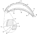
图1是根据本发明的一个实施例的翼型件的透视图; Figure 1 is a perspective view of an airfoil according to one embodiment of the invention;
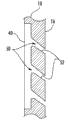
图2是图1中所示的翼型件沿线A-A截取的轴向截面图; Figure 2 is an axial sectional view of the airfoil shown in Figure 1 taken along line A-A;
图3是图1中所示的翼型件沿线B-B截取的径向截面图; Figure 3 is a radial sectional view of the airfoil shown in Figure 1 taken along line B-B;
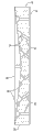
图4是根据本发明的第二实施例的翼型件的透视图; Figure 4 is a perspective view of an airfoil according to a second embodiment of the invention;
图5是根据本发明的第三实施例的翼型件的透视图;以及 Figure 5 is a perspective view of an airfoil according to a third embodiment of the invention; and
图6是图5中所示的翼型件沿线C-C截取的径向截面图。 FIG. 6 is a radial cross-sectional view of the airfoil shown in FIG. 5 taken along line C-C.
附图标记: Reference signs:
10 翼型件 10 airfoils
12 平台 12 platforms
16 内表面 16 inner surface
18 外表面 18 outer surface
20 压力侧 20 pressure side
22 吸力侧 22 Suction side
24 滞止区域 24 stagnant area
26 后缘 26 trailing edge
30 径向长度 30 radial length
32 轴向长度 32 axial length
40 沟槽段 40 Groove Sections
42 壁 42 wall
50 冷却通路 50 cooling channels
52 第一区段 52 first segment
54 第二区段。 54 Second section.
具体实施方式 Detailed ways
现在将详细提及本发明的当前实施例,其一个或更多示例在附图中示出。详细描述使用数字和字母标号来指代附图中的特征。已在附图和描述中使用相同或类似的标号来指代本发明的相同或类似的部分。如文中所用,用语“第一”、“第二”和“第三”可互换使用以区分一个构件与另一个且并不意图表示各个构件的位置或重要性。此外,用语“上游”和“下游”指的是构件在流体路径中的相对位置。例如,如果流体从构件A流向构件B,则构件A在构件B的上游。相反,如果构件B从构件A接收流体流,则构件B在构件A的下游。 Reference will now be made in detail to the present embodiments of the invention, one or more examples of which are illustrated in the accompanying drawings. The detailed description uses numerical and letter designations to refer to features in the drawings. The same or similar reference numerals have been used in the drawings and description to refer to the same or similar parts of the present invention. As used herein, the terms "first," "second," and "third" are used interchangeably to distinguish one element from another and are not intended to indicate the position or importance of the various elements. Additionally, the terms "upstream" and "downstream" refer to the relative position of components in a fluid pathway. For example, if fluid flows from component A to component B, then component A is upstream of component B. Conversely, component B is downstream of component A if component B receives fluid flow from component A.
以本发明的说明而非本发明的限制的方式来提供每个示例。事实上,对本领域技术人员而言将显而易见的是,可在本发明中做出修改和变型而不脱离其范围或精神。例如,作为一个实施例的一部分所示出或描述的特征可用于另一实施例上以产生再一实施例。因此,本发明意图覆盖落入所附权利要求及其等同的范围内的此类修改和变型。 Each example is provided by way of explanation of the invention, not limitation of the invention. In fact, it will be apparent to those skilled in the art that modifications and variations can be made in the present invention without departing from its scope or spirit. For example, features illustrated or described as part of one embodiment can be used on another embodiment to yield a still further embodiment. Thus, it is intended that the present invention covers such modifications and variations as come within the scope of the appended claims and their equivalents.
图1提供了根据本发明的一个实施例的翼型件10的透视图,并且图2和图3分别提供了图1中所示的翼型件10沿线A-A和B-B截取的轴向和径向截面图。翼型件10可例如被用作涡轮机中的旋转叶片或静止导叶,以将与压缩工作流体相关联的动能转化成机械能。压缩工作流体可为具有动能的蒸汽、燃烧气体、空气或任何其它流体。如图1至图3中所示,翼型件10一般连接至平台或侧壁12。平台或侧壁12一般用作涡轮机内部的气体路径的径向边界并且为翼型件10提供附连点。翼型件10可包括内表面16和与内表面16相反且连接至平台12的外表面18。外表面一般包括压力侧20和与压力侧20相反的吸力侧22。如图1和图2中所示,压力侧20一般是凹形的,而吸力侧22一般是凸形的,以提供压缩工作流体流过的空气动力学表面。在压力侧20和吸力侧22之间的翼型件10的前缘处的滞止线24代表外表面18上一般具有最高温度的位置。后缘24在压力侧20和吸力侧22之间且在滞止线24的下游。这样,外表面18形成适合于将与压缩工作流体相关联的动能转化成机械能的空气动力学表面。
Figure 1 provides a perspective view of an
外表面18一般包括从平台12延伸的径向长度30和从滞止线24延伸到后缘26的轴向长度32。一个或更多沟槽段40在外表面18中径向和/或轴向地延伸,并且每个沟槽段40包括提供从内表面16到外表面18的流体连通的一个或更多冷却通路50。这样,冷却介质可被供应至翼型件旋转叶片10的内部,并且冷却通路50允许冷却介质流动通过翼型件10以向外表面18提供薄膜冷却。
沟槽段40可位于翼型件10和/或平台或侧壁12上的任何部位,并且每个沟槽段40延伸小于外表面18的径向长度30和/或轴向长度32的50%。此外,沟槽段40可具有均匀或变化的长度,可以是直的或弓形的,并且可相对于彼此对齐或错开。例如,如图1中所示,沟槽段40可成列和/或行布置在平台或侧壁12、压力侧20和滞止线24上。备选地或另外,沟槽段40可位于吸力侧22和/或后缘26中。在图1所示的特定实施例中,每个沟槽段40基本上是直的且沿外表面18径向延伸。此外,相邻列中的沟槽段40具有不同长度且相对于彼此错开,使得相邻列中的沟槽段40的端部不重合。这样,多行沟槽段40彼此重叠以增强流动通过冷却通路50的冷却介质的径向分配。在备选实施例中,沟槽段40的长度可变大至外表面18的整个径向长度30。
The
如图2和图3中最清楚地示出的,每个沟槽段40一般包括在外表面18中限定凹部或凹槽的相对的壁42。相对的壁42可以是直的或弯曲的,并且可为沟槽段40限定一致或变化的宽度。相邻沟槽段40中的冷却通路50可彼此对齐或偏离。每个冷却通路50可包括终止于内表面16的第一区段52和终止于外表面18的第二区段54。第一区段52可具有圆柱形形状,并且第二区段54可具有圆锥形或球形形状。如图3中所示,第一区段52可相对于第二区段54和/或沟槽段40成角度,以提供流动通过冷却通路50且到沟槽段40中的冷却介质的定向流动。备选地或另外,沟槽段40的第二区段54和/或壁42可为不对称的,以优先跨外表面18分配冷却介质。
As shown most clearly in FIGS. 2 and 3 , each
图4提供了根据本发明的第二实施例的翼型件10的透视图。如图所示,翼型件10同样包括如以上关于图1至图3所述的平台12、沟槽段40和冷却通路50。在该特定实施例中,沟槽段40是弯曲的或弓形的,并且沿外表面18在宽度和/或深度上变化。弯曲的沟槽段40和变化的宽度和/或深度改变了冷却介质跨外表面18的分配。例如,弯曲的沟槽段40允许冷却介质转向,以允许流覆盖外表面18的更多部分。
Figure 4 provides a perspective view of an
图5提供了根据本发明的第三实施例的翼型件10的透视图,并且图6提供了图5中所示的翼型件10沿线C-C截取的径向截面图。如图所示,翼型件10同样包括如以上关于图1至图3所述的平台12、沟槽段40和冷却通路50。在该特定实施例中,沟槽段40是直的,具有基本均匀的长度,并且沿外表面18径向延伸。此外,每个沟槽段40具有变化的宽度和/或深度,并且如图6中最清楚示出的,一个或更多冷却通路50朝向沟槽段40的增大的宽度和/或减小的深度成角度。具体而言,一个或更多冷却通路50中的第一区段52和/或第二区段54朝向沟槽段40的较宽和/或较浅部分成角度。这样,成角度的冷却通路50优先将冷却介质引导至沟槽段40的较宽和/或较浅部分,以同样增强冷却介质沿外表面18的分配。
FIG. 5 provides a perspective view of an
该书面描述使用示例来公开本发明,包括最佳模式,并且还使本领域的任何技术人员能够实践本发明,包括制造和使用任何装置或系统以及执行任何并入的方法。本发明的可专利权范围由权利要求限定,并且可包括本领域技术人员想到的其它示例。如果此类其它示例包括与权利要求的文字语言没有区别的结构元件,或者如果它们包括与权利要求的文字语言无实质性区别的等同结构元件,则认为此类其它示例在权利要求的范围内。 This written description uses examples to disclose the invention, including the best mode, and also to enable any person skilled in the art to practice the invention, including making and using any devices or systems and performing any incorporated methods. The patentable scope of the invention is defined by the claims, and may include other examples that occur to those skilled in the art. Such other examples are intended to be within the scope of the claims if they include structural elements that do not differ from the literal language of the claims, or if they include equivalent structural elements with insubstantial differences from the literal language of the claims.
Claims (21)
Applications Claiming Priority (3)
| Application Number | Priority Date | Filing Date | Title |
|---|---|---|---|
| US13/349,862 | 2012-01-13 | ||
| US13/349,862 US8870536B2 (en) | 2012-01-13 | 2012-01-13 | Airfoil |
| US13/349862 | 2012-01-13 |
Publications (2)
| Publication Number | Publication Date |
|---|---|
| CN103206262A true CN103206262A (en) | 2013-07-17 |
| CN103206262B CN103206262B (en) | 2016-08-03 |
Family
ID=47631265
Family Applications (1)
| Application Number | Title | Priority Date | Filing Date |
|---|---|---|---|
| CN201310010042.9A Active CN103206262B (en) | 2012-01-13 | 2013-01-11 | airfoil |
Country Status (5)
| Country | Link |
|---|---|
| US (1) | US8870536B2 (en) |
| EP (1) | EP2615244B1 (en) |
| JP (1) | JP6110666B2 (en) |
| CN (1) | CN103206262B (en) |
| RU (1) | RU2013100410A (en) |
Cited By (2)
| Publication number | Priority date | Publication date | Assignee | Title |
|---|---|---|---|---|
| CN103527260A (en) * | 2012-06-28 | 2014-01-22 | 通用电气公司 | Airfoil |
| CN106050317A (en) * | 2015-04-13 | 2016-10-26 | 通用电气公司 | Turbine airfoil |
Families Citing this family (16)
| Publication number | Priority date | Publication date | Assignee | Title |
|---|---|---|---|---|
| DE102013109116A1 (en) * | 2012-08-27 | 2014-03-27 | General Electric Company (N.D.Ges.D. Staates New York) | Component with cooling channels and method of manufacture |
| WO2015047516A1 (en) * | 2013-07-03 | 2015-04-02 | General Electric Company | Trench cooling of airfoil structures |
| US9416662B2 (en) * | 2013-09-03 | 2016-08-16 | General Electric Company | Method and system for providing cooling for turbine components |
| US10329921B2 (en) * | 2014-10-24 | 2019-06-25 | United Technologies Corporation | Cooling configuration for a component |
| KR101839656B1 (en) * | 2015-08-13 | 2018-04-26 | 두산중공업 주식회사 | Blade for turbine |
| DE102016203388A1 (en) * | 2016-03-02 | 2017-09-07 | Siemens Aktiengesellschaft | Coating system with coating recess on cooling air holes of turbine blades |
| KR101853550B1 (en) * | 2016-08-22 | 2018-04-30 | 두산중공업 주식회사 | Gas Turbine Blade |
| US10577942B2 (en) | 2016-11-17 | 2020-03-03 | General Electric Company | Double impingement slot cap assembly |
| US20180230812A1 (en) * | 2017-01-13 | 2018-08-16 | General Electric Company | Film hole arrangement for a turbine engine |
| FR3070714B1 (en) * | 2017-09-01 | 2020-09-18 | Safran Aircraft Engines | TURBOMACHINE VANE WITH IMPROVED COOLING HOLES |
| US10570747B2 (en) * | 2017-10-02 | 2020-02-25 | DOOSAN Heavy Industries Construction Co., LTD | Enhanced film cooling system |
| US20190218917A1 (en) * | 2018-01-17 | 2019-07-18 | General Electric Company | Engine component with set of cooling holes |
| US11401818B2 (en) * | 2018-08-06 | 2022-08-02 | General Electric Company | Turbomachine cooling trench |
| GB201819064D0 (en) | 2018-11-23 | 2019-01-09 | Rolls Royce | Aerofoil stagnation zone cooling |
| RU197365U1 (en) * | 2020-02-04 | 2020-04-23 | Федеральное государственное бюджетное образовательное учреждение высшего образования "Рыбинский государственный авиационный технический университет имени П.А. Соловьева" | FILM COOLED GAS TURBINE ELEMENT |
| US12607125B2 (en) * | 2021-02-05 | 2026-04-21 | Nikon Corporation | Blade member and structural member |
Citations (8)
| Publication number | Priority date | Publication date | Assignee | Title |
|---|---|---|---|---|
| JPS58197402A (en) * | 1982-05-14 | 1983-11-17 | Hitachi Ltd | gas turbine blade |
| GB8707300D0 (en) * | 1987-03-26 | 1987-04-29 | Secr Defence | Cooled aerofoil components |
| CN86108855A (en) * | 1985-12-23 | 1987-07-22 | 联合工艺公司 | Method for fabricating film cooling slots on hollow airfoils |
| CN1235654A (en) * | 1996-10-31 | 1999-11-17 | 普拉特&惠特尼加拿大公司 | Cooling channels for airfoil leading edge |
| EP1013877A2 (en) * | 1998-12-21 | 2000-06-28 | United Technologies Corporation | Hollow airfoil for a gas turbine engine |
| US7540712B1 (en) * | 2006-09-15 | 2009-06-02 | Florida Turbine Technologies, Inc. | Turbine airfoil with showerhead cooling holes |
| US20100040478A1 (en) * | 2008-08-14 | 2010-02-18 | United Technologies Corp. | Cooled Airfoils and Gas Turbine Engine Systems Involving Such Airfoils |
| US20100266410A1 (en) * | 2009-04-17 | 2010-10-21 | General Electric Company | Rotor blades for turbine engines |
Family Cites Families (22)
| Publication number | Priority date | Publication date | Assignee | Title |
|---|---|---|---|---|
| US2613910A (en) * | 1947-01-24 | 1952-10-14 | Edward A Stalker | Slotted turbine blade |
| US3515499A (en) * | 1968-04-22 | 1970-06-02 | Aerojet General Co | Blades and blade assemblies for turbine engines,compressors and the like |
| GB1209692A (en) * | 1968-05-14 | 1970-10-21 | Rolls Royce | Method and apparatus for the spark-machining of workpieces and a spark-machining electrode for use therein |
| US5486093A (en) * | 1993-09-08 | 1996-01-23 | United Technologies Corporation | Leading edge cooling of turbine airfoils |
| US5374162A (en) | 1993-11-30 | 1994-12-20 | United Technologies Corporation | Airfoil having coolable leading edge region |
| US5458461A (en) | 1994-12-12 | 1995-10-17 | General Electric Company | Film cooled slotted wall |
| US6050777A (en) * | 1997-12-17 | 2000-04-18 | United Technologies Corporation | Apparatus and method for cooling an airfoil for a gas turbine engine |
| US6210111B1 (en) | 1998-12-21 | 2001-04-03 | United Technologies Corporation | Turbine blade with platform cooling |
| DE50009497D1 (en) * | 2000-11-16 | 2005-03-17 | Siemens Ag | Film cooling of gas turbine blades by means of slots for cooling air |
| US6994521B2 (en) * | 2003-03-12 | 2006-02-07 | Florida Turbine Technologies, Inc. | Leading edge diffusion cooling of a turbine airfoil for a gas turbine engine |
| US6955522B2 (en) * | 2003-04-07 | 2005-10-18 | United Technologies Corporation | Method and apparatus for cooling an airfoil |
| US20070141385A1 (en) * | 2005-12-21 | 2007-06-21 | General Electric Company | Method of coating gas turbine components |
| US7510367B2 (en) * | 2006-08-24 | 2009-03-31 | Siemens Energy, Inc. | Turbine airfoil with endwall horseshoe cooling slot |
| US7553534B2 (en) * | 2006-08-29 | 2009-06-30 | General Electric Company | Film cooled slotted wall and method of making the same |
| US7980819B2 (en) * | 2007-03-14 | 2011-07-19 | United Technologies Corporation | Cast features for a turbine engine airfoil |
| US8092176B2 (en) * | 2008-09-16 | 2012-01-10 | Siemens Energy, Inc. | Turbine airfoil cooling system with curved diffusion film cooling hole |
| US8057182B2 (en) * | 2008-11-21 | 2011-11-15 | General Electric Company | Metered cooling slots for turbine blades |
| US8109725B2 (en) * | 2008-12-15 | 2012-02-07 | United Technologies Corporation | Airfoil with wrapped leading edge cooling passage |
| US20110097188A1 (en) * | 2009-10-23 | 2011-04-28 | General Electric Company | Structure and method for improving film cooling using shallow trench with holes oriented along length of trench |
| US8608443B2 (en) * | 2010-06-11 | 2013-12-17 | Siemens Energy, Inc. | Film cooled component wall in a turbine engine |
| US8628293B2 (en) * | 2010-06-17 | 2014-01-14 | Honeywell International Inc. | Gas turbine engine components with cooling hole trenches |
| JP5636774B2 (en) * | 2010-07-09 | 2014-12-10 | 株式会社Ihi | Turbine blades and engine parts |
-
2012
- 2012-01-13 US US13/349,862 patent/US8870536B2/en active Active
-
2013
- 2013-01-08 JP JP2013000769A patent/JP6110666B2/en active Active
- 2013-01-09 EP EP13150621.4A patent/EP2615244B1/en active Active
- 2013-01-10 RU RU2013100410/06A patent/RU2013100410A/en not_active Application Discontinuation
- 2013-01-11 CN CN201310010042.9A patent/CN103206262B/en active Active
Patent Citations (9)
| Publication number | Priority date | Publication date | Assignee | Title |
|---|---|---|---|---|
| JPS58197402A (en) * | 1982-05-14 | 1983-11-17 | Hitachi Ltd | gas turbine blade |
| CN86108855A (en) * | 1985-12-23 | 1987-07-22 | 联合工艺公司 | Method for fabricating film cooling slots on hollow airfoils |
| GB8707300D0 (en) * | 1987-03-26 | 1987-04-29 | Secr Defence | Cooled aerofoil components |
| GB2202907A (en) * | 1987-03-26 | 1988-10-05 | Secr Defence | Cooled aerofoil components |
| CN1235654A (en) * | 1996-10-31 | 1999-11-17 | 普拉特&惠特尼加拿大公司 | Cooling channels for airfoil leading edge |
| EP1013877A2 (en) * | 1998-12-21 | 2000-06-28 | United Technologies Corporation | Hollow airfoil for a gas turbine engine |
| US7540712B1 (en) * | 2006-09-15 | 2009-06-02 | Florida Turbine Technologies, Inc. | Turbine airfoil with showerhead cooling holes |
| US20100040478A1 (en) * | 2008-08-14 | 2010-02-18 | United Technologies Corp. | Cooled Airfoils and Gas Turbine Engine Systems Involving Such Airfoils |
| US20100266410A1 (en) * | 2009-04-17 | 2010-10-21 | General Electric Company | Rotor blades for turbine engines |
Cited By (4)
| Publication number | Priority date | Publication date | Assignee | Title |
|---|---|---|---|---|
| CN103527260A (en) * | 2012-06-28 | 2014-01-22 | 通用电气公司 | Airfoil |
| CN103527260B (en) * | 2012-06-28 | 2017-03-01 | 通用电气公司 | Aerofoil profile |
| CN106050317A (en) * | 2015-04-13 | 2016-10-26 | 通用电气公司 | Turbine airfoil |
| CN106050317B (en) * | 2015-04-13 | 2020-10-27 | 通用电气公司 | turbine airfoil |
Also Published As
| Publication number | Publication date |
|---|---|
| RU2013100410A (en) | 2014-07-20 |
| JP6110666B2 (en) | 2017-04-05 |
| EP2615244B1 (en) | 2020-08-12 |
| US20130183166A1 (en) | 2013-07-18 |
| CN103206262B (en) | 2016-08-03 |
| JP2013144980A (en) | 2013-07-25 |
| EP2615244A2 (en) | 2013-07-17 |
| US8870536B2 (en) | 2014-10-28 |
| EP2615244A3 (en) | 2017-08-02 |
Similar Documents
| Publication | Publication Date | Title |
|---|---|---|
| CN103206262B (en) | airfoil | |
| US8870535B2 (en) | Airfoil | |
| US9080451B2 (en) | Airfoil | |
| JP6650687B2 (en) | Rotor blade cooling | |
| US20150110617A1 (en) | Turbine airfoil including tip fillet | |
| US8061989B1 (en) | Turbine blade with near wall cooling | |
| US20160230562A1 (en) | Fan root endwall contouring | |
| US10393132B2 (en) | Compressor usable within a gas turbine engine | |
| US10370987B2 (en) | Blade or vane row and gas turbine | |
| CN105545376A (en) | Turbine assembly | |
| CN104520538B (en) | Turbine blade | |
| KR20150055576A (en) | Rotor cooling | |
| CN105937411A (en) | Airfoil and method for managing pressure at tip of airfoil | |
| CN103291378A (en) | Seals for rotary devices and methods of producing the same | |
| CN103206261B (en) | airfoil | |
| JP5852191B2 (en) | End wall member and gas turbine | |
| US20160186577A1 (en) | Cooling configurations for turbine blades | |
| JP5852190B2 (en) | End wall member and gas turbine | |
| JP5591986B2 (en) | End wall member and gas turbine |
Legal Events
| Date | Code | Title | Description |
|---|---|---|---|
| C06 | Publication | ||
| PB01 | Publication | ||
| C10 | Entry into substantive examination | ||
| SE01 | Entry into force of request for substantive examination | ||
| C14 | Grant of patent or utility model | ||
| GR01 | Patent grant | ||
| TR01 | Transfer of patent right |
Effective date of registration: 20240104 Address after: Swiss Baden Patentee after: GENERAL ELECTRIC CO. LTD. Address before: New York State, USA Patentee before: General Electric Co. |
|
| TR01 | Transfer of patent right |