KR20150055576A - Rotor cooling - Google Patents
Rotor cooling Download PDFInfo
- Publication number
- KR20150055576A KR20150055576A KR1020140155953A KR20140155953A KR20150055576A KR 20150055576 A KR20150055576 A KR 20150055576A KR 1020140155953 A KR1020140155953 A KR 1020140155953A KR 20140155953 A KR20140155953 A KR 20140155953A KR 20150055576 A KR20150055576 A KR 20150055576A
- Authority
- KR
- South Korea
- Prior art keywords
- rotor
- turbine
- seal
- inducer
- passages
- Prior art date
- Legal status (The legal status is an assumption and is not a legal conclusion. Google has not performed a legal analysis and makes no representation as to the accuracy of the status listed.)
- Abandoned
Links
Images


Classifications
-
- F—MECHANICAL ENGINEERING; LIGHTING; HEATING; WEAPONS; BLASTING
- F01—MACHINES OR ENGINES IN GENERAL; ENGINE PLANTS IN GENERAL; STEAM ENGINES
- F01D—NON-POSITIVE DISPLACEMENT MACHINES OR ENGINES, e.g. STEAM TURBINES
- F01D5/00—Blades; Blade-carrying members; Heating, heat-insulating, cooling or antivibration means on the blades or the members
- F01D5/02—Blade-carrying members, e.g. rotors
- F01D5/08—Heating, heat-insulating or cooling means
- F01D5/085—Heating, heat-insulating or cooling means cooling fluid circulating inside the rotor
-
- F—MECHANICAL ENGINEERING; LIGHTING; HEATING; WEAPONS; BLASTING
- F01—MACHINES OR ENGINES IN GENERAL; ENGINE PLANTS IN GENERAL; STEAM ENGINES
- F01D—NON-POSITIVE DISPLACEMENT MACHINES OR ENGINES, e.g. STEAM TURBINES
- F01D11/00—Preventing or minimising internal leakage of working-fluid, e.g. between stages
- F01D11/02—Preventing or minimising internal leakage of working-fluid, e.g. between stages by non-contact sealings, e.g. of labyrinth type
-
- F—MECHANICAL ENGINEERING; LIGHTING; HEATING; WEAPONS; BLASTING
- F01—MACHINES OR ENGINES IN GENERAL; ENGINE PLANTS IN GENERAL; STEAM ENGINES
- F01D—NON-POSITIVE DISPLACEMENT MACHINES OR ENGINES, e.g. STEAM TURBINES
- F01D25/00—Component parts, details, or accessories, not provided for in, or of interest apart from, other groups
- F01D25/08—Cooling; Heating; Heat-insulation
- F01D25/12—Cooling
-
- Y—GENERAL TAGGING OF NEW TECHNOLOGICAL DEVELOPMENTS; GENERAL TAGGING OF CROSS-SECTIONAL TECHNOLOGIES SPANNING OVER SEVERAL SECTIONS OF THE IPC; TECHNICAL SUBJECTS COVERED BY FORMER USPC CROSS-REFERENCE ART COLLECTIONS [XRACs] AND DIGESTS
- Y02—TECHNOLOGIES OR APPLICATIONS FOR MITIGATION OR ADAPTATION AGAINST CLIMATE CHANGE
- Y02T—CLIMATE CHANGE MITIGATION TECHNOLOGIES RELATED TO TRANSPORTATION
- Y02T50/00—Aeronautics or air transport
- Y02T50/60—Efficient propulsion technologies, e.g. for aircraft
Landscapes
- Engineering & Computer Science (AREA)
- Mechanical Engineering (AREA)
- General Engineering & Computer Science (AREA)
- Turbine Rotor Nozzle Sealing (AREA)
- Sealing Devices (AREA)
Abstract
본 발명은 전체적으로 로터 냉각부에 관한 것으로서, 보다 구체적으로는 냉각 스팀을 버킷 루트로 이송하기 위한 적어도 하나의 통로를 갖는 스테이터 부재에 관한 것이다. 일 실시예에서, 본 발명은 터빈으로서, 제1 버킷 루트를 포함하는 로터 및 스테이터 부재를 포함하며, 스테이터 부재가, 로터의 적어도 일부가 내부에 배치되는 로터 보어와, 로터의 제1 버킷 루트에 인접하는 종단부와, 로터에 대해 밀봉되도록 로터 보어 내부에 위치되고 종단부에 가장 인접한 제1 시일과 제1 시일에 인접한 제2 시일을 포함하는 복수의 시일과, 제1 시일과 제2 시일 사이의 지점에서 로터 보어의 표면으로부터 종단부를 통해 각각 연장되는 복수의 통로를 포함하는, 터빈을 제공한다. The present invention relates generally to a rotor cooling section, and more particularly to a stator member having at least one passage for conveying cooling steam to a bucket root. In one embodiment, the present invention is a turbine comprising: a rotor and a stator member including a first bucket root, wherein the stator member includes a rotor bore in which at least a portion of the rotor is disposed, A plurality of seals positioned adjacent to the rotor and positioned within the rotor bore to seal against the rotor and including a first seal closest to the terminating end and a second seal adjacent the first seal, And a plurality of passages extending from the surface of the rotor bore through the ends, respectively, at points of the rotor bore.

Description
본 발명은 터빈 및 터빈용 스테이터 부재에 관한 것이다. The present invention relates to a stator member for turbines and turbines.
스팀 터빈을 포함하는 수많은 터보기계에서 로터 버킷에 인접한 제1 휠스페이스의 냉각이 이용되고 있다. 통상, 이런 냉각은 고압 섹션의 후속 단계로부터 중간 압력 섹션의 제1 휠스페이스로 스팀을 전환시키는 것을 이용한다. 그러나, 작동 상태에서, 냉각 스팀의 원주 속도 나누기 로터의 속도로서 정의되는 냉각 유동의 와류비가 효율적인 냉각을 제공하고 로터 수명을 연장시키는데 중요하다는 것을 이제 발견하였다. 또한, 냉각 스팀의 소스와 냉각 스팀이 휠스페이스로 방출되는 지점 사이의 압력 강하도 중요하다. Cooling of the first wheel space adjacent to the rotor bucket is being used in many turbomachines including steam turbines. Typically, such cooling utilizes the conversion of steam from a subsequent stage of the high pressure section to the first wheel space of the intermediate pressure section. However, it has now been found that in the operating state, the vorticity ratio of the cooling flow, defined as the speed of the circumferential speed division rotor of the cooling steam, is important in providing efficient cooling and extending rotor life. Also, the pressure drop between the source of the cooling steam and the point where the cooling steam is released into the wheel space is also important.
본 발명의 목적은 와류비와 압력 강하를 상호작용시키고 그리고/또는 향상시켜 더 효율적인 냉각 유동을 제공하는 것이다. It is an object of the present invention to provide a more efficient cooling flow by interacting and / or enhancing the eddy current and pressure drop.
본 발명의 목적은 첨부된 특허청구범위에 개시된 본 발명에 의해 달성된다.The object of the present invention is achieved by the invention as disclosed in the appended claims.
일 실시예에서, 본 발명은 터빈으로서, 제1 버킷 루트를 포함하는 로터 및 스테이터 부재를 포함하며, 스테이터 부재가, 로터의 적어도 일부가 내부에 배치되는 로터 보어와, 로터의 제1 버킷 루트에 인접하는 종단부와, 로터에 대해 밀봉되도록 로터 보어 내부에 위치되고 종단부에 가장 인접한 제1 시일과 제1 시일에 인접한 제2 시일을 포함하는 복수의 시일과, 제1 시일과 제2 시일 사이의 지점에서 로터 보어의 표면으로부터 종단부를 통해 각각 연장되는 복수의 통로를 포함하는, 터빈을 제공한다. In one embodiment, the present invention is a turbine comprising: a rotor and a stator member including a first bucket root, wherein the stator member includes a rotor bore in which at least a portion of the rotor is disposed, A plurality of seals positioned adjacent to the rotor and positioned within the rotor bore to seal against the rotor and including a first seal closest to the terminating end and a second seal adjacent the first seal, And a plurality of passages extending from the surface of the rotor bore through the ends, respectively, at points of the rotor bore.
다른 실시예에서, 본 발명은 터빈용 스테이터 부재로서, 긴 형상의 본체와, 긴 형상의 본체의 내부에서 본체의 종축을 따르는 로터 보어와, 로터 보어의 표면 상에 제1 개구를 가지며 긴 형상의 본체의 종단부 상의 제2 개구까지 긴 형상의 본체를 통해 연장되는 적어도 하나의 통로와, 밀봉 장치를 포함하도록 로터 보어의 표면을 따르고 종단부와 적어도 하나의 통로의 제1 개구 사이에 배치되는 제1 리세스를 포함하며, 종단부는 긴 현상의 본체의 종축에 대해 사실상 수직인 평면을 따라 위치되는, 스테이터 부재를 제공한다. In another embodiment, the present invention is a stator member for a turbine comprising: a long shaped body; a rotor bore in the interior of the elongated body along a longitudinal axis of the body; At least one passageway extending through the elongate body to a second opening on the end of the body and a second passageway extending along the surface of the rotor bore to include a sealing device and disposed between the terminating end and the first opening of the at least one passageway 1 < / RTI > recess, the termination being located along a plane that is substantially perpendicular to the longitudinal axis of the body of the long run.
도 1은 본 발명의 일 실시예에 따른 터빈의 일부의 개략적인 단면도.
도 2는 본 발명의 다른 실시예에 따른 터빈의 일부의 개략적인 단면도.
도 3은 본 발명의 일 실시예에 따른 인듀서 플레이트의 외면도.
도 4는 도 3의 인듀서 플레이트의 측면도.
도 5는 본 발명의 다른 실시예에 따른 터빈의 일부의 개략적인 단면도.
도 6은 본 발명의 다른 실시예에 따른 터빈의 일부의 개략적인 단면도.
도 7은 본 발명의 다양한 실시예에 따라 상대적인 열교환 및 압력차를 와류비의 함수로서 도시하는 그래프. 1 is a schematic cross-sectional view of a portion of a turbine according to an embodiment of the invention;
2 is a schematic cross-sectional view of a portion of a turbine according to another embodiment of the present invention.
3 is an external view of an inducer plate according to an embodiment of the present invention.
Figure 4 is a side view of the inducer plate of Figure 3;
5 is a schematic cross-sectional view of a portion of a turbine according to another embodiment of the present invention.
6 is a schematic cross-sectional view of a portion of a turbine according to another embodiment of the present invention.
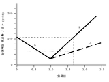
Figure 7 is a graph illustrating relative heat exchange and pressure differential as a function of eddy current ratio in accordance with various embodiments of the present invention.
본 발명의 이러한 특징 및 다른 특징은 본 발명의 다양한 실시예를 도시하는 첨부 도면과 함께 본 발명의 다양한 양태에 대한 이하의 상세한 설명으로부터 더 잘 이해할 수 있을 것이다. These and other features of the present invention will be better understood from the following detailed description of various aspects of the invention, together with the accompanying drawings, which illustrate various embodiments of the invention.
본 발명의 도면들은 일정한 비율로 도시된 것은 아니다. 도면들은 본 발명의 특정 양태만을 도시할 뿐, 본 발명의 범주를 제한하는 것이 아니다. 도면들에서, 유사한 도면 부호들은 도면들에서 유사한 구성요소들을 나타낸다. The drawings of the present invention are not necessarily drawn to scale. The drawings illustrate only certain aspects of the invention and are not intended to limit the scope of the invention. In the drawings, like reference numerals designate like elements in the figures.
도 1은 본 발명의 일 실시예에 따른 터빈(100)의 일부의 개략적인 단면도이다. 도 1에서, 로터(40)는 스테이터 부재(10)의 로터 보어(20) 내에 위치된다. 제1 휠스페이스(60)는 스테이터(10)의 종단부(facing end; 12)이 버킷(bucket; 50)의 제1 버킷 루트(70) 사이에 존재한다. 도 1에 가장 잘 도시된 바와 같이, 버킷(50)은 로터(50)에 고정되는 복수의 버킷(50, 52) 중 하나의 버킷이며, 터빈(100)과 같은 전형적인 터보기계와 같이 복수의 비회전 노즐(60, 62)과 교번된다. "블레이드(blade)"라는 용어는 항공 터빈에 대해 통상 사용되지만, "버킷(bucket)"이라는 용어는 육상 터빈을 위한 동일한 유형의 구성요소를 나타낼 때 사용된다는 것을 당업자들은 알 것이다. 그러나, 단순화를 위해 본 명세서에서 "버컷"이라는 용어는 버킷 또는 블레이드를 집합적으로 나타내는데 사용된다. 1 is a schematic cross-sectional view of a portion of a
복수의 시일(26, 28)이 스테이터(10)의 시일 공동(16, 18) 내에 각각 위치되며, 로터(40)를 스테이터(10)에 대해 밀봉시키는 기능을 한다. 도 1에 도시된 바와 같이, 제1 시일(26)은 브러시 시일(brush seal)이지만, 제2 시일(28)은 패킹 시일(packing seal)이다. 물론, 다른 시일 구성 및 조합체도 본 발명의 범주 내에서 가능하다. A plurality of
도 1의 실시예에서, 제1 통로(30)가 제1 시일(26)과 제2 시일(28) 사이의 제1 개구(32)로부터 제2 통로(38)와 스테이터(10)를 통해 스테이터(10)의 종단부(12) 상의 제2 개구(34)까지 연장된다. 이로 인해, 냉각 스팀이 제1 시일(26)과 제2 시일(28) 사이로부터 제1 휠스페이스(6)로 진행하여, 제1 버킷 루트(70)를 냉각시킬 수 있다. 이하에서 더 상세히 기술되는 바와 같이, 제2 통로(38)는 스테이터(10)의 종축에 대해 접선 방향으로(원주 방향으로) 경사져 있어서, 냉각 스팀이 소정의 각도로 제1 버킷 루트(70)에 접촉된다. 그러나, 제1 통로(30)도 선택에 따라 스테이터(10)의 종축에 대해 접선 방향으로 경사질 수도 있다. 통상, 그런 경사 각도는 로터(40)의 회전 방향이여서, 냉각 스팀의 와류비(swirl ratio) 및 수반되는 열 추출 효율이 증가될 것이다. 제2 통로(38)는 유동 배출 개구(34)의 가속화를 위해 수렴 또는 수렴-확대 섹션을 포함할 수도 있다. 1 the
도 1에 도시된 바와 같이, 선택적인 추가의 통로(90)가 제1 버킷 루트(70)에 제공될 수도 있어, 제1 휠스페이스(60) 내로 안내되는 냉각 스팀이 버킷 루트(70)를 통해 계속 유동하여 제1 버킷 루트(70)와 제2 버킷 루트(72) 사이의 제2 휠스페이스(61) 내로 유동할 수도 있다. 또한, 추가의 통로(90) 및/또는 제2 휠스페이스 (61) 내로의 추가의 통로의 개구(92)는 스테이터(10)의 종축에 대해 경사질 수도 있다. 예컨대, 그런 경사는 로터(40)의 회전 방향일 수도 있다. An optional
냉각 스팀을 제1 휠스페이스(60) 내로 도입하는 것, 특히 상당한 압력의 증가가 제1 휠스페이스(60) 내부에서 달성되는 경우의 추가적인 이점은 스팀 경로(66)로부터 제1 휠스페이스(60) 내로의 작동 고온 스팀의 누출이 감소되는 것인데, 작동 고온 스팀은 버킷 루트(70)를 가열하는 기능을 한다. A further advantage of introducing cooling steam into the
도 2는 본 발명의 다른 실시예에 따른 터빈(200)의 일부의 개략적인 단면도이다. 도 2에선, 인듀서 플레이트(inducer plate; 180)가 스테이터(110)의 종단부(112)에 부착되어 있다. 본 발명의 몇몇 실시예에 따르면, 인듀서 플레이트(180)는 종단부(112)에 비고정식으로 부탁되어 교체될 수 있다. 본 발명의 몇몇 실시예에 따르면, 제1 통로(130)와 제2 통로(138)는 각각의 제조를 위해 접선 방향으로 경사지지 않을 수도 있다. 이런 경우, 인듀서 통로(136)가 스테이터(110)의 종축에 대해 접선 방향으로 경사져, 냉각 스팀이 인듀서 플레이트(180)를 빠져나갈 때 마치 제1 통로(130) 및/또는 제2 통로(138)가 경사져 있는 것처럼 사실상 동일한 냉각 스팀의 경사를 제공할 수도 있다. 또한, 인듀서 통로(136)는 유동 배출 개구(134)의 가속화를 위해 수렴 또는 수렴-확대 섹션을 포함할 수도 있다. 2 is a schematic cross-sectional view of a portion of a
도 3 및 도 4는 각각 통로(182, 184, 186)이 접선 방향으로(원주 방향으로) 경사져 있는 인듀서 플레이트(180)의 일 실시예의 외면도 및 측면도이다. 단지 3개의 통로(182, 184, 186)가 도 3 및 도 4에 표시되고 도 4에 도시되어 있지만, 이는 단지 단순한 예시를 위한 것이다. 또한, 인듀서 플레이트(180)가 이용되는 상황의 요건에 따라 임의의 크기 또는 가변 크기를 갖는 임의의 개수의 통로가 이용될 수도 있다. Figures 3 and 4 are an exterior view and a side view, respectively, of one embodiment of the
도 3 및 도 4에 도시된 실시예에서, 인듀서 플레이트(180)는 제1 표면(182A) 및 제2 표면(182B)을 갖는 본체(182)와, 제1 표면(182A) 및 제2 표면(182B)을 통과하는 복수의 통로(184, 186, 188)를 포함한다. 제1 표면(182A) 또는 제2 표면(182B)은 스테이터(110)(도 2 참조)의 종단부(112)(도 2 참조)와 접촉된 상태로 배치되어, 통로(182, 184, 186)가 제2 통로(138)와 연통된다. 도 4에 도시된 바와 같이, 각각의 통로(184, 186, 188)는 스테이터(110)의 종축(A), 즉 제1 표면(182A) 및/또는 제2 표면(182B)에 사실상 수직인 라인에 대해 소정의 각도 α로 경사져 있다. 예컨대, 통로(186)에 대해 표면(182A) 상의 개구(185) 및 표면(182B) 상의 개구(187)가 표시되어 있다. 인듀서 플레이트(180)는 예컨대, 볼트, 나사 또는 다른 파스너, 용접 등을 포함하는 임의의 공지된 또는 추후 개발될 장치나 방법을 이용하여 종단부(112)에 부착될 수도 있다. 3 and 4, the
물론, 통로(184, 186, 188)가 스테이터(110)(도 2 참조)의 종축(A)에 대해 접선 방향으로 경사지는 각도 α는 이런 경사의 목표 효과에 따라 변경될 것이다. 그러나 통상적으로, 각도 α는 스테이터(110)의 종축(A)로부터 약 45° 내지 90°, 예컨대 약 60° 내지 약 85° 또는 약 80°이다. 상술된 바와 같이, 냉각 스팀의 원주 속도 나누기 로터의 속도로서 정의되는 냉각 스팀의 와류비가 효율적인 냉각을 제공하고 로터 수명을 연장시키는데 중요하다는 사실을 본 출원인이 발견하였다. 보다 구체적으로는, 약 1.7 이상의 와류비가 더 높은 열전달률을 야기한다는 사실을 본 출원인이 발견하였다. 스테이터(110)의 종축으로부터 약 45° 내지 90°의 각도가 그런 와류비를 달성하다는 것을 알아냈다. Of course, the angle alpha, in which the
도 5 및 도 6은 본 발명의 다른 실시예에 다른 터빈(300, 400)의 일부의 개략적인 단면도이다. 도 5에서, 제1 시일(226)은 도 1과 같은 브러시 시일이 아닌 패킹 링이다. 도 6에서, 선태적인 인듀서 플레이트(380)는 스테이터(310)의 종단부(312)에 부착되어 있다. 5 and 6 are schematic cross-sectional views of portions of
또한, 냉각 스팀이 제1 휠스페이스(60)(도 1 참조)로 이송되는 지점의 크기 및/또는 개수를 제한하는 것이 열전달을 향상시키며, 몇몇 경우에는 와류비도 증가시킨다는 사실을 본 출원인이 알아냈다. 예컨대, 통로(30)(도 1 참조)의 크기 및/또는 개수, 또는 제1 휠스페이스(60) 내로의 제2 개구(34)(도 1 참조)의 크기 및/또는 개수를 제한함으로써, 50 psid(제곱 인치당 파운드 차이) 이상의 압력차를 달성하여 냉각 스팀을 가속시키며, 열전달이 상당히 향상될 수 있다는 사실을 본 출원인이 알아냈다. 몇몇 경우에는, 열전달의 향상이 80% 정도이다. 몇몇 실시예에서, 압역차는 80 psid 이하이다. It has also been found by the applicant that restricting the size and / or number of points at which the cooling steam is transferred to the first wheel space 60 (see FIG. 1) improves heat transfer and, in some cases, increases vorticity . By limiting the size and / or number of passages 30 (see FIG. 1) or the size and / or number of the second openings 34 (see FIG. 1) into the
본 발명의 몇몇 실시예에서, 열전달의 향상은 유동을 가속시키기 위한 냉각 스팀의 압력차의 증가와 통로(184, 186, 188)의 경사의 조합을 통해 달성된다. 그러나, 본 발명의 다른 실시예에선 각도 α가 0°이거나 거의 0°라서, 통로(184, 186, 188)가 인듀서 플레이트(180)의 제1 표면(182A)과 제2 표면(182B)에 대해 사실상 평행하게 또는 완만한 각도로 배향되기 때문에, 열전달 향상이 냉각 스팀의 압력차의 증가에 의해 주로 달성될 수도 있다. 또 다른 실시예에선, 열전달 향상이 통로(184, 186, 188)의 경사에 의해 주로 달성되기 때문에, 냉각 스팀의 압력차에 있어서의 소정의 또는 상당한 증가가 없는데, 즉 압력차가 약 50 psid 미만이다. In some embodiments of the present invention, the enhancement of heat transfer is achieved through a combination of an increase in the pressure difference of the cooling steam to accelerate the flow and a gradient of the
도 7은 본 출원인의 관측 결과에 기초하는 본 발명의 다양한 실시예에 따른 상대적인 열교환 및 압력차를 와류비의 함수로서 도시하는 그래프이다. 도 7에서 알 수 있는 바와 같이, 상대적인 열교환은 와류비가 1.0을 향해 증가함에 따라 부분 A를 따라 초기에는 감소하는데, 와류비가 1.0인 지점에서 상대적인 열교환이 최소가 된다. 이는 1.0의 와류비에서 냉각 스팀의 속도가 로터의 속도와 동일해지기 때문으로 이해할 수 있는데, 즉 어떤 추가적인 열전달도 로터에 대한 냉각 스팀의 상대적인 이동을 통해 달성되지 않는 상태에서 로터가 기본적으로 냉각 스팀에 침지되기 때문으로 이해할 수 있다. 부분 A를 따르는 상대적인 열전달 값들은 본 발명의 다양한 실시예에 따른 경사진 통로(30, 38)(도 1 참조) 및/또는 인듀서 플레이트(180)(도 2 참조)를 이용하지 않는 냉각 스팀을 이용함으로써 달성될 수 있는 값들이다. FIG. 7 is a graph illustrating the relative heat exchange and pressure differential as a function of the eddy current ratio, in accordance with various embodiments of the present invention, based on the observations of Applicants. As can be seen in Figure 7, the relative heat exchange decreases initially along section A as the vortex ratio increases towards 1.0, where the relative heat exchange is minimized at a vortex ratio of 1.0. It can be understood that the velocity of the cooling steam at the vorticity ratio of 1.0 is equal to the speed of the rotor, that is to say that any additional heat transfer is not achieved through the relative movement of the cooling steam to the rotor, As shown in Fig. Relative heat transfer values along section A may be obtained by cooling steam that does not utilize
도 7을 여전히 참조하면, 와류비가 1.0을 넘어 증가함에 따라, 본 발명의 다양한 실시예에 따라 달성될 수 있는 바와 같이, 본 발명 없이, 즉 와류비가 1.0 이하인 경우에 달성될 수 있는 최대의 상대적인 열전달과 약 1.7의 와류비에서 동일해질 때까지 상대적은 열전달은 부분 B를 따라 증가한다. 약 1.7의 와류비는 1.0 이하의 와류비에 의해 달성될 수 있는 최대값보다 큰 상대적인 열전달을 야기한다. 도 7에서 알 수 있는 바와 같이, 약 2.5의 와류비에서 상대적인 열전달은 1.0 이하의 와류비에 의해 달성될 수 있는 최대값의 약 2배이다. Still referring to FIG. 7, as the eddy current ratio increases beyond 1.0, the maximum relative heat transfer that can be achieved without the present invention, i.e., the eddy current ratio of 1.0 or less, as can be achieved according to various embodiments of the present invention And vorticity ratios of about 1.7, the relative heat transfer increases along part B. The eddy current ratio of about 1.7 causes a relative heat transfer greater than the maximum value that can be achieved by the eddy current ratio of less than 1.0. As can be seen in FIG. 7, the relative heat transfer at a vorticity ratio of about 2.5 is about twice the maximum value that can be achieved by a vortex ratio of 1.0 or less.
도 7의 위치 C는 대응하는 와류비를 생성하는데 필요한 압력차를 나타낸다. 알 수 있는 바와 같이, 약 50 psid의 압력차가 약 1.7의 와류비를 달성하는데 필요하다. 이런 점에서, 압력차의 증가는 추가적인 와류비의 증가를 야기시켜, 더 높은 상대적인 열교환을 유발한다. 이는 상대적인 열교환이 위치 C에 도시된 압력차에 대응하는 성분뿐만 아니라, 본 발명의 다양한 실시예에 따른 경사진 통로 및/또는 인듀서 플레이트를 이용하여 달성되는 냉각 스팀의 경사에 대응하는 성분을 포함한다는 사실을 반영한다. 또한, 경사진 통로를 통해 냉각 유동을 진행시키고 바람직한 와류비를 달성하기 위한 필요 압력을 생성할 때의 도 1의 제1 시일(26)의 기능도 예증하고 있다. Position C in Fig. 7 represents the pressure differential required to produce the corresponding vorticity ratio. As can be seen, a pressure difference of about 50 psid is required to achieve a vortex ratio of about 1.7. In this regard, an increase in the pressure difference causes an increase in the additional vorticity ratio, leading to a higher relative heat exchange. This includes components corresponding to the slope of the cooling steam achieved using the inclined passageway and / or the inducer plate according to various embodiments of the present invention, as well as the components corresponding to the pressure differential shown in position C, relative heat exchange . It also illustrates the function of the
본 명세서에서 사용된 기술용어는 특정 실시예를 기술하기 위한 것일 뿐 본 발명을 제한하려는 것이 아니다. 본 명세서에 사용된 바와 같이, 단수형인 "하나" "상기"라는 용어는 본 명세서에 달리 명시되지 않는 한 복수형도 포함하는 것이다. 또한, 본 명세서에서 사용될 때 "포함하다" 및/또는 "포함하는"이라는 용어는 개시된 구성요소, 정수, 단계, 기능, 요소 및/또는 성분의 존재를 명시하지만, 하나 이상의 구성요소, 정수, 단계, 기능, 요소, 성분 및/또는 이들의 그룹의 존재 또는 추가를 배제하지 않는다. It is to be understood that the technical terminology used herein is for the purpose of describing particular embodiments only and is not intended to be limiting of the invention. As used herein, the singular forms "one" and "above " are intended to include the plural forms unless the context clearly dictates otherwise. Also, as used herein, the term " comprises "and / or" comprising " refers to the presence of stated elements, integers, steps, functions, elements and / , Function, element, component and / or group thereof.
본 명세서는 최상의 모드를 포함하는 본 발명을 기술하기 위해 그리고 임의의 장치나 시스템을 제조하여 이용하는 것과 임의의 통합되거나 관련된 방법을 수행하는 것을 포함하는 본 발명을 당업자들이 실시할 수 있게 하기 위해 예들을 이용하고 있다. 본 발명의 특허가능한 범주는 첨부된 특허청구범위에 의해 한정되며, 당업자가 실시할 수 있는 다른 예들을 포함할 수도 있다. 이런 다른 예들은 첨부된 특허청구범위의 문자 그대로의 표현과 다르지 않은 구조적인 요소를 포함하는 경우 또는 첨부된 특허청구범위의 문자 그대로의 표현과 사실상 다르지 않은 등가의 구조적인 요수를 포함하는 경우 첨부된 특허청구범위의 범주 내에 있는 것이다. This written description uses examples to describe the present invention including the best mode, and to enable those skilled in the art to practice the invention, including performing any integrated or related methods for making and using any device or system . The patentable scope of the invention is defined by the appended claims, and may include other examples that may be practiced by those skilled in the art. These other examples should not be construed as limiting the scope of the appended claims if they include structural elements that do not differ from the literal representation of the appended claims or if structural equivalents are not substantially different from the literal representations of the appended claims, And are within the scope of the claims.
100, 200, 300, 400 : 터빈
10 : 스테이터
12 : 종단부
16, 18 : 시일 공동
20 : 로터 보어
30, 130 : 제1 통로
32 : 제1 개구
34 : 제2 개구
38, 138 : 제2 통로
40 : 로터
50, 52 : 버킷
60, 62 : 비회전 노즐
60 : 제1 휠스페이스
61 : 제2 휠스페이스
66 : 스팀 경로
70 : 제1 버킷 루트
72 : 제2 버킷 루트
90 : 추가의 경로
92, 185, 187 : 개구
110, 310 : 스테이터
112, 312 : 종단부
134 : 유동 배출 개구
136 : 인듀서 경로
180, 380 : 인듀서 플레이스
182, 184, 186, 188 : 경로
182 : 본체
182A : 제1 표면
182B : 제2 표면
226 : 제1 시일 100, 200, 300, 400: turbine 10: stator
12: terminating
20: rotor bore 30, 130: first passage
32: first opening 34: second opening
38, 138: second passage 40: rotor
50, 52:
60: first wheel space 61: second wheel space
66: Steam path 70: First bucket root
72: Second Bucket Route 90: Additional Route
92, 185, 187:
112, 312: terminating end 134: flow outlet opening
136:
182, 184, 186, 188: path 182:
182A:
226: 1st seal
Claims (20)
제1 버킷 루트를 포함하는 로터와,
스테이터 부재를 포함하며,
상기 스테이터 부재가
상기 로터의 적어도 일부가 내부에 배치되는 로터 보어와,
상기 로터의 제1 버킷 루트에 인접하는 종단부와,
상기 로터에 대해 밀봉되도록 로터 보어 내부에 위치되고, 상기 종단부에 가장 인접한 제1 시일 및 제1 시일에 인접한 제2 시일을 포함하는 복수의 시일과,
상기 제1 시일과 제2 시일 사이의 지점에서 로터 보어의 표면으로부터 상기 종단부를 통해 각각 연장되는 복수의 통로를 포함하는 것인
터빈. As a turbine,
A rotor including a first bucket root,
A stator member,
The stator member
A rotor bore in which at least a portion of the rotor is disposed;
A terminating portion adjacent to the first bucket root of the rotor,
A plurality of seals positioned within the rotor bore to be sealed to the rotor and including a first seal closest to the end and a second seal adjacent the first seal,
And a plurality of passages extending from the surface of the rotor bore at the point between the first seal and the second seal, respectively, through the termination,
turbine.
긴 형상의 본체와,
상기 긴 형상의 본체의 내부에서 본체의 종축을 따르는 로터 보어와,
상기 로터 보어의 표면 상에 제1 개구를 가지며, 상기 긴 형상의 본체의 종단부 상의 제2 개구까지 상기 긴 형상의 본체를 통해 연장되는 적어도 하나의 통로와,
밀봉 장치를 포함하도록 로터 보어의 표면을 따르고, 상기 종단부와 적어도 하나의 통로의 제1 개구 사이에 배치되는 제1 리세스를 포함하며,
상기 종단부는 긴 현상의 본체의 종축에 대해 사실상 수직인 평면을 따라 위치되는 것인
스테이터 부재. A stator member for a turbine,
A long-shaped main body,
A rotor bore along the longitudinal axis of the body within the elongate body,
At least one passageway having a first opening on a surface of the rotor bore and extending through the elongate body to a second opening on the end of the elongate body,
A first recess along the surface of the rotor bore to include a sealing device and disposed between the termination and a first opening in the at least one passageway,
Said end being located along a plane which is substantially perpendicular to the longitudinal axis of the body of the long run
Stator member.
Applications Claiming Priority (2)
| Application Number | Priority Date | Filing Date | Title |
|---|---|---|---|
| US14/079,610 US9388698B2 (en) | 2013-11-13 | 2013-11-13 | Rotor cooling |
| US14/079,610 | 2013-11-13 |
Publications (1)
| Publication Number | Publication Date |
|---|---|
| KR20150055576A true KR20150055576A (en) | 2015-05-21 |
Family
ID=52991042
Family Applications (1)
| Application Number | Title | Priority Date | Filing Date |
|---|---|---|---|
| KR1020140155953A Abandoned KR20150055576A (en) | 2013-11-13 | 2014-11-11 | Rotor cooling |
Country Status (6)
| Country | Link |
|---|---|
| US (1) | US9388698B2 (en) |
| JP (1) | JP2015094359A (en) |
| KR (1) | KR20150055576A (en) |
| CN (1) | CN104632292A (en) |
| CH (1) | CH708868A2 (en) |
| DE (1) | DE102014115963A1 (en) |
Families Citing this family (5)
| Publication number | Priority date | Publication date | Assignee | Title |
|---|---|---|---|---|
| US10443422B2 (en) * | 2016-02-10 | 2019-10-15 | General Electric Company | Gas turbine engine with a rim seal between the rotor and stator |
| US10316681B2 (en) * | 2016-05-31 | 2019-06-11 | General Electric Company | System and method for domestic bleed circuit seals within a turbine |
| DE102016211280A1 (en) * | 2016-06-23 | 2017-12-28 | Siemens Aktiengesellschaft | steam turbine |
| RU181052U1 (en) * | 2018-02-19 | 2018-07-04 | Акционерное общество "Уральский турбинный завод" | Steam turbine flow compartment for mixing steam flows |
| CN117205778A (en) * | 2023-10-07 | 2023-12-12 | 张家口浣纱洗涤有限公司 | Homogenizer for detergent preparation |
Family Cites Families (13)
| Publication number | Priority date | Publication date | Assignee | Title |
|---|---|---|---|---|
| US3989410A (en) * | 1974-11-27 | 1976-11-02 | General Electric Company | Labyrinth seal system |
| US4822244A (en) * | 1987-10-15 | 1989-04-18 | United Technologies Corporation | Tobi |
| US5245821A (en) | 1991-10-21 | 1993-09-21 | General Electric Company | Stator to rotor flow inducer |
| US5555721A (en) * | 1994-09-28 | 1996-09-17 | General Electric Company | Gas turbine engine cooling supply circuit |
| CN1162345A (en) * | 1994-10-31 | 1997-10-15 | 西屋电气公司 | Gas turbine blades with cooled platforms |
| US6050079A (en) | 1997-12-24 | 2000-04-18 | General Electric Company | Modulated turbine cooling system |
| FR2831918B1 (en) * | 2001-11-08 | 2004-05-28 | Snecma Moteurs | STATOR FOR TURBOMACHINE |
| FR2840351B1 (en) * | 2002-05-30 | 2005-12-16 | Snecma Moteurs | COOLING THE FLASK BEFORE A HIGH PRESSURE TURBINE BY A DOUBLE INJECTOR SYSTEM BOTTOM BOTTOM |
| US6773225B2 (en) * | 2002-05-30 | 2004-08-10 | Mitsubishi Heavy Industries, Ltd. | Gas turbine and method of bleeding gas therefrom |
| US6945749B2 (en) * | 2003-09-12 | 2005-09-20 | Siemens Westinghouse Power Corporation | Turbine blade platform cooling system |
| US7331763B2 (en) * | 2005-12-20 | 2008-02-19 | General Electric Company | Turbine disk |
| US8381533B2 (en) * | 2009-04-30 | 2013-02-26 | Honeywell International Inc. | Direct transfer axial tangential onboard injector system (TOBI) with self-supporting seal plate |
| US8578720B2 (en) * | 2010-04-12 | 2013-11-12 | Siemens Energy, Inc. | Particle separator in a gas turbine engine |
-
2013
- 2013-11-13 US US14/079,610 patent/US9388698B2/en not_active Expired - Fee Related
-
2014
- 2014-11-03 DE DE201410115963 patent/DE102014115963A1/en not_active Withdrawn
- 2014-11-06 CH CH01721/14A patent/CH708868A2/en not_active Application Discontinuation
- 2014-11-07 JP JP2014226548A patent/JP2015094359A/en active Pending
- 2014-11-11 KR KR1020140155953A patent/KR20150055576A/en not_active Abandoned
- 2014-11-13 CN CN201410638884.3A patent/CN104632292A/en active Pending
Also Published As
| Publication number | Publication date |
|---|---|
| JP2015094359A (en) | 2015-05-18 |
| US20150132107A1 (en) | 2015-05-14 |
| CN104632292A (en) | 2015-05-20 |
| US9388698B2 (en) | 2016-07-12 |
| DE102014115963A1 (en) | 2015-05-13 |
| CH708868A2 (en) | 2015-05-15 |
Similar Documents
| Publication | Publication Date | Title |
|---|---|---|
| CN103206262B (en) | airfoil | |
| EP2615245B1 (en) | Film cooled turbine airfoil having trench segments on the exterior surface | |
| EP2679772B1 (en) | An airfoil | |
| US8784045B2 (en) | Seal assembly | |
| US11078797B2 (en) | Turbine bucket having outlet path in shroud | |
| US10584604B2 (en) | Group of blade rows | |
| US9885243B2 (en) | Turbine bucket having outlet path in shroud | |
| EP3047104B1 (en) | Turbomachine with endwall contouring | |
| EP2597263B1 (en) | Bucket assembly for turbine system | |
| US10316680B2 (en) | Turbine | |
| KR20150055576A (en) | Rotor cooling | |
| JP6742753B2 (en) | Turbine bucket platform for controlling intrusion loss | |
| EP2607629A1 (en) | Shrouded turbine blade with cooling air outlet port on the blade tip and corresponding manufacturing method | |
| EP3012409B1 (en) | Turbine assembly | |
| US8777564B2 (en) | Hybrid flow blade design | |
| US10774667B2 (en) | Steam turbine and methods of assembling the same | |
| CN103216276A (en) | Turbine packing deflector | |
| CN103206261B (en) | airfoil |
Legal Events
| Date | Code | Title | Description |
|---|---|---|---|
| PA0109 | Patent application |
St.27 status event code: A-0-1-A10-A12-nap-PA0109 |
|
| R17-X000 | Change to representative recorded |
St.27 status event code: A-3-3-R10-R17-oth-X000 |
|
| PG1501 | Laying open of application |
St.27 status event code: A-1-1-Q10-Q12-nap-PG1501 |
|
| A201 | Request for examination | ||
| A302 | Request for accelerated examination | ||
| PA0201 | Request for examination |
St.27 status event code: A-1-2-D10-D11-exm-PA0201 |
|
| PA0302 | Request for accelerated examination |
St.27 status event code: A-1-2-D10-D17-exm-PA0302 St.27 status event code: A-1-2-D10-D16-exm-PA0302 |
|
| D13-X000 | Search requested |
St.27 status event code: A-1-2-D10-D13-srh-X000 |
|
| D14-X000 | Search report completed |
St.27 status event code: A-1-2-D10-D14-srh-X000 |
|
| E902 | Notification of reason for refusal | ||
| PE0902 | Notice of grounds for rejection |
St.27 status event code: A-1-2-D10-D21-exm-PE0902 |
|
| T11-X000 | Administrative time limit extension requested |
St.27 status event code: U-3-3-T10-T11-oth-X000 |
|
| E13-X000 | Pre-grant limitation requested |
St.27 status event code: A-2-3-E10-E13-lim-X000 |
|
| P11-X000 | Amendment of application requested |
St.27 status event code: A-2-2-P10-P11-nap-X000 |
|
| P13-X000 | Application amended |
St.27 status event code: A-2-2-P10-P13-nap-X000 |
|
| E701 | Decision to grant or registration of patent right | ||
| PE0701 | Decision of registration |
St.27 status event code: A-1-2-D10-D22-exm-PE0701 |
|
| NORF | Unpaid initial registration fee | ||
| PC1904 | Unpaid initial registration fee |
St.27 status event code: A-2-2-U10-U13-oth-PC1904 St.27 status event code: N-2-6-B10-B12-nap-PC1904 |
|
| R18 | Changes to party contact information recorded |
Free format text: ST27 STATUS EVENT CODE: A-3-3-R10-R18-OTH-X000 (AS PROVIDED BY THE NATIONAL OFFICE) |
|
| R18-X000 | Changes to party contact information recorded |
St.27 status event code: A-3-3-R10-R18-oth-X000 |