CN102713579A - Appearance inspection device - Google Patents
Appearance inspection device Download PDFInfo
- Publication number
- CN102713579A CN102713579A CN2010800561966A CN201080056196A CN102713579A CN 102713579 A CN102713579 A CN 102713579A CN 2010800561966 A CN2010800561966 A CN 2010800561966A CN 201080056196 A CN201080056196 A CN 201080056196A CN 102713579 A CN102713579 A CN 102713579A
- Authority
- CN
- China
- Prior art keywords
- inspection
- image
- face
- inspection object
- slit light
- Prior art date
- Legal status (The legal status is an assumption and is not a legal conclusion. Google has not performed a legal analysis and makes no representation as to the accuracy of the status listed.)
- Granted
Links
Images




Classifications
-
- G—PHYSICS
- G01—MEASURING; TESTING
- G01N—INVESTIGATING OR ANALYSING MATERIALS BY DETERMINING THEIR CHEMICAL OR PHYSICAL PROPERTIES
- G01N21/00—Investigating or analysing materials by the use of optical means, i.e. using sub-millimetre waves, infrared, visible or ultraviolet light
- G01N21/84—Systems specially adapted for particular applications
- G01N21/88—Investigating the presence of flaws or contamination
- G01N21/95—Investigating the presence of flaws or contamination characterised by the material or shape of the object to be examined
- G01N21/9508—Capsules; Tablets
-
- G—PHYSICS
- G01—MEASURING; TESTING
- G01B—MEASURING LENGTH, THICKNESS OR SIMILAR LINEAR DIMENSIONS; MEASURING ANGLES; MEASURING AREAS; MEASURING IRREGULARITIES OF SURFACES OR CONTOURS
- G01B11/00—Measuring arrangements characterised by the use of optical techniques
- G01B11/30—Measuring arrangements characterised by the use of optical techniques for measuring roughness or irregularity of surfaces
- G01B11/303—Measuring arrangements characterised by the use of optical techniques for measuring roughness or irregularity of surfaces using photoelectric detection means
-
- G—PHYSICS
- G01—MEASURING; TESTING
- G01B—MEASURING LENGTH, THICKNESS OR SIMILAR LINEAR DIMENSIONS; MEASURING ANGLES; MEASURING AREAS; MEASURING IRREGULARITIES OF SURFACES OR CONTOURS
- G01B11/00—Measuring arrangements characterised by the use of optical techniques
- G01B11/30—Measuring arrangements characterised by the use of optical techniques for measuring roughness or irregularity of surfaces
- G01B11/306—Measuring arrangements characterised by the use of optical techniques for measuring roughness or irregularity of surfaces for measuring evenness
-
- G—PHYSICS
- G01—MEASURING; TESTING
- G01N—INVESTIGATING OR ANALYSING MATERIALS BY DETERMINING THEIR CHEMICAL OR PHYSICAL PROPERTIES
- G01N21/00—Investigating or analysing materials by the use of optical means, i.e. using sub-millimetre waves, infrared, visible or ultraviolet light
- G01N21/84—Systems specially adapted for particular applications
- G01N21/88—Investigating the presence of flaws or contamination
- G01N21/89—Investigating the presence of flaws or contamination in moving material, e.g. running paper or textiles
- G01N21/892—Investigating the presence of flaws or contamination in moving material, e.g. running paper or textiles characterised by the flaw, defect or object feature examined
Landscapes
- Physics & Mathematics (AREA)
- General Physics & Mathematics (AREA)
- General Health & Medical Sciences (AREA)
- Chemical & Material Sciences (AREA)
- Analytical Chemistry (AREA)
- Biochemistry (AREA)
- Life Sciences & Earth Sciences (AREA)
- Health & Medical Sciences (AREA)
- Immunology (AREA)
- Pathology (AREA)
- Investigating Materials By The Use Of Optical Means Adapted For Particular Applications (AREA)
- Engineering & Computer Science (AREA)
- Textile Engineering (AREA)
- Image Processing (AREA)
- Length Measuring Devices By Optical Means (AREA)
Abstract
Provided is an appearance inspection device capable of accurately inspecting the pattern of even an object having projections and recesses on the surface thereof. The appearance inspection device is provided with a surface shape inspection means and a surface pattern inspection means which are disposed near a transfer path for transferring an object to be inspected (K). The surface shape inspection means is provided with a slit light image capturing unit (21, 51) for capturing an image formed by applying band-shaped slit light to the object to be inspected (K), and a shape determination unit for determining the acceptance or nonacceptance of the surface shape on the basis of the captured image. The surface pattern inspection means is provided with a gray-scale image capturing unit (41, 71) for capturing a gray-scale image by applying diffusion light to the object to be inspected (K), and a pattern determination unit for determining the acceptance or nonacceptance of the surface pattern on the basis of the captured gray-scale image. The pattern determination unit receives, from the shape determination unit, information relating to a region in which at least a portion having projections and recesses of the surface of the object to be inspected (K) is present, sets the received region to a non-inspection region, and determines the acceptance or nonacceptance of the pattern.
Description
Technical field
The present invention relates to a kind of device, the outward appearance of inspection pharmaceuticals (tablet, capsule etc.), food, mechanical component or electronic component etc. (below, be called " inspection object ").
Background technology
In the past, as the device of the outward appearance on the said inspection object of inspection surface, known had that for example Japanese Patent Laid is opened clear 63-53452 communique (first precedent 1) or Japanese Patent Laid is opened disclosed device in the 2004-317126 communique (first precedent 2).
The testing fixture of this elder generation's precedent 1 is the surface irradiation diffused light to the inspection object; Utilize camera head suitably to take the surface; Gray level image through to gained is analyzed, and detects to be present in inspection lip-deep stains of object or Printing Department, differentiates whether it suitable.
This testing fixture is through to inspection object surface irradiation diffused light and from all directions illumination surface in heterogeneity; Thus, acquisition will be present in lip-deep concavo-convex taking-up, promptly suppress to produce by the concavo-convex shade that causes and make the surperficial emphasical gray level image of figure (stains or Printing Department).
On the other hand, the testing fixture of said first precedent 2 is to inspection object surface irradiation laser slit light, suitably takes the image of the laser slit light that is shone through camera head; According to optical cutting method, analyze the gained image, obtain the information of the relevant height on inspection object surface; And according to the gained elevation information; Detection is present in the lip-deep cut of checking object or damaged etc., and, calculate the volume of inspection object.
Patent documentation
Patent documentation 1: Japanese Patent Laid is opened clear 63-53452 communique
Patent documentation 2: Japanese Patent Laid is opened the 2004-317126 communique
Summary of the invention
[problem that invention will solve]
Yet, in the testing fixture of said first precedent, have the problem of following explanation in the testing fixture of first precedent 1.
Promptly; As stated; The testing fixture of elder generation's precedent 1 is that intention is through suppressing to be produced by the concavo-convex shade that causes that exists on the surface to inspection object surface irradiation stray light; Stress that the surface goes up the figure (stains or Printing Department) that exists, but when bigger concavo-convex, the mint-mark that the for example degree of depth is darker of existence was gone up on the surface, existence can't be eliminated the problem of its shade fully.
Under the situation of darker mint-mark, be difficult to and the inner face of surperficial equal extent ground illumination mint-mark, bottom especially, result; This bottom can produce shade, becomes dark gray level image thereby photograph this part, therefore; Although give suitable mint-mark, but still be judged to be defective products.
Especially under the situation of said pharmaceuticals, carry out mint-marks such as literal usually on its surface, but the device of said first precedent 1 can't be checked accurately to it.
On the other hand, because pharmaceuticals require highly assurance, so, if it is can carry out detections such as inspection of mint-mark portion or surface damage exactly, then very useful.
Whether suitable the present invention develops in view of above actual conditions, and its purpose is to provide a kind of appearance inspection device, even if the surface has dark concavo-convex article, also can check defectives such as this concavo-convex or surface blot exactly.
[technological means of dealing with problems]
For realizing said purpose, the present invention relates to a kind of appearance inspection device, it comprises:
Supply unit along specific transport path, is carried the inspection object;
The surface configuration inspection unit, inspection is by the surface configuration of the said inspection object of said supply unit conveying; And
The surfacial pattern of the said inspection object that surfacial pattern inspection unit, inspection are carried by said supply unit equally; And
Said surface configuration inspection unit comprises: slit light image image pickup part; Be provided near the said transport path; With the mode of banded slit light with the throughput direction quadrature of its irradiation route and said inspection object; Shine said inspection object surface, and the throughput direction from the shooting optical axis along said inspection object and the direction of intersecting with the optical axis of the slit light that shines said inspection object, shooting is shone the image of said slit light time to said inspection object; And shape decision portion, according to the image of being taken by this slit light image image pickup part, the shape facility on the said inspection object of identification surface judges whether this shape is suitable;
Said surfacial pattern inspection unit comprises: the gray level image image pickup part; Comparing said slit light image image pickup part is provided near the said transport path in upstream side or downstream; To the surface irradiation diffused light of said inspection object, take gray level image by the inspection object surface of this diffuse illumination; And the figure detection unit, according to the gray level image of being taken by this gray level image image pickup part, the graphic feature on the said inspection object of identification surface judges whether this figure is suitable;
And then; Said figure detection unit constitutes from the said shape decision portion's reception zone that have jog relevant information surperficial with said at least inspection object; The zone of receiving information is set at the non-inspection area of not carrying out checking, or muting sensitivity inspection area to check than the low sensitivity of inspection sensitivity in other zones, judges whether said figure is suitable.
According to appearance inspection device of the present invention, the inspection object of being carried by said supply unit is that its surface configuration is checked by said surface configuration inspection unit.That is, in said slit light image image pickup part, banded slit illumination is mapped to the surface of inspection object; Take its reflected light, in shape decision portion, according to said photographic images; Through for example optical cutting method, the data of the relevant 3D shape on calculating inspection object surface, and according to the data of calculating; The characteristic of identification surface configuration judges whether it is suitable.
On the other hand, the inspection object is that its surface is checked by said surfacial pattern inspection unit, and according to the gray level image of being taken by said gray level image image pickup part, the graphic feature that identification should the surface judges whether it is suitable.For example when having stains on the surface, stains are detected be figure, it is bad that its result is judged to be, and when printing literal etc. on the surface, this Printing Department detected is figure, judges whether printing state is suitable.
At this moment, the figure detection unit is from the said shape decision portion's reception zone that have jog relevant information surperficial with said at least inspection object, and the zone of receiving information is set at non-inspection area or muting sensitivity inspection area, judges whether figure is suitable.
When there is the mint-mark more concavo-convex, that the for example degree of depth is darker in the surface, even if through diffuse illumination illumination inspection surface in heterogeneity to a certain degree, also be difficult to the inner face of surperficial equal extent ground illumination mint-mark, especially bottom.
Therefore, this bottom can produce shade, and said gray level image image pickup part becomes shooting the gray level image of the lighter relatively dark portion of this part; Its result; If at the figure detection unit, even if carry out high sensitivity inspection, for example will differentiate whether to be the inspection threshold setting of stain etc. exist lighter relatively dark portion it to be judged to be the inspection of stain etc. and so in light side, so according to dark degree; Even if give suitable mint-mark, still can think it by mistake stain etc. and to be judged to be figure unusual.
Therefore; It is the shape decision portion from the said surface configuration inspection unit that can differentiate the surperficial shape of inspection object exactly that the present invention constitutes said figure detection unit; Receive and the relevant information in the zone that has jog of checking the object surface at least; The zone of receiving information is set at non-inspection area or muting sensitivity inspection area, judges whether the figure on inspection object surface is suitable.
That is,, thereby can accurately check the figure on inspection object surface if the non-inspection area that will exist the zone of jog to be made as not carry out the inspection relevant with figure then can prevent this jog erroneous judgement is decided to be stain etc.
On the other hand; To be made as the muting sensitivity inspection for the inspection in the zone that has jog; The inspection of this muting sensitivity is checking than the low sensitivity of inspection sensitivity in other zones, and whether for example will differentiate according to dark degree is that the inspection threshold setting of stain etc. is in dark side, if there is profound dark portion; Then be judged to be stain; Nonetheless, also can differentiate the dark portion that causes by jog, with the dark portion that causes by stain etc., thereby can accurately check the figure on inspection object surface.And, thus, when having profound stain etc. in this jog, can it be detected classification, compare with the situation that is made as non-inspection, can improve its inspection precision.
In the present invention; Said slit light image image pickup part and gray level image image pickup part all can be arranged on upstream side; But if consider the processing rapidity in the figure detection unit, then slit light image image pickup part is arranged on upstream side, the processing of shape decision portion is carried out prior to the processing of figure detection unit; Can not make in the processing of figure detection unit and produce stand-by time, therefore preferable.
And; The present invention preferably constitutes, and said slit light image image pickup part shines said slit light in vertical direction, and distinguishes photographic images from the throughput direction upstream side and the downstream both direction of said inspection object; Said shape decision portion will be synthetic by two images that said slit light image image pickup part is taken; And according to the image through synthesizing, the shape facility on the said inspection object of identification surface judges whether this shape is suitable.
When the shooting direction of said slit light image image pickup part when being unidirectional; This shooting direction is the locational surface at dead angle for being present in relatively; Can't obtain its image, thereby can't judge whether 3D shape is suitable this surface, but if take from relative both direction; Then can do one's utmost to reduce this dead angle, thereby can judge whether its 3D shape is suitable the surface is roughly whole.
[effect of invention]
As stated, according to the present invention,, also can check the figure that it is surperficial exactly even if the inspection object is to have concavo-convex article on the surface, especially have the article of deep seal.
Description of drawings
Fig. 1 is the front view of integral body of the appearance inspection device of an embodiment of the present invention.
Fig. 2 is the partial section of the arrow A-A direction of Fig. 1.
Fig. 3 is the key diagram that the summary of A face slit light image image pickup part and B face slit light image image pickup part constitutes.
Fig. 4 is the key diagram that the summary of A face gray level image image pickup part and B face gray level image image pickup part constitutes.
Fig. 5 is the block diagram of the formation of inspection classification processing portion.
Fig. 6 is the key diagram of irradiating state of the slit light of A face slit light image image pickup part and B face slit light image image pickup part.
Fig. 7 is the key diagram of the image taking mode of A face slit light image image pickup part and B face slit light image image pickup part.
Fig. 8 is the key diagram of the image taking mode of A face slit light image image pickup part and B face slit light image image pickup part.
Fig. 9 is the key diagram by the image of A face slit light image image pickup part and the shooting of B face slit light image image pickup part.
Figure 10 is the key diagram of the processing in A face brightness data conversion process portion and the B face brightness data conversion process portion.
Figure 11 is the key diagram of the processing in synthetic handling part of A face two images and the synthetic handling part of B face two images.
Figure 12 is the key diagram of the processing in A face Shape Feature Extraction handling part and the B face Shape Feature Extraction handling part.
Figure 13 is the key diagram of the processing in A face shape decision handling part and the B face shape decision handling part.
Figure 14 is the key diagram of the dead angle problem in A face slit light image image pickup part and the B face slit light image image pickup part.
Figure 15 is the front view of integral body of the appearance inspection device of other embodiments of the present invention.
Figure 16 is the block diagram of formation of the inspection classification processing portion of other embodiments of the present invention.
Figure 17 is the key diagram that the summary of the gray level image image pickup part of other embodiments of the present invention constitutes.
Figure 18 is the Shape Feature Extraction handling part of other embodiments of the present invention and the key diagram of the processing in the figure determination process section.
Figure 19 is the Shape Feature Extraction handling part of other embodiments of the present invention and the key diagram of the processing in the figure determination process section.
Figure 20 is the Shape Feature Extraction handling part of other embodiments of the present invention and the key diagram of the processing in the figure determination process section.
Embodiment
Below, according to accompanying drawing, preferred implementation of the present invention is described.
As shown in Figure 1, this routine appearance inspection device 1 comprises: supply unit 3, will check that object K supplies with arranging; The first straight line conveying portion 10 and the second straight line conveying portion 15, the inspection object K that straight line conveying is supplied with; A face slit light image image pickup part 21 and A face gray level image image pickup part 41 are provided near the transport path of the first straight line conveying portion 10; B face slit light image image pickup part 51 and B face gray level image image pickup part 71 are provided near the transport path of the second straight line conveying portion 15; Inspection classification processing portion 20; And division 90.
In addition, as the inspection object K in this example, can illustration pharmaceuticals (tablet, capsule etc.), food, mechanical component or electronic component etc., but do not receive any qualification of these illustrations.
Below, the details of said each one are described.
Said supply unit 3 comprises: hopper 4 can supply to throw in a large amount of inspection object K; Vibration charger 5 applies vibration to the inspection object K that discharges from the bottom of hopper 4 and makes it to advance; Chute 6 makes the inspection object K landing of discharging from the feeding terminal of vibration charger 5; Arrange platform 7, horizontally rotate, discharge the back that will be arranged in a row from the inspection object K that chute 6 is supplied with; And rotation delivery section 8, having the disc-shaped component that in vertical plane, rotates, the outer peripheral face that will be adsorbed on this disc-shaped component from the inspection object K that said arrangement platform 7 is discharged is carried; And said supply unit 3 is handed to the said first straight line conveying portion 10 after a large amount of inspection object K is arranged in a row successively.
The said first straight line conveying portion 10 and the second straight line conveying portion 15 have same configuration; And the state configuration that the second straight line conveying portion 15 reverses up and down with the relative first straight line conveying portion 10; The first straight line conveying portion 10 has transport path at an upper portion thereof, and the second straight line conveying portion 15 has transport path in its underpart.
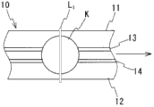
Fig. 2 is the partial section of arrow A-A direction among Fig. 1, and representes the structure of the first straight line conveying portion 10, the counterpart member of the symbolic representation second straight line conveying portion 15 of mark bracket.
Shown in Figure 2 like this, the first straight line conveying portion 10 comprises: side plate 11,12, dispose with specific interval mode in opposite directions; And endless round belt 13,14, by the guide groove guiding of the upper surface that is formed on this side plate 11,12, advance along this guide groove.By the separated space of side plate 11,12 folders is to be blocked by side plate 11,12 and other members (not shown) with the open mode in its top, and is maintained negative pressure by not shown vacuum pump.
So; Be maintained negative pressure through making in the said space; And produce the negative pressure suction force 13,14 of the round belts of advancing along guide groove; If inspection object K carry puts on this round belt 13,14, then because of said suction force by suction, be adsorbed on the round belt 13,14, and along with round belt 13,14 is advanced and carried towards this direct of travel.
Also situation is identical in the said second straight line conveying portion 15; Comprise side plate 16,17 and endless round belt 18,19; Be maintained negative pressure through pressing from both sides in the separated space by side plate 16,17; And produce the negative pressure suction force 18,19 of round belts, will check object K suction, be adsorbed on this round belt 18,19, and along with they are advanced and towards this direct of travel conveying.
The conveying top of the first straight line conveying portion 10 is to be connected with the feeding terminal of said rotation delivery section 8; The feeding terminal of the first straight line conveying portion 10 is to be connected with the conveying top of the second straight line conveying portion 15; The first straight line conveying portion 10 is from rotation delivery section 8 receiving check object K successively; And adsorbing the lower surface (B face) of checking object K and will check that object K is transported to feeding terminal, hand to the second straight line conveying portion 15.Likewise, the second straight line conveying portion 15 is from the first straight line conveying portion 10 receiving check object K successively, and the upper surface (A face) of absorption inspection object K will check that object K is transported to feeding terminal.
As shown in Figure 3, said A face slit light image image pickup part 21 comprises: video camera 22 is provided in above the transport path of the said first straight line conveying portion 10; Slit illumination love dart 23 shines banded slit light L1; Catoptron 24,25, under the said video camera 22 that will lead from the slit light L1 of this slit illumination love dart 23 irradiations to, make it to shine on the transport path of the first straight line conveying portion 10; Catoptron 26,27 receives the reflected light L2 that shines the slit light L1 on the transport path from throughput direction (arrow the is represented direction) upstream side of the first straight line conveying portion 10, and it is imported video camera 22; And catoptron 28,29, receive this reflected light L3 from conveyance direction downstream side, and it is imported video camera 22.
As shown in Figure 6, slit illumination love dart 23 and catoptron the 24, the 25th, the mode of throughput direction (arrow the is represented direction) quadrature of the inspection object K that said slit light L1 is carried by the first straight line conveying portion 10 with its irradiation route relatively is to the irradiation of vertical below.
And; As shown in Figure 7; Video camera 22 is reflected light L2 of this slit light L1 when receiving the inspection object K illumination slit light L1 that carried by the first straight line conveying portion 10 of throughput direction (arrow the is represented direction) upstream side from inspection object K; Receive reflected light L3 from the downstream, and acquisition image separately.If from said both direction visual inspection, then become Fig. 8 (a) and (b) shown in situation, but the image of the irradiation route of the slit light L1 that video camera 22 acquisitions get from this both direction observation post.In addition, Fig. 7 is the style of shooting with video camera 22 in easy understanding and the simple equivalents presentation graphs 3.
An example to taking the image of a reflected light (for example, reflected light L2) is shown in Fig. 9.As shown in the figure; If will be made as X with the direction of said throughput direction quadrature; Throughput direction is made as Y, and so, the image of shooting becomes the state (also with reference to Fig. 8) of the partial L s corresponding with inspection object K surface from being shifted to the Y direction with the corresponding partial L b of basal plane.
This is as shown in Figure 7ly to cause because of the direction of illumination of taking direction and slit light intersects; And be called so-called optical cutting method; The pixel (Xi, Yi) of just corresponding image Ls for example with inspection object K surface; The inspection object K corresponding with this pixel (Xi) surface can foundation and the difference of the pixel (Yi) of the pixel (Yj) of the corresponding image Lb of basal plane and image Ls at a distance of the height of said basal plane, calculates through the geometry computing method.In this example, direct calculating inspection object K surface height, but comprising elevation information in the image by video camera 22 shootings based on this optical cutting method.
Then, shot image data like this is sent to inspection classification processing portion 20 from video camera 22.At this moment; Video camera 22 is not to send both full-pixel position (Xi, Yi) (i=0~n) set up related all images data with its brightness data; But as shown in Figure 9, will contain directions X location of pixels (Xi), and these row in have a high-high brightness the position data (Xi, Yi) of location of pixels (Yi) as image data transmission to inspection classification processing portion 20.Through this processing, send data volume and tail off, the processing speed of its transmission speed or inspection classification processing portion 20 can be improved, thereby fast processing can be carried out.
And; Video camera 22 is the images that capture said both direction with specific shutter speed; To the said view data of major general during to the upper surface irradiating laser of inspection object K, the two field picture of gained sends to said inspection classification processing portion 20 during as each shutter.
In this way, this A face slit light image image pickup part 21 is taken the image of the elevation information that comprises inspection object K upper surface (A face), and this image is sent to said inspection classification processing portion 20.
Said B face slit light image image pickup part 51 comprises video camera 52, slit illumination love dart 53 and the catoptron 54,55,56,57,58,59 with said A face slit light image image pickup part 21 identical formations, and with the state that reverses up and down with said A face slit light image image pickup part 21 be provided in the said second straight line conveying portion 15 near.In addition, among Fig. 3, the counterpart member of the symbolic representation B face slit light image image pickup part 51 of mark bracket.
In this way; This B face slit light image image pickup part 51 in the same way; Video camera 52 receives the reflected light to the slit light L1 of lower surface (B face) irradiation of the inspection object K that carried by the second straight line conveying portion 15 from the throughput direction upstream side of inspection object K and downstream both direction; Generating should this catoptrical said view data (comprise directions X location of pixels (Xi), and in these row, have the position data (Xi, Yi) of the location of pixels (Yi) of high-high brightness), send to said inspection classification processing portion 20 as two field picture to the said view data of major general during to the lower surface irradiating laser of checking object K.
Said A face gray level image image pickup part 41 is to compare said A face slit light image image pickup part 21 to be provided in conveyance direction downstream side; And it is as shown in Figure 4; Comprise: hemisphere shelly pervasion component 44; With transport path that covers the said first straight line conveying portion 10 and the mode that said inspection object K is passed through, be provided in the transport path top of the said first straight line conveying portion 10; A plurality of lamps 43 are provided in the outside of pervasion component 44, towards the internal irradiation light of pervasion component 44; And video camera 42, be arranged on pervasion component 44 tops, through being arranged on the peristome 44a at pervasion component 44 tops, take in this pervasion component 44.
Light diffusion when seeing through pervasion component 44 by lamp 43 irradiations becomes non-direction scattered light (diffused light), to throwing light in the space that is covered by pervasion component 44.The inspection object K that is moved in the pervasion component 44 by the first straight line conveying portion 10 is thrown light on its upper surface (A face) by this diffused light in heterogeneity.And because the upper surface (A face) that throws light in heterogeneity in this way, so concavo-convex even if upper surface (A face) exists, its whole face is also thrown light on equably, makes this upper surface become the state that its gray scale obtains stressing.
Said video camera 42 comprises line sensor or area sensor; And take the gray level image of moving into the upper surface (A face) of the inspection object K in the pervasion component 44 by the first straight line conveying portion 10 with specific shutter speed; With the image in the whole zone of upper surface at least (A face) of gained, the two field picture of taking during as each shutter sends to said inspection classification processing portion 20.
Like this; This A face gray level image image pickup part 41; Take by diffused light through said video camera 42 and to throw light in heterogeneity and the inspection object K upper surface (A face) of the state that gray scale obtains further stressing, and the gray level image of taking is sent to said inspection classification processing portion 20.
Said B face gray level image image pickup part 71 is to compare said B face slit light image image pickup part 51 to be provided in conveyance direction downstream side; And comprise pervasion component 74, a plurality of lamp 73 and video camera 72 with said A face gray level image image pickup part 41 identical formations, and with the state that reverses up and down with A face gray level image image pickup part 41 be provided in the said second straight line conveying portion 15 near.In addition, among Fig. 4, the counterpart member of the symbolic representation B face gray level image image pickup part 71 of mark bracket.
Like this; In this B face gray level image image pickup part 71 similarly; The diffused light that produces through effect to throw light on the in heterogeneity lower surface (B face) of the inspection object K that carries by the second straight line conveying portion 15 because of lamp 73 and pervasion component 74; And utilize the peristome 74a of video camera 72 through pervasion component 74; Shooting makes the said lower surface (B face) of the state that gray scale further stresses because of the illumination of this homogeneous, and the two field picture taken during as shutter at every turn of the image in the whole zone of the lower surface at least that will take (B face), sends to said inspection classification processing portion 20.
As shown in Figure 5, said inspection classification processing portion 20 comprises A face shape decision portion 30, A face figure detection unit 45, B face shape decision portion 60, B face figure detection unit 75 and classification control part 91.
Shown in Figure 5 like this, said A face shape decision portion 30 comprises A face slit light image storage part 31, A face brightness data conversion process portion 32, A face two images synthetic handling part 33, A face Shape Feature Extraction portion 34 and A face shape decision handling part 35.
A face slit light image storage part 31 is stored respectively from the view data (two field picture) of the both direction of said A face slit light image image pickup part 21 receptions.
A face brightness data conversion process portion 32 reads the two field picture of the both direction that is stored in A face slit light image storage part 31 respectively; Carry out following processing; Convert the position data that comes from the height composition to corresponding the brightness data of should height composition setting, generate the new image data that composition highly shows with brightness data.
Particularly; A face brightness data conversion process portion 32 reads the frame image data of a side at first successively; According to its location of pixels (Xi, Yi), shown in figure 10, the location of pixels (Yi) that will belong to the height composition converts the brightness data of 256 GTGs to; Generation comprises the view data of location of pixels (Xi) and brightness data; Successively all two field pictures are changed, generate new image data (comprise two dimensional surface position data, with each position of expression in the view data of brightness data of elevation information, below be called " luminance picture data ").Then, the view data to opposite side also generates the luminance picture data in the same way.
The synthetic handling part 33 of said A face two images will be by said A face brightness data conversion process portion's 32 data-switching the luminance picture data of newly-generated both direction synthesize luminance picture data.Can know according to Fig. 7; When taking inspection object K from the oblique upper of throughput direction upstream side; The reflected light of the front portion of inspection object K a little less than, when when the oblique upper of conveyance direction downstream side is taken, the reflected light at the rear portion of inspection object K dies down; Therefore, the view data about these parts becomes inaccurate.
Expression is taken image that the image transitions that obtain form with the inspection object K of Fig. 7 from its throughput direction upstream side through said A face brightness data conversion process portion 32 among Figure 11 (a), the converted image of the image that same expression is taken from conveyance direction downstream side among Figure 11 (b).Among Figure 11 (a), the top of image (by the part of white line encirclement) becomes inaccurate, and among Figure 11 (b), the bottom of image (by the part of white line encirclement) becomes inaccurate.Therefore; These two images are synthetic, for example under the situation that data lack each other, distribute the data of existence side; Exist each other under the data conditions; Distribute its mean value, thus, can obtain whole the image that accurately shows of the upper surface that will check object K (A face) shown in Figure 11 (c).
In addition; According to the shape on inspection object K surface, and only from unidirectional shooting, for becoming the position of taking the direction dead angle; Can't receive the reflected light of said laser L1 fully; But can pass through to take from both direction, and take this dead angle part from other directions, this also means the meaning that existence is taken from both direction.
For example, shown in figure 14, when there is notch part 100 in the surface of inspection object K; If video camera 22 is taken from the direction of being represented by solid line; Can produce the 100a of dead angle portion so, if but take from its reverse direction (direction of representing by dot-and-dash line), damned bight 100a then can be taken.
Said A face Shape Feature Extraction portion 34 is the composographs that generate according to by the synthetic handling part 33 of said A face two images, the processing of extracting shape facility.Particularly, through so-called smoothing filter composograph is carried out smoothing and handle, generate the character image data of the difference of the smoothing view data of getting gained and said composograph data.
Composograph is the image that the height composition is converted to the brightness data gained; Brightness representes to check the height of the upper surface (A face) of object K, but can be through from composograph, deducting the image of the big part of variable quantity that the equalization image obtains to stress the short transverse of upper surface (A face).For example; Shown in figure 12; Through from composograph (Figure 12 (a)), deducting smoothing image (Figure 12 (b)), and shown in Figure 12 (c), with the circumferential profile of inspection object K, stress as dark portion in the numeral " 678 " of upper surface (A face) with stamp.The character image data that said A face Shape Feature Extraction portion 34 will generate in this way sends to A face shape decision handling part 35.
And 34 pairs of character image datas that generated of A face Shape Feature Extraction portion are analyzed, and have the zone of jog in this image of identification, and the information relevant with the zone of identification is sent to following A face figure determination process section 50.
Whether said A face shape decision handling part 35 is the correlated characteristic images according to the surface configuration that is generated by said A face Shape Feature Extraction portion 34, and its related data with suitable surface configuration is compared, differentiate to stamp suitable or its quality such as N/D is arranged.
Said A face figure detection unit 45 comprises A face gray level image storage part 46, and storage is from the gray level image of the said A face of said A face gray level image image pickup part 41 receptions; A face gray level image binary conversion treatment portion 47 carries out binary conversion treatment with specific reference value to the A face gray level image that is stored in this A face gray level image storage part 46; A extracts handling part 48 in the face of the portion of elephant, from through the image of binary conversion treatment, extracting the image section of the upper surface (A face) that belongs to inspection object K; A face graphic feature extracts handling part 49, and the part of the black in the image that extracts (visuals) is extracted; And A face figure determination process section 50, the black part (visuals) and the specific reference pattern that extract are compared, judge its quality.
The gray level image of taking and be stored in said A face gray level image storage part 46 by said A face gray level image image pickup part 41 is a multivalue image; And this multivalue image is carried out binary conversion treatment with specific reference value; Then; Through the image of binary conversion treatment, extract the image section of the upper surface (A face) that belongs to inspection object K from this, and then, the part of the black in the image that extracts (visuals) is extracted; Black part (visuals) and specific reference pattern are compared, differentiate its quality.
For example when the upper surface (A face) of suitable inspection object K during with any printing word figures; If there is the black part of extracting; Then it being differentiated is that stain is bad; When the surface has the printing word figures, the black part (visuals) and the suitable figure that extract are compared, differentiate quality according to its goodness of fit.
At this moment; The information that A face figure determination process section 50 receives about the zone that has said jog from said A face Shape Feature Extraction handling part 34; The zone that belongs to the zone that has said jog in the characteristic image that will be generated by said A face graphic feature extraction portion 49 is set at non-inspection area, carries out saidly good and badly judging.
When there is the mint-mark more concavo-convex, that the for example degree of depth is darker in the surface of inspection object K; Should check object K surface even if can throw light in heterogeneity to a certain extent through the diffused illumination of using said lamp 43 and pervasion component 44; Also be difficult to and the inner face of surperficial equal extent ground illumination mint-mark, bottom especially; Therefore, this bottom can produce shade, and will photograph the gray level image that this part becomes dark color by said A face gray level image image pickup part 41.
Therefore, the processing of extracting handling part 48 in the face of the portion of elephant via said A face gray level image binary conversion treatment portion 47, A is extracted in the image that handling part 49 generates by A face graphic feature and to be generated the image that this bottom becomes black.Expression is extracted the image that handling part 49 generates by said A face graphic feature among Figure 13 (a) when having digital mint-mark " 678 " on the inspection object K surface.In addition, the circle in the image is black is existing stain on the inspection object K surface.
Therefore; When there is this mint-mark in the surface of inspection object K; If directly use by A face graphic feature and extract the view data that handling part 49 generates, carry out that its surfacial pattern is good and bad to be judged, what for unusual to checking normally originally that object K also is judged to be figure.
Therefore; This is the above information that receives about the zone that has jog from A face Shape Feature Extraction handling part 34 for example; The zone that belongs to the zone that has said jog in the correlated characteristic image of the surfacial pattern that will be generated by said A face graphic feature extraction portion 49 is set at non-inspection area, carries out the quality of its figure and judges.
For example when the characteristic image that is extracted handling part 49 generations by A face graphic feature becomes shown in Figure 13 (a); If the correlated characteristic image of the surface configuration that is generated by A face Shape Feature Extraction handling part 34 is the image shown in Figure 13 (b); A face figure determination process section 50 is shown in Figure 13 (c) so; The zone of the existence of mint-mark portion numeral " 678 " is set at non-inspection area; And shown in Figure 13 (d), only will justify blackboard and judge that as the inspection object its quality, this example are that circle blackboard branch is judged to be stain is bad.
So, can be set at non-inspection area, and accurately check whether the figure on inspection object K surface is suitable through existing jog on the surface that will check object K in this way.
As shown in Figure 5, said B face shape decision portion 60 comprises B face slit light image storage part 61, B face brightness data conversion process portion 62, B face two images synthetic handling part 63, B face Shape Feature Extraction handling part 64 and B face shape decision handling part 65.And; B face slit light image storage part 61 has identical formation with said A face slit light image storage part 31; B face brightness data conversion process portion 62 has identical formation with said A face brightness data conversion process portion 32; The synthetic handling part 63 of B face two images has identical formation with the synthetic handling part 33 of said A face two images; B face Shape Feature Extraction handling part 64 has identical formation with said A face Shape Feature Extraction handling part 34, and B face shape decision handling part 65 has identical formation with said A face shape decision handling part 35, and carries out same treatment.In this way, the correlated characteristic of the shape of the lower surface (B face) of checking object K detects in B face shape decision portion 60, and differentiates its quality.
Shown in Figure 5 like this, said B face figure detection unit 75 comprises B face gray level image storage part 76, B face gray level image binary conversion treatment portion 77, B in the face of the portion of elephant extracts handling part 78, B face graphic feature extracts handling part 79 and B face figure determination process section 80.B face gray level image storage part 76 has identical formation with said A face gray level image storage part 46; B face gray level image binary conversion treatment portion 77 has identical formation with said A face gray level image binary conversion treatment portion 47; B has identical formation with said A in the face of the portion of elephant extracts handling part 48 in the face of the portion of elephant extracts handling part 78; B face graphic feature extracts handling part 79 and has identical formation with said A face graphic feature extraction handling part 49; B face figure determination process section 80 has identical formation with said A face figure determination process section 50, and carries out same treatment.In this way, this B face figure detection unit 75 detects the correlated characteristic of the figure of the lower surface (B face) of checking object K, and differentiates its quality.
Said classification control part 91 is from said A face shape decision handling part 35, A face figure determination process section 50, B face shape decision handling part 65 and B face figure determination process section 80, to receive result of determination respectively; And, then category signal is sent to this division 90 being judged as in the time that this bad inspection object K arrives said division 90 if any handling part at least among these handling parts receives bad result of determination.Said division 90 is recovered to defective products with qualified inspection object K and reclaims the chamber when receiving this category signal, the inspection object K that when not receiving category signal, then will carry is recovered to non-defective unit and reclaims the chamber.
Like above detailed elaboration; According to this routine appearance inspection device 1, during carrying, according to the image of taking by A face slit light image image pickup part 21 by the first straight line conveying portion 10; In A face shape decision portion 30 to the shape of the upper surface (A face) of inspection object K suitable inspection the whether; And according to the image of being taken by A face gray level image image pickup part 41, whether the figure of this upper surface of inspection (A face) is suitable in A face figure detection unit 45, then; During carrying by the second straight line conveying portion 15; According to the image of taking by B face slit light image image pickup part 51, in B face shape decision portion 60 to the shape of the lower surface (B face) of inspection object K suitable inspection the whether, and according to the image of taking by B face gray level image image pickup part 71; Whether inspection this lower surface (B face) diagram shape is suitable in B face figure detection unit 75, automatically the shape and the figure of the upper and lower surface of inspection object K checked.
And; A face figure detection unit 45 and B face figure detection unit 75 are at the correlated characteristic that extracts said figure; Judge when figure is whether suitable that from the information that A face shape decision portion 30 and B face shape decision portion 60 receive respectively about the zone that has jog, the zone that will belong to the zone that has said jog is set at non-inspection area; Carrying out the quality of its figure judges; Therefore, even if when having jog such as mint-mark on the table back of the body surface of inspection object K, also can check the figure of this upper and lower surfaces exactly.
And; A face slit light image image pickup part 21 and B face slit light image image pickup part 51 are from the throughput direction upstream side of inspection object K and the both direction photographic images in downstream; And A face shape decision portion 30 and B face shape decision portion 60 are synthetic with two images of gained, generate an image, according to the composograph that generates; Whether the shape of differentiating inspection object K upper and lower surfaces is suitable; Therefore, the image at dead angle can be obtained not have as possible, thereby the shape of whole of said upper and lower surfaces can be checked exactly.
In addition, this example is to make A face slit light image image pickup part 21 compare A face gray level image image pickup part 41 to be arranged on upstream side, therefore, in A face slit light image storage part 31, stores the data that are equivalent to same inspection object K prior to A face gray level image storage part 46.Therefore; Make the processing execution of the processing of the A face brightness data conversion process 32~A of portion face shape decision handling part 35 prior to the A face gray level image binary conversion treatment 47~A of portion face figure determination process section 50; A face figure determination process section 50 can be with reference to handling and can not produce the stand-by period from the data of A face Shape Feature Extraction handling part 34, thereby can carry out fast processing.
Likewise; In B face slit light image storage part 61, store the data that are equivalent to same inspection object K prior to B face gray level image storage part 76; B face figure determination process section 80 can be with reference to handling and can not produce the stand-by period from the data of B face Shape Feature Extraction handling part 64, thereby can carry out fast processing.
Yet; Need not under the situation of this fast processing; Can be in A face slit light image storage part 31 and A face gray level image storage part 46 after storage is equivalent to the data of same inspection object K respectively; The processing of the executed in parallel A face brightness data conversion process 32~A of portion face shape decision handling part 35 side by side, with the processing of the A face gray level image binary conversion treatment 47~A of portion face figure determination process section 50; And; Also can be in B face slit light image storage part 61 and B face gray level image storage part 76 after storage is equivalent to the data of same inspection object K respectively, the processing of the executed in parallel B face brightness data conversion process 62~B of portion face shape decision handling part 65 side by side, with the processing of the B face gray level image binary conversion treatment 77~B of portion face figure determination process section 80.
In the case, also can A face gray level image image pickup part 41 be compared A face slit light image image pickup part 21 and be provided in upstream side, B face gray level image image pickup part 71 compared B face slit light image image pickup part 51 be provided in upstream side.
More than an embodiment of the present invention is illustrated, but the concrete mode that the present invention can take does not receive its any qualification, can in the scope that does not break away from spirit of the present invention, take other modes.
For example, in the present invention, the meaning on the surface of the conduct inspection object face of inspection object K is not limited to upper surface shown in the example (A face) and lower surface (B face), and expression comprises surperficial whole of its outer peripheral face (side).
Below; According to Figure 15 to Figure 20; Appearance inspection device 100 is described, this appearance inspection device 100 constitute the upper surface that can check object K shape inspection and figure inspection, with the figure inspection of the side of on the throughput direction of inspection object K, observing from the left and right sides.
Shown in figure 15, this appearance inspection device 100 comprises: have and the supply unit of the identical formation of last example 3, the first straight line conveying portion 10, A face slit light image image pickup part 21 and division 90; Gray level image image pickup part 130 is provided in the downstream of A face slit light image image pickup part 21; And inspection classification processing portion 110, receive view data from A face slit light image image pickup part 21 and gray level image image pickup part 130, check classification processing.
In addition, division 90 is arranged on the conveying downstream end of the first straight line conveying portion 10, according to the instruction from said inspection classification processing portion 110, will be categorized as non-defective unit and defective products by the inspection object K that the first straight line conveying portion 10 carries.
Shown in figure 17, said gray level image image pickup part 130 possesses the formation that newly is provided with video camera 131,132 at the A face gray level image image pickup part 41 of last example.Video camera 131 is that the throughput direction towards inspection object K is that paper is provided in the left side, and the peristome 44b of the left side through being arranged on pervasion component 44 takes the gray level image of the left surface of the inspection object K that is positioned at this pervasion component 44.On the other hand, video camera 132 is to be provided in the right side towards paper, and the peristome 44c of the right side through being arranged on pervasion component 44 takes the gray level image of the right flank of the inspection object K that is positioned at this pervasion component 44.
The gray level image of the left surface of the inspection object K that takes with the gray level image of the upper surface (A face) of the inspection object K that takes by video camera 42 in this way, by video camera 131, and the gray level image of the right flank of the inspection object K that takes by video camera 132 send to said inspection classification processing portion 110 respectively.
Shown in figure 16, said inspection classification processing portion 110 comprises A face shape decision portion 30, A face figure detection unit 45 and the classification control part 91 of example; And newly-installed in addition left surface figure detection unit 111 and right flank figure detection unit 120.
Said left surface figure detection unit 111 comprises left surface gray level image storage part 112, left surface gray level image binary conversion treatment portion 113, left surface object portion extraction handling part 114, left surface graphic feature extraction handling part 115 and left surface figure determination process section 116; Likewise, said right flank figure detection unit 120 comprises right flank gray level image storage part 121, right flank gray level image binary conversion treatment portion 122, right flank object portion extraction handling part 123, right flank figure feature extraction handling part 124 and right flank figure determination process section 125.
These left surface gray level image storage parts 112 and right flank gray level image storage part 121 are the function portions that carry out same treatment with said A face gray level image storage part 46; Left surface gray level image binary conversion treatment portion 113 and right flank gray level image binary conversion treatment portion 122 are the function portions that carry out same treatment with said A face gray level image binary conversion treatment portion 47; Left surface object portion extracts handling part 114 and right flank object portion extraction handling part 123 is to extract the function portion that handling part 48 carries out same treatment with A in the face of the portion of elephant, and the left surface graphic feature extracts handling part 115 and right flank figure feature extraction handling part 124 is to extract the function portion that handling part 49 carries out same treatment with said A face graphic feature.Therefore, omit its detailed description here.
The A face Shape Feature Extraction handling part 34 of this mode not only carries out existing in this image of analytical characteristic view data and identification the upward routine of zone of jog to handle; And when analysis result judges that the jog that is present in the A face also relates to left surface and/or right flank; In the image of left surface of taking in this way and/or right flank; There is the zone of said jog in calculating, and will send to said left surface figure determination process section 116 and/or right flank figure determination process section 125 with the relevant information of calculating in zone.
For example, when shown in figure 18, when upper surface (A face) stamp of inspection object K has the secant G of similar its outer peripheral face opening; The image of the left surface of taking from arrow C direction by video camera 131; Shown in figure 19, there is the possibility that becomes dark portion with the corresponding part of this secant G, likewise; The image of the right flank of taking from arrow D direction by video camera 132, also exist and manifest the possibility of the dark portion corresponding shown in Figure 20 with secant G.
Therefore; A face Shape Feature Extraction handling part 34 analytical characteristic view data; For example shown in Figure 180; Throughput direction leading section with inspection object K is a benchmark, calculates the position (la1 and la2) and the degree of depth ha thereof of being presented in the secant G in the left surface image, and calculates the position (lb1 and lb2) and the degree of depth hb thereof of being presented in the secant G in the right hand view picture; The relevant information (la1, la2, ha) of left surface is sent to left surface figure determination process section 116, and the relevant information (lb1, lb2, hb) of right flank is sent to right flank figure determination process section 125.
Then; Left surface figure determination process section 116 is when receiving said information; Shown in figure 19, with the zone that has this secant G, promptly upper surface and the dot-and-dash line area surrounded by inspection object K is set at non-inspection area, as above routinely said figure is carried out the quality judgement.
Likewise, right flank figure determination process section 125 is when receiving said information, and is shown in figure 20, with the zone that has this secant G, promptly upper surface and the dot-and-dash line area surrounded by inspection object K is set at non-inspection area, and figure is carried out the quality judgement.
So; If the bad result of determination of any handling part output from A face shape decision handling part 35, A face figure determination process section 50, left surface figure determination process section 116 and right flank figure determination process section 125; Then send category signal, will be judged to be bad inspection object K through said division 90 and be recovered to defective products recovery chamber from classification control part 91.
So; Appearance inspection device 100 according to this embodiment; When the upper surface that is present in inspection object K concavo-convex also related to the side, the information that will obtain according to the shape check result of upper surface was used for the figure inspection of side, thus; The misinterpretation that causes because of this is concavo-convex in the figure inspection can be prevented, thereby the inspection precision of this side can be improved.
In addition, beyond any doubt, with said appearance inspection device 1 likewise, in the appearance inspection device 100 of this embodiment, also can constitute the lower surface of inspection object K is checked.
And said two routine modes are that the zone that has jog is set at non-inspection area, check the figure inspection in the classification processing portion 20,110, but do not receive this any qualification.
For example; Also can in inspection classification processing portion 20,110, delete this each gray level image binary conversion treatment portion 47,77,113,122; And directly handle with multivalue image; And the zone that there is jog in each 49,79,115,124 pairs of handling part of graphic feature extraction is to check than other regional low sensitivity of inspection sensitivity; For example implement will according to dark degree differentiate whether be the inspection threshold setting of stain etc. in dark side, if there is profound dark portion, then be judged to be the muting sensitivity inspection of stain and so on.
Thus, when there is profound stain etc. in this jog, can detects classification to it, and compare, can improve its inspection precision with the situation that is made as non-inspection.
And in the inspection of said figure, there is the unintelligible person that becomes in the bight (marginal portion) of the image of being taken by each gray level image image pickup part 41,71 because of the shape of inspection object K is different.The situation of defective products might take place the non-defective unit erroneous judgement is decided to be in said each figure detection unit 45,75 in the case.
Therefore; In order to solve so problem, also can extract in the handling part 49,79 at said each graphic feature, said characteristic image is analyzed; The edge part that the detects inspection object K zone that pole of figure end changes that grades; The information relevant with said zone is sent to said each figure determination process section 50,80, and in each figure determination process section 50,80, this type of zone is set at non-inspection area, carry out the figure inspection.
[explanation of symbol]


Claims (2)
1. appearance inspection device, it comprises:
Supply unit along specific transport path, is carried the inspection object;
The surface configuration inspection unit, inspection is by the surface configuration of the said inspection object of said supply unit conveying; And
The surfacial pattern of the said inspection object that surfacial pattern inspection unit, inspection are carried by said supply unit equally; And
This appearance inspection device is characterised in that:
Said surface configuration inspection unit comprises: slit light image image pickup part; Be provided near the said transport path; With the mode of banded slit light with the throughput direction quadrature of its irradiation route and said inspection object; Shine said inspection object surface, and the throughput direction from the shooting optical axis along said inspection object and the direction of intersecting with the optical axis of the slit light that shines said inspection object, shooting is shone the image of said slit light time to said inspection object; And shape decision portion, according to the image of being taken by this slit light image image pickup part, the shape facility on the said inspection object of identification surface judges whether this shape is suitable;
Said surfacial pattern inspection unit comprises: the gray level image image pickup part; Comparing said slit light image image pickup part is provided near the said transport path in upstream side or downstream; To the surface irradiation diffused light of said inspection object, take gray level image by the inspection object surface of this diffuse illumination; And the figure detection unit, according to the gray level image of being taken by this gray level image image pickup part, the graphic feature on the said inspection object of identification surface judges whether this figure is suitable;
And then; Said figure detection unit constitutes from the said shape decision portion's reception zone that have jog relevant information surperficial with said at least inspection object; The zone of receiving information is set at the non-inspection area of not carrying out checking, or muting sensitivity inspection area to check than the low sensitivity of inspection sensitivity in other zones, judges whether said figure is suitable.
2. appearance inspection device according to claim 1 is characterized in that:
Said slit light image image pickup part is to shine said slit light in vertical direction, and distinguishes photographic images from the throughput direction upstream side and the downstream both direction of said inspection object, and
Said shape decision portion constitutes two images being taken by said slit light image image pickup part synthetic, and according to synthetic image, the shape facility on the said inspection object of identification surface judges whether this shape is suitable.
Applications Claiming Priority (3)
| Application Number | Priority Date | Filing Date | Title |
|---|---|---|---|
| JP2009-281087 | 2009-12-11 | ||
| JP2009281087 | 2009-12-11 | ||
| PCT/JP2010/071886 WO2011071035A1 (en) | 2009-12-11 | 2010-12-07 | Appearance inspection device |
Publications (2)
| Publication Number | Publication Date |
|---|---|
| CN102713579A true CN102713579A (en) | 2012-10-03 |
| CN102713579B CN102713579B (en) | 2014-12-10 |
Family
ID=44145579
Family Applications (1)
| Application Number | Title | Priority Date | Filing Date |
|---|---|---|---|
| CN201080056196.6A Active CN102713579B (en) | 2009-12-11 | 2010-12-07 | Appearance inspection device |
Country Status (4)
| Country | Link |
|---|---|
| JP (1) | JP5670915B2 (en) |
| KR (1) | KR101762165B1 (en) |
| CN (1) | CN102713579B (en) |
| WO (1) | WO2011071035A1 (en) |
Cited By (6)
| Publication number | Priority date | Publication date | Assignee | Title |
|---|---|---|---|---|
| CN110892413A (en) * | 2017-08-22 | 2020-03-17 | 富士胶片富山化学株式会社 | Medicine identification device, image processing device, image processing method, and program |
| CN111492230A (en) * | 2017-12-15 | 2020-08-04 | 日本烟草产业株式会社 | Method for inspecting cigarette filter, device for inspecting cigarette filter, and program for inspecting cigarette filter |
| CN112106351A (en) * | 2018-03-29 | 2020-12-18 | 克朗斯股份公司 | Method and device for inspecting containers |
| CN112198162A (en) * | 2019-07-08 | 2021-01-08 | 西进商事株式会社 | Appearance inspection device |
| CN113834812A (en) * | 2020-06-23 | 2021-12-24 | Juki株式会社 | Inspection device and inspection method |
| CN115461612A (en) * | 2020-04-28 | 2022-12-09 | 三菱电机株式会社 | Appearance inspection device and appearance inspection method |
Families Citing this family (7)
| Publication number | Priority date | Publication date | Assignee | Title |
|---|---|---|---|---|
| JP5978002B2 (en) * | 2012-05-22 | 2016-08-24 | リコーエレメックス株式会社 | Inspection method and appearance inspection device |
| JP2015094707A (en) * | 2013-11-13 | 2015-05-18 | リコーエレメックス株式会社 | Visual inspection device |
| JP6978970B2 (en) * | 2018-03-26 | 2021-12-08 | 株式会社Screenホールディングス | Printing equipment and printing method |
| KR20220117060A (en) | 2021-02-16 | 2022-08-23 | 동우 화인켐 주식회사 | Defect inspection apparatus |
| JP7507125B2 (en) * | 2021-06-07 | 2024-06-27 | 株式会社 日立産業制御ソリューションズ | INFORMATION PROCESSING APPARATUS FOR INSPECTION APPARATUS, INFORMATION PROCESSING METHOD FOR INSPECTION APPARATUS, AND INSPECTION APPARATUS SYSTEM |
| JP7524846B2 (en) * | 2021-07-01 | 2024-07-30 | 株式会社ダイフク | Inspection device and coating device equipped with same |
| CN118329931B (en) * | 2024-06-07 | 2024-09-03 | 株洲兆源机电科技有限公司 | Electromagnetic wire surface flaw detection equipment and method |
Citations (5)
| Publication number | Priority date | Publication date | Assignee | Title |
|---|---|---|---|---|
| WO2001077652A1 (en) * | 2000-04-10 | 2001-10-18 | Ccs Co., Ltd. | Surface inspection device |
| JP2005062008A (en) * | 2003-08-13 | 2005-03-10 | Maki Mfg Co Ltd | Appearance inspection apparatus for agricultural products |
| CN1860361A (en) * | 2003-10-14 | 2006-11-08 | 美陆技术株式会社 | Printed circuit board inspection system combining x-ray inspection and visual inspection |
| CN1898554A (en) * | 2003-10-28 | 2007-01-17 | 日本碍子株式会社 | Method of inspecting unevenness of partition surface of honeycomb structure and inspecting device |
| JP2009031247A (en) * | 2007-12-28 | 2009-02-12 | Lion Engineering Co Ltd | Article visual inspection apparatus and surface inspection apparatus |
Family Cites Families (10)
| Publication number | Priority date | Publication date | Assignee | Title |
|---|---|---|---|---|
| JPS5667567A (en) * | 1979-11-09 | 1981-06-06 | Yamanouchi Pharma Co Ltd | Method and device for selecting faulty article of mark printing of tablet* etc* |
| JPH0678989B2 (en) * | 1986-08-25 | 1994-10-05 | 鐘紡株式会社 | Inspection lighting device |
| JPH0693776B2 (en) * | 1987-04-03 | 1994-11-16 | 協和醗酵工業株式会社 | High-precision appearance video inspection method |
| JP3344995B2 (en) * | 2000-09-22 | 2002-11-18 | 東芝アイティー・ソリューション株式会社 | Tablet surface inspection device |
| JP3640247B2 (en) * | 2002-06-21 | 2005-04-20 | シーケーディ株式会社 | Tablet appearance inspection device and PTP packaging machine |
| JP2004317126A (en) | 2003-04-10 | 2004-11-11 | Renesas Technology Corp | Solder printer |
| JP2005164272A (en) * | 2003-11-28 | 2005-06-23 | Toshiba Solutions Corp | Sheet packing inspection device |
| JP4894628B2 (en) | 2007-05-28 | 2012-03-14 | パナソニック電工株式会社 | Appearance inspection method and appearance inspection apparatus |
| JP5025442B2 (en) * | 2007-12-10 | 2012-09-12 | 株式会社ブリヂストン | Tire shape inspection method and apparatus |
| EP2599556B1 (en) * | 2011-11-29 | 2021-06-30 | General Electric Technology GmbH | A method for cleaning an electrostatic precipitator |
-
2010
- 2010-12-07 KR KR1020127017900A patent/KR101762165B1/en active Active
- 2010-12-07 WO PCT/JP2010/071886 patent/WO2011071035A1/en not_active Ceased
- 2010-12-07 CN CN201080056196.6A patent/CN102713579B/en active Active
- 2010-12-07 JP JP2011545210A patent/JP5670915B2/en active Active
Patent Citations (5)
| Publication number | Priority date | Publication date | Assignee | Title |
|---|---|---|---|---|
| WO2001077652A1 (en) * | 2000-04-10 | 2001-10-18 | Ccs Co., Ltd. | Surface inspection device |
| JP2005062008A (en) * | 2003-08-13 | 2005-03-10 | Maki Mfg Co Ltd | Appearance inspection apparatus for agricultural products |
| CN1860361A (en) * | 2003-10-14 | 2006-11-08 | 美陆技术株式会社 | Printed circuit board inspection system combining x-ray inspection and visual inspection |
| CN1898554A (en) * | 2003-10-28 | 2007-01-17 | 日本碍子株式会社 | Method of inspecting unevenness of partition surface of honeycomb structure and inspecting device |
| JP2009031247A (en) * | 2007-12-28 | 2009-02-12 | Lion Engineering Co Ltd | Article visual inspection apparatus and surface inspection apparatus |
Cited By (7)
| Publication number | Priority date | Publication date | Assignee | Title |
|---|---|---|---|---|
| CN110892413A (en) * | 2017-08-22 | 2020-03-17 | 富士胶片富山化学株式会社 | Medicine identification device, image processing device, image processing method, and program |
| CN111492230A (en) * | 2017-12-15 | 2020-08-04 | 日本烟草产业株式会社 | Method for inspecting cigarette filter, device for inspecting cigarette filter, and program for inspecting cigarette filter |
| CN112106351A (en) * | 2018-03-29 | 2020-12-18 | 克朗斯股份公司 | Method and device for inspecting containers |
| US12025566B2 (en) | 2018-03-29 | 2024-07-02 | Krones Ag | Method and device for inspecting containers |
| CN112198162A (en) * | 2019-07-08 | 2021-01-08 | 西进商事株式会社 | Appearance inspection device |
| CN115461612A (en) * | 2020-04-28 | 2022-12-09 | 三菱电机株式会社 | Appearance inspection device and appearance inspection method |
| CN113834812A (en) * | 2020-06-23 | 2021-12-24 | Juki株式会社 | Inspection device and inspection method |
Also Published As
| Publication number | Publication date |
|---|---|
| JPWO2011071035A1 (en) | 2013-04-22 |
| JP5670915B2 (en) | 2015-02-18 |
| WO2011071035A1 (en) | 2011-06-16 |
| KR20120109548A (en) | 2012-10-08 |
| CN102713579B (en) | 2014-12-10 |
| KR101762165B1 (en) | 2017-07-27 |
Similar Documents
| Publication | Publication Date | Title |
|---|---|---|
| CN102713579A (en) | Appearance inspection device | |
| CN102713580B (en) | Appearance inspection device | |
| US11842477B2 (en) | Object inspection and sorting system | |
| EP2159569B1 (en) | Apparatus for transferring a subject to be inspected and appearance inspecting apparatus | |
| US9424634B2 (en) | Machine vision system for identifying and sorting projectiles and other objects | |
| CN110246122A (en) | Small size bearing quality determining method, apparatus and system based on machine vision | |
| CN110146516B (en) | Fruit grading device based on orthogonal binocular machine vision | |
| US7342655B2 (en) | Inspecting apparatus and method for foreign matter | |
| TWI442045B (en) | Appearance inspection device | |
| FR2656684A1 (en) | AMMUNITION INSPECTION SYSTEM FOR PORTAL WEAPONS. | |
| CN113418933B (en) | Flying shooting visual imaging detection system and method for detecting large-size object | |
| CN111545483A (en) | A chopsticks sorting detection device and its detection algorithm | |
| CN111889387B (en) | Detection device and image identification method for size and surface defects of safety belt buckle | |
| KR101587982B1 (en) | Container mouth portion inspection method and device | |
| CN110782423B (en) | Automatic splicing and matting method for solid wood sawn timber line scan camera images | |
| JPH11508039A (en) | Object surface inspection | |
| CN118392884B (en) | Food package virtual seal detection method and device | |
| CN114820622A (en) | Interlayer foreign matter detection method and device | |
| KR20090121612A (en) | Corrugated cardboard quality inspection automatic inspection method and device | |
| CN112676179A (en) | Fruit quality detection grading equipment based on novel feeding and image capturing mode | |
| CN111141758A (en) | Method for detecting surface defects of inner cylinder | |
| WO2020176040A1 (en) | System and method for categorising a coin |
Legal Events
| Date | Code | Title | Description |
|---|---|---|---|
| C06 | Publication | ||
| PB01 | Publication | ||
| C10 | Entry into substantive examination | ||
| SE01 | Entry into force of request for substantive examination | ||
| C14 | Grant of patent or utility model | ||
| GR01 | Patent grant |